WO2011125558A1 - 曲げ加工性に優れたCu-Ni-Si系合金 - Google Patents
曲げ加工性に優れたCu-Ni-Si系合金 Download PDFInfo
- Publication number
- WO2011125558A1 WO2011125558A1 PCT/JP2011/057441 JP2011057441W WO2011125558A1 WO 2011125558 A1 WO2011125558 A1 WO 2011125558A1 JP 2011057441 W JP2011057441 W JP 2011057441W WO 2011125558 A1 WO2011125558 A1 WO 2011125558A1
- Authority
- WO
- WIPO (PCT)
- Prior art keywords
- surface layer
- bending
- rolling
- precipitates
- less
- Prior art date
- Legal status (The legal status is an assumption and is not a legal conclusion. Google has not performed a legal analysis and makes no representation as to the accuracy of the status listed.)
- Ceased
Links
Images


Classifications
-
- C—CHEMISTRY; METALLURGY
- C22—METALLURGY; FERROUS OR NON-FERROUS ALLOYS; TREATMENT OF ALLOYS OR NON-FERROUS METALS
- C22C—ALLOYS
- C22C9/00—Alloys based on copper
-
- C—CHEMISTRY; METALLURGY
- C22—METALLURGY; FERROUS OR NON-FERROUS ALLOYS; TREATMENT OF ALLOYS OR NON-FERROUS METALS
- C22C—ALLOYS
- C22C9/00—Alloys based on copper
- C22C9/06—Alloys based on copper with nickel or cobalt as the next major constituent
-
- C—CHEMISTRY; METALLURGY
- C22—METALLURGY; FERROUS OR NON-FERROUS ALLOYS; TREATMENT OF ALLOYS OR NON-FERROUS METALS
- C22F—CHANGING THE PHYSICAL STRUCTURE OF NON-FERROUS METALS AND NON-FERROUS ALLOYS
- C22F1/00—Changing the physical structure of non-ferrous metals or alloys by heat treatment or by hot or cold working
- C22F1/08—Changing the physical structure of non-ferrous metals or alloys by heat treatment or by hot or cold working of copper or alloys based thereon
-
- H—ELECTRICITY
- H01—ELECTRIC ELEMENTS
- H01B—CABLES; CONDUCTORS; INSULATORS; SELECTION OF MATERIALS FOR THEIR CONDUCTIVE, INSULATING OR DIELECTRIC PROPERTIES
- H01B1/00—Conductors or conductive bodies characterised by the conductive materials; Selection of materials as conductors
- H01B1/02—Conductors or conductive bodies characterised by the conductive materials; Selection of materials as conductors mainly consisting of metals or alloys
-
- H—ELECTRICITY
- H01—ELECTRIC ELEMENTS
- H01B—CABLES; CONDUCTORS; INSULATORS; SELECTION OF MATERIALS FOR THEIR CONDUCTIVE, INSULATING OR DIELECTRIC PROPERTIES
- H01B1/00—Conductors or conductive bodies characterised by the conductive materials; Selection of materials as conductors
- H01B1/02—Conductors or conductive bodies characterised by the conductive materials; Selection of materials as conductors mainly consisting of metals or alloys
- H01B1/026—Alloys based on copper
Definitions
- the present invention relates to a high-strength copper alloy used for electronic materials such as lead frames and connectors, and terminals for in-vehicle connectors. More specifically, the present invention relates to a high-strength copper alloy exhibiting excellent bending workability and bending portion appearance that do not cause wrinkles or cracks in the bending portion appearance after bending.
- a Corson alloy (Cu—Ni—Si based copper alloy) having an excellent balance of strength, conductivity and bendability is used.
- the bendability is deteriorated, and those having good bendability are low in strength. Accordingly, various improvements have been made to achieve both strength and bendability.
- Patent Documents 1 and 2 in a Corson alloy containing a certain amount of a specific element, the tensile strength and bending strength are controlled by controlling the particle size and number of precipitates made of Ni and Si and the precipitates containing the specific element.
- a copper alloy excellent in workability and other stress relaxation resistance is disclosed.
- Patent Document 3 the surface of the Corson alloy is smoothed and a compressive residual stress is applied to counter the tensile stress caused by product bending, thereby suppressing the generation of cracks.
- the appearance of the bent part of the Corson alloy is inferior to that of phosphor bronze and is characterized by a rough skin. If a crack occurs in the terminal, the electrical conductivity and spring properties required for the terminal are lost, and the reliability of the product is impaired. Therefore, the appearance inspection of the bent part of the product is usually performed. However, for example, it is difficult to check the appearance of the bending part of the most advanced ultra-small terminal with the naked eye, and in the inspection process for checking the condition after the bending press, it is visually observed using a magnifying glass or by a CCD camera. We have to rely on jigs and machines, such as checking with surface inspection equipment.
- a Corson alloy used for a material for a microelectronic device is not limited as long as cracks do not occur in a bent portion, and a material with a small rough surface of the bent portion is required.
- MBR / t ratio between the minimum bending radius and the plate thickness that can be bent without generating cracks
- MBR / t ratio between the minimum bending radius and the plate thickness that can be bent without generating cracks
- MBR / t with the best bendability is 0.5 or more, so the wrinkle of the bent portion is considered to be large, and the connector connector is required to be subjected to severe bending and visual inspection.
- Patent Document 3 focuses on product surface roughness for the purpose of improving fatigue characteristics against repeated bending, but does not aim at improving the appearance of the bent portion after bending.
- the object of the present invention is to improve not only the excellent bendability of the Corson-based copper alloy, specifically the crack, but also the rough surface of the bent portion, which has not been noticed in the past, after bending of GW (good way). .
- the present inventors have eliminated the portion that is the starting point of non-uniform elongation such as foreign matter and defects from the vicinity of the surface, and the center portion of the plate thickness (described below) Machines that have the original tensile strength, 0.2% proof stress, spring limit value, etc., by suppressing the formation of shear bands on the surface layer (from the material surface to 1/6 depth of the plate thickness) compared to the portion other than the surface layer)
- the present invention was completed by discovering that the rough surface of the bent portion of the GW can be improved while maintaining the target characteristics.
- the present invention has the following configuration.
- the ratio Ss of the number Ss of shear band lines up to the depth hereinafter referred to as “surface layer”) and the number Sc of lines of shear bands other than the material surface layer (hereinafter referred to as “plate thickness central portion”)
- the present invention can provide a high-strength copper alloy exhibiting excellent bending workability suitable for a copper alloy for electronic materials such as terminals and connectors, and an appearance of a bent portion without wrinkles.
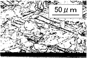
- FIG. It is an optical microscope photograph (800 times) which image
- FIG. It is the optical microscope photograph (800 times) which image
- Optical micrographs 200 times left, 400 times right, 400 times right taken of a plate thickness section parallel to the rolling direction after the bending property evaluation test of the alloy strips manufactured in Example 4 (top) and Comparative Example 34 (bottom). Times).
- Ni reacts with Si to form a compound having a Ni 2 Si composition and precipitates in the Cu matrix, suppressing the decrease in conductivity and greatly improving the strength.
- the amount of Ni added to the copper alloy of the present invention is 0.8 to 4.6% (mass%, the same shall apply hereinafter). If it is less than 0.8%, the precipitation amount is small and sufficient strength cannot be obtained. If it exceeds 50%, precipitates that do not contribute to strength improvement are produced during casting or hot working, and not only the strength corresponding to the amount added is obtained, but also hot workability and bending workability are adversely affected. It becomes coarse and protrudes from the end face of the lead frame, which deteriorates the adhesion of the noble metal plating.
- Si reacts with Ni without adversely affecting the electrical conductivity to form a compound having a Ni 2 Si composition. Accordingly, when the addition amount of Ni is determined, the optimum Si addition amount is determined.
- the amount of Si added to the copper alloy of the present invention is 0.3 to 1.6%. If it is less than 0.3%, sufficient strength cannot be obtained as in the case of Ni. Various problems similar to those of Ni occur.
- Mg Mg improves the stress relaxation properties, but is a component that degrades the heat-resistant peelability of the plating. If it exceeds 2.0 mass%, the heat-resistant peelability of the plating is lowered.
- Fe, Co, Cr, Mn Fe and Co react with Si to form silicide and precipitate, thereby contributing to strength improvement.
- Cr and Mn also have the effect of improving hot rollability. This is because these elements inevitably form a compound with sulfur present in the alloy because of their strong affinity with sulfur, reducing the segregation of sulfur to the ingot grain boundaries that cause hot rolling cracks. Because. The total amount of one or more of these elements is 2.0% or less, and if it exceeds 2.0%, the conductivity is lowered, which is not preferable.
- the non-uniform elongation tends to occur below the strain limit value corresponding to the original mechanical characteristics of the material, and the wrinkle of the bent portion tends to increase. Therefore, bending wrinkles can be reduced by reducing the starting points at which these non-uniform elongation occurs.
- Factors that serve as starting points for non-uniform elongation include roughness of the material surface and precipitates present on the surface layer. The surface roughness of the material can be reduced by conventional means such as surface polishing of the surface of the final rolling roll, but it alone cannot cope with the bending process required for the latest ultra-small terminals.
- Shear band in metal structure In general, copper alloys can be strengthened by adjusting the grain size (crystal refinement) of metal crystals, the amount of precipitates, grain size, and distribution (precipitation strengthening). It can also be strengthened by adjusting the degree of hot rolling (strengthening process). In rolling, a load applied by a rolling roll is applied from the vertical direction to a material in which tension is applied in the longitudinal direction, and the material is deformed (rolled). During this rolling, shear deformation locally concentrates, the crystal grain structure is deformed and broken, and a band-like structure called a shear band is formed regardless of the crystal orientation.
- the line of the shear band of the present invention is an angle of about 10 to 60 ° with the flat crystal grain structure aligned in parallel to the rolling direction, which is recognized when a sheet thickness section parallel to the rolling direction of the rolled material is observed.
- a line that intersects at. For example, in a portion surrounded by an ellipse in FIG. 2, it can be confirmed that a plurality of shear bands extending from the lower left to the upper right are arranged in parallel.
- the shear band is a structure in which deformation is locally concentrated, that is, a portion where dislocation density increases due to increased strain, and is less likely to be deformed than the surrounding structure. For this reason, in a material having a shear band, non-uniform elongation occurs starting from the shear band when bending is performed, and wrinkles and cracks occur when the non-uniform elongation reaches the surface. However, if the rolling process is not performed until the shear band is formed, the work cannot be strengthened and the required alloy strength cannot be achieved. Therefore, the product after the final cold rolling must have the shear band inherent. Yes.
- the present inventors paid attention to the distribution of the shear band, and found that the smaller the shear band near the surface of the material, the less likely the non-uniform elongation to reach the surface is, so that cracks and wrinkles are reduced. That is, when the strain embodied as a shear band is less in the surface layer than the central portion of the plate thickness, cracks and wrinkles are unlikely to occur during bending.
- the ratio Ss / Sc of the number Ss of shear band lines observed on the material surface layer after the final rolling and the number Sc of shear band lines at the center of the plate thickness (the portion other than the surface layer) is 1. If it is 0 or less, preferably 0.95 or less, the occurrence of bending wrinkles is reduced even during severe bending.
- the number of the shear band lines on the material surface layer after the final rolling is preferably 10/10000 ⁇ m 2 or less, more preferably 5/10000 ⁇ m 2 or less, the occurrence of bending wrinkles is reduced.
- the total degree of work in the final rolling is lowered and the work strengthening is not performed sufficiently, and there are few shear bands in the surface layer of the material or the center of the plate thickness, it is possible to obtain a high strength alloy strip of the present invention. Can not.
- the shear band is mechanically polished on a plate thickness section parallel to the rolling direction, immersed in an acidic aqueous solution such as dilute sulfuric acid or dilute nitric acid, and etched to reveal crystal grain boundaries and shear bands. It can be observed at a magnification of about 200 to 800 times using a microscope (see FIGS. 1 to 3).
- the line of the shear band is a line having a length of 5 ⁇ m or more that intersects the crystal grain boundary at one or more places with an inclination of about 10 to 60 ° with respect to the rolling direction.
- the normal size of the shear band is 1 ⁇ m or less in width and 5 to 30 ⁇ m in length.
- Shear bands are likely to occur in the portion where the strain accumulates. Strain tends to accumulate locally in the vicinity of the precipitate particles in a portion where the structure becomes discontinuous, that is, in a Corson alloy. Therefore, if the density of the precipitate particles is low, the localization of strain is suppressed, and a shear band is hardly generated.
- the “precipitate” of the present invention is a crystallized product generated during the solidification process during casting, oxides or sulfides generated by a reaction in the molten metal during melting, cooling process after ingot solidification, hot It is a general term for metal compounds such as precipitates that precipitate in the Cu matrix base material during rolling and after the solution treatment and cooling process and aging treatment. Accordingly, some of the precipitate particles are made of Ni and Si, and some of the particles are obtained by further adding an additive alloy element to the particles, and some of them do not contain either Ni or Si or both.
- the particle size and number of the precipitates can be observed at a magnification of about 200 to 2000 times using an FE-SEM (electrolytic emission scanning electron microscope) after the material is etched with an aqueous ferric chloride solution. Components were measured using particle analysis software and EDS (energy dispersive X-ray analysis), and particles composed of components different from the base material components were determined as precipitates. The particle size of each precipitate was measured and counted. Here, the diameter of the circle circumscribing the precipitate is defined as the particle size of the precipitate.
- the present invention is not limited by theory, in the surface layer from the surface of the material after aging treatment to 1/6 plate thickness depth, the number of precipitates having a particle diameter of 1 to 10 ⁇ m is 1.0 ⁇ 10 2 / if mm 2 or less, due to the low density of the precipitates as the starting point of shear bands occurrence, the occurrence of shear bands in the surface layer portion is reduced, wrinkles can also be reduced which occurs bend. On the other hand, when it exceeds 1.0 ⁇ 10 2 pieces / mm 2 , the generation of shear bands in the surface layer increases, and the wrinkles generated in the bent portion increase.
- the number of precipitates having a particle size of 1 to 10 ⁇ m in the surface layer is preferably 1 ⁇ 10 ⁇ 6 pieces / mm 2 or more, and if it is less than that, there is little precipitation as a whole material, and the effect of increasing the strength cannot be obtained.
- the conductivity tends to be low.
- the ratio Ns / Nc of the number Ns of precipitate particles having a particle diameter of 1 to 10 ⁇ m in the surface layer and the number Nc of precipitate particles having a particle diameter of 1 to 10 ⁇ m in the central part of the plate thickness is 1.0 or less, preferably 0.8. If it is 95 or less, the generation of wrinkles is reduced even after intense bending. This is because the number of precipitate particles in the surface layer is smaller than that in the central portion of the plate thickness, so that the surface layer is not distorted, the shear band is reduced, and cracks and wrinkles are less likely to occur during bending.
- the effect of improving the strength is observed due to the uniform presence of fine precipitates.
- the precipitate having a particle size of 1 ⁇ m or more causes a decrease in the distribution density of the precipitates and the interfacial area of the precipitates, thereby improving the strength. From the point of view, it was considered unfavorable.
- Precipitate particles having a particle size of less than 1 ⁇ m contribute to precipitation strengthening but do not contribute much to the localization of strain, and have little influence on the generation of shear bands, and therefore do not affect the wrinkles of the bent portion. Furthermore, the precipitate particles having a particle size of less than 0.5 ⁇ m are too small to determine whether the component is a precipitate. On the other hand, since a precipitate having a particle size exceeding 10 ⁇ m in the entire surface layer and the center of the plate thickness causes cracking, the number is preferably 1 piece / mm 2 or less, more preferably 0 piece / mm 2 .
- the heating temperature before hot rolling is 1000 ° C. or higher, a large amount of scale is generated, Since problems such as generation of cracks during rolling occur, the heating temperature before hot rolling is preferably 800 ° C. or higher and lower than 1000 ° C.
- Corson alloy is a solution treatment in which Ni-Si-based precipitates deposited by casting or hot rolling after the hot rolling process are dissolved in a Cu matrix, and heat treatment at a temperature lower than the solution treatment temperature.
- it is manufactured by a combination of aging treatment for precipitating Ni and Si dissolved in solution treatment and rolling for work hardening before and after the aging treatment.
- it is manufactured in the steps of solution treatment, rolling, aging treatment, rolling, and strain relief annealing. Rolling before and after aging treatment can be omitted in consideration of mechanical properties such as required tensile strength and 0.2% proof stress and bending workability.
- the solution treatment temperature when the solution treatment temperature is higher, the amount of Ni and Si dissolved in the Cu matrix increases, and during the aging treatment, Ni—Si-based intermetallic compounds are precipitated from the matrix to improve the strength.
- the solution treatment temperature for obtaining this effect is 700 ° C. or higher, preferably 800 to 950 ° C. If the copper alloy of the present invention is about 950 ° C., Ni and Si are sufficiently dissolved in the matrix. However, if the temperature exceeds 950 ° C., the surface of the material is heavily oxidized during solution heat treatment, and the oxide layer A treatment temperature of 950 ° C. or lower is preferable because the load of the pickling process for removing the water increases.
- the present invention is not limited by theory, by reducing the cooling rate, the difference in cooling rate between the surface layer and the central portion of the plate thickness increases, and the vicinity of the surface layer is rapidly cooled to reduce precipitates, and the central portion of the plate thickness. Then, it is considered that the precipitate is increased by slow cooling.
- the average cooling rate from the solution temperature to 400 ° C. is preferably 500 ° C./min or less, more preferably 500 to 300 ° C./min, and most preferably 500 to 400 ° C./min.
- the number of precipitates having a particle size of 1 ⁇ m or more is reduced because the surface layer is rapidly cooled, and precipitates having a particle size of 1 to 10 ⁇ m are generated because it is gradually cooled in the central portion. If it exceeds 500 ° C./min, it will be deposited almost uniformly inside the material, resulting in poor bendability and appearance after bending. If it is less than 300 ° C./min, the precipitate at the center of the plate thickness becomes coarse and the effect of precipitation strengthening due to aging cannot be sufficiently obtained.
- the average cooling rate from 400 ° C. to 70 ° C. is preferably 300 ° C./min or less, more preferably 300 to 100 ° C./min. If it exceeds 300 ° C./min, it will be deposited almost uniformly inside the material, resulting in poor appearance after bending. On the other hand, if it is less than 100 ° C./min, the precipitate in the central part of the plate thickness becomes coarse and the effect of precipitation strengthening due to aging cannot be sufficiently obtained. In addition, since it takes time, it is not preferable industrially. In the present invention, the average cooling temperature is used because it is actually difficult to make the cooling rate constant in cooling from the solution temperature.
- the average cooling rate of the present invention is the solution temperature and 400 ° C, or the difference between 400 ° C and 70 ° C divided by the time taken for cooling. Further, the theoretical solution temperature varies depending on the Ni and Si contents, and the actual solution treatment is +50 to 200 ° C. from the solid solution limit temperature of each Ni 2 Si concentration in the Cu—Ni 2 Si phase diagram. It carried out in the range of.
- the aging treatment is performed in order to grow fine precipitates in the solution-treated material and obtain desired strength and conductivity.
- the aging treatment temperature is preferably 300 to 700 ° C, more preferably 400 to 650 ° C. If it is less than 300 ° C, the aging treatment takes time and it is not economical. If it exceeds 650 ° C, the Ni-Si particles become coarse, and if it exceeds 700 ° C, Ni and Si are dissolved, improving strength and conductivity. It is because it does not.
- the aging treatment is performed in the range of 300 to 700 ° C., sufficient strength and conductivity can be obtained if the aging treatment time is 1 to 10 hours.
- the shear band is generated by localizing the strain introduced in the material.
- the rolling load per 1 mm in the width direction of the material is preferably 50 to 150 kg / mm, more preferably 70 to 150 kg / mm. If it is less than 50 kg / mm, it cannot be sufficiently reduced. On the other hand, if it exceeds 150 kg / mm, strain tends to concentrate on the surface of the material and the number of surface shear bands increases.
- the viscosity of the rolling oil should be low so that the work deformation occurs uniformly in the surface layer and the central part in the final cold rolling.
- the viscosity of the rolling oil is preferably 11 to 7 cST, more preferably 10 to 8 cST. If it is less than 7 cST, it is not sufficiently caught between the roll and the material and does not serve as rolling oil. On the other hand, if it exceeds 11 cST, the rolling oil is caught in the surface of the material during rolling, resulting in poor surface smoothness and distortion in the surface layer, increasing the number of surface shear bands.
- the total degree of cold rolling is 15 to 80%, and can be arbitrarily selected for required mechanical properties such as tensile strength and 0.2% proof stress and bending workability.
- the degree of processing per pass is over 5%, preferably 10% or more. If it is 5% or less, the number of passes increases, and the number of shear layers on the surface layer increases.
- heat treatment strain relief annealing
- the surface roughness can be adjusted, for example, by rolling or polishing.
- the surface roughness of the copper alloy can be adjusted by rolling using a rolling roll or the like whose surface roughness is adjusted.
- the surface average roughness Ra of the alloy strip of the present invention after the following bending evaluation is 2.0 ⁇ m or less, preferably 1.5 ⁇ m or less.
- the respective average cooling rates at solution treatment temperatures of ⁇ 400 ° C. and 400 ° C. to 70 ° C. are adjusted to a predetermined rate.
- the number of precipitates having a particle size of 1 to 10 ⁇ m in the surface layer and the center of the plate thickness was adjusted.
- each composition was subjected to aging treatment for 5 hours at a temperature (400 to 600 ° C.) at which the highest strength was obtained by precipitation strengthening, and then cooled to 0.25 mm.
- Rolled for a while In cold rolling, various rolling loads and rolling oil viscosities were selected, and the number of shear bands on the sample surface layer was adjusted.
- the rolling oil used was Idemitsu Kosan Co., Ltd. trade name Daphne Stainless Oil X-60 (viscosity 9.5 cST) or Idemitsu Kosan Co., Ltd. trade name Daphne Stainless Oil X-3K viscosity (12 cST).
- Mineral oil was added to a rolling oil having a viscosity of 12 cST or a rolling oil having a viscosity of 9.5 cST to adjust the viscosity of the rolling oil.
- Examples 30 and 31 were subjected to the above solution treatment as in Examples 1 to 29 and Comparative Examples 32 to 45, and then cold-rolled to 0.25 mm.
- Examples 1 to 29 and Comparative Examples 32 to 45 were cold-rolled after the aging treatment, and thereafter, strain relief annealing (550 ° C., 15 seconds) was performed.
- rolling may be performed before the aging treatment, in which case the strain relief annealing after aging can be omitted.
- the strain relief annealing after aging was omitted. Further, when cold rolling is performed before and after the aging treatment, strain relief annealing is performed after the final cold rolling.
- a total field of view of 2 mm 2 randomly selected from the surface to 1/6 depth of the plate thickness was observed using an 800 ⁇ optical microscope.
- the central part of the plate thickness other than the surface layer was observed.
- the shear band was evaluated as a line having a length of 5 ⁇ m or more that formed an angle of 10 to 60 ° with the rolling direction and straddled one or more grain boundaries.
- the number of particles having a particle size of 1 to 10 ⁇ m was counted using particle analysis software (EDS particle / phase analysis software manufactured by Phoenix).
- particle analysis software EDS particle / phase analysis software manufactured by Phoenix.
- precipitates having a particle size exceeding 10 ⁇ m were not present in the surface layer and the central portion of the plate thickness.
- (C) Average crystal grain size The crystal grain size was measured based on a cutting method (JIS 0501) defined by JIS. Specifically, the sample is filled with a resin so that the observation surface is perpendicular to the rolling direction, the observation surface is mirror-finished by mechanical polishing, and then 10 parts by volume of hydrochloric acid having a concentration of 36% with respect to 100 parts by volume of water. In the mixed solution, ferric chloride having a weight of 5% of the weight of the solution was dissolved. The sample was immersed in the solution thus prepared for 10 seconds to reveal the metal structure.
- JIS 0501 cutting method defined by JIS.
- the metallographic structure is magnified 1000 times with an optical microscope, photographed, and a 200 mm line segment is parallel to the plate width direction of the sample by a cutting method (JIS H0501) defined by JIS.
- JIS H0501 a cutting method defined by JIS.
- a total of 10 lines of 5 lines and 5 perpendicular lines were drawn at intervals of 25 mm, and the number of crystal grains n cut by the line segment was counted, and obtained from the formula [200 mm ⁇ 10 / (n ⁇ 1000)].
- the number of observed fields is one field arbitrarily selected at the center of the plate thickness for each sample.
- (D) Tensile test In accordance with JIS Z 2241, a tensile test was performed in parallel with the rolling direction using a JIS No. 13B tensile test piece to determine the tensile strength (tensile strength, MPa).
- “high strength” means that the tensile strength is usually 680 MPa or more, preferably 780 MPa or more, more preferably 800 MPa or more, in the above measurement method.
- (E) Conductivity Conductivity (% IACS) was measured by a four-terminal method in accordance with JIS H 0505. Preferably it is 44.0% IACS or more, More preferably, it is 45.0% IACS or more.
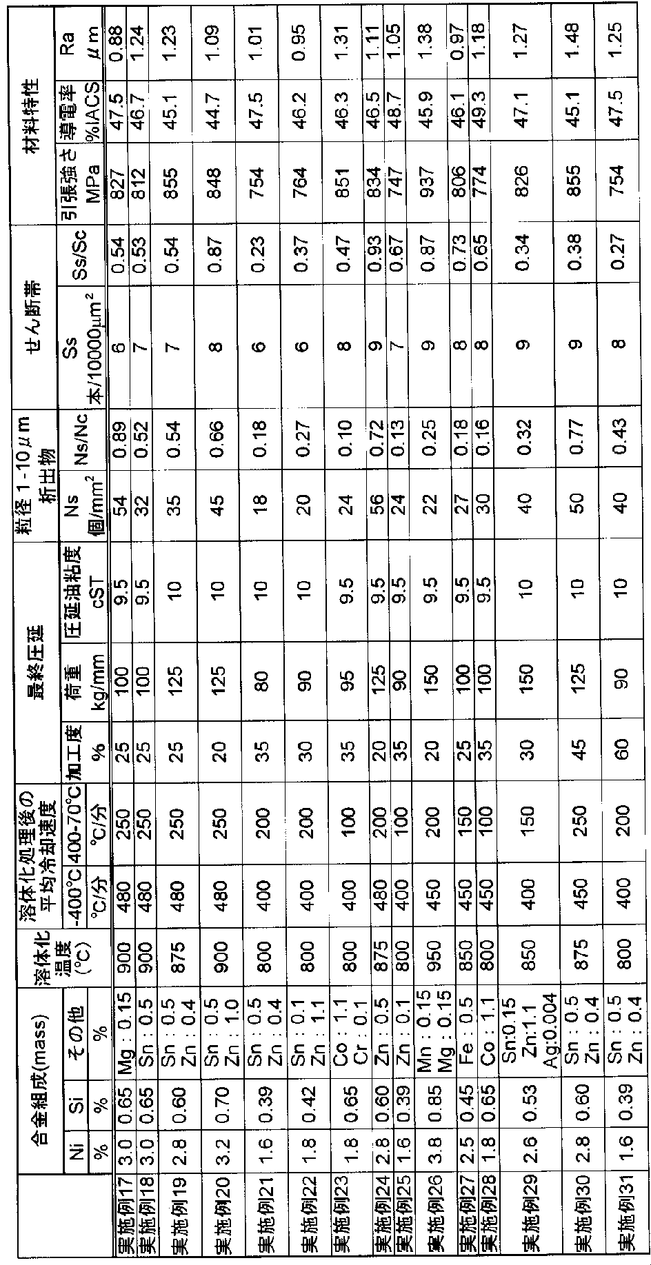
- Tables 1 to 3 show the manufacturing conditions and characteristics of the materials produced as described above.
- Examples 1 to 16 are alloy strips of the present invention to which other metal components are not added.
- Examples 17 to 31 are examples in which other optional metal components are added within the range.
- the surface layer / plate thickness central portion ratio Ss / Sc of the number of shear bands is less than 1.0
- the number Ss of the surface layer of shear bands is ten / 10000 2 below. Therefore, the appearance of the surface portion after bending was excellent.
- Examples 30 and 31 are examples in which rolling and aging are sequentially performed after solution treatment, and final strain relief annealing is not performed, but the number of shear bands Ss, Ss / Sc, etc. are adjusted within the present invention. It can be seen that the same characteristics as those of the present invention can be obtained.
- Comparative Example 35 on the contrary, the average cooling rate from the solution temperature to 400 ° C. was slowed to 100 ° C./min. However, the number of precipitates on the surface layer was relatively large and the number of shear bands on the surface layer was large. The bending skin was poor, and the tensile strength was low due to the effect of coarse precipitates. Comparative Examples 36 and 37 are examples in which the average cooling rate from 400 ° C. to 70 ° C. was changed.
- Comparative Example 36 as a result of increasing the average cooling rate, the ratio Ns / Nc of the number of precipitates having a particle size of 1 to 10 ⁇ m on the surface layer and the number of precipitates in the central part of the plate thickness was larger than 1, resulting in shearing of the surface layer. The number of strips was larger than that at the center, and the surface appearance of the bent part after bending was inferior. In Comparative Example 37, since the cooling rate was too slow, the number of precipitates of 1 to 10 ⁇ m on the surface layer was large. Further, the precipitate in the central part of the plate thickness was aggregated and coarsened.
- the ratio Ns / Nc between the number of precipitates having a particle size of 1 to 10 ⁇ m on the surface layer and the number of precipitates in the center of the plate thickness is greater than 1, the number of shear bands on the surface layer is increased, and the appearance of the bent portion was inferior. Also, the tensile strength was low due to the effect of coarse precipitates.
- Comparative Examples 38 and 39 have a constant average cooling rate from the solution temperature to 70 ° C, but Comparative Example 38 has a high average cooling rate from 400 ° C to 70 ° C. Since the average cooling rate to 400 ° C and the average cooling rate from 400 ° C to 70 ° C are both high, the amount of precipitates of 1 to 10 ⁇ m in the surface layer is larger than that in the central part of the plate thickness. And the appearance of the bent part was inferior. In Comparative Example 40, since the rolling load was too large, the number of surface shear bands was large, and the appearance of the bent portion was inferior.
- Comparative Example 41 since the rolling load was small and the rolling force was small, even when the number of rolling passes was 20 passes, it was not possible to roll to a predetermined plate thickness, and it was determined that it was not industrial, and the evaluation was interrupted.
- Comparative Example 42 the viscosity of the rolling oil was too high, so the number of surface shear bands was large, and the appearance of the bent portion was inferior.
- Comparative Example 43 the viscosity of the rolling oil was low, slip occurred between the material and the rolling roll, and the surface of the material was severely damaged.
- Comparative example 44 is an example in which the degree of processing per pass at the time of final rolling is 5%. Since the degree of processing per pass is reduced, the number of passes is as many as 10 and productivity is poor.
- Comparative Example 45 is an example in which the strain relief annealing condition after final rolling was performed under the same conditions as Comparative Example 44 was changed to 600 ° C. ⁇ 1 minute, but the number of precipitates on the surface layer slightly decreased to 42. However, the number of surface shear bands was still as many as 30, and the appearance of the bent portion was inferior.
- a high-strength copper alloy showing an excellent bent portion appearance that does not cause wrinkles or cracks in the bent portion appearance after bending is obtained, and a copper alloy for electronic materials such as terminals and connectors is obtained. It is suitable as.
Landscapes
- Chemical & Material Sciences (AREA)
- Engineering & Computer Science (AREA)
- Materials Engineering (AREA)
- Mechanical Engineering (AREA)
- Metallurgy (AREA)
- Organic Chemistry (AREA)
- Physics & Mathematics (AREA)
- Thermal Sciences (AREA)
- Crystallography & Structural Chemistry (AREA)
- Conductive Materials (AREA)
- Non-Insulated Conductors (AREA)
Abstract
Ni0.8~4.6質量%及びSi:0.3~1.6質量%、並びに任意成分Sn、Zn、Fe、Co、Cr、Mg及びMnのうち1種以上を総量2.0質量%以下含有し、表層のせん断帯の線の本数が、板厚中央部のせん断帯の線の本数に対して1.0以下である、高強度で曲げ加工後の外観に優れたCu-Ni-Si系合金条であり、好ましくは表層のせん断帯本数が10本/10000μm2以下、表層の1~10μmの析出物粒子個数が1.0×102個/mm2以下、表層の1~10μm析出物粒子数が中央部の数に対し1.0以下である。
Description
本発明はリードフレームやコネクター等の電子材料、車載コネクタ用端子などに利用される高強度銅合金に関する。詳細には、曲げ加工後の曲げ部外観にしわや割れを生じない優れた曲げ加工性及び曲げ部外観を示す高強度銅合金に関する。
近年、携帯電話、デジタルカメラ、ビデオカメラ等の電子機器や車載コネクタでの高密度実装化が進展し、その部品は著しく軽薄・短小化している。使用される材料も薄肉化の傾向が顕著で、材料にはより高強度なものが求められている。また、部品の形状も複雑化し、従来よりも厳しい曲げ加工が施されるケースが増えており、高強度化しても曲げ性は従来材と同等、もしくは箱曲げや180度密着曲げだけではなく、板厚を減厚させるつぶし加工後に曲げを行い割れが無いことなど、更に優れた曲げ加工性が要求されてきている。
これら電気機器用部材には強度と導電性及び曲げ性のバランスが優れているコルソン合金(Cu-Ni-Si系銅合金)が使用される。一般的には合金の強度を高めると曲げ性が悪化し、また、曲げ性が良いものは強度が低い。そこで、強度と曲げ性を両立させる改善が種々行われてきた。例えば特許文献1及び2では、特定元素を一定量含有するコルソン合金において、Ni及びSiからなる析出物並びに特定元素を含有する析出物それぞれの粒径及び個数を制御することにより、引張強度及び曲げ加工性、その他耐応力緩和特性に優れた銅合金を開示している。また、特許文献3では、コルソン合金表面を平滑化するとともに圧縮残留応力を付与して製品曲げによる引張応力に対抗させ、クラックの発生を抑制している。
コルソン合金の曲げ部外観、特に曲げ軸が圧延方向と直行する曲げ(GW)の外観はりん青銅のそれよりも劣り、肌荒れが大きい特徴がある。もし端子において割れが発生した場合、端子に求められる特性の導電性およびバネ性が失われ、製品の信頼性が損なわれるため、製品曲げ部の外観検査が通常行われている。しかし、例えば、最先端の超小型端子の曲げ部の外観の状況を裸眼で確認するのは難しく、曲げプレス後の状況を確認する検査工程では拡大鏡を使用して目視する、またはCCDカメラによる表面検査装置により確認するなど冶具や機械に頼らざるを得ない。この検査の際、実際には割れてはいないが、曲げ部外観の肌荒れが激しいため割れと区別が困難な場合は検査確認に時間がかかり検査効率が低下する。そこで、超小型電子機器材料に使用されるコルソン合金には、ただ曲げ部に割れが発生しなければ良いのではなく、曲げ部の肌荒れも小さいものが求められるようになってきている。
しかし、特許文献1、2の実施例中、最も曲げ性が良好なものでもMBR/t(割れが発生せずに曲げ可能な最小曲げ半径と板厚の比)は0.5で従来からあるコルソン合金の強度と曲げ性の関係から脱却しておらず、近年求められている厳しい曲げ加工には対応できない。更に、同実施例では最も曲げ性が良好なMBR/tが0.5以上であることから曲げ部のしわも大きいと考えられ、厳しい曲げ加工及びその外観検査が要求される超小型コネクタ端子用途には不向きである。
又、特許文献3は繰り返し曲げに対する疲労特性を向上させることを目的として製品表面粗さには着目しているが、曲げ加工後の曲げ部外観の改良を目的としていない。従って、曲げ加工前の表面粗さのみ評価され、曲げ加工後は評価されていない。
本発明は、コルソン系銅合金の優れた曲げ性、詳しくは割れのみならず、GW(good way)の曲げ加工後の、従来注目されていなかった曲げ部の肌荒れを改良することを目的とした。
又、特許文献3は繰り返し曲げに対する疲労特性を向上させることを目的として製品表面粗さには着目しているが、曲げ加工後の曲げ部外観の改良を目的としていない。従って、曲げ加工前の表面粗さのみ評価され、曲げ加工後は評価されていない。
本発明は、コルソン系銅合金の優れた曲げ性、詳しくは割れのみならず、GW(good way)の曲げ加工後の、従来注目されていなかった曲げ部の肌荒れを改良することを目的とした。
本発明者らは、GWの曲げ性及び曲げ部の肌荒れの改善を目的として研究した結果、異物や欠陥などの不均一伸びの起点となる部分を表面近くから排除し、板厚中央部(下記表層以外の部分)に比べて表層(材料表面から板厚の1/6深さまで)のせん断帯の形成を抑えることにより材料本来の引張強さ、0.2%耐力、ばね限界値などの機械的特性はそのままにGWの曲げ部の肌荒れを改善できることを発見して本発明を完成させた。
本発明は下記構成を有する。
(1) 質量百分率(%)に基づいて(以下、%と表記する)Ni:0.8~4.6%及びSi:0.3~1.6%、並びに任意成分Sn、Zn、Fe、Co、Cr、Mg及びMnのうち1種以上を総量で2.0%以下の範囲で含有し、残部がCu及び不可避的不純物から成る銅合金であって、材料表面から板厚の1/6深さまで(以下「表層」と表記する)のせん断帯の線の本数Ssと、材料表層以外の部分(以下「板厚中央部」と表記する。)のせん断帯の線の本数Scの比Ss/Scが1.0以下であることを特徴とする、高強度でかつ曲げ加工後の外観にも優れたCu-Ni-Si系合金条。
(2) 材料表層のせん断帯の線の本数が10本/10000μm2以下であることを特徴とする(1)に記載のCu-Ni-Si系合金条。
(3) 材料表層では、粒径1~10μmの析出物の個数が1.0×10²個/mm2以下であり、かつ表層における粒径1~10μmの析出物の個数Nsと、板厚中央部における粒径1~10μmの析出物の個数Ncの比Ns/Ncが1.0以下であることを特徴とする(1)又は(2)に記載のCu-Ni-Si系合金条。
本発明は下記構成を有する。
(1) 質量百分率(%)に基づいて(以下、%と表記する)Ni:0.8~4.6%及びSi:0.3~1.6%、並びに任意成分Sn、Zn、Fe、Co、Cr、Mg及びMnのうち1種以上を総量で2.0%以下の範囲で含有し、残部がCu及び不可避的不純物から成る銅合金であって、材料表面から板厚の1/6深さまで(以下「表層」と表記する)のせん断帯の線の本数Ssと、材料表層以外の部分(以下「板厚中央部」と表記する。)のせん断帯の線の本数Scの比Ss/Scが1.0以下であることを特徴とする、高強度でかつ曲げ加工後の外観にも優れたCu-Ni-Si系合金条。
(2) 材料表層のせん断帯の線の本数が10本/10000μm2以下であることを特徴とする(1)に記載のCu-Ni-Si系合金条。
(3) 材料表層では、粒径1~10μmの析出物の個数が1.0×10²個/mm2以下であり、かつ表層における粒径1~10μmの析出物の個数Nsと、板厚中央部における粒径1~10μmの析出物の個数Ncの比Ns/Ncが1.0以下であることを特徴とする(1)又は(2)に記載のCu-Ni-Si系合金条。
本発明は、端子、コネクター等電子材料用銅合金として好適な優れた曲げ加工性及びしわのない曲げ部外観を示す高強度銅合金を提供できる。
本発明の特定要素を以下に説明する。
(1)銅合金の組成
Ni:NiはSiと反応してNi2Si組成の化合物を生成しCuマトリックス中に析出して、導電性の低下を抑えて強度を大幅に向上させる。本発明の銅合金へのNi添加量は0.8~4.6%(質量%、以下同じ)であり、0.8%未満では析出量が少なく充分な強度が得られず、4.6%を超えると鋳造又は熱間加工時に強度向上に寄与しない析出物が生成し、添加量に見合う強度が得られないばかりか、熱間加工性や曲げ加工性に悪影響を及ぼし、又析出物が粗大化してリードフレーム端面から突出して貴金属めっきの密着性を悪化させる。
(1)銅合金の組成
Ni:NiはSiと反応してNi2Si組成の化合物を生成しCuマトリックス中に析出して、導電性の低下を抑えて強度を大幅に向上させる。本発明の銅合金へのNi添加量は0.8~4.6%(質量%、以下同じ)であり、0.8%未満では析出量が少なく充分な強度が得られず、4.6%を超えると鋳造又は熱間加工時に強度向上に寄与しない析出物が生成し、添加量に見合う強度が得られないばかりか、熱間加工性や曲げ加工性に悪影響を及ぼし、又析出物が粗大化してリードフレーム端面から突出して貴金属めっきの密着性を悪化させる。
Si:Siは導電性に悪影響を及ぼすことなくNiと反応してNi2Si組成の化合物を生成する。従ってNiの添加量が決まると最適なSi添加量が決まる。本発明の銅合金へのSi添加量は0.3~1.6%であり、0.3%未満では、Niの場合と同様に充分な強度が得られず、1.6%を超えるとNiの場合と同様の種々の問題が生じる。
Sn:Snを含有することにより強度が高くなる事が期待される。しかし、通常は、Snめっきが施されたコネクタ等の電子材料をスクラップとして回収し、製錬工程無しに低コストで再利用する場合には不可避的に再利用銅合金材料に含まれ、2.0質量%を超えると導電率が低下することから、上限を2.0質量%とした。
Zn:Znは銅合金に錫めっきを行った場合の錫めっき層の耐熱剥離性などの耐熱性を向上させるが、2.0質量%を超えると導電率が低下することから、上限を2.0質量%とした。
Mg:Mgは応力緩和特性を向上させるが、めっきの耐熱剥離性を劣化させる成分であり2.0質量%を超えるとめっきの耐熱剥離性が低下する。
Fe、Co、Cr、Mn:Fe及びCoはSiと反応して珪化物を形成して析出して、強度向上に寄与する。Cr及びMnは更に熱間圧延性を改善する効果も有する。この理由は、これらの元素が硫黄との親和性が強いため不可避的に合金中に存在する硫黄と化合物を形成し、熱間圧延割れの原因となるインゴット粒界への硫黄の偏析を軽減するためである。これら元素1種以上の添加量は、総量で2.0%以下であり、2.0%を超えると、導電性の低下を招くので好ましくない。
Zn:Znは銅合金に錫めっきを行った場合の錫めっき層の耐熱剥離性などの耐熱性を向上させるが、2.0質量%を超えると導電率が低下することから、上限を2.0質量%とした。
Mg:Mgは応力緩和特性を向上させるが、めっきの耐熱剥離性を劣化させる成分であり2.0質量%を超えるとめっきの耐熱剥離性が低下する。
Fe、Co、Cr、Mn:Fe及びCoはSiと反応して珪化物を形成して析出して、強度向上に寄与する。Cr及びMnは更に熱間圧延性を改善する効果も有する。この理由は、これらの元素が硫黄との親和性が強いため不可避的に合金中に存在する硫黄と化合物を形成し、熱間圧延割れの原因となるインゴット粒界への硫黄の偏析を軽減するためである。これら元素1種以上の添加量は、総量で2.0%以下であり、2.0%を超えると、導電性の低下を招くので好ましくない。
(2)曲げしわの原因
一般に、材料を曲げ加工する場合、曲げ部最外周に最も歪が付与される。曲げ加工において特定の歪値までは材料表面が均一に伸びるが、特定の歪値を境界に局部的に伸びが小さくなり、曲げしわが発生する。曲げ加工が進むとこのしわを起点に割れが入る。局部的に伸びが小さくなる(以降、不均一伸び)現象が生じる歪限界値は材料の機械的特性に依存するところも大きいが、材料内に異物や欠陥などの不均一伸びの起点となる物が存在すると、材料本来の機械的特性に応じた歪限界値以下で不均一伸びが生じやすく、曲げ部のしわが大きくなる傾向がある。従って、これら不均一伸びが生じる起点を少なくすることにより曲げしわを小さくできる。
なお、材料内部に不均一伸びが生じる起点が存在すると、材料表面に存在する起点ほどではないが、これが原因で材料表面に影響を及ぼすため、材料内部についても不均一伸びが生じる起点を少なくすることが望ましい。
不均一伸びの起点となる因子としては、材料表面の粗さ、表層に存在する析出物が挙げられる。材料表面の粗さは、最終圧延ロール表面の表面研磨等の従来手段で小さくすることは可能であるが、それだけでは最新の超小型端子に要求される曲げ加工に対応できない。
一般に、材料を曲げ加工する場合、曲げ部最外周に最も歪が付与される。曲げ加工において特定の歪値までは材料表面が均一に伸びるが、特定の歪値を境界に局部的に伸びが小さくなり、曲げしわが発生する。曲げ加工が進むとこのしわを起点に割れが入る。局部的に伸びが小さくなる(以降、不均一伸び)現象が生じる歪限界値は材料の機械的特性に依存するところも大きいが、材料内に異物や欠陥などの不均一伸びの起点となる物が存在すると、材料本来の機械的特性に応じた歪限界値以下で不均一伸びが生じやすく、曲げ部のしわが大きくなる傾向がある。従って、これら不均一伸びが生じる起点を少なくすることにより曲げしわを小さくできる。
なお、材料内部に不均一伸びが生じる起点が存在すると、材料表面に存在する起点ほどではないが、これが原因で材料表面に影響を及ぼすため、材料内部についても不均一伸びが生じる起点を少なくすることが望ましい。
不均一伸びの起点となる因子としては、材料表面の粗さ、表層に存在する析出物が挙げられる。材料表面の粗さは、最終圧延ロール表面の表面研磨等の従来手段で小さくすることは可能であるが、それだけでは最新の超小型端子に要求される曲げ加工に対応できない。
(3)金属組織内のせん断帯
一般的に銅合金は、金属結晶の粒径(結晶微細化)や析出物の量、粒径、分布(析出強化)等の調整により強化できるが、最終冷間圧延の加工度調整によっても強化できる(加工強化)。圧延では、長手方向に張力が負荷された材料に対し、鉛直方向から圧延ロールによる荷重が加えられ、材料が変形(圧延)されていく。この圧延の際には、せん断的な変形が局所的に集中し、結晶粒組織が変形破壊されてせん断帯と呼ばれる帯状の組織が結晶方位とは無関係に形成される。
本発明のせん断帯の線とは、圧延加工された材料の圧延方向に平行な板厚断面を観察した場合に認められる、圧延方向に平行に並ぶ扁平結晶粒組織と約10~60°の角度で交差して存在する線をいう。例えば、図2の楕円で囲まれた部分では左下から右上に続く複数のせん断帯が平行に並んでいるのを確認できる。
一般的に銅合金は、金属結晶の粒径(結晶微細化)や析出物の量、粒径、分布(析出強化)等の調整により強化できるが、最終冷間圧延の加工度調整によっても強化できる(加工強化)。圧延では、長手方向に張力が負荷された材料に対し、鉛直方向から圧延ロールによる荷重が加えられ、材料が変形(圧延)されていく。この圧延の際には、せん断的な変形が局所的に集中し、結晶粒組織が変形破壊されてせん断帯と呼ばれる帯状の組織が結晶方位とは無関係に形成される。
本発明のせん断帯の線とは、圧延加工された材料の圧延方向に平行な板厚断面を観察した場合に認められる、圧延方向に平行に並ぶ扁平結晶粒組織と約10~60°の角度で交差して存在する線をいう。例えば、図2の楕円で囲まれた部分では左下から右上に続く複数のせん断帯が平行に並んでいるのを確認できる。
せん断帯は変形が局部的に集中した組織、すなわち歪が多くたまって転位密度が増加している部分であり、周りの組織に比べ変形しにくい。このため、せん断帯が存在する材料では、曲げ加工した際にせん断帯を起点に不均一伸びが生じ、不均一伸びが表面まで達する場合にはしわや割れが発生する。しかし、せん断帯が形成されるまで圧延加工をしないと加工強化はできず、要求される合金強度を達成することができないため、最終冷間圧延後の製品は必然的にせん断帯を内在させている。
本発明者らはせん断帯の分布に着目し、材料表面近くのせん断帯が少ないほど表面に達する不均一伸びが生じにくいため、割れやしわが少なくなることを発見した。即ち、せん断帯として具現化される歪が板厚中央部より表層で少ない場合には、曲げ加工の際に割れやしわが発生しにくい。具体的には、最終圧延後の材料表層に観察されるせん断帯の線の本数Ssと、板厚中央部(表層以外の部分)のせん断帯の線の本数Scの比Ss/Scが1.0以下、好ましくは0.95以下であれば、激しい曲げ加工の際にも曲げしわの発生が少なくなる。
更に、最終圧延後の材料表層のせん断帯の線の本数が好ましくは10本/10000μm2以下、更に好ましくは5本/10000μm2以下であれば、曲げしわの発生がより少なくなる。
なお、最終圧延での総加工度を低くして加工強化を充分に行わず、材料の表層でも板厚中央部でもせん断帯が少なかった場合は、高強度な本発明の合金条を得ることはできない。
本発明者らはせん断帯の分布に着目し、材料表面近くのせん断帯が少ないほど表面に達する不均一伸びが生じにくいため、割れやしわが少なくなることを発見した。即ち、せん断帯として具現化される歪が板厚中央部より表層で少ない場合には、曲げ加工の際に割れやしわが発生しにくい。具体的には、最終圧延後の材料表層に観察されるせん断帯の線の本数Ssと、板厚中央部(表層以外の部分)のせん断帯の線の本数Scの比Ss/Scが1.0以下、好ましくは0.95以下であれば、激しい曲げ加工の際にも曲げしわの発生が少なくなる。
更に、最終圧延後の材料表層のせん断帯の線の本数が好ましくは10本/10000μm2以下、更に好ましくは5本/10000μm2以下であれば、曲げしわの発生がより少なくなる。
なお、最終圧延での総加工度を低くして加工強化を充分に行わず、材料の表層でも板厚中央部でもせん断帯が少なかった場合は、高強度な本発明の合金条を得ることはできない。
ここで、せん断帯は、圧延方向に平行な板厚断面を機械研磨後、希硫酸や希硝酸等の酸性水溶液に浸漬させてエッチングし、結晶粒界とせん断帯を現出させた後、光学顕微鏡を用いて200~800倍程度の倍率で観察できる(図1~3参照)。せん断帯の線は、圧延方向に対して約10~60°の傾きで、結晶粒界と1ヶ所以上で交差している長さ5μm以上の線である。せん断帯の通常の大きさは、幅1μm以下、長さ5~30μmである。
なお、図1~3で示される写真では左右両方向に向けてリバース圧延を行ったので、せん断帯もそれぞれの方向に対して形成され、せん断帯の線の角度は左右両方向に向かっている。
なお、図1~3で示される写真では左右両方向に向けてリバース圧延を行ったので、せん断帯もそれぞれの方向に対して形成され、せん断帯の線の角度は左右両方向に向かっている。
(4)析出物の粒径及び数
せん断帯は歪がたまる部分に発生しやすい。そして、歪は組織が不連続となる部分、すなわちコルソン系合金では析出物粒子の周辺に局所的にたまりやすい。よって、析出物粒子の密度が低ければ歪の局所化も抑えられ、せん断帯も発生しにくくなる。ここで、本発明の「析出物」は、鋳造時の凝固過程に生じる晶出物、溶解時の溶湯内での反応により生じる酸化物や硫化物等、鋳塊凝固後の冷却過程、熱間圧延後、溶体化処理後の冷却過程及び時効処理時にCuマトリックス母材中に析出する析出物等の金属化合物を包括して総称する。従って、析出物粒子は、Ni及びSiからなる粒子もあれば、この粒子に更に添加合金元素が加わったもの、Ni及びSiのいずれか一方を含まない、もしくは両方を含まないものもある。
析出物の粒径及び数は、材料を塩化第二鉄水溶液でエッチング後に、FE-SEM(電解放射型走査電子顕微鏡)を用いて200~2000倍程度の倍率で観察できる。粒子解析ソフト及びEDS(エネルギー分散型X線分析)を用いて成分を測定し、母材成分とは異なる成分で構成される粒子を析出物として判定した。析出物のそれぞれの粒径を測定して個数を数えた。ここで、析出物に外接する円の直径を析出物の粒径とする。
せん断帯は歪がたまる部分に発生しやすい。そして、歪は組織が不連続となる部分、すなわちコルソン系合金では析出物粒子の周辺に局所的にたまりやすい。よって、析出物粒子の密度が低ければ歪の局所化も抑えられ、せん断帯も発生しにくくなる。ここで、本発明の「析出物」は、鋳造時の凝固過程に生じる晶出物、溶解時の溶湯内での反応により生じる酸化物や硫化物等、鋳塊凝固後の冷却過程、熱間圧延後、溶体化処理後の冷却過程及び時効処理時にCuマトリックス母材中に析出する析出物等の金属化合物を包括して総称する。従って、析出物粒子は、Ni及びSiからなる粒子もあれば、この粒子に更に添加合金元素が加わったもの、Ni及びSiのいずれか一方を含まない、もしくは両方を含まないものもある。
析出物の粒径及び数は、材料を塩化第二鉄水溶液でエッチング後に、FE-SEM(電解放射型走査電子顕微鏡)を用いて200~2000倍程度の倍率で観察できる。粒子解析ソフト及びEDS(エネルギー分散型X線分析)を用いて成分を測定し、母材成分とは異なる成分で構成される粒子を析出物として判定した。析出物のそれぞれの粒径を測定して個数を数えた。ここで、析出物に外接する円の直径を析出物の粒径とする。
理論によって本発明を制限するものではないが、時効処理後の材料の表面から1/6板厚深さまでの表層において、粒径1~10μmの析出物の個数が1.0×102個/mm2以下であれば、せん断帯発生の起点となる析出物の密度が低いため、表層部分でのせん断帯の発生が少なくなり、曲げ部に発生するしわも小さくできる。一方、1.0×102個/mm2を超えると表層でのせん断帯の発生が多くなり、曲げ部に発生するしわが大きくなる。表層における粒径1~10μmの析出物の個数は好ましくは1×10-6個/mm2以上であり、それ未満であると材料全体として析出が少ない状態であり、強度上昇効果が得られず導電性も低い傾向がある。
また、表層における粒径1~10μmの析出物粒子の個数Nsと、板厚中央部の粒径1~10μmの析出物粒子の個数Ncの比Ns/Ncが1.0以下、好ましくは0.95以下であれば、激しい曲げ加工後にもしわの発生が少なくなる。これは、板厚中央部よりも表層で析出物粒子の個数が少ないため表層に歪がたまらず、せん断帯が少なくなり、曲げ加工の際に割れやしわが発生しにくいからである。
また、表層における粒径1~10μmの析出物粒子の個数Nsと、板厚中央部の粒径1~10μmの析出物粒子の個数Ncの比Ns/Ncが1.0以下、好ましくは0.95以下であれば、激しい曲げ加工後にもしわの発生が少なくなる。これは、板厚中央部よりも表層で析出物粒子の個数が少ないため表層に歪がたまらず、せん断帯が少なくなり、曲げ加工の際に割れやしわが発生しにくいからである。
なお、コルソン合金では微細な析出物が均一に存在することにより強度向上効果が見られるが、粒径1μm以上の析出物は、析出物の分布密度及び粒界面積の低下を引き起こすため強度向上の観点から余り好ましくないとされていた。しかし、本発明では、圧延加工による歪を局在化させてせん断帯が形成される原因となりやすい粒径1~10μmの析出物に着目し、その分布を調整して目的の特性を達成している。
粒径1μm未満の析出物粒子は、析出強化に寄与するが歪の局在化には余り寄与せず、せん断帯の発生にほとんど影響しないため曲げ部のしわにも影響しない。更に、粒径0.5μm未満の析出物粒子は、析出物であるか否かの成分判断ができないほど小さすぎる。一方、表層及び板厚中央部を含む全体において粒径10μmを超える析出物は割れの原因になるため、その個数は好ましくは1個/mm2以下、更に好ましくは0個/mm2である。
粒径1μm未満の析出物粒子は、析出強化に寄与するが歪の局在化には余り寄与せず、せん断帯の発生にほとんど影響しないため曲げ部のしわにも影響しない。更に、粒径0.5μm未満の析出物粒子は、析出物であるか否かの成分判断ができないほど小さすぎる。一方、表層及び板厚中央部を含む全体において粒径10μmを超える析出物は割れの原因になるため、その個数は好ましくは1個/mm2以下、更に好ましくは0個/mm2である。
(5)本発明の合金条の製造方法
次に、本発明の合金を得るための製造方法について説明する。
通常、コルソン合金の鋳塊の製造は半連続鋳造法で行なわれる。鋳造条件の温度、時間及び冷却速度を制御して、鋳造時の凝固過程において粗大なNi-Si系析出物を生成させないことが好ましい。ある大きさ以下のNi-Si系析出物は、鋳造後に行われる熱間圧延の加熱を強化することによりCuマトリックス中に固溶できるが、全ての粗大な析出物をマトリックス中に固溶させるために加熱温度を上昇させると加熱炉の炉体耐火物寿命が短くなり、加熱時間を長時間化させるとリードタイムが長くなり生産性が極端に悪化する等の問題が生じる。
次に、本発明の合金を得るための製造方法について説明する。
通常、コルソン合金の鋳塊の製造は半連続鋳造法で行なわれる。鋳造条件の温度、時間及び冷却速度を制御して、鋳造時の凝固過程において粗大なNi-Si系析出物を生成させないことが好ましい。ある大きさ以下のNi-Si系析出物は、鋳造後に行われる熱間圧延の加熱を強化することによりCuマトリックス中に固溶できるが、全ての粗大な析出物をマトリックス中に固溶させるために加熱温度を上昇させると加熱炉の炉体耐火物寿命が短くなり、加熱時間を長時間化させるとリードタイムが長くなり生産性が極端に悪化する等の問題が生じる。
800℃以上の温度で1時間以上加熱後に、終了温度を650℃以上とする熱間圧延を行なうと、鋳造で析出・晶出したある大きさ以下の析出物はCuマトリックス中に固溶される。その場合、高温で加熱すると鋳造時に析出・晶出した析出物をCuマトリックス中に固溶させることができるが、熱間圧延前の加熱温度が1000℃以上では、大量のスケールの発生、熱間圧延時の割れの発生といった問題が生じるので、熱間圧延前の加熱温度は800℃以上1000℃未満が好ましい。
コルソン合金は、上記熱間圧延加工後、加熱して鋳造や熱間圧延で析出したNi-Si系析出物をCuマトリックス中に固溶させる溶体化処理と、溶体化処理温度より低い温度で熱処理して溶体化処理で固溶したNiとSiを析出させる時効処理、時効処理の前後で加工硬化させる圧延を組み合わせた工程で製造されることが多い。一般的には溶体化処理、圧延、時効処理、圧延、歪取り焼鈍の工程で製造される。時効処理前後の圧延は要求される引張強さや0.2%耐力といった機械的特性および曲げ加工性を考慮し、時効前後のどちらか一方の圧延を省略することは可能である。
この場合、溶体化処理温度が高い方がNi、SiのCuマトリックス中への固溶量が増加し、時効処理時にマトリックス中からNi-Si系の金属間化合物が析出して強度を向上させる。この効果を得るための溶体化処理温度は、700℃以上、好ましくは800~950℃である。なお、本発明の銅合金は950℃程度であれば、Ni、Siがマトリックス中に充分固溶されるが、950℃を超える温度では、溶体化加熱処理時に材料表面の酸化が激しく、酸化層を除去するための酸洗工程の負荷が大きくなるため950℃以下の処理温度が好ましい。
この場合、溶体化処理温度が高い方がNi、SiのCuマトリックス中への固溶量が増加し、時効処理時にマトリックス中からNi-Si系の金属間化合物が析出して強度を向上させる。この効果を得るための溶体化処理温度は、700℃以上、好ましくは800~950℃である。なお、本発明の銅合金は950℃程度であれば、Ni、Siがマトリックス中に充分固溶されるが、950℃を超える温度では、溶体化加熱処理時に材料表面の酸化が激しく、酸化層を除去するための酸洗工程の負荷が大きくなるため950℃以下の処理温度が好ましい。
通常、溶体化処理工程ではNi及びSiの固溶状態を可能な限り維持するために急冷される。本発明では、実際にはいくら急冷しても溶体化処理の冷却過程で、ある程度の量のNi-Si金属間化合物が材料内部にほぼ均一に析出してしまうことに着目し、あえて溶体化処理工程での冷却速度を遅くすることにより、溶体化の冷却過程で表層と板厚中央部に温度勾配をつけ、粒径1~10μmの析出物数が表層から板厚中央部に向けて段階的に増加するように変化させて、最終冷間圧延後の表層せん断帯本数を少なくし、曲げ加工後でも優れた表面外観を示す合金条を得た。理論によって本発明を制限するものではないが、冷却速度を遅くすることにより表層と板厚中央部とで冷却速度の差が大きくなり、表層付近は急冷されて析出物が少なく、板厚中央部では徐冷されて析出物は多くなると考えられる。
溶体化温度から400℃までの平均冷却速度は、好ましくは500℃/分以下、さらに好ましくは500~300℃/分、最も好ましくは500~400℃/分である。上記範囲であると表層では急冷されるため粒径1μm以上の析出物数が低下し、中央部では徐冷されるため粒径1~10μmの析出物が発生する。500℃/分を超えると材料内部にほぼ均一に析出してしまうため、曲げ性及び曲げ加工後の外観に劣る。300℃/分未満であると板厚中央部の析出物が粗大化して時効での析出強化の効果が充分に得られない。
400℃から70℃までの平均冷却速度は、好ましくは300℃/分以下、さらに好ましくは300~100℃/分である。300℃/分を超えると材料内部にほぼ均一に析出してしまうため、曲げ加工後の外観に劣る。一方100℃/分未満であると板厚中央部の析出物が粗大化して時効での析出強化の効果が充分に得られない。その上、時間もかかるため工業的にも好ましくない。
本発明では溶体化温度からの冷却において冷却速度を一定にすることは実際には難しいので平均冷却温度を用いている。本発明の平均冷却速度は、溶体化温度と400℃、又は400℃と70℃との差を、冷却にかかった時間で割ったものである。
また、理論的な溶体化温度はNiおよびSi含有量に応じて変化し、実際の溶体化処理はCu-Ni2Siの状態図の各Ni2Si濃度の固溶限温度から+50~200℃の範囲で実施した。
400℃から70℃までの平均冷却速度は、好ましくは300℃/分以下、さらに好ましくは300~100℃/分である。300℃/分を超えると材料内部にほぼ均一に析出してしまうため、曲げ加工後の外観に劣る。一方100℃/分未満であると板厚中央部の析出物が粗大化して時効での析出強化の効果が充分に得られない。その上、時間もかかるため工業的にも好ましくない。
本発明では溶体化温度からの冷却において冷却速度を一定にすることは実際には難しいので平均冷却温度を用いている。本発明の平均冷却速度は、溶体化温度と400℃、又は400℃と70℃との差を、冷却にかかった時間で割ったものである。
また、理論的な溶体化温度はNiおよびSi含有量に応じて変化し、実際の溶体化処理はCu-Ni2Siの状態図の各Ni2Si濃度の固溶限温度から+50~200℃の範囲で実施した。
時効処理は溶体化処理後の材料中に微細析出物を成長させ、所望の強度及び導電性を得るために行われる。時効処理温度は好ましくは300~700℃、更に好ましくは400~650℃にする。300℃未満では時効処理に時間がかかり経済的でなく、650℃を超えるとNi-Si粒子は粗大化し、更に700℃を超えるとNi及びSiが固溶してしまい、強度及び導電性が向上しないためである。300~700℃の範囲で時効処理する際、時効処理時間は、1~10時間であれば充分な強度、導電性が得られる。
せん断帯は材料内に導入された歪が局所化することにより発生する。上記記載の通り粒径1~10μmの析出物の個数を表層部で少なく、板厚中央部で多く調整した材料へ、表層及び板厚中央部に対して均一に変形(圧延)を加えると、せん断帯が表層で少なく板厚中央部では加工強化に充分な程度に多く発生する。
最終冷間圧延において、材料の幅方向の長さ1mm当たりの圧延荷重は好ましくは50~150kg/mm、更に好ましくは70~150kg/mmである。50kg/mm未満であると充分圧下することができない。一方、150kg/mmを超えると材料表面に歪が集中しやすく表層のせん断帯が多くなる。
最終冷間圧延において、材料の幅方向の長さ1mm当たりの圧延荷重は好ましくは50~150kg/mm、更に好ましくは70~150kg/mmである。50kg/mm未満であると充分圧下することができない。一方、150kg/mmを超えると材料表面に歪が集中しやすく表層のせん断帯が多くなる。
また、最終冷間圧延で表層と中央部とで均一に加工変形が生じるように、圧延油の粘度は低い方がよい。圧延油の粘度は好ましくは11~7cST、更に好ましくは10~8cSTである。7cST未満であると十分ロールと材料の間に噛み込まず圧延油の役目を果たさない。一方、11cSTを超えると圧延の際に圧延油が材料表面に噛み込まれて表面平滑性に劣ると共に表層に歪がたまり、表層のせん断帯の本数が多くなる。
なお、冷間圧延の総加工度は15~80%で、要求される引張強さ、0.2%耐力といった機械的特性および曲げ加工性に対して任意に選択できる。1パスあたりの加工度は、5%を超え、好ましくは10%以上である。5%以下であるとパス回数が多くなり、表層のせん断帯の本数が多くなる。
本発明の銅合金において、最終冷間圧延後に熱処理(歪取り焼鈍)を行うことも可能である。
本発明の銅合金において、最終冷間圧延後に熱処理(歪取り焼鈍)を行うことも可能である。
本発明の銅合金は、曲げ加工後の表面外観の変化を評価するので材料表面外観が重要である。表面粗さの調整は、例えば、圧延、研磨などにより行うことが出来る。実際の操業においては表面粗度を調整した圧延ロール等を用いて圧延することにより、銅合金の表面粗度を調整することが出来る。また、圧延後の工程で材料表面に対して例えば、目の粗さが違うバフ研磨を実施することにより表面粗度を調整することも可能である。
本発明の合金条の下記曲げ加工評価後の表面平均粗さRaは、2.0μm以下、好ましくは1.5μm以下である。
本発明の合金条の下記曲げ加工評価後の表面平均粗さRaは、2.0μm以下、好ましくは1.5μm以下である。
以下に本発明に係るCu-Ni-Si系合金の製造例および特性試験の結果を示すが、これらは本発明およびその利点をより良く理解するために提供するのであり、本発明が限定されることを意図するものではないことに留意すべきである。
(製造方法)
高周波溶解炉にて各種成分組成の銅合金を溶製し、厚さ20mm、幅50mm、長さ150mmのインゴットを鋳造した。次に、Ni及びSiをマトリックス中に十分固溶させるためにこのインゴットを加熱温度800℃以上900℃未満の温度で2時間以上加熱した後、厚さ8mmまで終了温度が650℃以上となるように熱間圧延を行った。次いで、表面のスケール除去のため面削を施した後、所定の板厚まで圧延した。
次いで板厚に応じて850~950℃の温度で10分間の溶体化処理を行った後、溶体化温度~400℃および400℃~70℃におけるそれぞれの平均冷却速度を所定の速度に調節しながら冷却し、表層および板厚中央部の粒径1~10μmの析出物個数を調整した。
その後、実施例1~29、比較例32~45については各組成で析出強化により最高の強度が得られる温度(400~600℃)で5時間の時効処理を行い、次に0.25mmまで冷間圧延した。冷間圧延で、圧延荷重および圧延油の粘度を種々選択し、試料表層のせん断帯の本数を調整した。使用した圧延油は、出光興産社製 商品名ダフニーステンレスオイルX-60(粘度9.5cST)又は出光興産社製 商品名ダフニーステンレスオイルX-3K粘度(12cST)であった。粘度12cSTの圧延油又は粘度9.5cSTの圧延油へ鉱油を添加して圧延油の粘度を調整とした。
また、実施例30及び31については実施例1~29、比較例32~45と同様上述の溶体化処理を行った後、0.25mmまで冷間圧延した。冷間圧延で、圧延荷重および圧延油の粘度を種々選択し、試料表層のせん断帯の本数を調整した。使用した圧延油は上記と同様である。その後、各組成で析出強化により最高の強度が得られる温度(400~600℃)で5時間の時効処理を行った。
実施例1~31、比較例32~43での最終圧延のパス回数は、例えば総加工度15~30%の場合は1パス、総加工度30~50%の場合は2パス、これ以上は3パスというように加工度に応じて変更した。従って、1パスあたりの加工率は最小でも10%以上であった。
高周波溶解炉にて各種成分組成の銅合金を溶製し、厚さ20mm、幅50mm、長さ150mmのインゴットを鋳造した。次に、Ni及びSiをマトリックス中に十分固溶させるためにこのインゴットを加熱温度800℃以上900℃未満の温度で2時間以上加熱した後、厚さ8mmまで終了温度が650℃以上となるように熱間圧延を行った。次いで、表面のスケール除去のため面削を施した後、所定の板厚まで圧延した。
次いで板厚に応じて850~950℃の温度で10分間の溶体化処理を行った後、溶体化温度~400℃および400℃~70℃におけるそれぞれの平均冷却速度を所定の速度に調節しながら冷却し、表層および板厚中央部の粒径1~10μmの析出物個数を調整した。
その後、実施例1~29、比較例32~45については各組成で析出強化により最高の強度が得られる温度(400~600℃)で5時間の時効処理を行い、次に0.25mmまで冷間圧延した。冷間圧延で、圧延荷重および圧延油の粘度を種々選択し、試料表層のせん断帯の本数を調整した。使用した圧延油は、出光興産社製 商品名ダフニーステンレスオイルX-60(粘度9.5cST)又は出光興産社製 商品名ダフニーステンレスオイルX-3K粘度(12cST)であった。粘度12cSTの圧延油又は粘度9.5cSTの圧延油へ鉱油を添加して圧延油の粘度を調整とした。
また、実施例30及び31については実施例1~29、比較例32~45と同様上述の溶体化処理を行った後、0.25mmまで冷間圧延した。冷間圧延で、圧延荷重および圧延油の粘度を種々選択し、試料表層のせん断帯の本数を調整した。使用した圧延油は上記と同様である。その後、各組成で析出強化により最高の強度が得られる温度(400~600℃)で5時間の時効処理を行った。
実施例1~31、比較例32~43での最終圧延のパス回数は、例えば総加工度15~30%の場合は1パス、総加工度30~50%の場合は2パス、これ以上は3パスというように加工度に応じて変更した。従って、1パスあたりの加工率は最小でも10%以上であった。
本実施例の内、実施例1~29、比較例32~45については、時効処理後に冷間圧延したため、その後、歪取り焼鈍(550℃、15秒)を実施した。本発明では、時効処理の前に圧延しても良く、その場合は時効後の歪取り焼鈍は省略可能である。実施例30及び31では時効後の歪取り焼鈍を省略した。また、時効処理前後に冷間圧延する場合は、最終の冷間圧延後に歪取り焼鈍を行う。
(評価方法)
実施例1~29、比較例32~45については、歪取り焼鈍後の試料について、せん断帯の本数、析出物粒子の個数、結晶平均粒径、強度、導電性、曲げ加工性評価、引張試験、導電率試験を行った。
実施例30及び31については、時効処理後の試料について、同様の試験を行った。
(a)せん断帯の本数
せん断帯の観察は圧延平行の板厚断面に対して、3μmのダイヤモンドペーストを使用して機械研磨後、塩化第2鉄5g+塩酸30ml+水100mlの溶液に5~15秒程度浸漬させ、結晶粒界とせん断帯を現出させた後、表面から板厚の1/6深さまでの間でランダムに選んだ合計視野2mm2を800倍の光学顕微鏡を用いて観察した。同様に表層以外の板厚中央部(板厚の1/6深さから5/6深さまでの間)を観察した。せん断帯は、圧延方向と10~60°の角度を成し結晶粒界を1つ以上またいでいる長さ5μm以上の線として評価した。
実施例1~29、比較例32~45については、歪取り焼鈍後の試料について、せん断帯の本数、析出物粒子の個数、結晶平均粒径、強度、導電性、曲げ加工性評価、引張試験、導電率試験を行った。
実施例30及び31については、時効処理後の試料について、同様の試験を行った。
(a)せん断帯の本数
せん断帯の観察は圧延平行の板厚断面に対して、3μmのダイヤモンドペーストを使用して機械研磨後、塩化第2鉄5g+塩酸30ml+水100mlの溶液に5~15秒程度浸漬させ、結晶粒界とせん断帯を現出させた後、表面から板厚の1/6深さまでの間でランダムに選んだ合計視野2mm2を800倍の光学顕微鏡を用いて観察した。同様に表層以外の板厚中央部(板厚の1/6深さから5/6深さまでの間)を観察した。せん断帯は、圧延方向と10~60°の角度を成し結晶粒界を1つ以上またいでいる長さ5μm以上の線として評価した。
(b)析出物粒子の個数
圧延平行かつ板厚直角断面を47ボーメの塩化第二鉄水溶液で室温において2分間エッチング後に、FE-SEM(電解放射型走査電子顕微鏡、フィリップス社製型番XL30/SFEG/TMP)で表層(表面から板厚の1/6までの深さ)及び板厚中央部(前記表層以外の部分)からランダムに選んだ合計視野2mm2の二次電子像を撮影し、付属の粒子解析ソフトを用いてまず析出物部とそれ以外の部分を2値化し、EDS(エネルギー分散型X線分析)を用いて成分を測定し、母材成分とは異なる成分で構成される析出物を同定した。これら同定した析出物粒子のうち粒径1~10μmの個数を粒子解析ソフト(フェニックス社製EDS粒子/相解析ソフトウェア)を用いて数えた。なお、全ての実施例及び比較例において、粒径10μmを超える析出物は表層及び板厚中央部に存在しなかった。
圧延平行かつ板厚直角断面を47ボーメの塩化第二鉄水溶液で室温において2分間エッチング後に、FE-SEM(電解放射型走査電子顕微鏡、フィリップス社製型番XL30/SFEG/TMP)で表層(表面から板厚の1/6までの深さ)及び板厚中央部(前記表層以外の部分)からランダムに選んだ合計視野2mm2の二次電子像を撮影し、付属の粒子解析ソフトを用いてまず析出物部とそれ以外の部分を2値化し、EDS(エネルギー分散型X線分析)を用いて成分を測定し、母材成分とは異なる成分で構成される析出物を同定した。これら同定した析出物粒子のうち粒径1~10μmの個数を粒子解析ソフト(フェニックス社製EDS粒子/相解析ソフトウェア)を用いて数えた。なお、全ての実施例及び比較例において、粒径10μmを超える析出物は表層及び板厚中央部に存在しなかった。
(c)平均結晶粒径
結晶粒径はJISで規定する切断法(JISH0501)をもとに測定した。具体的には試料を観察面が圧延方向に対し直角となるように樹脂埋めし、観察面を機械研磨にて鏡面仕上げ後、水100容量部に対して濃度36%の塩酸10容量部の割合で混合した溶液に、その溶液の重量の5%の重量の塩化第二鉄を溶解した。こうして出来上がった溶液中に試料を10秒間浸漬して金属組織を現出させた。次に、前記金属組織を光学顕微鏡で1000倍に拡大して写真に撮り、JISで規定する切断法(JIS H0501)により、写真上に200mmの線分を試料の板幅方向に対して平行な線5本および直角な線5本の合計10本をそれぞれ25mmの間隔で引き、前記線分で切られる結晶粒数nを数え、〔200mm×10/(n×1000)〕の式から求めた。観察した視野数は、各試料に対して板厚中央部の任意に選定した1視野である。
結晶粒径はJISで規定する切断法(JISH0501)をもとに測定した。具体的には試料を観察面が圧延方向に対し直角となるように樹脂埋めし、観察面を機械研磨にて鏡面仕上げ後、水100容量部に対して濃度36%の塩酸10容量部の割合で混合した溶液に、その溶液の重量の5%の重量の塩化第二鉄を溶解した。こうして出来上がった溶液中に試料を10秒間浸漬して金属組織を現出させた。次に、前記金属組織を光学顕微鏡で1000倍に拡大して写真に撮り、JISで規定する切断法(JIS H0501)により、写真上に200mmの線分を試料の板幅方向に対して平行な線5本および直角な線5本の合計10本をそれぞれ25mmの間隔で引き、前記線分で切られる結晶粒数nを数え、〔200mm×10/(n×1000)〕の式から求めた。観察した視野数は、各試料に対して板厚中央部の任意に選定した1視野である。
(d)引張り試験
JIS Z 2241に準じ、JIS13B号引張試験片を用い、圧延方向と平行に引張試験を行い、引張強度(引張強さ、MPa)を求めた。本発明のCu-Ni-Si系合金条において、高強度とは、上記測定法において、引張強さを通常680MPa以上、好ましくは780MPa以上、更に好ましくは800MPa以上をいう。
(e)導電率
導電率(%IACS)をJIS H 0505に準拠した四端子法により測定した。好ましくは44.0%IACS以上、更に好ましくは45.0%IACS以上である。
(f)曲げ加工性評価
JIS Z 2248に従いGOOD WAY曲げ加工(R=0.125、R/t=0.5)を行い、曲げ表面を観察した。観察方法はレーザーテック社製コンフォーカル顕微鏡HD100を用いて曲げ表面を撮影し、付属のソフトウェアを用いて平均粗さRaを測定し、比較した。なお、曲げ加工前の試料表面はコンフォーカル顕微鏡を用いて観察したところ凹凸は確認できなかった。曲げ加工後の表面平均粗さRaが2.0μmを超える場合を曲げ加工後の外観に劣ると評価した。なお、本発明において「曲げ加工後の外観に優れる」とは、上記曲げ加工後の表面平均粗さRaが2.0μm以下であることをいう。
JIS Z 2241に準じ、JIS13B号引張試験片を用い、圧延方向と平行に引張試験を行い、引張強度(引張強さ、MPa)を求めた。本発明のCu-Ni-Si系合金条において、高強度とは、上記測定法において、引張強さを通常680MPa以上、好ましくは780MPa以上、更に好ましくは800MPa以上をいう。
(e)導電率
導電率(%IACS)をJIS H 0505に準拠した四端子法により測定した。好ましくは44.0%IACS以上、更に好ましくは45.0%IACS以上である。
(f)曲げ加工性評価
JIS Z 2248に従いGOOD WAY曲げ加工(R=0.125、R/t=0.5)を行い、曲げ表面を観察した。観察方法はレーザーテック社製コンフォーカル顕微鏡HD100を用いて曲げ表面を撮影し、付属のソフトウェアを用いて平均粗さRaを測定し、比較した。なお、曲げ加工前の試料表面はコンフォーカル顕微鏡を用いて観察したところ凹凸は確認できなかった。曲げ加工後の表面平均粗さRaが2.0μmを超える場合を曲げ加工後の外観に劣ると評価した。なお、本発明において「曲げ加工後の外観に優れる」とは、上記曲げ加工後の表面平均粗さRaが2.0μm以下であることをいう。
以上のようにして作製した材料の製造条件および特性を表1~3に示す。表1において、実施例1~16はその他の金属成分を添加しない本発明の合金条であり、表2において、実施例17~31は、その他の任意の金属成分を範囲内で加えた例であり、せん断帯の本数の表層/板厚中央部比Ss/Scが1.0未満であり、表層のせん断帯の本数Ssが10本/10000μm2以下である。そのため、曲げ加工後の表面部の外観に優れるものであった。なお、実施例30及び31は溶体化の後に圧延、時効を順次行い、最終の歪取り焼鈍は実施しない例であるが、表層のせん断帯の本数Ss、Ss/Scなどを本発明内に調整することにより、本発明と同様の特性が得られることがわかる。
表3において、比較例32はNiおよびSiの添加量が少ないため、実施例と同様の条件で製造したにもかかわらず引張強さが643MPaと低かった。比較例33はNiを5.0%添加したため、熱間圧延時に割れがひどく発生し、その後の工程を進めることができなかった。
比較例34は溶体化温度から400℃までの平均冷却速度を650℃/分と速めた例である。表層での粒径1~10μmの析出物の個数と板厚中央部の析出物の個数の比Ns/Ncが1より大きく、その結果表層のせん断帯本数が中央部よりも多くなり曲げ加工後の曲げ部表面外観が劣った。比較例35では逆に溶体化温度から400℃までの平均冷却速度を100℃/分と遅くした例であるが、表層の析出物個数が比較的多く、表層のせん断帯の本数が多いために曲げ肌が悪く、さらには析出物が粗大化した影響のためか引張強さが低かった。
比較例36及び37は400℃から70℃までの平均冷却速度を変化させた例である。比較例36は平均冷却速度を速くした結果、表層での粒径1~10μmの析出物の個数と板厚中央部の析出物の個数の比Ns/Ncが1より大きく、その結果表層のせん断帯本数が中央部よりも多くなり曲げ加工後の曲げ部表面外観が劣った。比較例37では冷却速度が遅すぎたために、表層の1~10μmの析出物の個数が多い。また、板厚中央部の析出物が凝集して粗大化した。その結果、表層での粒径1~10μmの析出物の個数と板厚中央部の析出物の個数の比Ns/Ncが1より大きくなり、表層のせん断帯の本数が多くなり、曲げ部外観が劣った。また、析出物が粗大化した影響のためか引張強さが低かった。
比較例34は溶体化温度から400℃までの平均冷却速度を650℃/分と速めた例である。表層での粒径1~10μmの析出物の個数と板厚中央部の析出物の個数の比Ns/Ncが1より大きく、その結果表層のせん断帯本数が中央部よりも多くなり曲げ加工後の曲げ部表面外観が劣った。比較例35では逆に溶体化温度から400℃までの平均冷却速度を100℃/分と遅くした例であるが、表層の析出物個数が比較的多く、表層のせん断帯の本数が多いために曲げ肌が悪く、さらには析出物が粗大化した影響のためか引張強さが低かった。
比較例36及び37は400℃から70℃までの平均冷却速度を変化させた例である。比較例36は平均冷却速度を速くした結果、表層での粒径1~10μmの析出物の個数と板厚中央部の析出物の個数の比Ns/Ncが1より大きく、その結果表層のせん断帯本数が中央部よりも多くなり曲げ加工後の曲げ部表面外観が劣った。比較例37では冷却速度が遅すぎたために、表層の1~10μmの析出物の個数が多い。また、板厚中央部の析出物が凝集して粗大化した。その結果、表層での粒径1~10μmの析出物の個数と板厚中央部の析出物の個数の比Ns/Ncが1より大きくなり、表層のせん断帯の本数が多くなり、曲げ部外観が劣った。また、析出物が粗大化した影響のためか引張強さが低かった。
比較例38及び39は溶体化温度~70℃までの平均冷却速度が一定であるが、比較例38は、400℃から70℃までの平均冷却速度が速く、比較例39は、溶体化温度から400℃までの平均冷却速度及び400℃から70℃までの平均冷却速度がいずれも速いため、いずれも板厚中央部に比べ表層での1~10μmの析出物量が多く、その結果表層のせん断帯の本数が多くなり、曲げ部外観が劣った。
比較例40では圧延荷重が大きすぎたため、表層のせん断帯本数が多く、曲げ部外観が劣った。比較例41では圧延荷重が小さく圧下力が少ないため圧延パス回数が20パスでも所定の板厚まで圧延できず、工業的ではないと判断して途中で評価を中断した。
比較例42は圧延油の粘度が高すぎたため、表層のせん断帯の本数が多く、曲げ部外観が劣った。比較例43は圧延油の粘度が低く、材料と圧延ロールの間でスリップが発生し、それが原因で材料表面がひどく傷ついたため、以降の評価は行わなかった。
比較例44は、最終圧延時の1パスあたりの加工度を5%とした例である。1パスあたりの加工度を小さくしたため、パス回数は10回と多く生産性は悪い。また、表層に集中的に塑性変形が与えられたため、表層のせん断帯の本数が31本と多く、曲げ加工後の肌荒れが大きかった。比較例45は、比較例44と同じ条件で最終圧延を行った後の歪取り焼鈍条件を600℃×1分に変更した例であるが、表層の析出物個数が42個とわずかに減少したものの、表層のせん断帯の本数は依然として30本と多く、曲げ部外観が劣った。
比較例40では圧延荷重が大きすぎたため、表層のせん断帯本数が多く、曲げ部外観が劣った。比較例41では圧延荷重が小さく圧下力が少ないため圧延パス回数が20パスでも所定の板厚まで圧延できず、工業的ではないと判断して途中で評価を中断した。
比較例42は圧延油の粘度が高すぎたため、表層のせん断帯の本数が多く、曲げ部外観が劣った。比較例43は圧延油の粘度が低く、材料と圧延ロールの間でスリップが発生し、それが原因で材料表面がひどく傷ついたため、以降の評価は行わなかった。
比較例44は、最終圧延時の1パスあたりの加工度を5%とした例である。1パスあたりの加工度を小さくしたため、パス回数は10回と多く生産性は悪い。また、表層に集中的に塑性変形が与えられたため、表層のせん断帯の本数が31本と多く、曲げ加工後の肌荒れが大きかった。比較例45は、比較例44と同じ条件で最終圧延を行った後の歪取り焼鈍条件を600℃×1分に変更した例であるが、表層の析出物個数が42個とわずかに減少したものの、表層のせん断帯の本数は依然として30本と多く、曲げ部外観が劣った。
以上、説明したように本発明によれば、曲げ加工後の曲げ部外観にしわや割れを生じない優れた曲げ部外観を示す高強度銅合金が得られ、端子、コネクター等電子材料用銅合金として好適である。


Claims (3)
- 質量百分率(%)に基づいて(以下、%と表記する)Ni:0.8~4.6%及びSi:0.3~1.6%、並びに任意成分Sn、Zn、Fe、Co、Cr、Mg及びMnのうち1種以上を総量で2.0%以下の範囲で含有し、残部がCu及び不可避的不純物から成る銅合金であって、材料表面から板厚の1/6深さまで(以下「表層」と表記する)のせん断帯の線の本数Ssと、材料表層以外の部分(以下「板厚中央部」と表記する。)のせん断帯の線の本数Scの比Ss/Scが1.0以下であることを特徴とする、高強度でかつ曲げ加工後の外観にも優れたCu-Ni-Si系合金条。
- 材料表層のせん断帯の線の本数が10本/10000μm2以下であることを特徴とする請求項1に記載のCu-Ni-Si系合金条。
- 材料表層では、粒径1~10μmの析出物の個数が1.0×10²個/mm2以下であり、かつ表層における粒径1~10μmの析出物の個数Nsと、板厚中央部における粒径1~10μmの析出物の個数Ncの比Ns/Ncが1.0以下であることを特徴とする請求項1又は2に記載のCu-Ni-Si系合金条。
Priority Applications (2)
| Application Number | Priority Date | Filing Date | Title |
|---|---|---|---|
| CN201180004521.9A CN102666891B (zh) | 2010-03-31 | 2011-03-25 | 弯曲加工性优良的Cu-Ni-Si系合金 |
| KR1020127009920A KR101377391B1 (ko) | 2010-03-31 | 2011-03-25 | 굽힘 가공성이 우수한 Cu-Ni-Si 계 합금 |
Applications Claiming Priority (2)
| Application Number | Priority Date | Filing Date | Title |
|---|---|---|---|
| JP2010083736A JP5281031B2 (ja) | 2010-03-31 | 2010-03-31 | 曲げ加工性に優れたCu−Ni−Si系合金 |
| JP2010-083736 | 2010-03-31 |
Publications (1)
| Publication Number | Publication Date |
|---|---|
| WO2011125558A1 true WO2011125558A1 (ja) | 2011-10-13 |
Family
ID=44762511
Family Applications (1)
| Application Number | Title | Priority Date | Filing Date |
|---|---|---|---|
| PCT/JP2011/057441 Ceased WO2011125558A1 (ja) | 2010-03-31 | 2011-03-25 | 曲げ加工性に優れたCu-Ni-Si系合金 |
Country Status (5)
| Country | Link |
|---|---|
| JP (1) | JP5281031B2 (ja) |
| KR (1) | KR101377391B1 (ja) |
| CN (1) | CN102666891B (ja) |
| TW (1) | TWI425101B (ja) |
| WO (1) | WO2011125558A1 (ja) |
Cited By (1)
| Publication number | Priority date | Publication date | Assignee | Title |
|---|---|---|---|---|
| CN104011236A (zh) * | 2011-12-22 | 2014-08-27 | 三菱伸铜株式会社 | 模具耐磨性及剪切加工性良好的Cu-Ni-Si系铜合金板及其制造方法 |
Families Citing this family (19)
| Publication number | Priority date | Publication date | Assignee | Title |
|---|---|---|---|---|
| JP5631847B2 (ja) * | 2011-11-07 | 2014-11-26 | Jx日鉱日石金属株式会社 | 圧延銅箔 |
| JP5683432B2 (ja) * | 2011-11-07 | 2015-03-11 | Jx日鉱日石金属株式会社 | 圧延銅箔 |
| JP2013205052A (ja) * | 2012-03-27 | 2013-10-07 | Yazaki Corp | 気体サンプル室及びガス濃度測定装置 |
| JP6196429B2 (ja) * | 2012-08-23 | 2017-09-13 | Jx金属株式会社 | 放熱性及び繰り返し曲げ加工性に優れた銅合金板 |
| CN103205600A (zh) * | 2013-04-18 | 2013-07-17 | 大连理工大学 | 一种高强导电Cu-Ni-Si-M合金 |
| CN103643080A (zh) * | 2013-12-25 | 2014-03-19 | 海门市江滨永久铜管有限公司 | 高强、高延性、高导电的铜镍硅合金棒材及生产方法 |
| JP6317967B2 (ja) * | 2014-03-25 | 2018-04-25 | Dowaメタルテック株式会社 | Cu−Ni−Co−Si系銅合金板材およびその製造方法並びに通電部品 |
| JP5916964B2 (ja) | 2014-03-25 | 2016-05-11 | 古河電気工業株式会社 | 銅合金板材、コネクタ、および銅合金板材の製造方法 |
| JP6185870B2 (ja) * | 2014-03-27 | 2017-08-23 | 株式会社神戸製鋼所 | 溶接構造部材用アルミニウム合金鍛造材およびその製造方法 |
| WO2016059707A1 (ja) * | 2014-10-16 | 2016-04-21 | 三菱電機株式会社 | Cu-Ni-Si合金及びその製造方法 |
| CN104388748A (zh) * | 2014-11-27 | 2015-03-04 | 恒吉集团有限公司 | 易切削、耐腐蚀、可热锻的锡青铜 |
| DE102015014856A1 (de) * | 2015-11-17 | 2017-05-18 | Wieland-Werke Ag | Kupfer-Nickel-Zink-Legierung und deren Verwendung |
| KR101627696B1 (ko) | 2015-12-28 | 2016-06-07 | 주식회사 풍산 | 자동차 및 전기전자 부품용 동합금재 및 그의 제조 방법 |
| CN107012357B (zh) * | 2017-03-22 | 2018-11-06 | 合肥达户电线电缆科技有限公司 | 一种铜合金线材及其制备方法 |
| JP6670277B2 (ja) * | 2017-09-14 | 2020-03-18 | Jx金属株式会社 | 金型摩耗性に優れたCu−Ni−Si系銅合金 |
| JP6762333B2 (ja) * | 2018-03-26 | 2020-09-30 | Jx金属株式会社 | Cu−Ni−Si系銅合金条 |
| JP2020158817A (ja) * | 2019-03-26 | 2020-10-01 | Jx金属株式会社 | 強度と圧延平行方向および圧延直角方向の曲げ加工性に優れたCu−Ni−Si系合金条 |
| CN115652136B (zh) * | 2022-10-31 | 2023-12-15 | 宁波金田铜业(集团)股份有限公司 | 一种易切削铜镍硅棒材及其制备方法 |
| JP7556997B2 (ja) * | 2023-02-24 | 2024-09-26 | 株式会社神戸製鋼所 | 銅合金板 |
Citations (5)
| Publication number | Priority date | Publication date | Assignee | Title |
|---|---|---|---|---|
| JPH06100984A (ja) * | 1992-09-22 | 1994-04-12 | Nippon Steel Corp | バネ限界値と形状凍結性に優れたバネ用材料及びその製造方法 |
| JP2006161148A (ja) * | 2004-02-27 | 2006-06-22 | Furukawa Electric Co Ltd:The | 銅合金 |
| JP2007182615A (ja) * | 2006-01-10 | 2007-07-19 | Dowa Holdings Co Ltd | 耐応力腐食割れ性に優れたCu−Ni−Si−Zn系銅合金および製造法 |
| JP2008075152A (ja) * | 2006-09-22 | 2008-04-03 | Kobe Steel Ltd | 高強度、高導電率および曲げ加工性に優れた銅合金 |
| JP2009242921A (ja) * | 2008-03-31 | 2009-10-22 | Nippon Mining & Metals Co Ltd | 電子材料用Cu−Ni−Si−Co−Cr系合金 |
Family Cites Families (2)
| Publication number | Priority date | Publication date | Assignee | Title |
|---|---|---|---|---|
| JP4118832B2 (ja) * | 2004-04-14 | 2008-07-16 | 三菱伸銅株式会社 | 銅合金及びその製造方法 |
| TWI363099B (zh) * | 2005-03-29 | 2012-05-01 | Jx Nippon Mining & Metals Corp | Cu-Ni-Si-Zn系合金鍍錫條 |
-
2010
- 2010-03-31 JP JP2010083736A patent/JP5281031B2/ja active Active
-
2011
- 2011-03-14 TW TW100108504A patent/TWI425101B/zh active
- 2011-03-25 WO PCT/JP2011/057441 patent/WO2011125558A1/ja not_active Ceased
- 2011-03-25 KR KR1020127009920A patent/KR101377391B1/ko active Active
- 2011-03-25 CN CN201180004521.9A patent/CN102666891B/zh active Active
Patent Citations (5)
| Publication number | Priority date | Publication date | Assignee | Title |
|---|---|---|---|---|
| JPH06100984A (ja) * | 1992-09-22 | 1994-04-12 | Nippon Steel Corp | バネ限界値と形状凍結性に優れたバネ用材料及びその製造方法 |
| JP2006161148A (ja) * | 2004-02-27 | 2006-06-22 | Furukawa Electric Co Ltd:The | 銅合金 |
| JP2007182615A (ja) * | 2006-01-10 | 2007-07-19 | Dowa Holdings Co Ltd | 耐応力腐食割れ性に優れたCu−Ni−Si−Zn系銅合金および製造法 |
| JP2008075152A (ja) * | 2006-09-22 | 2008-04-03 | Kobe Steel Ltd | 高強度、高導電率および曲げ加工性に優れた銅合金 |
| JP2009242921A (ja) * | 2008-03-31 | 2009-10-22 | Nippon Mining & Metals Co Ltd | 電子材料用Cu−Ni−Si−Co−Cr系合金 |
Cited By (2)
| Publication number | Priority date | Publication date | Assignee | Title |
|---|---|---|---|---|
| CN104011236A (zh) * | 2011-12-22 | 2014-08-27 | 三菱伸铜株式会社 | 模具耐磨性及剪切加工性良好的Cu-Ni-Si系铜合金板及其制造方法 |
| CN104011236B (zh) * | 2011-12-22 | 2016-03-16 | 三菱伸铜株式会社 | 模具耐磨性及剪切加工性良好的Cu-Ni-Si系铜合金板及其制造方法 |
Also Published As
| Publication number | Publication date |
|---|---|
| KR20120053087A (ko) | 2012-05-24 |
| JP2011214087A (ja) | 2011-10-27 |
| TW201202445A (en) | 2012-01-16 |
| JP5281031B2 (ja) | 2013-09-04 |
| CN102666891B (zh) | 2014-05-14 |
| TWI425101B (zh) | 2014-02-01 |
| KR101377391B1 (ko) | 2014-03-25 |
| CN102666891A (zh) | 2012-09-12 |
Similar Documents
| Publication | Publication Date | Title |
|---|---|---|
| JP5281031B2 (ja) | 曲げ加工性に優れたCu−Ni−Si系合金 | |
| KR101331339B1 (ko) | 전자 재료용 Cu-Ni-Si-Co 계 구리 합금 및 그 제조 방법 | |
| JP5117604B1 (ja) | Cu−Ni−Si系合金及びその製造方法 | |
| JP5153949B1 (ja) | Cu−Zn−Sn−Ni−P系合金 | |
| JP6696769B2 (ja) | 銅合金板材及びコネクタ | |
| JP2011162848A (ja) | 強度異方性が小さく曲げ加工性に優れた銅合金 | |
| WO2012121109A1 (ja) | Cu-Ni-Si系合金及びその製造方法 | |
| WO2016006053A1 (ja) | 銅合金板材、コネクタ、及び銅合金板材の製造方法 | |
| WO2013018228A1 (ja) | 銅合金 | |
| TWI541367B (zh) | Cu-Ni-Si type copper alloy sheet having good mold resistance and shearing workability and manufacturing method thereof | |
| JP6696770B2 (ja) | 銅合金板材及びコネクタ | |
| CN103052728A (zh) | 电子材料用Cu-Co-Si系合金 | |
| CN103140591A (zh) | 电子材料用Cu-Co-Si类铜合金及其制备方法 | |
| CN107267804A (zh) | 电子材料用铜合金 | |
| WO2012160684A1 (ja) | 深絞り加工性に優れたCu-Ni-Si系銅合金板及びその製造方法 | |
| TWI621721B (zh) | Copper alloy sheet, connector, and method for manufacturing copper alloy sheet | |
| JP6029296B2 (ja) | 電気電子機器用Cu−Zn−Sn−Ca合金 | |
| JP4175920B2 (ja) | 高力銅合金 | |
| JP6246454B2 (ja) | Cu−Ni−Si系合金及びその製造方法 | |
| JP5514762B2 (ja) | 曲げ加工性に優れたCu−Co−Si系合金 | |
| JP2018062705A (ja) | 電子材料用銅合金 |
Legal Events
| Date | Code | Title | Description |
|---|---|---|---|
| 121 | Ep: the epo has been informed by wipo that ep was designated in this application |
Ref document number: 11765459 Country of ref document: EP Kind code of ref document: A1 |
|
| ENP | Entry into the national phase |
Ref document number: 20127009920 Country of ref document: KR Kind code of ref document: A |
|
| NENP | Non-entry into the national phase |
Ref country code: DE |
|
| 122 | Ep: pct application non-entry in european phase |
Ref document number: 11765459 Country of ref document: EP Kind code of ref document: A1 |