WO2011125401A1 - 露光方法及び露光装置 - Google Patents
露光方法及び露光装置 Download PDFInfo
- Publication number
- WO2011125401A1 WO2011125401A1 PCT/JP2011/054931 JP2011054931W WO2011125401A1 WO 2011125401 A1 WO2011125401 A1 WO 2011125401A1 JP 2011054931 W JP2011054931 W JP 2011054931W WO 2011125401 A1 WO2011125401 A1 WO 2011125401A1
- Authority
- WO
- WIPO (PCT)
- Prior art keywords
- substrate
- exposure
- photomask
- alignment mark
- pattern
- Prior art date
- Legal status (The legal status is an assumption and is not a legal conclusion. Google has not performed a legal analysis and makes no representation as to the accuracy of the status listed.)
- Ceased
Links
Images





Classifications
-
- G—PHYSICS
- G03—PHOTOGRAPHY; CINEMATOGRAPHY; ANALOGOUS TECHNIQUES USING WAVES OTHER THAN OPTICAL WAVES; ELECTROGRAPHY; HOLOGRAPHY
- G03F—PHOTOMECHANICAL PRODUCTION OF TEXTURED OR PATTERNED SURFACES, e.g. FOR PRINTING, FOR PROCESSING OF SEMICONDUCTOR DEVICES; MATERIALS THEREFOR; ORIGINALS THEREFOR; APPARATUS SPECIALLY ADAPTED THEREFOR
- G03F7/00—Photomechanical, e.g. photolithographic, production of textured or patterned surfaces, e.g. printing surfaces; Materials therefor, e.g. comprising photoresists; Apparatus specially adapted therefor
- G03F7/20—Exposure; Apparatus therefor
- G03F7/2035—Exposure; Apparatus therefor simultaneous coating and exposure; using a belt mask, e.g. endless
-
- G—PHYSICS
- G03—PHOTOGRAPHY; CINEMATOGRAPHY; ANALOGOUS TECHNIQUES USING WAVES OTHER THAN OPTICAL WAVES; ELECTROGRAPHY; HOLOGRAPHY
- G03F—PHOTOMECHANICAL PRODUCTION OF TEXTURED OR PATTERNED SURFACES, e.g. FOR PRINTING, FOR PROCESSING OF SEMICONDUCTOR DEVICES; MATERIALS THEREFOR; ORIGINALS THEREFOR; APPARATUS SPECIALLY ADAPTED THEREFOR
- G03F7/00—Photomechanical, e.g. photolithographic, production of textured or patterned surfaces, e.g. printing surfaces; Materials therefor, e.g. comprising photoresists; Apparatus specially adapted therefor
- G03F7/20—Exposure; Apparatus therefor
- G03F7/22—Exposing sequentially with the same light pattern different positions of the same surface
-
- G—PHYSICS
- G03—PHOTOGRAPHY; CINEMATOGRAPHY; ANALOGOUS TECHNIQUES USING WAVES OTHER THAN OPTICAL WAVES; ELECTROGRAPHY; HOLOGRAPHY
- G03F—PHOTOMECHANICAL PRODUCTION OF TEXTURED OR PATTERNED SURFACES, e.g. FOR PRINTING, FOR PROCESSING OF SEMICONDUCTOR DEVICES; MATERIALS THEREFOR; ORIGINALS THEREFOR; APPARATUS SPECIALLY ADAPTED THEREFOR
- G03F7/00—Photomechanical, e.g. photolithographic, production of textured or patterned surfaces, e.g. printing surfaces; Materials therefor, e.g. comprising photoresists; Apparatus specially adapted therefor
- G03F7/70—Microphotolithographic exposure; Apparatus therefor
- G03F7/70691—Handling of masks or workpieces
- G03F7/70791—Large workpieces, e.g. glass substrates for flat panel displays or solar panels
-
- G—PHYSICS
- G03—PHOTOGRAPHY; CINEMATOGRAPHY; ANALOGOUS TECHNIQUES USING WAVES OTHER THAN OPTICAL WAVES; ELECTROGRAPHY; HOLOGRAPHY
- G03F—PHOTOMECHANICAL PRODUCTION OF TEXTURED OR PATTERNED SURFACES, e.g. FOR PRINTING, FOR PROCESSING OF SEMICONDUCTOR DEVICES; MATERIALS THEREFOR; ORIGINALS THEREFOR; APPARATUS SPECIALLY ADAPTED THEREFOR
- G03F9/00—Registration or positioning of originals, masks, frames, photographic sheets or textured or patterned surfaces, e.g. automatically
-
- G—PHYSICS
- G03—PHOTOGRAPHY; CINEMATOGRAPHY; ANALOGOUS TECHNIQUES USING WAVES OTHER THAN OPTICAL WAVES; ELECTROGRAPHY; HOLOGRAPHY
- G03F—PHOTOMECHANICAL PRODUCTION OF TEXTURED OR PATTERNED SURFACES, e.g. FOR PRINTING, FOR PROCESSING OF SEMICONDUCTOR DEVICES; MATERIALS THEREFOR; ORIGINALS THEREFOR; APPARATUS SPECIALLY ADAPTED THEREFOR
- G03F9/00—Registration or positioning of originals, masks, frames, photographic sheets or textured or patterned surfaces, e.g. automatically
- G03F9/70—Registration or positioning of originals, masks, frames, photographic sheets or textured or patterned surfaces, e.g. automatically for microlithography
- G03F9/7003—Alignment type or strategy, e.g. leveling, global alignment
-
- H—ELECTRICITY
- H10—SEMICONDUCTOR DEVICES; ELECTRIC SOLID-STATE DEVICES NOT OTHERWISE PROVIDED FOR
- H10P—GENERIC PROCESSES OR APPARATUS FOR THE MANUFACTURE OR TREATMENT OF DEVICES COVERED BY CLASS H10
- H10P76/00—Manufacture or treatment of masks on semiconductor bodies, e.g. by lithography or photolithography
- H10P76/20—Manufacture or treatment of masks on semiconductor bodies, e.g. by lithography or photolithography of masks comprising organic materials
- H10P76/204—Manufacture or treatment of masks on semiconductor bodies, e.g. by lithography or photolithography of masks comprising organic materials of organic photoresist masks
- H10P76/2041—Photolithographic processes
- H10P76/2042—Photolithographic processes using lasers
Definitions
- the present invention relates to an exposure method and an exposure apparatus for sequentially exposing a pattern while moving a plain substrate in a certain direction, and more particularly, an exposure method and method for exposing a pattern on a large plain substrate with high accuracy and low cost. This relates to an exposure apparatus.
- a plain substrate to be exposed is superimposed on a reference substrate on which a reference pattern serving as a reference for an exposure position is formed in advance, and the both are transported together, while either the top or bottom of the subject is exposed.
- the reference pattern is picked up by the imaging means from the side of the substrate, a reference position preset in the reference pattern is detected, and irradiation start or irradiation of a light beam that scans in the direction orthogonal to the substrate transport direction with the reference position as a reference
- a stop control is performed to sequentially form a pattern on a plain object to be exposed (see, for example, Patent Document 1).
- the reference substrate is also enlarged in accordance with the large object to be exposed, and as a result, a large mask or large size is used to form a reference pattern on a large plain substrate. There is a possibility that an exposure apparatus is required and the reference substrate becomes expensive.
- the present invention addresses such problems, and an object thereof is to provide an exposure method and an exposure apparatus that attempt to expose a pattern on a large plain substrate with high accuracy and low cost.
- an exposure method is an exposure method in which a predetermined pattern is sequentially exposed to a pattern formation region on the substrate through a photomask while moving the substrate in a certain direction. And exposing the pattern on the substrate while irradiating a laser beam outside the pattern formation region in a direction intersecting the substrate movement direction to form a fixed mark on the substrate surface to form an alignment mark; Detecting a displacement of the alignment mark in a direction intersecting the substrate movement direction with respect to a reference position predetermined at a rear position in the substrate movement direction; and correcting the displacement of the substrate and the photomask. Performing the relative movement and exposing the next pattern at a position subsequent to the previously exposed pattern.
- a pattern is exposed to the pattern formation region on the substrate through a photomask, while laser light is irradiated outside the pattern formation region in a direction crossing the substrate movement direction.
- the substrate surface is scratched in a fixed shape to form an alignment mark, and a position shift of the alignment mark in a direction crossing the substrate movement direction with respect to a predetermined reference position at a rear position in the substrate movement direction is detected.
- the substrate and the photomask are moved relative to each other so as to correct the deviation, and the next pattern is exposed at a position subsequent to the previously exposed pattern.
- the photomask forms an opening window that allows the laser beam to pass therethrough and forms the alignment mark on the substrate outside the mask pattern region intersecting the substrate moving direction, and the substrate of the opening window
- An alignment window for detecting the alignment mark is formed at a rear position in the moving direction.
- the alignment mark was formed by irradiating the substrate with laser light through an opening window formed outside the mask pattern region in the direction intersecting the substrate movement direction of the photomask, and formed at a position behind the opening window in the substrate movement direction. An alignment mark is detected through the alignment window.
- the photomask further includes an aperture window formed in an exposure laser light irradiation area outside the mask pattern area in a direction intersecting the substrate moving direction, and the aperture laser is provided with a condensing lens.
- the alignment mark is formed by irradiating the substrate with the laser beam through the condensing lens of the photomask simultaneously with exposure with light.
- the exposure laser beam is condensed on the substrate by the condensing lens provided in the opening window of the photomask formed in the exposure laser beam irradiation area outside the mask pattern area crossing the substrate movement direction. Then, alignment marks are formed.
- the photomask is a plurality of unit masks arranged alternately in the direction crossing the substrate movement direction, and formed at the adjacent end of each unit mask in the alignment mark misalignment correction stage.
- the position of each unit mask is adjusted so that the arrangement pitch of each unit mask becomes a constant value.
- the alignment mark between the masks formed at the adjacent end portions of the plurality of unit masks arranged alternately in the substrate moving direction and the cross direction is detected, and the unit masks are arranged so that the arrangement pitch of each unit mask becomes a constant value. Exposure while adjusting the position.
- An exposure apparatus is an exposure apparatus that sequentially exposes a predetermined pattern via a photomask to a pattern formation region on the substrate while moving the substrate in a certain direction.
- An exposure light source that is exposed by irradiating light source light through a photomask, and a laser beam is applied to the substrate to scratch the substrate surface outside the pattern formation region in a direction intersecting with the substrate moving direction.
- a laser light source that forms an alignment mark, and a positional deviation in a direction crossing the substrate movement direction with respect to a reference position that is predetermined at a position behind the substrate movement direction is detected, and the positional deviation is corrected.
- Alignment means for correcting a positional deviation of exposure by relatively moving the substrate and the photomask.
- the substrate while moving the substrate in a certain direction, the substrate is irradiated with light source light from an exposure light source through a photomask to expose a pattern on a pattern formation region on the substrate, while a laser light source
- the substrate is irradiated with laser light to form a fixed mark on the substrate surface outside the pattern formation region in the direction intersecting the substrate movement direction to form an alignment mark, which is predetermined by the alignment means at the rear position in the substrate movement direction.
- the position of the alignment mark in the direction intersecting the substrate movement direction relative to the reference position is detected, and the substrate and the photomask are moved relative to each other so as to correct the position shift, thereby correcting the exposure position shift.
- the next pattern is exposed at the subsequent position of the pattern.
- the photomask forms an opening window that allows the laser beam to pass therethrough and forms the alignment mark on the substrate outside the mask pattern region intersecting the substrate moving direction, and the substrate of the opening window
- An alignment window for detecting the alignment mark is formed at a rear position in the moving direction.
- the alignment mark was formed by irradiating the substrate with laser light through an opening window formed outside the mask pattern region in the direction intersecting the substrate movement direction of the photomask, and formed at a position behind the opening window in the substrate movement direction. An alignment mark is detected through the alignment window.
- the photomask has an opening window formed in an irradiation region of the exposure laser beam outside the mask pattern region in a direction intersecting the substrate moving direction, and the condensing lens is provided in the opening window.
- the light source and the laser light source are one pulse laser light source that emits laser light of the same wavelength, and the laser light is exposed through the laser light emitted from the pulse laser light source and simultaneously the laser light passes through the condensing lens of the photomask.
- the substrate is irradiated to form the alignment mark.
- the exposure laser beam is condensed on the substrate by the condensing lens provided in the opening window of the photomask formed in the exposure laser beam irradiation area outside the mask pattern area crossing the substrate movement direction. Then, alignment marks are formed.
- the photomask is a plurality of unit masks arranged alternately in a direction crossing the substrate movement direction, and each unit mask is detected by detecting an inter-mask alignment mark formed at an adjacent end of each unit mask. Further includes unit mask alignment means for adjusting the position of each unit mask so that the arrangement pitch of each becomes a constant value. As a result, the inter-mask alignment marks formed at the adjacent end portions of the plurality of unit masks arranged alternately in the substrate moving direction and the crossing direction are detected by the unit mask alignment means, and the arrangement pitch of each unit mask becomes a constant value. Adjust the position of each unit mask as follows.
- the exposure position is adjusted on the basis of the alignment mark formed outside the pattern formation region in the direction intersecting the substrate movement direction while performing exposure through the photomask. Since the next exposure is executed, the exposure patterns can be sequentially connected with high positional accuracy even when the substrate is plain. In addition, since it is not necessary to prepare a reference substrate on which a reference pattern is formed in advance as in the prior art, the pattern can be exposed accurately and at low cost even with a large plain substrate.
- the energy density of the light irradiated onto the substrate can be increased by providing the condenser lens. Therefore, if a laser light source is used as the exposure light source, a part of the exposure laser light can be condensed on the substrate and used for forming the alignment mark. As a result, the light source can be one of the exposure laser light sources, and the apparatus can be simplified.
- FIG. 1 is a front view showing a first embodiment of an exposure apparatus according to the present invention.
- This exposure apparatus sequentially exposes a pattern while moving a film 1 as a plain substrate in a fixed direction.
- the supply reel 2 is, for example, a roll of a long film 1 and is rotatably held on a supply-side rotating shaft 8. Further, a brake (not shown) that restricts rotation is attached to the supply-side rotating shaft 8 so that a back tension is applied so as to apply a certain tension to the film 1.
- the take-up reel 3 is rotatably held on a take-up side rotary shaft 9 provided in parallel with the supply side rotary shaft 8 at a predetermined distance in the horizontal direction.
- the take-up reel 3 takes up the film 1 supplied from the supply reel 2 and is rotated by a take-up motor 10 provided with a rotary shaft connected to the take-up side rotary shaft 9. .
- a pair of guide poles 11 are provided between the supply reel 2 and the take-up reel 3 so that the film 1 can be supported horizontally.
- a laser light source 4 is provided above the film 1 laid horizontally between the pair of guide poles 11.
- the laser light source 4 is a pulse laser light source that emits an exposure laser beam L having a wavelength of about 355 nm.
- a coupling optical member 12 is arranged on the downstream side of the laser light source 4 in the traveling direction of the laser light L. After expanding the beam diameter of the laser light L and making the intensity distribution uniform, parallel light is described later.
- the photomask 5 can be irradiated.
- a mercury lamp or a xenon flash lamp having a wavelength of 313 nm may be used in place of the laser light source 4, but the case where the exposure light source is the laser light source 4 will be described in the following description.
- a photomask 5 is provided on the optical axis of the laser light source 4 so as to be close to and opposed to the film 1 horizontally stretched between a pair of guide poles 11.
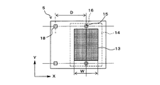
- the photomask 5 is an original of an exposure pattern formed on the film 1, and a mask pattern region 13 in which an opening of a mask pattern corresponding to the exposure pattern is formed at a substantially central portion. 1 and the mask pattern region 13 on the center line of the mask pattern region 13 parallel to the moving direction (hereinafter referred to as “X direction”) and the crossing direction (hereinafter referred to as “Y direction”) indicated by an arrow X in FIG.
- An aperture window 15 is formed outside and within the irradiation region 14 of the exposure laser beam L, and a condensing lens 16 is provided on the aperture window 15 to condense the laser beam L on the film 1.
- the alignment mark 17 (see FIG. 5) can be formed with a scratch having a fixed shape.
- An alignment window 18 is formed behind the opening window 15 in the X direction by a distance D from the center of the opening window 15. In this case, the distance D between the opening window 15 and the alignment window 18 is set to be equal to or smaller than the width W in the X direction of the mask pattern region 13 (D ⁇ W). Thereby, an exposure pattern can be formed continuously in the X direction.
- the photomask 5 is held by a mask stage 19 formed so as to be movable in the Y direction.
- Alignment means 6 is provided so that the photomask 5 and the film 1 can be moved relative to each other in the Y direction.
- the alignment means 6 is for correcting exposure misalignment, and includes an imaging means 20 and a mask stage driving means 21.
- reference numeral 29 denotes a plane reflection mirror.
- the imaging means 20 images the alignment mark 17 formed on the film 1, is a CCD camera, and is arranged with the center of the visual field aligned with the center of the alignment window 18 of the photomask 5.
- the mask stage driving means 21 moves the mask stage 19 in the Y direction, and is a combination of a stepping motor and a gear, an electromagnetic actuator, a linear motor, or the like.
- a control means 7 is provided in electrical connection with the winding motor 10, laser light source 4, imaging means 20, and mask stage driving means 21.
- the control means 7 calculates the amount of misalignment of the alignment mark 17 in the Y direction due to the movement error of the film 1, and moves the photomask 5 so as to correct this, as shown in FIG.
- the image processing unit 22, the calculation unit 23, the memory 24, the motor drive control unit 25, the light source drive unit 26, the mask stage drive control unit 27, and the control unit 28 are provided.
- the image processing unit 22 processes the image of the alignment mark 17 picked up by the image pickup means 20, and detects the center position of the alignment mark 17, for example.
- the calculator 23 calculates the amount of positional deviation between the center (reference position) of the alignment window 18 and the center of the alignment mark 17.
- the memory 24 stores the center position of the alignment mark 17 and the calculation result.
- the motor drive control unit 25 controls the rotational speed of the motor and driving and stopping.
- the light source drive unit 26 controls the power, oscillation frequency, lighting and extinguishing of the laser light source 4.
- the mask stage drive control unit 27 controls the movement direction and the movement amount of the mask stage 19 by controlling the drive of the mask stage drive means 21.
- the control unit 28 controls the driving of each element so that the entire apparatus is appropriately driven.
- step S1 the motor drive controller 25 drives the winding motor 10 to wind the film 1 in the X direction at a constant speed.
- step S2 the light source driving unit 26 is driven to turn on the laser light source 4 for a certain period of time, and the photomask 5 is irradiated with the exposure laser light L.
- This exposure laser beam L passes through the opening of the mask pattern of the photomask 5 and irradiates the film 1 to expose a pattern corresponding to the mask pattern on the film 1.
- a part of the exposure laser beam L passes through the opening window 15 of the photomask 5 and is then condensed on the film 1 by the condenser lens 16, and a fixed shape is scratched on the film 1 for alignment.
- a mark 17 is formed.
- step S3 when the film 1 is moved by the distance D and the alignment mark 17 formed on the film 1 reaches directly below the alignment window 18 of the photomask 5, the imaging means 20 passes through the alignment window 18.
- the alignment mark 17 is imaged. This captured image is subjected to image processing in the image processing unit 22, and the center position of the alignment mark 17 is detected.
- the calculation unit 23 the amount of positional deviation in the Y direction of the center of the alignment mark 17 with respect to the center (reference position) of the alignment window 18 is calculated.
- step S4 the mask stage drive controller 27 drives the mask stage drive means 21 to control the movement direction and movement amount of the mask stage 19, and the photomask 5 is moved to Y so that the amount of displacement is substantially zero. Move in the direction.
- step S5 it is determined whether or not all exposure to the film 1 has been completed.
- the process returns to step S2 to execute the next exposure, and the alignment mark 17 is formed at the same time.
- steps S5 steps S2 to S5 are executed until “YES” is determined.
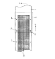
- the pattern 30 is continuously connected in the X direction and exposed on the film 1.
- the aperture window 15 and the condenser lens 16 may be provided at any position other than on the center line of the mask pattern region 13 parallel to the Y direction as long as it is an outer portion of the mask pattern region 13 in the Y direction.
- the photomask 5 is moved in the Y direction to correct the exposure misalignment.
- the film 1 side may be moved in the Y direction, and both of them are moved. May be.
- the photomask 5 is a plurality of unit masks arranged in the Y direction alternately at regular intervals so that adjacent end portions overlap each other when viewed in the X direction.
- the apparatus further includes unit mask alignment means for detecting the alignment marks between the masks formed at the end portions and adjusting the position of each unit mask so that the arrangement pitch of each unit mask becomes a constant value.
- the photomask 5 is provided with the opening window 15, the condensing lens 16 and the alignment window 18 at the outer end of the unit mask 31s at the outermost end, and is closer to the center.
- An inter-mask alignment mark 32 (indicated by ⁇ in the figure) is formed at the end, and the unit mask 31e arranged in the second and subsequent even numbers in the figure corresponds to the inter-mask alignment mark 32 in the upper end.
- the window member 34 on which the inter-mask alignment window 33 is formed is positioned and joined at a predetermined position, and the same inter-mask alignment mark 32 as above is formed at the lower end, and the third and subsequent odd numbers
- the inter-mask alignment corresponding to the inter-mask alignment mark 32 formed on the even-numbered unit mask 31e at the upper end is positioned and joined at a predetermined position, and the same inter-mask alignment mark 32 is formed at the lower end portion.
- the unit masks 31s, 31e, and 31o are arranged so that the alignment window 33 overlaps the upper and lower sides. In this case, a plurality of laser light sources 4 are provided corresponding to the unit masks 31s, 31e, and 31o.
- Each unit mask 31s, 31e, 31o is held so as to be movable in the Y direction by an individual unit mask stage (not shown). Furthermore, a camera for imaging the inter-mask alignment mark 32 is provided above each of the window members 34.
- the unit mask alignment means is constituted by the unit mask stage and the camera.
- the exposure laser beam passes through the aperture window 15 and the condenser lens 16 formed in the unit mask 31s at the outermost end.
- L is condensed on the film 1
- the alignment mark 17 is formed on the film 1
- the amount of misalignment of the alignment mark 17 in the Y direction is detected through the alignment window 18, and then the unit mask 31 s at the outermost end portion is detected. Is moved in the Y direction to correct the amount of displacement.
- the second and subsequent unit masks 31e, 31o are moved in the Y direction so that the center of the alignment mark 32 between the masks matches the center of the alignment window 33 between the masks.
- the arrangement pitch of the unit masks 31s, 31e, 31o is maintained at a constant value.
- a pattern can be exposed even on a wide plain film 1 with high positional accuracy. be able to.
- the difference between the positional deviation amounts of the two mask alignment marks 32 in the X direction can be obtained.
- the inclination angle ⁇ of the unit masks 31s, 31e, 31o with respect to the X direction can be measured, and the inclination correction of the unit masks 31s, 31e, 31o can be performed. Thereby, the position accuracy of the exposure pattern can be further improved.
- the unit mask stage of the unit mask 31s may not have a tilt correction function.
- each unit mask 31 positioned at the center of the array can be measured.
- Each unit mask 31 can be moved in the center by a certain amount in the Y direction to widen the width of the exposure area.
- the alignment mark 17 is formed by condensing the laser light L emitted from the laser light source 4 for exposure on the film 1 .
- a laser light source dedicated to the alignment mark may be provided separately.
- the condensing lens 16 in the opening window 15 of the photomask 5
- the light source for exposure is not limited to the laser light source, and may be a mercury lamp or a xenon lamp.
- the wavelength of the emitted laser light may be different between the exposure laser light source 4 and the laser light source dedicated to the alignment mark.
- the alignment window 18 is provided in the photomask 5 and the inter-mask alignment window 33 is provided in the unit masks 31s, 31e, and 31o has been described.
- the invention is not limited to this, and an alignment mark may be provided instead of the alignment window.
- FIG. 7 may be provided on the side of the mask stage 19 that positions and holds the photomask 5.
- the opening window 15 may be provided either inside the irradiation region 14 of the exposure laser beam L as shown in FIG. 5A or outside the irradiation region 14 as shown in FIG. .
- a condensing lens 16 can be provided in the aperture window 15 so that the alignment laser beam 4 can also be formed by the exposure laser light source 4 (see FIG.
- a dedicated laser light source for forming the alignment mark 17 may be provided.
- the condensing lens 16 may be omitted (see FIG. 5B).
- the pattern 30 is exposed through the mask pattern of the photomask 5 on the film 1 as shown in FIG. 8, while the mask stage 19 is exposed outside the pattern formation region in the Y direction.
- a laser beam is irradiated through the aperture window 15 to form a fixed mark on the surface of the film 1 to form an alignment mark 17, and a predetermined reference position (for example, the center position of the alignment window 18) at the rear position in the X direction. ) Is detected in the Y direction, and the mask stage 19 is moved integrally with the photomask 5 in the Y direction so as to correct the positional deviation, and the pattern 30 previously exposed is detected. Then, the next pattern 30 is exposed. By repeatedly executing this, the pattern 30 can be connected and exposed with high positional accuracy.
- the substrate is the film 1 .
- the present invention is not limited to this, and the substrate may be a plate-like member or a printed board.
Landscapes
- Physics & Mathematics (AREA)
- General Physics & Mathematics (AREA)
- Life Sciences & Earth Sciences (AREA)
- Sustainable Development (AREA)
- Exposure And Positioning Against Photoresist Photosensitive Materials (AREA)
Abstract
Description
先ず、供給リール2から表面に感光材を塗布したフィルム1を引き出して一対のガイドポール11に水平に掛け渡した後、先端部を巻取りリール3の軸に固定する。
この状態で、ステップS1においては、モータ駆動制御部25により巻取りモータ10を駆動してフィルム1をX方向に一定速度で巻き取る。
この第2の実施形態においては、フォトマスク5がY方向に複数の単位マスクをX方向に見て隣接端部が重なるように互い違いに一定間隔で配列したものであり、上記各単位マスクの隣接端部に形成したマスク間アライメントマークを検出して各単位マスクの配列ピッチが一定値となるように各単位マスクの位置調整をする単位マスクアライメント手段をさらに備えたものである。
4…レーザ光源(露光用光源)
5…フォトマスク
6…アライメント手段
13…マスクパターン領域
14…露光用レーザ光の照射領域
15…開口窓
16…集光レンズ
17…アライメントマーク
18…アライメント用窓
30…露光パターン
31,31s,31e,31o…単位マスク
32…マスク間アライメントマーク
L…レーザ光
Claims (8)
- 基板を一定方向に移動しながら、前記基板上のパターン形成領域にフォトマスクを介して予め定められたパターンを順次露光する露光方法であって、
前記基板上に前記パターンを露光する一方、基板移動方向と交差方向の前記パターン形成領域外にレーザ光を照射し、前記基板面に一定形状の傷を付けてアライメントマークを形成する段階と、
前記基板移動方向後方位置で予め定められた基準位置に対する前記アライメントマークの基板移動方向と交差方向への位置ずれを検出する段階と、
前記位置ずれを補正するように前記基板及び前記フォトマスクを相対移動する段階と、
先に露光された前記パターンの後続位置に次のパターンを露光する段階と、
を実行することを特徴とする露光方法。 - 前記フォトマスクは、前記基板移動方向と交差方向のマスクパターン領域外に、前記レーザ光を通過させて前記基板上に前記アライメントマークを形成させる開口窓を形成し、該開口窓の前記基板移動方向後方位置に前記アライメントマークを検出するためのアライメント用窓を形成したことを特徴とする請求項1記載の露光方法。
- 前記フォトマスクは、前記基板移動方向と交差方向のマスクパターン領域外にて露光用レーザ光の照射領域内に開口窓を形成し、該開口窓に集光レンズを備え、
前記露光用レーザ光により露光すると同時に該レーザ光を前記フォトマスクの集光レンズを通して前記基板に照射して前記アライメントマークを形成することを特徴とする請求項1記載の露光方法。 - 前記フォトマスクは、前記基板移動方向と交差方向に複数の単位マスクを互い違いに配列したものであり、
前記アライメントマークの位置ずれ補正段階において、前記各単位マスクの隣接端部に形成したマスク間アライメントマークを検出して各単位マスクの配列ピッチが一定値となるように各単位マスクの位置調整をすることを特徴とする請求項1~3のいずれか1項に記載の露光方法。 - 基板を一定方向に移動しながら、前記基板上のパターン形成領域にフォトマスクを介して予め定められたパターンを順次露光する露光装置であって、
前記基板上にフォトマスクを介して光源光を照射して露光させる露光用光源と、
前記基板にレーザ光を照射して基板移動方向と交差方向の前記パターン形成領域外の基板面に一定形状の傷を付けてアライメントマークを形成するレーザ光源と、
前記基板移動方向後方位置で予め定められた基準位置に対する前記アライメントマークの基板移動方向と交差方向への位置ずれを検出し、該位置ずれを補正するように前記基板及び前記フォトマスクを相対移動して露光の位置ずれを補正するアライメント手段と、
を備えたことを特徴とする露光装置。 - 前記フォトマスクは、前記基板移動方向と交差方向のマスクパターン領域外に、前記レーザ光を通過させて前記基板上に前記アライメントマークを形成させる開口窓を形成し、該開口窓の前記基板移動方向後方位置に前記アライメントマークを検出するためのアライメント用窓を形成したことを特徴とする請求項5記載の露光装置。
- 前記フォトマスクは、前記基板移動方向と交差方向のマスクパターン領域外にて露光用レーザ光の照射領域内に開口窓を形成し、該開口窓に集光レンズを備え、
前記露光用光源とレーザ光源とは、同じ波長のレーザ光を放射する一つのパルスレーザ光源であり、
前記パルスレーザ光源から放射されるレーザ光により露光すると同時に該レーザ光を前記フォトマスクの集光レンズを通して前記基板に照射し、前記アライメントマークを形成することを特徴とする請求項5記載の露光装置。 - 前記フォトマスクは、前記基板移動方向と交差方向に複数の単位マスクを互い違いに配列したものであり、
前記各単位マスクの隣接端部に形成したマスク間アライメントマークを検出して各単位マスクの配列ピッチが一定値となるように各単位マスクの位置調整をする単位マスクアライメント手段をさらに備えたことを特徴とする請求項5~7のいずれか1項に記載の露光装置。
Priority Applications (2)
| Application Number | Priority Date | Filing Date | Title |
|---|---|---|---|
| CN201180017800.9A CN102834780B (zh) | 2010-04-08 | 2011-03-03 | 曝光方法及曝光装置 |
| KR1020127029241A KR101787137B1 (ko) | 2010-04-08 | 2011-03-03 | 노광 방법 및 노광 장치 |
Applications Claiming Priority (2)
| Application Number | Priority Date | Filing Date | Title |
|---|---|---|---|
| JP2010089608A JP5382456B2 (ja) | 2010-04-08 | 2010-04-08 | 露光方法及び露光装置 |
| JP2010-089608 | 2010-04-08 |
Publications (1)
| Publication Number | Publication Date |
|---|---|
| WO2011125401A1 true WO2011125401A1 (ja) | 2011-10-13 |
Family
ID=44762362
Family Applications (1)
| Application Number | Title | Priority Date | Filing Date |
|---|---|---|---|
| PCT/JP2011/054931 Ceased WO2011125401A1 (ja) | 2010-04-08 | 2011-03-03 | 露光方法及び露光装置 |
Country Status (5)
| Country | Link |
|---|---|
| JP (1) | JP5382456B2 (ja) |
| KR (1) | KR101787137B1 (ja) |
| CN (1) | CN102834780B (ja) |
| TW (1) | TWI538148B (ja) |
| WO (1) | WO2011125401A1 (ja) |
Families Citing this family (10)
| Publication number | Priority date | Publication date | Assignee | Title |
|---|---|---|---|---|
| EP2972589B1 (en) * | 2013-03-12 | 2017-05-03 | Micronic Mydata AB | Mechanically produced alignment fiducial method and alignment system |
| CN106583934A (zh) * | 2014-06-10 | 2017-04-26 | 赵牧青 | 一种经济型激光标印系统 |
| WO2016035842A1 (ja) * | 2014-09-04 | 2016-03-10 | 株式会社ニコン | 処理システムおよびデバイス製造方法 |
| TWI571710B (zh) * | 2014-12-30 | 2017-02-21 | 力晶科技股份有限公司 | 曝光機台對準光源裝置內的模組作動監控方法及監控系統 |
| CN107077080B (zh) * | 2015-01-15 | 2019-04-26 | 株式会社村田制作所 | 曝光装置 |
| JP6554330B2 (ja) * | 2015-06-01 | 2019-07-31 | 株式会社オーク製作所 | マスクレス露光装置および露光方法 |
| JP6994806B2 (ja) * | 2017-10-31 | 2022-01-14 | 株式会社アドテックエンジニアリング | 両面露光装置及び両面露光方法 |
| JP6977098B2 (ja) * | 2020-04-07 | 2021-12-08 | キヤノン株式会社 | 露光装置、パターン形成装置及び露光方法 |
| JP2023001889A (ja) * | 2021-06-21 | 2023-01-06 | 大日本印刷株式会社 | マスクの製造方法及びマスク |
| CN116507035B (zh) * | 2023-06-28 | 2023-10-13 | 苏州维信电子有限公司 | 薄型卷料线路板及其制作方法 |
Citations (7)
| Publication number | Priority date | Publication date | Assignee | Title |
|---|---|---|---|---|
| JPH04288816A (ja) * | 1991-03-18 | 1992-10-13 | Canon Inc | アライメントマーカーの形成方法 |
| JP2001060008A (ja) * | 1999-08-23 | 2001-03-06 | Sumitomo Metal Mining Co Ltd | 露光方法およびこれを用いた電子部品の製造方法 |
| JP2008233638A (ja) * | 2007-03-22 | 2008-10-02 | Dainippon Screen Mfg Co Ltd | 描画装置および描画方法 |
| JP2009003159A (ja) * | 2007-06-21 | 2009-01-08 | Toppan Printing Co Ltd | レーザー露光方法およびレーザー露光装置 |
| JP2009058666A (ja) * | 2007-08-30 | 2009-03-19 | V Technology Co Ltd | 露光装置 |
| JP2009216861A (ja) * | 2008-03-10 | 2009-09-24 | Toray Eng Co Ltd | 帯状ワークの露光方法および露光装置 |
| JP2009265313A (ja) * | 2008-04-24 | 2009-11-12 | Nsk Ltd | スキャン露光装置並びにスキャン露光方法 |
Family Cites Families (4)
| Publication number | Priority date | Publication date | Assignee | Title |
|---|---|---|---|---|
| JP4309874B2 (ja) * | 2005-08-05 | 2009-08-05 | 株式会社ブイ・テクノロジー | 露光装置 |
| JP4754924B2 (ja) | 2005-10-07 | 2011-08-24 | 株式会社ブイ・テクノロジー | 露光装置 |
| JP5382899B2 (ja) * | 2005-10-25 | 2014-01-08 | 株式会社ブイ・テクノロジー | 露光装置 |
| JP5144992B2 (ja) * | 2007-08-27 | 2013-02-13 | 株式会社オーク製作所 | 露光装置 |
-
2010
- 2010-04-08 JP JP2010089608A patent/JP5382456B2/ja not_active Expired - Fee Related
-
2011
- 2011-03-03 CN CN201180017800.9A patent/CN102834780B/zh not_active Expired - Fee Related
- 2011-03-03 KR KR1020127029241A patent/KR101787137B1/ko not_active Expired - Fee Related
- 2011-03-03 WO PCT/JP2011/054931 patent/WO2011125401A1/ja not_active Ceased
- 2011-03-14 TW TW100108446A patent/TWI538148B/zh not_active IP Right Cessation
Patent Citations (7)
| Publication number | Priority date | Publication date | Assignee | Title |
|---|---|---|---|---|
| JPH04288816A (ja) * | 1991-03-18 | 1992-10-13 | Canon Inc | アライメントマーカーの形成方法 |
| JP2001060008A (ja) * | 1999-08-23 | 2001-03-06 | Sumitomo Metal Mining Co Ltd | 露光方法およびこれを用いた電子部品の製造方法 |
| JP2008233638A (ja) * | 2007-03-22 | 2008-10-02 | Dainippon Screen Mfg Co Ltd | 描画装置および描画方法 |
| JP2009003159A (ja) * | 2007-06-21 | 2009-01-08 | Toppan Printing Co Ltd | レーザー露光方法およびレーザー露光装置 |
| JP2009058666A (ja) * | 2007-08-30 | 2009-03-19 | V Technology Co Ltd | 露光装置 |
| JP2009216861A (ja) * | 2008-03-10 | 2009-09-24 | Toray Eng Co Ltd | 帯状ワークの露光方法および露光装置 |
| JP2009265313A (ja) * | 2008-04-24 | 2009-11-12 | Nsk Ltd | スキャン露光装置並びにスキャン露光方法 |
Also Published As
| Publication number | Publication date |
|---|---|
| KR20130102457A (ko) | 2013-09-17 |
| JP2011221241A (ja) | 2011-11-04 |
| CN102834780A (zh) | 2012-12-19 |
| JP5382456B2 (ja) | 2014-01-08 |
| TW201208032A (en) | 2012-02-16 |
| TWI538148B (zh) | 2016-06-11 |
| KR101787137B1 (ko) | 2017-10-18 |
| CN102834780B (zh) | 2016-08-03 |
Similar Documents
| Publication | Publication Date | Title |
|---|---|---|
| JP5382456B2 (ja) | 露光方法及び露光装置 | |
| JP5698831B2 (ja) | リソグラフィ装置及びデバイス製造方法 | |
| TWI684836B (zh) | 圖案描繪裝置 | |
| TWI453547B (zh) | An exposure apparatus, an exposure method, and an element manufacturing method | |
| TWI518468B (zh) | 曝光裝置 | |
| JP2010191127A (ja) | 露光装置、露光方法、及び表示用パネル基板の製造方法 | |
| US9030646B2 (en) | Exposure apparatus and photomask used therein | |
| JP2009288340A (ja) | ローラーモールド作製方法 | |
| TWI515704B (zh) | 膜片曝光方法 | |
| JP4304165B2 (ja) | 露光方法および露光装置 | |
| JP2011158718A (ja) | 露光装置、露光方法、及び表示用パネル基板の製造方法 | |
| JP4309874B2 (ja) | 露光装置 | |
| JP5180624B2 (ja) | 帯状ワークの露光方法および露光装置 | |
| JP5477862B2 (ja) | フィルム露光装置及びフィルム露光方法 | |
| TW201409184A (zh) | 照明裝置、處理裝置、及元件製造方法 | |
| JP7431532B2 (ja) | 描画方法、および、描画装置 | |
| TWI448840B (zh) | 微影裝置及器件製造方法 | |
| JP4738887B2 (ja) | 露光装置 | |
| JP2012027271A (ja) | 露光装置、露光方法、カラーフィルタの製造方法。 | |
| JP5481736B2 (ja) | フィルムの露光装置 | |
| JP2021096338A (ja) | 露光装置、露光方法、および物品製造方法 | |
| JP2006190776A (ja) | 描画装置 | |
| JP2001297969A (ja) | 露光方法及び露光装置 |
Legal Events
| Date | Code | Title | Description |
|---|---|---|---|
| WWE | Wipo information: entry into national phase |
Ref document number: 201180017800.9 Country of ref document: CN |
|
| 121 | Ep: the epo has been informed by wipo that ep was designated in this application |
Ref document number: 11765303 Country of ref document: EP Kind code of ref document: A1 |
|
| NENP | Non-entry into the national phase |
Ref country code: DE |
|
| ENP | Entry into the national phase |
Ref document number: 20127029241 Country of ref document: KR Kind code of ref document: A |
|
| 122 | Ep: pct application non-entry in european phase |
Ref document number: 11765303 Country of ref document: EP Kind code of ref document: A1 |