WO2011125398A1 - 汚染水の浄化方法 - Google Patents
汚染水の浄化方法 Download PDFInfo
- Publication number
- WO2011125398A1 WO2011125398A1 PCT/JP2011/054910 JP2011054910W WO2011125398A1 WO 2011125398 A1 WO2011125398 A1 WO 2011125398A1 JP 2011054910 W JP2011054910 W JP 2011054910W WO 2011125398 A1 WO2011125398 A1 WO 2011125398A1
- Authority
- WO
- WIPO (PCT)
- Prior art keywords
- nitrogen
- water
- nitrite
- nitrate
- iron powder
- Prior art date
- Legal status (The legal status is an assumption and is not a legal conclusion. Google has not performed a legal analysis and makes no representation as to the accuracy of the status listed.)
- Ceased
Links
Images


Classifications
-
- C—CHEMISTRY; METALLURGY
- C02—TREATMENT OF WATER, WASTE WATER, SEWAGE, OR SLUDGE
- C02F—TREATMENT OF WATER, WASTE WATER, SEWAGE, OR SLUDGE
- C02F1/00—Treatment of water, waste water, or sewage
- C02F1/70—Treatment of water, waste water, or sewage by reduction
- C02F1/705—Reduction by metals
-
- C—CHEMISTRY; METALLURGY
- C02—TREATMENT OF WATER, WASTE WATER, SEWAGE, OR SLUDGE
- C02F—TREATMENT OF WATER, WASTE WATER, SEWAGE, OR SLUDGE
- C02F1/00—Treatment of water, waste water, or sewage
- C02F1/28—Treatment of water, waste water, or sewage by sorption
- C02F1/281—Treatment of water, waste water, or sewage by sorption using inorganic sorbents
-
- C—CHEMISTRY; METALLURGY
- C02—TREATMENT OF WATER, WASTE WATER, SEWAGE, OR SLUDGE
- C02F—TREATMENT OF WATER, WASTE WATER, SEWAGE, OR SLUDGE
- C02F1/00—Treatment of water, waste water, or sewage
- C02F1/42—Treatment of water, waste water, or sewage by ion-exchange
- C02F2001/425—Treatment of water, waste water, or sewage by ion-exchange using cation exchangers
-
- C—CHEMISTRY; METALLURGY
- C02—TREATMENT OF WATER, WASTE WATER, SEWAGE, OR SLUDGE
- C02F—TREATMENT OF WATER, WASTE WATER, SEWAGE, OR SLUDGE
- C02F2101/00—Nature of the contaminant
- C02F2101/10—Inorganic compounds
- C02F2101/16—Nitrogen compounds, e.g. ammonia
- C02F2101/163—Nitrates
-
- C—CHEMISTRY; METALLURGY
- C02—TREATMENT OF WATER, WASTE WATER, SEWAGE, OR SLUDGE
- C02F—TREATMENT OF WATER, WASTE WATER, SEWAGE, OR SLUDGE
- C02F2101/00—Nature of the contaminant
- C02F2101/10—Inorganic compounds
- C02F2101/16—Nitrogen compounds, e.g. ammonia
- C02F2101/166—Nitrites
-
- C—CHEMISTRY; METALLURGY
- C02—TREATMENT OF WATER, WASTE WATER, SEWAGE, OR SLUDGE
- C02F—TREATMENT OF WATER, WASTE WATER, SEWAGE, OR SLUDGE
- C02F2103/00—Nature of the water, waste water, sewage or sludge to be treated
- C02F2103/06—Contaminated groundwater or leachate
-
- C—CHEMISTRY; METALLURGY
- C02—TREATMENT OF WATER, WASTE WATER, SEWAGE, OR SLUDGE
- C02F—TREATMENT OF WATER, WASTE WATER, SEWAGE, OR SLUDGE
- C02F2209/00—Controlling or monitoring parameters in water treatment
- C02F2209/06—Controlling or monitoring parameters in water treatment pH
Definitions
- the present invention relates to a method for effectively purifying water contaminated with a nitrogen component selected from one or both of nitrate nitrogen and nitrite nitrogen (hereinafter sometimes simply referred to as “contaminated water”).
- contaminated water a nitrogen component selected from one or both of nitrate nitrogen and nitrite nitrogen
- the present invention relates to a method for purifying contaminated water as described above quickly and easily.
- Nitrate nitrogen and nitrite nitrogen have adverse health effects. Nitrate nitrogen is reduced to nitrite nitrogen in the human body, and this nitrite nitrogen combines with hemoglobin to form metahemoglobin, which is said to cause hypoxia (methemoglobinemia) . In particular, it is said that the inside of the gastrointestinal tract of infants is weak in acidity, so that nitrate nitrogen is easily reduced by microorganisms, and methemoglobinemia is likely to occur.
- Nitrate nitrogen and nitrite nitrogen were added to the environmental standard items in February 1999 in the “Environmental standards for water pollution of groundwater” based on Article 16 of the Environmental Basic Law. Monitoring is always conducted based on the Pollution Control Law.
- Contamination of groundwater with nitrate nitrogen and nitrite nitrogen is a problem because the cause of contamination spans many branches, such as fertilization, livestock excrement, and domestic wastewater, and the contamination can be widespread.
- Nitrate nitrogen and nitrite nitrogen are basically generated by nitrogen circulation.
- organic nitrogen compounds including proteins are classified into insoluble organic nitrogen and water-soluble organic nitrogen.
- insoluble organic nitrogen is decomposed into water-soluble organic nitrogen by urea decomposing enzyme, and the water-soluble organic nitrogen is converted into ammonia.
- ammonia Since ammonia is easily dissolved in water, it exists as ammonium ions (ammonia nitrogen) in water. Ammonium ions generate nitrite ions (nitrite nitrogen) by ammonia oxidizing bacteria such as nitrosomonas in an aerobic atmosphere. Next, nitrite ions generate nitrate ions (nitric nitrogen) by nitrite oxidizing bacteria such as nitrobacter in an aerobic atmosphere. Nitrate nitrogen and nitrite nitrogen are thus present as ions in water.
- Methods for purifying water (contaminated water) containing nitrate nitrogen and nitrite nitrogen are roughly classified into physicochemical methods and biochemical methods.
- ion exchange methods, electrodialysis methods, reverse osmosis membrane methods, catalytic denitrification methods and the like are known as physicochemical methods.
- heterotrophic denitrification method, autotrophic denitrification method and the like are known as biochemical methods.
- the ion exchange method is a method of decomposing and removing nitrate nitrogen and nitrite nitrogen, which are anions, using a strongly basic anion exchange resin.
- the ion exchange method has a fundamental problem that equipment costs increase and a large amount of sodium chloride is generated due to the use of a large amount of sodium chloride for regeneration of the ion exchange resin, which requires treatment. There is.
- Electrodialysis is a method in which an anion exchange membrane is passed through to separate nitrate nitrogen and nitrite nitrogen.
- the reverse osmosis membrane method is located on one side of a semipermeable membrane, and by applying pressure to water containing nitrate nitrogen and nitrite nitrogen, water that does not contain nitrate nitrogen and nitrite nitrogen is semipermeable membrane. This is a method of separating nitrate nitrogen and nitrite nitrogen from water by permeating the other side.
- Both the electrodialysis method and the reverse osmosis membrane method have a problem that the facility cost and the maintenance cost increase, and the waste water treatment in which nitrate nitrogen and nitrite nitrogen have a high concentration is required.
- heterotrophic denitrification method as a biochemical method, nitrate-containing nitrogen and nitrite are filtered by filtering water containing nitrate nitrogen and nitrite nitrogen through a granular filter layer on which heterotrophic denitrifying bacteria adhere and grow. Reducing nitrogen to nitrogen gas.
- the same treatment as in the heterotrophic denitrification method is performed on the filter layer on which sulfur denitrifying bacteria, which are autotrophic bacteria, are attached and grown.
- the treatment efficiency depends on the water temperature (ie, temperature), and in particular, the autotrophic denitrification method has a slow reaction rate and easily produces sulfuric acid as a by-product. There is a problem. In addition, there is a drawback that a high level of technology is required for operation management of the apparatus.
- Patent Document 1 discloses that a purification wall containing denitrifying bacteria and biodegradable polymers is applied to a groundwater layer contaminated with nitric acid and phosphoric acid.
- Patent Document 2 proposes to use a reducing agent in combination with the above method, and this reducing agent anaerobically removes groundwater so that the denitrifying bacteria can easily perform denitrifying activities in an anaerobic atmosphere. It is for making sex atmosphere.
- Patent Document 1 has a basic problem that the purification process takes too much time.
- Patent Document 2 in addition to the above problems, microbial degradation may occur such that degradation of the biodegradable polymer is inhibited by the presence of iron powder, and the amount of iron powder added is small.
- the effect of iron powder varies (effectively and ineffectively) depending on the type of biodegradable polymer. is there.
- denitrifying bacteria present in the actual treated soil and purification wall
- denitrification is sufficiently performed in the method using the denitrification bacteria and the purification wall containing biodegradable polymers.
- the total amount of organic carbon in the treated water increases due to decomposition of the biodegradable polymer, and secondary treatment such as activated carbon treatment or ozone treatment may be required.
- nitrate nitrogen and nitrite nitrogen are once reduced to ammonia nitrogen with various reducing agents, and then ammonia nitrogen is purified. If such technology reduces to ammonia nitrogen, the subsequent purification process is easy.
- Patent Document 3 uses ferrous sulfate (FeSO 4 ), ferrous chloride (FeCl 2 ) and other ferrous compounds as a reducing agent, and nitrate nitrogen and nitrite in contaminated water.
- FeSO 4 ferrous sulfate
- FeCl 2 ferrous chloride
- Patent Document 4 iron in various forms (powder, granules, plates, etc.) is used as a reducing agent, and nitrate nitrogen and nitrous acid nitrogen are brought into contact with nitrate nitrogen and nitrite nitrogen.
- a method for reducing nitrate nitrogen has also been proposed.
- the present invention has been made under the circumstances as described above, and its purpose is to quickly and surely remove a nitrogen component selected from one or both of nitrate nitrogen and nitrite nitrogen to prevent contamination. It is to provide a useful method for purifying water.
- the method of the present invention that has been able to solve the above-mentioned problem is to bring water contaminated with a nitrogen component selected from one or both of nitrate nitrogen and nitrite nitrogen into contact with iron powder containing sulfur, and the nitrogen component It has a gist in that water is purified by reducing ammonia nitrogen to remove ammonia nitrogen from water containing ammonia nitrogen.
- the content of sulfur in the iron powder used in the method of the present invention is preferably 0.3% by mass or more and 2.0% by mass or less.
- the average particle diameter (median diameter) of the iron powder is preferably 1 ⁇ m or more and 10 mm or less.
- nitrogen components present in nature There are two possible forms of nitrogen components present in nature.
- nitrogen dissolved in rainwater becomes ammoniacal nitrogen and is further oxidized to nitrate nitrogen.
- This nitrate nitrogen penetrates into the soil with rainwater.
- Rainwater has a pH of about 5 to 6 and a redox potential [standard hydrogen electrode (SHE) standard: the same applies hereinafter) +0.8 to +1.0 V. In this range, ammonia nitrogen is reduced to nitrate nitrogen.
- SHE standard hydrogen electrode
- Biological pathway is a pathway in which ammonia nitrogen is changed to nitrate nitrogen or nitrite nitrogen by bacteria.
- Nitrite nitrogen is intermediately produced in the process in which ammonia nitrogen is oxidized to nitrate nitrogen. Since nitrite nitrogen has a higher oxidation reaction rate than ammonia nitrogen, nitrite nitrogen usually does not accumulate in soil. However, when the activity of nitrate bacteria is suppressed due to the influence of pH or the like, nitrite nitrogen may accumulate in the soil.
- the second form of nitrogen component is the phenomenon that it is adsorbed by clay minerals and humus soil in the soil and remains ammoniacal nitrogen. This is because ammonia nitrogen is positively charged, and clay minerals and humus soil in the soil are negatively charged. Among the forms of nitrogen, ammonia nitrogen is easier to remove than nitrate nitrogen or nitrite nitrogen.
- nitrate nitrogen and nitrite nitrogen (a nitrogen component selected from one or both of nitrate nitrogen and nitrite nitrogen) that have penetrated into the soil while considering the above-described situation, We examined how quickly and reliably it can be rendered harmless from various angles.
- nitrate nitrogen and nitrite nitrogen a nitrogen component selected from one or both of nitrate nitrogen and nitrite nitrogen
- the present inventors have further investigated a reducing agent that reduces nitrate nitrogen and nitrite nitrogen to ammonia nitrogen, and found that it is extremely useful to use iron powder containing sulfur. Was completed.
- the sulfur content in the iron powder is preferably 0.3% by mass or more.
- sulfur content shall be 2.0 mass% or less, and by doing in this way, reduction efficiency can be improved, after suppressing the cost increase of a reducing agent.
- the more preferable lower limit of the sulfur content is 0.6% by mass or more, more preferably 0.8% by mass or more, and the more preferable upper limit is 1.5% by mass or less, and further preferably 1.3% by mass or less. is there.
- the oxidation-reduction potential should be controlled to be +0.4 V or less in the pH range of 5 to 6 has been obtained. . Therefore, it seemed that the reducing agent should have an oxidation-reduction potential of +0.4 V or less based on the standard hydrogen electrode.
- metal whose oxidation-reduction potential is +0.4 V or less in addition to iron, copper, bismuth, lead, tin, nickel, cobalt, titanium, indium, cadmium, gallium, chromium, zinc, manganese, aluminum, beryllium, magnesium, Various things such as sodium, calcium, strontium, barium, cesium, rubidium, potassium, lithium and the like can be considered. Also.
- alloys whose oxidation-reduction potential is +0.4 V or less include iron-based alloys such as cast iron, carbon steel, nickel chrome steel, nickel chrome molybdenum steel, chrome steel, chrome molybdenum steel, manganese steel, bronze, red brass, brass, etc. Copper-base alloys, lead-tin alloys such as solder, etc. are also conceivable.
- Copper and zinc have little effect on the human body, but may have an effect on animals and plants. Bismuth is expensive and has the potential to be harmful. Lead, cadmium, and chromium may cause secondary contamination due to their elution. Tin can cause tin pneumonia by aspirating the dust. Nickel and cobalt are expensive. Indium and beryllium are carcinogenic. Gallium has a high melting point and has a problem in handling.
- manganese is a relatively highly reactive powder, it reacts with water and oxygen in the air to form oxides, so the amount of manganese ions eluted into water is reduced, and there is a problem with the sustainability of the reduction reaction. .
- an alloy that forms a passive state such as chromium-containing stainless steel, has a problem in the sustainability of the reduction reaction because the passive state inhibits the elution of the metal into water.
- iron powder containing a predetermined amount of sulfur is used as a reducing agent.
- the iron powder used as a reducing agent in the present invention has a large reaction area (that is, a large specific surface area), so that it is not only powdery but also has a certain size (for example, Granules) can also be used.
- the size is preferably about 1 ⁇ m or more and 10 mm or less in terms of handleability in terms of average particle diameter (mass basis: median diameter). More preferably, it is 10 ⁇ m or more and 5 mm or less.
- the purification method of the present invention includes (1) a step of reducing nitrate nitrogen or nitrite nitrogen to ammonia nitrogen, and (2) a step of removing ammonia nitrogen.
- a nitrogen component selected from one or both of contaminated water is added to a layer filled with a reducing agent (reducing agent packed layer).
- a reducing agent reducing agent packed layer.
- powder particles for example, natural minerals such as silica sand
- the reducing agent packed layer shown in FIG. 1 powder particles (for example, natural minerals such as silica sand) for increasing the porosity of the packed layer are used together with the reducing agent in order to ensure water permeability. Also good. Further, when passing contaminated water, either an upward flow that flows upward into the reactor or a downward flow that flows downward into the reactor can be employed.
- stirrer when the stirring tank as shown in FIG. 2 is employed, a stirrer may be installed as shown in order to increase the reactivity.
- This stirrer can employ either a wing-like one or a conveyor-like one.
- the settling tank shown in FIG. 2 is for preventing the floating reducing agent from being discharged to the outside, and is provided side by side as necessary.
- step (2) at least a conventionally known method such as a microbial denitrification method, an ammonia stripping method, a discontinuous point chlorine addition method, an ion exchange method, a zeolite adsorption method, a membrane separation method, or a catalytic denitrification method is used.
- Ammonia nitrogen is removed by one or more methods, and is then gasified and removed.
- adsorbent having a cation exchange ability it is also effective to employ a configuration in which contaminated water is brought into contact with an adsorbent having a cation exchange ability while contacting with a reducing agent (iron powder). Reduction of nitrogen and nitrite nitrogen to ammonia nitrogen and removal of ammonia nitrogen can be performed in parallel.
- adsorbent having cation exchange ability include natural minerals such as zeolite, silica gel, activated alumina, cation exchange resin and the like.
- At least an iron component is contained, and the reduction reaction proceeds according to the following formula (1).
- hydroxide ions are concentrated and the pH rises to 9 or more.
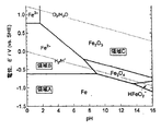
- the influence of pH on the passive potential of Fe is shown in FIG. 3 (in the figure, region A shows a stable region of Fe, region B shows a corrosion region, and region C shows a passive region).
- the reducing agent tends to be passive and the reduction reaction does not proceed easily.
- chlorine that is, by adopting the discontinuous point chlorine addition method
- hydrogen ions are generated, so that the pH increase can be suppressed, and one of nitrate nitrogen and nitrite nitrogen or
- the reduction from the nitrogen component selected from both to ammonia nitrogen and the removal of ammonia nitrogen can be performed in parallel, which is preferable. From this point of view, it is preferable to control the pH at the time of contacting the contaminated water and the reducing agent to 5-6.
- Example 1 (Reduction test from nitrate nitrogen to ammonia nitrogen) Ion exchange water: To 2,000 mL, 243 mg of sodium nitrate reagent (special grade: manufactured by Wako Pure Chemical Industries, Ltd.) was added and stirred using a stirrer to obtain an aqueous solution (hereinafter referred to as “raw water”). 250 mL of this raw water is put into a 500 mL polyethylene container, and 50 g of iron powder with different sulfur content is added as a reducing agent, and nitrogen gas is purged at a flow rate of 500 L / min for 3 minutes, and then at 25 ° C. The mixture was shaken for 96 hours at 140 rpm on a shaker.
- raw water aqueous solution
- Nitrite nitrogen was analyzed using a TNT reagent by a diazotization method.
- Example 2 (Reduction test from nitrate nitrogen to ammonia nitrogen) Ion-exchanged water: 121 mL of sodium nitrate reagent (special grade: manufactured by Wako Pure Chemical Industries, Ltd.) was added to 1000 mL, stirred with a stirrer, and dissolved (hereinafter referred to as “raw water”). 250 mL of this raw water was placed in a 500 mL polyethylene container, and experiment No. 1 was used as a reducing agent. 125 g of iron powder having a sulfur content of 1.20% by mass and an average particle size of 54 ⁇ m used in No. 5 was added and purged with nitrogen gas at a flow rate of 500 L / min for 3 minutes, and then 140 rpm on a horizontal shaker at 25 ° C. Shake for 48 hours.
- raw water 121 mL of sodium nitrate reagent (special grade: manufactured by Wako Pure Chemical Industries, Ltd.) was added to 1000 mL, stirred with a stirrer
- Example 3 Ammonia nitrogen adsorption test with reducing agent from nitrate nitrogen to ammonia nitrogen and cation adsorbent 250 mL of the raw water is put into a 500 mL polyethylene container, and 62.5 g of the same iron powder as used in Example 2 is used as a reducing agent, and zeolite (trade name “ZO # 2070”: Nitto) as a cation adsorbent. After adding 62.5 g of powdered product and purging nitrogen gas at a flow rate of 500 L / min for 3 minutes in the same manner as in Examples 1 and 2, the mixture was shaken at 25 ° C. with a horizontal shaker at 140 rpm for 48 hours. .
- the concentrations of nitrate nitrogen and nitrite nitrogen in the raw water and the solutions after shaking in Examples 2 and 3 were measured in the same manner as in Example 1.
- the concentration of ammonia nitrogen was also measured by the following method. The results are shown in Table 2 below together with the total amount of nitrate nitrogen, nitrite nitrogen and ammonia nitrogen (total nitrogen).
- ammonia nitrogen concentration measurement The concentration of ammoniacal nitrogen was analyzed by a distillation-titration method (JIS K 0102 42.1, 42.3). In addition, each nitrogen concentration was analyzed for the solution after shaking by the filtrate which filtered with the suction filter [Omnipore membrane (model number: JMWP04700)].
- Example 2 nitrate nitrogen was reduced from 20.3 mg / L to 1.2 mg / L, ammonia nitrogen was 18.0 mg / L, and nitrate nitrogen was reduced to ammonia nitrogen. I understand that.
- Example 3 nitrate nitrogen remained at 7.2 mg / L, but total nitrogen was reduced from 20.3 mg / L to 7.2 mg / L. This difference in the total nitrogen concentration is considered to be due to the adsorption of ammonia nitrogen on zeolite, which is a cation adsorbent. It can be seen that this method can reduce the total nitrogen concentration.
- the nitrogen component (nitrogen component selected from one or both of nitrate nitrogen and nitrite nitrogen) contained in the contaminated water is converted into ammonia nitrogen.
Landscapes
- Life Sciences & Earth Sciences (AREA)
- Hydrology & Water Resources (AREA)
- Engineering & Computer Science (AREA)
- Environmental & Geological Engineering (AREA)
- Water Supply & Treatment (AREA)
- Chemical & Material Sciences (AREA)
- Organic Chemistry (AREA)
- Treatment Of Water By Oxidation Or Reduction (AREA)
- Treatment Of Water By Ion Exchange (AREA)
- Water Treatment By Sorption (AREA)
Abstract
硝酸性窒素および亜硝酸性窒素の一方または両方から選ばれる窒素成分に汚染された水を、硫黄を含有する鉄粉と接触させ、前記窒素成分をアンモニア性窒素に還元し、アンモニア性窒素を含有する水からアンモニア性窒素を除去することによって、水を浄化する構成を採用し、硝酸性窒素および亜硝酸性窒素の一方または両方から選ばれる窒素成分を、汚染された水から迅速且つ確実に除去して、水の浄化を行なうための有用な方法を提供する。
Description
本発明は、硝酸性窒素および亜硝酸性窒素の一方または両方から選ばれた窒素成分に汚染された水(以下、単に「汚染水」と呼ぶことがある)を効果的に浄化する方法に関するものであり、特に上記のような汚染水を迅速且つ簡便に浄化する方法に関するものである。
硝酸性窒素および亜硝酸性窒素は、健康へ悪影響を及ぼすことが指摘されている。硝酸性窒素は、人体内で亜硝酸性窒素に還元され、この亜硝酸性窒素がヘモグロビンと結合してメタヘモグロビンを形成することから、酸素欠乏症(メトヘモグロビン血症)を引き起こすと言われている。特に、乳幼児の胃腸内部は酸度が弱いため、微生物による硝酸性窒素の還元が起きやすく、メトヘモグロビン血症にかかりやすいと言われている。
硝酸性窒素および亜硝酸性窒素は、環境基本法第16条に基づく、「地下水の水質汚濁に関わる環境基準」において、平成11年2月に環境基準項目に追加され、平成11年4月から水質汚濁防止法に基づく常時監視が行なわれている。
硝酸性窒素および亜硝酸性窒素による地下水汚染は、施肥、家畜排泄物、生活排水等、汚染原因が多枝に亘り、また汚染が広範囲に及ぶことがあるから、問題である。
硝酸性窒素および亜硝酸性窒素は、基本的に窒素循環によって生成されることになる。例えば、蛋白質を始めとする有機窒素化合物は、不溶性有機窒素と水溶性有機窒素に分けられる。このうち、不溶性有機窒素は、尿素分解酵素によって水溶性有機窒素に分解され、水溶性有機窒素はアンモニアに変化する。
アンモニアは、水に容易に溶けることから、水中ではアンモニウムイオン(アンモニア性窒素)として存在することになる。アンモニウムイオンは、好気性雰囲気においてニトロソモナス属等のアンモニア酸化菌により、亜硝酸イオン(亜硝酸性窒素)を生成する。次いで、亜硝酸イオンは、好気性雰囲気でニトロバクター属等の亜硝酸酸化菌により、硝酸イオン(硝酸性窒素)を生成することになる。硝酸性窒素および亜硝酸性窒素は、このように、水中ではイオンとして存在することになる。
硝酸性窒素および亜硝酸性窒素を含有する水(汚染水)の浄化方法は、物理化学的方法と生物化学的方法に大別される。このうち、物理化学的方法としては、イオン交換法、電気透析法、逆浸透膜法、触媒脱窒法等が知られている。一方、生物化学的方法としては、従属栄養性脱窒法、独立栄養性脱窒法等が知られている。
前記イオン交換法は、強塩基性陰イオン交換樹脂を用いて、陰イオンである硝酸性窒素、亜硝酸性窒素を分解除去する方法である。しかし、イオン交換法は、設備費が嵩むことや、イオン交換樹脂の再生に多量の塩化ナトリウムを使用することにより、高濃度の塩化ナトリウが発生し、その処理が必要になるという根本的な問題がある。
電気透析法は、陰イオン交換膜を通水させ、硝酸性窒素および亜硝酸性窒素を分離する方法である。逆浸透膜法は、半透膜の片側に存在し、硝酸性窒素および亜硝酸性窒素を含有する水に圧力を加えることによって、硝酸性窒素および亜硝酸性窒素を含まない水を半透膜の反対側に浸透させ、硝酸性窒素および亜硝酸性窒素と水を分離する方法である。これら電気透析法、逆浸透膜法は、いずれも設備費、維持費が嵩むと共に、硝酸性窒素、亜硝酸性窒素が高濃度となった廃水処理が必要になるという問題もある。
生物化学的方法としての従属栄養性脱窒法では、従属栄養性脱窒菌が付着および増殖した粒状濾層で、硝酸性窒素および亜硝酸性窒素を含有する水を濾過し、硝酸性窒素および亜硝酸性窒素を窒素ガスに還元する。また、独立栄養性脱窒法では、独立栄養菌である硫黄脱窒菌を付着および増殖した濾層で、従属栄養菌性脱窒法と同様に処理する。これら従属栄養性脱窒法、独立栄養性脱窒法では、処理効率が水温(即ち、気温)に依存するという問題や、特に独立栄養性脱窒法では反応速度が遅く、しかも副産物として硫酸が生成しやすいという問題がある。加えて、装置の運転管理に当り、高度の技術が必要になるという欠点がある。
汚染水の浄化方法として、これまでにも様々提案されており、例えば、特許文献1には、脱窒菌および生分解性高分子を含む浄化壁を、硝酸およびリン酸によって汚染された地下水層に埋設することによって、汚染された地下水を浄化する方法が提案されている。また、特許文献2には、上記の方法に加え、還元剤を併用することが提案されており、この還元剤は、脱窒菌が嫌気性雰囲気において脱窒活動を行ない易いように、地下水を嫌気性雰囲気にするためのものである。
しかしながら、上記特許文献1に示される技術では、浄化処理に時間がかかり過ぎるという基本的な問題がある。また、特許文献2の技術では、上記の問題に加え、鉄粉末の存在によって生分解性高分子の分解が阻害される様な微生物分解が生じることもあり、また鉄粉の添加量が少ない方が脱窒に要するカラム内の距離が少なくて済むという逆転現象が生じており、生分解性高分子の種類によっては、鉄粉の影響が異なる(有効にも無効にも作用する)という問題がある。
しかも、実際の処理土壌や浄化壁に存在する脱窒菌種類や量は様々であり、脱窒菌および生分解性高分子を含む浄化壁を用いる方法では、場合によっては、脱窒が十分に行なわれないという問題が生じ、或は生分解性高分子の分解により、処理水中の全有機炭素量が増加し、活性炭処理やオゾン処理等の二次処理が必要となることがある。
一方、硝酸性窒素および亜硝酸性窒素を各種還元剤によって、一旦アンモニア性窒素まで還元し、その後アンモニア性窒素を浄化する方法も提案されている。こうした技術は、アンモニア性窒素まで還元すれば、その後の浄化工程が容易である。
こうした技術として、例えば特許文献3には、硫酸第一鉄(FeSO4)や塩化第一鉄(FeCl2)等の第一鉄化合物を還元剤として用い、汚染水中の硝酸性窒素および亜硝酸性窒素を還元する方法が提案されている。また、特許文献4には、各種形態(粉末状、粒状、板状等)の鉄を還元剤として用い、これと硝酸性窒素および亜硝酸性窒素とを接触させることによって、硝酸性窒素および亜硝酸性窒素を還元する方法も提案されている。
しかしながら、これらの技術で提案された還元剤は、硝酸性窒素および亜硝酸性窒素の還元能力が十分なものとは言えず、更なる改良が望まれている。また、上記特許文献3の技術では、汚泥処理をする必要があり、工程が煩雑となるという問題もある。
本発明は上記の様な状況の下でなされたものであって、その目的は、硝酸性窒素および亜硝酸性窒素の一方または両方から選ばれる窒素成分を、迅速且つ確実に除去して、汚染水の浄化を行なうための有用な方法を提供することにある。
上記課題を解決することのできた本発明方法は、硝酸性窒素および亜硝酸性窒素の一方または両方から選ばれる窒素成分に汚染された水を、硫黄を含有する鉄粉と接触させ、前記窒素成分をアンモニア性窒素に還元し、アンモニア性窒素を含有する水からアンモニア性窒素を除去することによって、水を浄化する点に要旨を有するものである。
本発明方法で用いる鉄粉中の硫黄の含有量は、0.3質量%以上、2.0質量%以下が好ましい。また鉄粉の平均粒径(メジアン径)は1μm以上、10mm以下が好ましい。
汚染された水を、硫黄を含有する鉄粉と接触させる際にには、水のpHを5~6に制御することや、外部の酸素を遮断することも好ましい要件である。
本発明方法においては、前記汚染された水を、前記鉄粉と接触させつつ、陽イオン交換能を有する吸着剤にも接触させることが有用であり、これによって前記窒素成分からアンモニア性窒素への還元と並行して、アンモニア性窒素の除去も行なえる。
本発明によれば、硫黄を含有する鉄粉と汚染水を接触させることによって、硝酸性窒素および亜硝酸性窒素の一方または両方から選ばれる窒素成分を迅速且つ確実に除去することが可能になり、汚染水の浄化を行なうための有用な方法が実現できた。
自然界に存在する窒素成分の形態は、以下に示す2通りが考えられる。1つは、アンモニアが、硝酸性窒素または亜硝酸性窒素に変化して存在する形態であり、この形態に至る経路は更に化学的経路と生物学的経路の2通りに分けられる。化学的経路では、雨水に溶解した窒素がアンモニア性窒素となり、更に硝酸性窒素に酸化される。この硝酸性窒素は、雨水と共に土中に浸透する。雨水はおよそpH5~6、酸化還元電位[標準水素電極(SHE)基準:以下同じ]+0.8~+1.0Vの範囲にあり、この範囲では、アンモニア性窒素が硝酸性窒素に還元される。
生物学的経路は、アンモニア性窒素がバクテリアによって硝酸性窒素または亜硝酸性窒素に変化する経路である。アンモニア性窒素が硝酸性窒素に酸化される過程で中間的に生成されるのが亜硝酸性窒素である。アンモニア性窒素よりも亜硝酸性窒素の方が、酸化反応速度が大きいので、通常、亜硝酸性窒素が土壌中に集積することはない。しかしながら、pH等の影響によって、硝酸菌の活性が抑制されると、亜硝酸性窒素が土壌中に集積することがある。
窒素成分の存在形態の2つめとしては、土壌中の粘土鉱物や腐植土に吸着され、アンモニア性窒素のままに留まる現象である。これは、アンモニア性窒素は正電荷を帯びており、土壌中の粘土鉱物や腐植土等は負に帯電しているためである。窒素の存在形態のうち、アンモニア性窒素の方が、硝酸性窒素または亜硝酸性窒素よりも除去しやすいものとなる。
本発明者らは、上記のような状況を考慮しつつ、土壌中に浸透した硝酸性窒素および亜硝酸性窒素(硝酸性窒素および亜硝酸性窒素の一方または両方から選ばれる窒素成分)を、如何に迅速且つ確実に無害化できるかを様々な角度から検討した。硝酸性窒素および亜硝酸性窒素を、浄化しやすいアンモニア性窒素に還元し、得られたアンモニア性窒素を含む汚染水から、アンモニア性窒素を浄化(アンモニア性窒素の窒素ガス化)することによって、汚染水を浄化することは知られている(前記特許文献3、4)。しかしながら、これまで提案されている還元剤では、その還元能力に限界があった。
本発明者らは、硝酸性窒素および亜硝酸性窒素をアンモニア性窒素に還元する還元剤について、更に検討したところ、硫黄を含有する鉄粉を用いることが極めて有用であることを見出し、本発明を完成した。
本発明方法では、硝酸性窒素および亜硝酸性窒素をアンモニア性窒素に還元する還元剤として、硫黄を含有する鉄粉を用いることが重要である。還元剤としての効果を有効に発揮させるためには、鉄粉中の硫黄含有量は0.3質量%以上であることが好ましい。また、硫黄含有量を2.0質量%以下とすることが好ましく、このようにすることで、還元剤のコストアップを抑制した上で、還元効率を高めることができる。硫黄含有量のより好ましい下限は0.6質量%以上、更に好ましくは0.8質量%以上であり、より好ましい上限は1.5質量%以下であり、更に好ましくは1.3質量%以下である。
硝酸性窒素および亜硝酸性窒素をアンモニア性窒素に還元するためには、pH5~6の範囲で、酸化還元電位を+0.4V以下となるように制御すれば良いとの着想が得られている。従って、還元剤は、標準水素電極基準の酸化還元電位が+0.4V以下であれば良いかの様に思われた。
酸化還元電位が+0.4V以下である金属としては、鉄の他、銅、ビスマス、鉛、錫、ニッケル、コバルト、チタン、インジウム、カドミウム、ガリウム、クロム、亜鉛、マンガン、アルミニウム、ベリリウム、マグネシウム、ナトリウム、カルシウム、ストロンチウム、バリウム、セシウム、ルビシウム、カリウム、リチウム等、様々なものが考えられる。また。酸化還元電位が+0.4V以下となる合金としては、鋳鉄、炭素鋼、ニッケルクロム鋼、ニッケルクロムモリブデン鋼、クロム鋼、クロムモリブデン鋼、マンガン鋼等の鉄基合金、青銅、丹銅、黄銅等の銅基合金、半田等の鉛-錫合金等も考えられる。
しかしながら、酸化還元電位が+0.4V以下であるという要件だけを満足させても、還元剤としての能力には限界があることが判明した。加えて、これらの還元剤は、安全性やコストの点で下記のような問題がある。
銅、亜鉛は、人体への影響は少ないものの、動・植物への影響の可能性がある。ビスマスは高価であり、その有害性がある可能性を持っている。鉛、カドミウム、クロムは、それらの溶出による二次汚染の恐れがある。錫は、その発塵を吸引することによって、錫肺症を引き起こす恐れがある。ニッケル、コバルトは高価である。インジウム、ベリリウムは、発ガン性がある。ガリウムは融点が高く、その取り扱い性に問題がある。
チタン、アルミニウム、マグネシウム、ナトリウム、カルシウム、ストロンチウム、バリウム、セシウム、ルビシウム、カリウム、リチウムは空気に接触させることにより発火する、或は水に接触させることにより発火し、または可燃性のガスを発生させる危険を有し、取り扱いに高度の技術を要する。マンガンは、比較的反応性の高い粉末にすると、空気中の水、酸素と反応して酸化物となるため、マンガンイオンの水への溶出量が少なくなり、還元反応の持続性に問題がある。
一方、クロムを含有するステンレス鋼のように不動態を形成する合金は、不動態が金属の水中への溶出を阻害するため、還元反応の持続性に問題があり、不動態を形成しない合金が好ましい。そこで、本発明では、所定量の硫黄を含む鉄粉を還元剤として用いた。
本発明で還元剤として用いる鉄粉は、反応面積が大きいことという理由(即ち、比表面積が大きいこと)から、粉末状のものは勿論のこと、或る程度粒が大きくなっているもの(例えば、顆粒状のもの)も用いることができる。その大きさは取り扱い性の面から平均粒径(質量基準:メジアン径)で1μm以上、10mm以下程度であることが好ましい。より好ましくは10μm以上、5mm以下である。
本発明の浄化方法は、(1)硝酸性窒素や亜硝酸性窒素をアンモニア性窒素に還元する工程と、(2)アンモニア性窒素を除去する工程を含むものである。
上記(1)の工程は、例えば図1に示すように、還元剤を充填した層(還元剤充填層)に汚染水(硝酸性窒素および亜硝酸性窒素の一方または両方から選ばれる窒素成分を含有する水)を導入部から通水して還元し、アンモニア性窒素を含有する水(アンモニア性窒素含有水)として取り出す(排出部)構成を採用することによって達成される。或は、図2に示すように、還元剤を分散させた撹拌槽内に汚染水(硝酸性窒素および亜硝酸性窒素の一方または両方から選ばれる窒素成分を含有する水)を導入部から通水し、アンモニア性窒素含有水として取り出す(排出部)構成を採用することによっても達成される。いずれの構成を採用する場合でも、外部の酸素を遮断する構成を採用することが好ましい。こうした構成として、窒素パージ等を行なって、外部からの空気を遮断する構成が挙げられる。
前記図1に示した還元剤充填層には、通水性確保のために、充填層の空隙率を高めるための粉末粒体(例えば、珪砂等の天然鉱物)を還元剤と併用するようにしても良い。また、汚染水の通水に当たっては、反応器内に上向きに通水する上向流、反応器内に下向きに通水する下向流のいずれも採用できる。
また、前記図2に示したような撹拌槽を採用する場合には、その反応性を高めるために、図示したように撹拌機を設置しても良い。この撹拌機は、羽状のものやコンベア状のもののいずれも採用できる。また、図2に示した沈殿槽は、浮遊還元剤を外部に排出させないためのものであって、必要によって併設される。
次に、上記(2)の工程では、微生物脱窒法、アンモニアストリッピング法、不連続点塩素添加法、イオン交換法、ゼオライト吸着法、膜分離法、触媒脱窒法等、従来公知の方法の少なくとも1種以上の方法によって、アンモニア性窒素が取り出され、その後窒素ガス化されて除去される。
本発明では、汚染水を還元剤(鉄粉)を接触させつつ、陽イオン交換能を有する吸着剤にも接触させる構成を採用することも有効であり、こうした構成を採用することによって、硝酸性窒素および亜硝酸性窒素からアンモニア性窒素への還元と、アンモニア性窒素の除去を並行して行なうことができる。上記陽イオン交換能を有する吸着剤としては、ゼオライト等の天然鉱物、シリカゲル、活性アルミナ、陽イオン交換樹脂等が挙げられる。
本発明で用いる還元剤として、少なくとも鉄成分を含み、還元反応は下記(1)式に従って進行し、時間の経過と共に水酸化物イオンが濃縮し、pHが9以上に上昇することになる。Feの不動態電位に及ぼすpHの影響を図3に示す(図中、領域AはFeの安定域、領域Bは腐食域、領域Cは不動態域を、夫々示す)。
2Fe+O2+2H2O→2Fe2++4OH- …(1)
2Fe+O2+2H2O→2Fe2++4OH- …(1)
pHが上昇することによって、還元剤が不動態となりやすくなり、還元反応が進みにくくなることが考えられる。しかしながら、処理水に塩素を加えることによって(即ち、不連続点塩素添加法を採用することによって)、水素イオンが発生するため、pH上昇を抑制でき、硝酸性窒素および亜硝酸性窒素の一方または両方から選ばれる窒素成分からアンモニア性窒素への還元と、アンモニア性窒素の除去を並行して行なうことができるようになるので、好ましい。こうした観点からして、汚染水と還元剤を接触する際のpHは5~6に制御することが好ましい。
以下、実施例を挙げて本発明の構成および作用効果をより具体的に説明するが、本発明はもとより下記実施例によって制限を受けるものではなく、前・後記の趣旨に適合し得る範囲で適当に変更して実施することも可能であり、それらはいずれも本発明の技術的範囲に包含される。
[実施例1]
(硝酸性窒素からアンモニア性窒素への還元試験)
イオン交換水:2000mLに、硝酸ナトリウム試薬(特級:和光純薬製)を243mg添加し、スターラを用いて撹拌し、水溶液とした(以下、「原水」と呼ぶ)。この原水を、500mLのポリエチレン製容器に250mL入れ、更に還元剤として、硫黄含有量を変えた鉄粉を各50g添加し、窒素ガスを流量500L/minで3分間パージした後、25℃で水平振とう機で140rpmにて96時間振とうした。
(硝酸性窒素からアンモニア性窒素への還元試験)
イオン交換水:2000mLに、硝酸ナトリウム試薬(特級:和光純薬製)を243mg添加し、スターラを用いて撹拌し、水溶液とした(以下、「原水」と呼ぶ)。この原水を、500mLのポリエチレン製容器に250mL入れ、更に還元剤として、硫黄含有量を変えた鉄粉を各50g添加し、窒素ガスを流量500L/minで3分間パージした後、25℃で水平振とう機で140rpmにて96時間振とうした。
原水(振とう前のもの)、24時間振とう後、48時間振とう後、および96時間振とう後に、溶液の硝酸性窒素、亜硝酸性窒素の濃度を、用いた鉄粉別に測定した。
原水中、および各時間振とう後の溶液の硝酸性窒素および亜硝酸性窒素の濃度は、ポータブル吸光光度計(商品名「ODYSSEY」:HACH社製)を用い、硝酸性窒素についてはクロモトロプ酸法、亜硝酸性窒素についてはジアゾ化法によるTNT試薬を使用して、夫々分析した。
これらの結果を、下記表1に示す(実験No.1~6)。硫黄含有量が増すにつれて、硝酸性窒素濃度が低減されており、特に硫黄含有量が0.3質量%以上の鉄粉を還元剤として用いたものでは(実験No.2~6)、硝酸性窒素濃度が効果的に低減されていることが分かる。

[実施例2]
(硝酸性窒素からアンモニア性窒素への還元試験)
イオン交換水:1000mLに、硝酸ナトリウム試薬(特級:和光純薬製)を121mg添加し、スターラを用いて撹拌し、溶解した(以下、「原水」と呼ぶ)。この原水を、500mLのポリエチレン製容器に250mL入れ、更に還元剤として、実験No.5で用いた硫黄含有量が1.20質量%で平均粒径が54μmの鉄粉を125g添加し、窒素ガスを流量500L/minで3分間パージした後、25℃で水平振とう機で140rpmにて48時間振とうした。
(硝酸性窒素からアンモニア性窒素への還元試験)
イオン交換水:1000mLに、硝酸ナトリウム試薬(特級:和光純薬製)を121mg添加し、スターラを用いて撹拌し、溶解した(以下、「原水」と呼ぶ)。この原水を、500mLのポリエチレン製容器に250mL入れ、更に還元剤として、実験No.5で用いた硫黄含有量が1.20質量%で平均粒径が54μmの鉄粉を125g添加し、窒素ガスを流量500L/minで3分間パージした後、25℃で水平振とう機で140rpmにて48時間振とうした。
[実施例3]
(硝酸性窒素からアンモニア性窒素への還元剤、および陽イオン吸着剤によるアンモニア性窒素吸着試験)
上記原水を、500mLのポリエチレン製容器に250mL入れ、更に還元剤として、実施例2で用いたものと同じ鉄粉を62.5g、陽イオン吸着剤としてゼオライト(商品名「ZO♯2070」:日東粉化製)を62.5g添加し、実施例1および2と同様に、窒素ガスを流量500L/minで3分間パージした後、25℃で水平振とう機で140rpmにて48時間振とうした。
(硝酸性窒素からアンモニア性窒素への還元剤、および陽イオン吸着剤によるアンモニア性窒素吸着試験)
上記原水を、500mLのポリエチレン製容器に250mL入れ、更に還元剤として、実施例2で用いたものと同じ鉄粉を62.5g、陽イオン吸着剤としてゼオライト(商品名「ZO♯2070」:日東粉化製)を62.5g添加し、実施例1および2と同様に、窒素ガスを流量500L/minで3分間パージした後、25℃で水平振とう機で140rpmにて48時間振とうした。
原水、および実施例2、3の振とう後の溶液の硝酸性窒素、亜硝酸性窒素の濃度を、実施例1と同様にして測定した。またアンモニア性窒素の濃度も下記の方法によって測定した。その結果を、硝酸性窒素、亜硝酸性窒素およびアンモニア性窒素の濃度の合計量(トータル窒素)と共に、下記表2に示す。
[アンモニア性窒素の濃度測定]
アンモニア性窒素の濃度測定は、蒸留-滴定法(JIS K 0102 42.1、42.3)により分析した。尚、振とう後の溶液は、吸引濾過器[オムニポアメンブレン(型番:JMWP04700)]にて濾過をした濾液で各窒素濃度を分析した。
アンモニア性窒素の濃度測定は、蒸留-滴定法(JIS K 0102 42.1、42.3)により分析した。尚、振とう後の溶液は、吸引濾過器[オムニポアメンブレン(型番:JMWP04700)]にて濾過をした濾液で各窒素濃度を分析した。
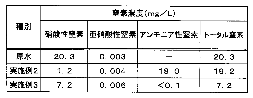
この結果から、次のように考察できる。実施例2では、硝酸性窒素が20.3mg/Lから1.2mg/Lに低下し、アンモニア性窒素が18.0mg/Lとなっており、硝酸性窒素がアンモニア性窒素に還元されていることが分かる。
一方、実施例3では、硝酸性窒素は7.2mg/Lに留まっているが、トータル窒素が20.3mg/Lから7.2mg/Lまで低下している。このトータル窒素濃度の差は、アンモニア性窒素が、陽イオン吸着剤であるゼオライトに吸着したことによると考えられる。この方法によって、トータル窒素濃度が低減できることが分かる。
このように、硫黄を含有する鉄粉と陽イオン交換能を有する吸着剤とを併用することによって、トータル窒素を効率的且つ簡便に低減することができることが分かる。
本発明方法は、硫黄を含有する鉄粉と汚染水を接触させることによって、汚染水中に含まれる窒素成分(硝酸性窒素および亜硝酸性窒素の一方または両方から選ばれる窒素成分)をアンモニア性窒素に還元し、アンモニア性窒素を含有する水からアンモニア性窒素を除去するものであり、窒素成分を除去して水を浄化する方法として最適である。
Claims (6)
- 硝酸性窒素および亜硝酸性窒素の一方または両方から選ばれる窒素成分に汚染された水を、硫黄を含有する鉄粉と接触させ、前記窒素成分をアンモニア性窒素に還元し、アンモニア性窒素を含有する水からアンモニア性窒素を除去することによって、水を浄化することを特徴とする汚染水の浄化方法。
- 鉄粉中の硫黄の含有量が0.3質量%以上、2.0質量%以下である請求項1に記載の汚染水の浄化方法。
- 鉄粉の平均粒径が1μm以上、10mm以下である請求項1または2に記載の汚染水の浄化方法。
- 汚染された水を、硫黄を含有する鉄粉と接触させる際に、水のpHを5~6に制御する請求項1または2に記載の汚染水の浄化方法。
- 汚染された水を、硫黄を含有する鉄粉と接触させる際に、外部の酸素を遮断する請求項1または2に記載の汚染水の浄化方法。
- 前記汚染された水を、前記鉄粉と接触させつつ、陽イオン交換能を有する吸着剤にも接触させ、前記窒素成分からアンモニア性窒素への還元と並行して、アンモニア性窒素の除去も行なう請求項1または2に記載の汚染水の浄化方法。
Applications Claiming Priority (4)
| Application Number | Priority Date | Filing Date | Title |
|---|---|---|---|
| JP2010-085533 | 2010-04-01 | ||
| JP2010085533 | 2010-04-01 | ||
| JP2010-210850 | 2010-09-21 | ||
| JP2010210850A JP5580704B2 (ja) | 2010-04-01 | 2010-09-21 | 汚染水の浄化方法 |
Publications (1)
| Publication Number | Publication Date |
|---|---|
| WO2011125398A1 true WO2011125398A1 (ja) | 2011-10-13 |
Family
ID=44762360
Family Applications (1)
| Application Number | Title | Priority Date | Filing Date |
|---|---|---|---|
| PCT/JP2011/054910 Ceased WO2011125398A1 (ja) | 2010-04-01 | 2011-03-03 | 汚染水の浄化方法 |
Country Status (2)
| Country | Link |
|---|---|
| JP (1) | JP5580704B2 (ja) |
| WO (1) | WO2011125398A1 (ja) |
Cited By (1)
| Publication number | Priority date | Publication date | Assignee | Title |
|---|---|---|---|---|
| CN111482185A (zh) * | 2019-01-29 | 2020-08-04 | 北京大学深圳研究生院 | 一种自支撑FeSx电催化剂及其制备方法与应用 |
Families Citing this family (1)
| Publication number | Priority date | Publication date | Assignee | Title |
|---|---|---|---|---|
| CN114149067B (zh) * | 2021-12-06 | 2023-12-26 | 纬地资源环境科技江苏有限公司 | 工业废水中无机氮的资源化固氮方法 |
Citations (12)
| Publication number | Priority date | Publication date | Assignee | Title |
|---|---|---|---|---|
| JPH038495A (ja) * | 1989-06-05 | 1991-01-16 | Kanatsu Giken Kogyo Kk | 脱窒・脱リン用組成物及び脱窒・脱リン方法 |
| JPH0747372A (ja) * | 1993-08-09 | 1995-02-21 | Meidensha Corp | 硝酸イオン廃水の処理方法 |
| JPH10244279A (ja) * | 1997-03-05 | 1998-09-14 | Nkk Corp | 鉄を用いた被処理水中の窒素およびリンの除去方法 |
| JPH10277567A (ja) * | 1997-04-04 | 1998-10-20 | Nkk Corp | 鉄を用いた排水処理方法 |
| JPH10309572A (ja) * | 1997-05-14 | 1998-11-24 | Nkk Corp | 水処理方法 |
| JP2000153283A (ja) * | 1998-11-20 | 2000-06-06 | Ngk Insulators Ltd | 窒素含有排水の処理方法 |
| JP2000271575A (ja) * | 1999-03-24 | 2000-10-03 | Kurita Water Ind Ltd | 硝酸性窒素含有水の処理方法 |
| JP2002210452A (ja) * | 2000-11-15 | 2002-07-30 | Kawasaki Steel Corp | 土壌、水および/またはガスの浄化方法ならびに有機ハロゲン化合物の脱ハロゲン用鉄粉 |
| JP2004292806A (ja) * | 2003-03-07 | 2004-10-21 | Nippon Steel Corp | 土壌修復剤および土壌修復方法 |
| JP2004331996A (ja) * | 2003-04-30 | 2004-11-25 | Jfe Steel Kk | 還元剤用海綿鉄、その製造方法およびその用途 |
| JP2005074363A (ja) * | 2003-09-02 | 2005-03-24 | Miura Co Ltd | 水処理剤および水処理方法 |
| JP2009082818A (ja) * | 2007-09-28 | 2009-04-23 | Kobe Steel Ltd | 重金属類を含有する汚染水の処理剤および処理方法 |
Family Cites Families (6)
| Publication number | Priority date | Publication date | Assignee | Title |
|---|---|---|---|---|
| DE3830850A1 (de) * | 1988-09-10 | 1990-03-22 | Gutec Gmbh | Verfahren zur entfernung des nitrit- und/oder nitratgehaltes in wasser |
| JPH10113678A (ja) * | 1996-10-14 | 1998-05-06 | Nisshin Steel Co Ltd | 硝酸イオン含有廃液の無害化処理方法及び装置 |
| JP3867562B2 (ja) * | 2000-11-30 | 2007-01-10 | Jfeスチール株式会社 | マグネタイト−鉄複合粉末混合物およびその製造方法、ならびに電波吸収体 |
| JP4706828B2 (ja) * | 2005-02-25 | 2011-06-22 | 三菱マテリアル株式会社 | 硝酸性窒素含有水の処理方法および処理装置 |
| JP4978222B2 (ja) * | 2007-02-07 | 2012-07-18 | 信越化学工業株式会社 | 硝酸性窒素を含む排水の処理方法 |
| JP5303263B2 (ja) * | 2008-12-25 | 2013-10-02 | クラリアント触媒株式会社 | 硝酸性窒素含有水処理用固体触媒および該触媒を用いた硝酸性窒素含有水の処理方法 |
-
2010
- 2010-09-21 JP JP2010210850A patent/JP5580704B2/ja active Active
-
2011
- 2011-03-03 WO PCT/JP2011/054910 patent/WO2011125398A1/ja not_active Ceased
Patent Citations (12)
| Publication number | Priority date | Publication date | Assignee | Title |
|---|---|---|---|---|
| JPH038495A (ja) * | 1989-06-05 | 1991-01-16 | Kanatsu Giken Kogyo Kk | 脱窒・脱リン用組成物及び脱窒・脱リン方法 |
| JPH0747372A (ja) * | 1993-08-09 | 1995-02-21 | Meidensha Corp | 硝酸イオン廃水の処理方法 |
| JPH10244279A (ja) * | 1997-03-05 | 1998-09-14 | Nkk Corp | 鉄を用いた被処理水中の窒素およびリンの除去方法 |
| JPH10277567A (ja) * | 1997-04-04 | 1998-10-20 | Nkk Corp | 鉄を用いた排水処理方法 |
| JPH10309572A (ja) * | 1997-05-14 | 1998-11-24 | Nkk Corp | 水処理方法 |
| JP2000153283A (ja) * | 1998-11-20 | 2000-06-06 | Ngk Insulators Ltd | 窒素含有排水の処理方法 |
| JP2000271575A (ja) * | 1999-03-24 | 2000-10-03 | Kurita Water Ind Ltd | 硝酸性窒素含有水の処理方法 |
| JP2002210452A (ja) * | 2000-11-15 | 2002-07-30 | Kawasaki Steel Corp | 土壌、水および/またはガスの浄化方法ならびに有機ハロゲン化合物の脱ハロゲン用鉄粉 |
| JP2004292806A (ja) * | 2003-03-07 | 2004-10-21 | Nippon Steel Corp | 土壌修復剤および土壌修復方法 |
| JP2004331996A (ja) * | 2003-04-30 | 2004-11-25 | Jfe Steel Kk | 還元剤用海綿鉄、その製造方法およびその用途 |
| JP2005074363A (ja) * | 2003-09-02 | 2005-03-24 | Miura Co Ltd | 水処理剤および水処理方法 |
| JP2009082818A (ja) * | 2007-09-28 | 2009-04-23 | Kobe Steel Ltd | 重金属類を含有する汚染水の処理剤および処理方法 |
Cited By (2)
| Publication number | Priority date | Publication date | Assignee | Title |
|---|---|---|---|---|
| CN111482185A (zh) * | 2019-01-29 | 2020-08-04 | 北京大学深圳研究生院 | 一种自支撑FeSx电催化剂及其制备方法与应用 |
| CN111482185B (zh) * | 2019-01-29 | 2023-06-20 | 北京大学深圳研究生院 | 一种自支撑FeSx电催化剂及其制备方法与应用 |
Also Published As
| Publication number | Publication date |
|---|---|
| JP2011224535A (ja) | 2011-11-10 |
| JP5580704B2 (ja) | 2014-08-27 |
Similar Documents
| Publication | Publication Date | Title |
|---|---|---|
| US11987512B2 (en) | Methods for treating selenocyanate in wastewater | |
| JP6118571B2 (ja) | 汚染土壌の処理方法 | |
| Chen et al. | Removal of ammonia nitrogen from wastewater using modified activated sludge | |
| JP2011240329A (ja) | 重金属類を含有する汚染水の処理剤および処理方法 | |
| US10059610B2 (en) | Reduction of the amount of sulphur compounds in a sulphur compounds contaminated wastewater stream using a granular sludge treatment system | |
| KR20130077739A (ko) | 유기물 함유수 처리 방법 | |
| JP2013123655A (ja) | シアン含有廃水の処理方法 | |
| Hamid et al. | A state-of-art review on the sustainable technologies for cadmium removal from wastewater | |
| Muhammad et al. | Coupled physicochemical and bacterial reduction mechanisms for passive remediation of sulfate-and metal-rich acid mine drainage | |
| Lee et al. | Removal of Mn (II) from aqueous solutions using manganese-coated sand samples | |
| EP3075711A1 (en) | System for decontamination of hazardous sulfur compounds in oilfield produced water | |
| Evangelho et al. | A trickling filter application for the treatment of a gold milling effluent | |
| CN116161834A (zh) | 一种基于零价铁填充床系统的重金属废水处理方法 | |
| JP5580704B2 (ja) | 汚染水の浄化方法 | |
| CN110950499A (zh) | 一种铜氨络合废水处理系统及工艺 | |
| US10301192B2 (en) | Removal of copper from aqueous streams using an iron promoted activated alumina | |
| Zaharia et al. | Versatile Zwitterionic Beads for Heavy Metal Ion Removal from Aqueous Media and Soils by Sorption and Catalysis Processes | |
| Viraraghavan et al. | Adsorption of mercury from wastewater by peat | |
| JP2015127049A (ja) | 汚染水または汚染土壌の処理剤および処理方法 | |
| CA2954480C (en) | Selenium and other contaminants removal process | |
| KR101164214B1 (ko) | 점토광물과 영가철 조합을 이용한 질산성질소 처리방법 | |
| KR20110109914A (ko) | 초산성 질소 함유수의 정화재 및 초산성 질소 함유수의 정화 방법 | |
| KR20040110352A (ko) | 마그네타이트 분말과 부영양화 물질 및 유기물 흡착제가함유된 미세구형 과립상태인 수처리 미세과립 제조방법 및초고속 수처리공정 | |
| JP2004216367A (ja) | 硝酸態及び亜硝酸態窒素含有化合物用処理材並びにそれを用いた土壌または水の処理方法 | |
| KR20040068831A (ko) | 마그네타이트 분말과 유기물 흡착제가 함유된 미세구형과립상태인 수처리 분말 및 처리공정 |
Legal Events
| Date | Code | Title | Description |
|---|---|---|---|
| 121 | Ep: the epo has been informed by wipo that ep was designated in this application |
Ref document number: 11765300 Country of ref document: EP Kind code of ref document: A1 |
|
| NENP | Non-entry into the national phase |
Ref country code: DE |
|
| 122 | Ep: pct application non-entry in european phase |
Ref document number: 11765300 Country of ref document: EP Kind code of ref document: A1 |