WO2011125154A1 - 燃料噴射弁及び燃料噴射装置 - Google Patents
燃料噴射弁及び燃料噴射装置 Download PDFInfo
- Publication number
- WO2011125154A1 WO2011125154A1 PCT/JP2010/056091 JP2010056091W WO2011125154A1 WO 2011125154 A1 WO2011125154 A1 WO 2011125154A1 JP 2010056091 W JP2010056091 W JP 2010056091W WO 2011125154 A1 WO2011125154 A1 WO 2011125154A1
- Authority
- WO
- WIPO (PCT)
- Prior art keywords
- fuel
- fuel injection
- ultrasonic transducer
- needle
- injection valve
- Prior art date
- Legal status (The legal status is an assumption and is not a legal conclusion. Google has not performed a legal analysis and makes no representation as to the accuracy of the status listed.)
- Ceased
Links
Images






Classifications
-
- F—MECHANICAL ENGINEERING; LIGHTING; HEATING; WEAPONS; BLASTING
- F02—COMBUSTION ENGINES; HOT-GAS OR COMBUSTION-PRODUCT ENGINE PLANTS
- F02M—SUPPLYING COMBUSTION ENGINES IN GENERAL WITH COMBUSTIBLE MIXTURES OR CONSTITUENTS THEREOF
- F02M61/00—Fuel-injectors not provided for in groups F02M39/00 - F02M57/00 or F02M67/00
- F02M61/04—Fuel-injectors not provided for in groups F02M39/00 - F02M57/00 or F02M67/00 having valves, e.g. having a plurality of valves in series
- F02M61/10—Other injectors with elongated valve bodies, i.e. of needle-valve type
- F02M61/12—Other injectors with elongated valve bodies, i.e. of needle-valve type characterised by the provision of guiding or centring means for valve bodies
-
- F—MECHANICAL ENGINEERING; LIGHTING; HEATING; WEAPONS; BLASTING
- F02—COMBUSTION ENGINES; HOT-GAS OR COMBUSTION-PRODUCT ENGINE PLANTS
- F02M—SUPPLYING COMBUSTION ENGINES IN GENERAL WITH COMBUSTIBLE MIXTURES OR CONSTITUENTS THEREOF
- F02M61/00—Fuel-injectors not provided for in groups F02M39/00 - F02M57/00 or F02M67/00
- F02M61/16—Details not provided for in, or of interest apart from, the apparatus of groups F02M61/02 - F02M61/14
-
- F—MECHANICAL ENGINEERING; LIGHTING; HEATING; WEAPONS; BLASTING
- F02—COMBUSTION ENGINES; HOT-GAS OR COMBUSTION-PRODUCT ENGINE PLANTS
- F02M—SUPPLYING COMBUSTION ENGINES IN GENERAL WITH COMBUSTIBLE MIXTURES OR CONSTITUENTS THEREOF
- F02M69/00—Low-pressure fuel-injection apparatus ; Apparatus with both continuous and intermittent injection; Apparatus injecting different types of fuel
- F02M69/04—Injectors peculiar thereto
- F02M69/041—Injectors peculiar thereto having vibrating means for atomizing the fuel, e.g. with sonic or ultrasonic vibrations
-
- F—MECHANICAL ENGINEERING; LIGHTING; HEATING; WEAPONS; BLASTING
- F02—COMBUSTION ENGINES; HOT-GAS OR COMBUSTION-PRODUCT ENGINE PLANTS
- F02M—SUPPLYING COMBUSTION ENGINES IN GENERAL WITH COMBUSTIBLE MIXTURES OR CONSTITUENTS THEREOF
- F02M69/00—Low-pressure fuel-injection apparatus ; Apparatus with both continuous and intermittent injection; Apparatus injecting different types of fuel
- F02M69/04—Injectors peculiar thereto
- F02M69/042—Positioning of injectors with respect to engine, e.g. in the air intake conduit
- F02M69/045—Positioning of injectors with respect to engine, e.g. in the air intake conduit for injecting into the combustion chamber
Definitions
- the present invention relates to a fuel injection valve and a fuel injection device.
- Patent Document 1 is disclosed as a means for realizing such a proposal.
- a disk-shaped ultrasonic transducer is integrally fixed and arranged on a plane portion surrounded by an opening / closing surface portion at a tip portion of a needle, and is provided so as to face the reflecting member.
- a fuel injection valve comprising: Such a fuel injection valve easily generates cavitation bubbles by ultrasonic waves between the surface of the ultrasonic transducer and the plane of the reflecting member.
- the direction of vibration imparted to the fuel by the ultrasonic vibrator is the same as the fuel flow direction. For this reason, there exists a period when the fine bubbles are included and a period when the fine bubbles are not included, and there is a possibility that the fine bubbles cannot be uniformly distributed.
- the ultrasonic transducer is disposed on the flat surface surrounded by the opening / closing surface at the tip of the needle, it is very difficult to mix fine bubbles into the entire amount of fuel injected from the injection hole. .
- an object of the present invention is to uniformly mix fine bubbles into the injected fuel.
- a fuel injection valve disclosed in this specification includes a nozzle body provided with a seat portion, and is slidably disposed in the nozzle body, and is seated on the seat portion to thereby inject fuel.
- a part of the fuel flow path between the needle body and the outer peripheral wall of the needle disposed in a cylindrical shape between the nozzle body and the needle on the upstream side of the seat portion,
- an ultrasonic transducer that expands and contracts to change the flow passage area of the fuel flow passage.
- the ultrasonic transducer can be expanded and contracted to enlarge and / or reduce the flow path area.
- the ultrasonic vibrator By providing the ultrasonic vibrator on the upstream side of the seat portion, it is possible to keep the state where fine bubbles are mixed in the fuel injected from the nozzle hole provided downstream of the seat portion. Further, by changing the flow path area of the fuel flow path by expansion and contraction of the ultrasonic vibrator, ultrasonic vibration can be applied to the entire amount of fuel to be injected. As a result, fine bubbles can be mixed uniformly in the injected fuel. The fuel in which fine bubbles are uniformly mixed is sequentially injected from the fuel injection holes.
- the fine bubbles maintained in the fuel injection valve are crushed after the injection, thereby atomizing the fuel.
- the annular volume of the fuel flow path defined by the length of the ultrasonic transducer with respect to the needle axis and the flow path area is the time until the needle is separated from the seat portion and then seated on the seat portion again. It is desirable that the fuel amount be set to be equal to or greater than the maximum amount of fuel injected by one injection.
- the annular volume is defined as described above when no drive signal is input to the ultrasonic transducer and the ultrasonic transducer is stationary. By setting the annular volume in this way, it is possible to inject fuel in which fine bubbles are uniformly mixed regardless of the amount of fuel injected at one time.
- the fuel injection valve as described above may be provided with swirl flow imparting means for imparting a swirl flow to the fuel flow flowing into the region where the ultrasonic transducer is disposed upstream of the ultrasonic transducer.
- swirl flow imparting means for imparting a swirl flow to the fuel flow flowing into the region where the ultrasonic transducer is disposed upstream of the ultrasonic transducer.
- Such a swirl flow applying means may be, for example, a mixed flow groove provided on the outer peripheral wall of the needle and / or the inner peripheral wall of the nozzle body. Moreover, it can be set as the mixed flow groove
- the distance between the inner surface of the ultrasonic transducer and the outer peripheral surface of the needle is such that n is a natural number and ⁇ is the wavelength of the ultrasonic wave emitted by the ultrasonic transducer. , (N ⁇ 1/4) ⁇ ⁇ .
- the fuel injection device disclosed in the present specification includes a nozzle body including a seat portion, a needle that is slidably disposed in the nozzle body, and stops the fuel injection by being seated on the seat portion, On the upstream side of the seat portion, a fuel flow path is formed between the nozzle body and the needle to form a fuel flow path between the outer peripheral wall of the needle and the flow path area of the fuel flow path is changed.
- An ultrasonic transducer that expands and contracts, and a control unit that drives the ultrasonic transducer together with the opening of the needle.
- the control unit can drive the ultrasonic transducer in a direction in which the flow passage area of the fuel flow channel is enlarged at the start of driving of the ultrasonic transducer.
- the flow path area of the fuel flow path is enlarged and the volume of the area surrounded by the ultrasonic transducer is increased, the pressure in the area is reduced, and fine bubbles are generated by cavitation.
- control unit can apply a voltage that has been half-wave rectified so that the ultrasonic vibrator oscillates in a direction that enlarges the flow passage area of the fuel flow passage.
- the fine bubbles are generated when the volume of the region surrounded by the ultrasonic transducer is increased and the pressure in the region is reduced. For this reason, it is possible to continuously generate fine bubbles by driving the ultrasonic vibrator with the half-wave rectified voltage.
- fine bubbles can be mixed uniformly into the injected fuel.
- FIG. 1 is a diagram illustrating a configuration example of an engine system according to an embodiment.
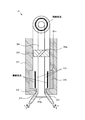
- FIG. 2 is a diagram showing a configuration example of the fuel injection valve of the embodiment.
- 3 is a cross-sectional view of the fuel injection valve of the embodiment taken along line AA in FIG.
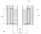
- FIG. 4 is an explanatory view of the annular volume in the fuel injection valve.
- FIG. 5A is an explanatory view showing an example in which a mixed flow groove is provided in the needle.
- FIG. 5B is an explanatory view showing an example in which a diagonal flow groove is provided in the nozzle body.
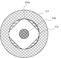
- FIG. 6 is an explanatory view showing another shape of the eccentricity suppressing portion.
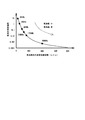
- FIG. 7 shows the correlation between the bubble generation frequency and the bubble diameter.
- FIG. 8 shows the correlation between the bubble generation frequency and the relative strength of the bubbles.
- FIG. 9 shows the correlation between the bubble diameter and the bubble collapse time.
- FIG. 10 shows the observation of destruction of bubbles in the aqueous solution.
- FIG. 1 is a diagram showing a configuration example of an engine system 1 equipped with a fuel injection control device of the present invention.
- FIG. 1 shows only a part of the configuration of the engine.
- the engine system 1 shown in FIG. 1 includes an engine 100 that is a power source, and includes an engine ECU (Electronic Control Unit) 10 that comprehensively controls the operation of the engine 100.
- the engine system 1 also includes a fuel injection valve 21 that injects fuel into the combustion chamber 11 of the engine 100 and an ultrasonic drive device 22 that drives the ultrasonic transducer 218 in the fuel injection valve 21.
- the engine ECU 10 has a function of a control unit.
- the fuel injection valve 21 and the ultrasonic drive device 22 provided with the engine ECU 10 and the ultrasonic transducer 218 are included in the fuel injection device.
- the engine ECU 10 includes a CPU (Central Processing Unit) that performs arithmetic processing, a ROM (Read Only Memory) that stores programs, a RAM (Random Access Memory) and NVRAM (Non Volatile RAM) that store data and the like. Computer.
- CPU Central Processing Unit
- ROM Read Only Memory
- RAM Random Access Memory
- NVRAM Non Volatile RAM
- the engine 100 is an engine mounted on a vehicle and includes a piston 12 that constitutes a combustion chamber 11. Piston 12 is slidably fitted to a cylinder of engine 100. And the piston 12 is connected with the crankshaft which is an output shaft member via the connecting rod.
- the intake air flowing into the combustion chamber 11 from the intake port 13 is compressed in the combustion chamber 11 by the upward movement of the piston 12.
- the engine ECU 10 determines the fuel injection timing based on the position of the piston 12 from the crank angle sensor and the information of the cam shaft rotation phase from the intake cam angle sensor, and sends a signal to the fuel injection valve 21.
- the fuel injection valve 21 injects fuel at an instructed injection timing in accordance with a signal from the engine ECU 10.
- the fuel injected from the fuel injection valve 21 is mixed with the intake air compressed by atomization. Then, the fuel mixed with the intake air is burned by being ignited by the spark plug 18, expands in the combustion chamber 11, and lowers the piston 12.
- the descending motion is changed to the shaft rotation of the crankshaft through the connecting rod, whereby the engine 100 obtains power.
- an intake port 13 that communicates with the combustion chamber 11 and an intake passage 14 that is connected to the intake port 13 and guides intake air from the intake port 13 to the combustion chamber 11.
- an exhaust port 15 communicating with the combustion chamber 11 and an exhaust passage 16 for guiding exhaust gas generated in the combustion chamber to the outside of the engine 100 are connected to the combustion chamber 11 of each cylinder.
- an air flow meter, a throttle valve 17, and a throttle position sensor are installed in the intake passage 14.
- the air flow meter and the throttle position sensor detect the amount of intake air passing through the intake passage 14 and the opening of the throttle valve 17, respectively, and transmit the detection results to the engine ECU 10.
- the engine ECU 10 recognizes the intake air amount introduced into the intake port 13 and the combustion chamber 11 based on the transmitted detection result, and adjusts the intake air amount by adjusting the opening of the throttle valve 17.
- the throttle valve 17 preferably employs a throttle-by-wire system using a step motor.
- the opening of the throttle valve 17 is changed in conjunction with an accelerator pedal (not shown) via a wire instead of a step motor.
- a mechanical throttle mechanism as described above can also be applied.
- a turbocharger 19 is installed in the exhaust passage 16.
- the turbocharger 19 uses the kinetic energy of the exhaust gas flowing through the exhaust passage 16 to rotate the turbine, compresses the intake air that has passed through the air cleaner, and sends it to the intercooler.
- the compressed intake air is cooled by the intercooler and then introduced into the intake passage 14.
- the engine 100 is not limited to a supercharged engine provided with the turbocharger 19, and may be a natural aspiration engine.
- the piston 12 has a cavity on its top surface.
- the wall surface of the cavity is formed by a gentle curved surface continuous from the direction of the fuel injection valve 21 to the direction of the ignition plug 18, and the fuel injected from the fuel injection valve 21 is near the ignition plug 18 along the wall surface shape. Lead to.
- the piston 12 can form a cavity at an arbitrary position and shape according to the specifications of the engine 100, such as a reentrant combustion chamber in which a cavity is formed in an annular shape in the central portion of the top surface.
- the fuel injection valve 21 is attached to the combustion chamber 11 below the intake port 13 in an oblique direction. Based on an instruction from the engine ECU 10, the fuel injection valve 21 receives a fuel supplied from a fuel pump through a fuel flow path through a fuel flow path through a fuel injection hole 212 provided at equal intervals in the circumferential direction of the tip of the nozzle body 211. 11 is injected directly. The injected fuel is atomized in the combustion chamber 11 and mixed with the intake air, and is guided to the vicinity of the spark plug 18 along the shape of the cavity. The leaked fuel from the fuel injection valve 21 is returned from the relief valve to the fuel tank through the relief pipe.
- the fuel injection valve 21 is not limited to the lower portion of the intake port 13 and can be installed at an arbitrary position in the combustion chamber 11. Further, the fuel injection valve 21 is not limited to the combustion chamber 11 and may be provided in the intake port 13, or may be provided in both the combustion chamber 11 and the intake port 13.
- the engine 100 is not limited to a gasoline engine using gasoline as a fuel, but may be any of a diesel engine using light oil as a fuel and a flexible fuel engine using a fuel in which gasoline and alcohol are mixed at an arbitrary ratio.
- the engine system 1 may be a hybrid system that combines the engine 100 and a plurality of electric motors.
- FIG. 2 is a configuration diagram showing a schematic configuration of the fuel injection valve 21 of the embodiment.
- 3 is a cross-sectional view taken along line AA in FIG.
- FIG. 2 shows only the configuration of the tip portion of the fuel injection valve 21.
- the fuel injection valve 21 includes a nozzle body 211 and a needle 214 that is slidably disposed in the nozzle body 211.
- the fuel injection valve 21 is an outer valve that is opened when the needle 214 moves toward the outside of the nozzle body 211.
- the nozzle body 211 has a fuel injection hole 212 at the tip.
- a seat portion 217 is located on the inner peripheral surface of the fuel injection hole 212.
- a cap-shaped portion 214 a is provided at the tip of the needle 214.
- the needle 214 stops fuel injection when the cap-shaped portion 214 a is seated on the seat portion 217.
- the needle 214 is not limited to the outer valve having the cap-shaped portion 214a, but may be a needle-shaped inner valve having a sharp tip.
- the nozzle body 211 protrudes into the combustion chamber 11 of the engine 100.
- the high-pressure fuel pumped from the fuel pump and accumulated in the fuel flow path 213 inside the nozzle body 211 is injected into the engine cylinder from the fuel injection hole 212 in accordance with an instruction from the engine ECU 10.
- the fuel injection valve 21 includes an ultrasonic vibrator 218 on the upstream side of the seat portion 217.
- the ultrasonic transducer 218 is arranged in a cylindrical shape between the nozzle body 211 and the needle 214 as shown in FIGS. As a result, the ultrasonic transducer 218 forms a part of the fuel flow path 213 between the outer peripheral wall of the needle 214.
- the ultrasonic transducer 218 is arranged in a cylindrical shape and expands and contracts so as to change the flow path area S. More specifically, the ultrasonic transducer 218 expands and contracts so as to enlarge and reduce the flow path area S of the fuel flow path 213.
- the flow area S of the fuel flow path 213 includes a cylindrical cross-sectional area having a diameter Dpz on which the ultrasonic transducer 218 is disposed and a cross-sectional area of the needle 214 having an outer diameter Dn. And the difference.
- the annular volume V of the fuel flow path 213 as shown in FIG. 4 defined by the length Lpz of the ultrasonic transducer 218 with respect to the needle axis and the flow path area S is the flow path area shown in FIG. It is calculated by multiplying S by the length Lpz of the ultrasonic transducer 218.
- Such an annular volume V is injected by one injection of the fuel injection valve 21 in a state where the drive signal to the ultrasonic vibrator 218 is not input and the ultrasonic vibrator 218 is stationary.
- the maximum fuel amount Qf is set.
- one injection is fuel injection performed during a period until the needle 214 is separated from the seat portion 217 and then seated on the seat portion 217 again.
- the thickness dimension of the ultrasonic transducer 218 will be described.
- the fuel before injection is accumulated in the fuel flow path 213 at a high pressure (for example, 1 MPa).
- a high pressure for example, 1 MPa.
- the ultrasonic vibrator 218 is required to have a sufficient thickness dimension so that an appropriate volume change amount for obtaining the pressure in the fuel flow path 213 below the vapor pressure of the fuel can be obtained.
- An appropriate thickness dimension of the ultrasonic transducer 218 can be obtained by the following equations (3) to (5).
- the needle 214 is provided with an eccentricity suppressing portion 215 that is orthogonal to the axis of the needle 214.
- the eccentricity suppressing part 215 is provided integrally with the needle 214.
- the eccentricity suppressing portion 215 is in sliding contact with the inner peripheral surface of the nozzle body 211 and serves as a guide for the needle 214 to suppress the eccentricity of the needle 214.
- a mixed flow groove 215 a is provided on the outer peripheral surface of the eccentricity suppressing portion 215.
- the eccentricity suppressing unit 215 is located upstream of the ultrasonic transducer 218 and imparts a swirl flow to the fuel flow flowing into the region where the ultrasonic transducer 218 is disposed.
- the region where the ultrasonic transducer 218 is disposed is an annular volume V.
- the mixed flow groove 215a can suppress the collapse of the fine bubbles in the fuel injection valve by giving a swirl flow to the fuel flow flowing into the region where the ultrasonic vibrator 218 is disposed.
- the eccentricity suppressing part 215 and the mixed flow groove 215a are not limited to one and may be provided in plural. Further, instead of the mixed flow groove 215a, the mixed flow groove 215a and the mixed flow groove 214b provided on the outer peripheral wall of the needle 214 as shown in FIG. 5A or as shown in FIG. 5B. A mixed flow groove 211a provided on the inner peripheral wall of the nozzle body 211 can also be employed. As described above, when the mixed flow groove 214b and the mixed flow groove 211a are provided, or when the mixed flow groove itself is not provided, an eccentricity suppressing portion 216 as shown in FIG. 6 can be employed.
- the eccentricity suppression unit 216 includes sliding contact portions 216a that are in sliding contact with the inner peripheral surface of the nozzle body 211 at several locations. And a fuel can be distribute
- the mixed flow groove 215a is inclined at a predetermined angle ⁇ with respect to the needle 214 axis.
- the inclination angle ⁇ of the mixed flow groove 215a will be described.
- the relationship between the inclination angle ⁇ of the mixed flow groove 215a and the fuel swirl frequency can be expressed by the following equation.
- Swivel frequency (Injection rate ⁇ Diagonal groove area ratio / Diagonal groove area ⁇ COS ( ⁇ / 180 ⁇ )) / Dpz / 2 ⁇ (6) ( ⁇ : Angle of mixed flow groove, Dpz: Inner diameter of ultrasonic transducer)
- ⁇ Angle of mixed flow groove, Dpz: Inner diameter of ultrasonic transducer
- the ultrasonic vibration provided by the ultrasonic vibrator 218 transmits the fuel in the fuel flow path 213 and reaches the needle 214, and a part thereof becomes a reflected wave and proceeds in the direction of the ultrasonic vibrator 218.
- the ultrasonic transducer 218 and the needle 214 are coaxial, the distance between them is (n ⁇ 1/4) ⁇ (n is a natural number) with respect to the ultrasonic wavelength ⁇ , so that the ultrasonic transducer 218 is obtained.
- the sparse and dense peaks of the vibration wave applied by and the reflected wave reflected by the needle 214 overlap.
- the ultrasonic vibrator 218 is provided in a cylindrical shape on the wall surface of the fuel flow path 213 near the fuel injection hole 212.
- the ultrasonic vibrator 218 is a piezoelectric element whose volume expands or contracts when a voltage is applied by energization from the ultrasonic driving device 22.
- the ultrasonic vibrator 218 expands in volume when a positive voltage is applied, decreases the volume of the fuel flow path 213 (annular volume V), and returns to its original volume when the application of the positive voltage is completed. Return the annular volume V to its original position.
- the ultrasonic transducer 218 contracts in volume when a negative voltage is applied, and increases the capacity of the fuel flow path 213 (annular volume V). Returning, the capacity of the fuel flow path 213 is restored.
- the ultrasonic vibrator 218 repeatedly expands and contracts by applying a voltage continuously, and increases or decreases the volume of the fuel flow path 213 in synchronization with the frequency of the AC voltage.
- the annular volume V contracts, the fuel pressure in the annular volume V decreases and fine bubbles are generated by cavitation.
- the volume of the ultrasonic vibrator 218 may be expanded when a negative voltage is applied, and the volume may be contracted when a positive voltage is applied.
- Such an ultrasonic transducer 218 is an example of the configuration of the ultrasonic vibration applying means of the present invention.
- the ultrasonic drive device 22 is a drive unit that energizes the ultrasonic vibrator 218 inside the fuel injection valve 21.
- the ultrasonic drive device 22 expands and contracts the volume of the ultrasonic vibrator 218 by applying an AC voltage to the ultrasonic vibrator 218 based on an instruction from the engine ECU 10.
- the driving of the ultrasonic vibrator 218 is performed when fuel injection is started. In other words, the ultrasonic transducer 218 is not driven when the valve is closed. If fine bubbles are generated in the fuel injection valve 21 when the valve is closed and the fine bubbles are crushed inside the fuel injection valve 21, there is a risk of damage in the fuel injection valve 21 due to erosion. In order to avoid this, the ultrasonic vibrator 218 is performed when the fuel injection valve 21 is in the open state.
- the ultrasonic transducer 218 is driven in the direction in which the flow channel area of the fuel flow channel 213 is enlarged at the start of driving of the ultrasonic transducer 218. That is, first, the flow channel area of the fuel flow channel 213 is expanded, and the annular volume V in the region surrounded by the ultrasonic transducer 218 is expanded. As a result, the pressure in the region decreases, and fine bubbles are generated by cavitation. By immediately expanding the flow path area at the start of driving, it is possible to quickly generate fine bubbles and prepare for fuel injection.
- “at the start of driving” includes not only the same time as the start of fuel injection by the fuel injection valve 21 but also a minute time before and after that. Therefore, the engine ECU 10 may start the application of the first ultrasonic vibration within a minute time before and after the start of fuel injection by the fuel injection valve 21 without being limited thereto.
- the engine ECU 10 applies a voltage half-wave rectified to the ultrasonic vibrator 218 so that the ultrasonic vibrator 218 vibrates in the direction of expanding the flow path area S of the fuel flow path 213.
- the fine bubbles are generated when the volume (annular volume V) of the region where the ultrasonic transducer is arranged around increases, the pressure in the region decreases. For this reason, it is possible to continuously generate fine bubbles by driving the ultrasonic vibrator with the half-wave rectified voltage.
- the bubble piece since the size of the bubble piece is greatly different from the resonance diameter of the ultrasonic wave, only a slight expansion or contraction occurs in the bubble piece. However, the bubble piece gradually grows by applying ultrasonic waves continuously by the Rectified Diffusion due to the following two effects.
- the fine bubble pieces in the liquid gradually grow by the rectified diffusion of the above two effects, but the growth is very slight in one cycle of the ultrasonic wave. Therefore, by maintaining the application of ultrasonic waves to some extent, bubbles due to cavitation can be grown to the ultrasonic resonance diameter.
- the generation of fine bubbles in the liquid is promoted when the liquid pressure becomes equal to or lower than the vapor pressure of the liquid. Therefore, when the first ultrasonic vibration is applied, the engine ECU 10 vibrates the ultrasonic vibrator 218 in a direction in which the volume of the fuel flow path 213 increases, thereby adjusting the fuel pressure in the fuel flow path 213 to the fuel. It is possible to generate fine bubbles efficiently with a vapor pressure of less than or equal to the above. In this case, when applying the first ultrasonic vibration, the engine ECU 10 can also apply an alternating voltage to the ultrasonic vibrator 218 to vibrate in the direction in which the volume of the fuel flow path 213 increases and decreases. .
- the engine ECU 10 when applying the first ultrasonic vibration, applies a voltage half-wave rectified to a positive voltage to the ultrasonic vibrator 218 to vibrate in the direction in which the volume of the fuel flow path 213 decreases. It can also be made. However, in any control, since the fuel pressure in the fuel flow path 213 is increased, it is not possible to obtain the generation efficiency of the fine bubbles as high as the above control.
- the application of the first ultrasonic vibration preferably has a frequency of 50 kHz or more, and for example, the frequency can be 1 MHz.
- the predetermined period for applying the ultrasonic vibration is preferably set to an appropriate period so that the ultrasonic vibration does not reach the resonance diameter of the fine bubbles. For example, several periods (4 to 10) from the start of fuel injection. Period) pulse wave.
- FIG. 10 shows observation of the bursting of bubbles in the aqueous solution.
- the bubbles in the aqueous solution are destroyed by the self-pressurization effect due to the surface tension over time, the bubble internal pressure and the charge amount at the gas-liquid interface increase, and the bubble diameter shrinkage.
- the bubble liquid film is pulverized by the energy that releases the internal pressure of the bubble and the charge amount at the gas-liquid interface at once, and the droplet is made ultrafine (see the lower part of FIG. 10). In this case, even when the bubbles are forcibly crushed by an external stimulus (trigger), the droplets are made ultrafine by the same mechanism.
- the droplets are made ultrafine by the crushing energy of the fine bubbles in the liquid. Therefore, atomization of the injected fuel of the internal combustion engine can be promoted by utilizing the crushing energy of the fine bubbles in the fuel.
Landscapes
- Engineering & Computer Science (AREA)
- Chemical & Material Sciences (AREA)
- Combustion & Propulsion (AREA)
- Mechanical Engineering (AREA)
- General Engineering & Computer Science (AREA)
- Fuel-Injection Apparatus (AREA)
Abstract
燃料噴射弁21は、燃料噴射弁シート部217を備えたノズルボディ211と、このノズルボディ211内に摺動自在に配置され、シート部217に着座することによって、燃料の噴射を停止するニードル214を備える。また、燃料噴射弁21は、シート部217の上流側において、ノズルボディ211とニードル214との間に筒状に配置されてニードル214の外周壁との間に燃料流路213の一部を形成するとともに、燃料流路213の流路面積Sを拡大及び/又は縮小するように伸縮する超音波振動子218を備えている。
Description
本発明は燃料噴射弁及び燃料噴射装置に関する。
内燃機関の燃費や排気エミッションを改善するために、噴射燃料の噴霧粒径を微細化して燃焼性を向上させることが要求されている。噴霧粒径を微細化する手段の一つとして、従来、噴射前の燃料に所定の超音波振動を付与する手法が知られている。
近年では、超音波振動の付与による噴霧粒径の微細化の新たな手法も提案されている。例えば、高周波の超音波振動によって燃料中にキャビテーションによる微細気泡を発生させ、噴射後に微細気泡が圧壊するときのエネルギーによって噴霧粒径を微細化する提案がされている。この提案によれば、燃料に付与する超音波振動の周波数が高いほどより微細な気泡が多量に発生し、より大きな気泡の圧壊エネルギーを得られることから、従来手法よりも噴霧粒径を微細化することが可能である。
このような提案を具現化するものとして、例えば、特許文献1が開示されている。特許文献1には、ニードルの先端部における開閉面部に囲まれた平面部に、円板状の超音波振動子を一体的に固着して配置し、これに対向するように設けられた反射部材を備えた燃料噴射弁が開示されている。このような燃料噴射弁は、超音波振動子の表面と反射部材の平面との間で超音波によりキャビテーションの気泡を容易に発生させる。
しかしながら、前記のような燃料噴射弁は、超音波振動子によって燃料に付与される振動の方向は燃料の流れ方向と同一方向となる。このため、微細気泡が含まれる時期と微細気泡が含まれない時期とが存在し、微細気泡を均一に分布させることができないおそれがある。また、超音波振動子が、ニードルの先端部における開閉面部に囲まれた平面部に配置されているため、噴孔から噴射される燃料の全量に微細気泡を混入させることは非常に困難である。
そこで本発明は、噴射される燃料に均一に微細気泡を混入させることを課題とする。
上記課題を解決するために本明細書開示の燃料噴射弁は、シート部を備えたノズルボディと、前記ノズルボディ内に摺動自在に配置され、前記シート部に着座することによって、燃料の噴射を停止するニードルと、前記シート部の上流側において、前記ノズルボディと前記ニードルとの間に筒状に配置されて前記ニードルの外周壁との間に燃料流路の一部を形成するとともに、前記燃料流路の流路面積を変化させるように伸縮する超音波振動子と、を備えたことを特徴する。ここで、前記超音波振動子は、前記流路面積を拡大及び/又は縮小するように伸縮することができる。
シート部よりも上流側に超音波振動子を備えることによって、シート部よりも下流に設けられる噴孔から噴射される燃料に微細気泡を混入した状態としておくことができる。また、超音波振動子の伸縮により燃料流路の流路面積を変化させることにより、噴射される燃料の全量に対して超音波振動を付与することができる。これにより噴射される燃料に均一に微細気泡を混入させることができる。均一に微細気泡が混入した燃料は、順次燃料噴射孔から噴射される。
燃料噴射弁内で維持された微細気泡が、噴射後に圧壊することによって燃料の微粒化が図られる。
この結果、着火遅れ期間の短縮、燃焼速度の増加、燃料によるオイル希釈の抑制、デポジット堆積の抑制、ノッキング発生の抑制を高い次元でバランスよく実現することができる。
前記超音波振動子のニードル軸線に対する長さと、流路面積とで規定される前記燃料流路の環状容積は、前記ニードルが前記シート部から離座し、その後、再びシート部に着座するまでの一回の噴射によって噴射される燃料量の最大量以上に設定されていることが望ましい。ここで、前記環状容積は、前記超音波振動子への駆動信号が入力されておらず、前記超音波振動子が静止した状態において、前記のように規定される。環状容積をこのように設定しておくことにより、一回に噴射される燃料量がどのような場合であっても均一に微細気泡が混入した燃料を噴射することができる。
前記のような燃料噴射弁は、前記超音波振動子よりも上流側に、前記超音波振動子が配置された領域に流れ込む燃料流れに旋回流を付与する旋回流付与手段を備えることができる。旋回流付与手段を備えることにより、超音波振動子が配置された領域に流れ込む燃料流れが旋回整流される。これにより、燃料噴射弁内での微細気泡の圧壊を抑制することができる。
このような旋回流付与手段は、例えば、前記ニードルの外周壁及び/又は前記ノズルボディの内周壁に設けられた斜流溝とすることができる。また、前記ニードルに一体に設けられ、前記ノズルボディの内周面に摺接する偏心抑制部の外周面に設けられた斜流溝とすることができる。
前記のような燃料噴射弁において、前記超音波振動子の内側表面と前記ニードルの外周面との距離は、nを自然数とし、λを前記超音波振動子が発する超音波の波長としたときに、(n±1/4)×λに設定することができる。このような波長とすることにより、超音波振動子から発振された振動がニードルの外周面において反射され、この反射波が振動を増幅させる。この結果、効率よく微細気泡を発生させることができる。
本明細書開示の燃料噴射装置は、シート部を備えたノズルボディと、前記ノズルボディ内に摺動自在に配置され、前記シート部に着座することによって、燃料の噴射を停止するニードルと、前記シート部の上流側において、前記ノズルボディと前記ニードルとの間に筒状に配置されて前記ニードルの外周壁との間に燃料流路を形成するとともに、前記燃料流路の流路面積を変化させるように伸縮する超音波振動子と、前記ニードルの開弁とともに前記超音波振動子を駆動する制御部と、を備えたことを特徴する。
前記制御部は、前記超音波振動子の駆動開始時に前記燃料流路の流路面積を拡大する方向に前記超音波振動子を駆動することができる。燃料流路の流路面積が拡大され、超音波振動子で囲まれた領域の容積が拡大するとその領域の圧力が低下し、キャビテーションによる微細気泡が発生する。駆動開始時に即座に流路面積を拡大することによって、迅速に微細気泡を発生させ、燃料噴射に備えることができる。
また、前記制御部は、前記超音波振動子が前記燃料流路の流路面積を拡大する方向に振動するように半波整流した電圧を前記超音波振動子に印加することができる。微細気泡は、超音波振動子で囲まれた領域の容積が拡大するとその領域の圧力が低下することによって発生する。このため、半波整流した電圧によって超音波振動子を駆動することによって連続的に微細気泡を発生させることができる。
本明細書に開示された燃料噴射弁及び燃料噴射装置によれば、噴射される燃料に均一に微細気泡を混入させることができる。
以下、本発明を実施するための形態を図面と共に詳細に説明する。
本発明の実施例について図面を参照しつつ説明する。図1は、本発明の燃料噴射制御装置を搭載したエンジンシステム1の一構成例を示した図である。なお、図1にはエンジンの一部の構成のみを示している。
図1に示すエンジンシステム1は、動力源であるエンジン100を備えており、エンジン100の運転動作を総括的に制御するエンジンECU(Electronic Control Unit)10を備えている。また、エンジンシステム1は、エンジン100の燃焼室11内へ燃料を噴射する燃料噴射弁21と、燃料噴射弁21内の超音波振動子218を駆動させる超音波駆動装置22とを備えている。エンジンECU10は、制御部の機能を備える。エンジンECU10、超音波振動子218を備えた燃料噴射弁21及び超音波駆動装置22は、燃料噴射装置に含まれる。エンジンECU10は、演算処理を行うCPU(Central Processing Unit)と、プログラム等を記憶するROM(Read Only Memory)と、データ等を記憶するRAM(Random Access Memory)やNVRAM(Non Volatile RAM)と、を備えるコンピュータである。
エンジン100は、車両に搭載されるエンジンであって、燃焼室11を構成するピストン12を備えている。ピストン12は、エンジン100のシリンダに摺動自在に嵌合されている。そして、ピストン12は、コネクティングロッドを介して出力軸部材であるクランクシャフトに連結されている。
吸気ポート13から燃焼室11内へ流入した吸入空気は、ピストン12の上昇運動により燃焼室11内で圧縮される。エンジンECU10は、クランク角センサからのピストン12の位置、および吸気カム角センサからのカム軸回転位相の情報に基づき、燃料噴射タイミングを決定し燃料噴射弁21に信号を送る。燃料噴射弁21は、エンジンECU10の信号に従って、指示された噴射タイミングで燃料を噴射する。燃料噴射弁21より噴射された燃料は、霧化して圧縮された吸入空気と混合される。そして、吸入空気と混合された燃料は、点火プラグ18によって点火されることで燃焼し、燃焼室11内を膨張させてピストン12を下降させる。この下降運動がコネクティングロッドを介してクランクシャフトの軸回転に変更されることにより、エンジン100は動力を得る。
燃焼室11には、それぞれ燃焼室11と連通する吸気ポート13と、吸気ポート13に連結し、吸入空気を吸気ポート13から燃焼室11へと導く吸気通路14とが接続されている。更に、各気筒の燃焼室11には、それぞれ燃焼室11と連通する排気ポート15と、燃焼室で発生した排気ガスをエンジン100の外部へと導く排気通路16が接続されている。
吸気通路14には、エアフロメータ、スロットルバルブ17およびスロットルポジションセンサが設置されている。エアフロメータおよびスロットルポジションセンサは、それぞれ吸気通路14を通過する吸入空気量、スロットルバルブ17の開度を検出し、検出結果をエンジンECU10に送信する。エンジンECU10は、送信された検出結果に基づいて吸気ポート13および燃焼室11へ導入される吸入空気量を認識し、スロットルバルブ17の開度を調整することで吸入空気量を調節する。
スロットルバルブ17は、ステップモータを用いたスロットルバイワイヤ方式を適用することが好ましいが、例えばステップモータの代わりにワイヤなどを介してアクセルペダル(図示しない)と連動し、スロットルバルブ17の開度が変更されるような機械式スロットル機構を適用することもできる。
排気通路16には、ターボチャージャ19が設置されている。ターボチャージャ19は、排気通路16を流通する排気ガスの運動エネルギーを利用してタービンを回転させ、エアクリーナーを通過した吸入空気を圧縮してインタークーラーへと送り込む。圧縮された吸入空気は、インタークーラーで冷却された後に吸気通路14へと導入される。この場合、エンジン100は、ターボチャージャ19を備える過給機付エンジンに限られず、自然吸気(Natural Aspiration)エンジンであってもよい。
ピストン12は、その頂面にキャビティを有する。キャビティは、燃料噴射弁21の方向から点火プラグ18の方向へと連続するなだらかな曲面によってその壁面が形成されており、燃料噴射弁21から噴射された燃料を壁面形状に沿って点火プラグ18近傍へと導く。この場合、ピストン12は、その頂面の中央部分に円環状にキャビティが形成されるリエントラント型燃焼室等、エンジン100の仕様に応じて任意の位置・形状でキャビティを形成することができる。
燃料噴射弁21は、吸気ポート13下部の燃焼室11に斜め方向に装着されている。燃料噴射弁21は、エンジンECU10の指示に基づいて、フューエルポンプから燃料流路を通じて高圧供給された燃料をノズルボディ211先端部の円周方向に等間隔で設けられた燃料噴射孔212より燃焼室11内へ直接噴射する。噴射された燃料は、燃焼室11内で霧化し吸入空気と混合されつつキャビティの形状に沿って点火プラグ18近傍へと導かれる。燃料噴射弁21のリーク燃料は、リリーフ弁からリリーフ配管を通じて燃料タンクへと戻される。
この場合、燃料噴射弁21は、吸気ポート13下部に限られず燃焼室11の任意の位置に設置することができる。更に、燃料噴射弁21は、燃焼室11に限られず吸気ポート13に設けてもよいし、燃焼室11と吸気ポート13との両方に設けてもよい。
なお、エンジン100は、ガソリンを燃料とするガソリンエンジンに限られず、軽油を燃料とするディーゼルエンジン、ガソリンとアルコールとを任意の割合で混合した燃料を使用するフレキシブルフューエルエンジンのいずれでもよい。また、エンジンシステム1は、エンジン100と複数の電動モータとを組み合わせたハイブリッドシステムであってもよい。
つづいて、本発明の燃料噴射手段の一構成例である燃料噴射弁21の内部構成について詳細に説明する。図2は、実施例の燃料噴射弁21の概略構成を示した構成図である。図3は、図2におけるA-A線断面図である。なお、図2には燃料噴射弁21の先端部分の構成のみを示している。
燃料噴射弁21は、ノズルボディ211と、このノズルボディ211内に摺動自在に配置されたニードル214を備えている。燃料噴射弁21は、ニードル214がノズルボディ211の外側に向かって移動することによって開弁状態となる外開弁である。ノズルボディ211は、先端部に燃料噴射孔212を備えている。この燃料噴射孔212の内周面にシート部217が位置している。ニードル214の先端部には、笠状部214aが設けられている。ニードル214は、この笠状部214aがシート部217に着座することによって燃料の噴射を停止する。なお、ニードル214は、笠状部214aを備えた外開弁に限られず、その先端部が鋭角な針形状の内開弁であってもよい。
ノズルボディ211は、エンジン100の燃焼室11内に突出している。フューエルポンプより圧送されて、ノズルボディ211内部の燃料流路213に蓄積された高圧燃料は、エンジンECU10の指示に従い、燃料噴射孔212よりエンジン気筒内に噴射される。
また、燃料噴射弁21は、シート部217の上流側に超音波振動子218を備えている。超音波振動子218は、図2、図3に示すようにノズルボディ211とニードル214との間に筒状に配置されている。これにより、超音波振動子218は、ニードル214の外周壁との間に燃料流路213の一部を形成している。超音波振動子218は、筒状に配置され、流路面積Sを変化させるように伸縮する。より具体的には、超音波振動子218は、燃料流路213の流路面積Sを拡大及び縮小するように伸縮する。ここで、燃料流路213の流路面積Sは、図3に示すように、超音波振動子218が配置された直径Dpzである筒状の断面積と外径Dnであるニードル214の断面積との差となる。
ここで、超音波振動子218のニードル軸線に対する長さLpzと、流路面積Sとで規定される図4に示すような燃料流路213の環状容積Vは、図3で示した流路面積Sに超音波振動子218の長さLpzを掛け合わせることによって算出される。超音波振動子218が縮小すると燃料流路213の流路面積Sが拡大し、環状容積Vが膨張することによって燃料の圧力が下がる。この結果、キャビテーションによる微細気泡が発生する。このような環状容積Vは、超音波振動子218への駆動信号が入力されておらず、超音波振動子218が静止している状態において、燃料噴射弁21の一回の噴射によって噴射される燃料量の最大量Qf以上に設定されている。ここで、一回の噴射とは、ニードル214がシート部217から離座し、その後、再びシート部217に着座するまでの期間に行われる燃料噴射である。環状容積Vをこのように設定しておくことにより、一回に噴射される燃料量がどのような場合であっても均一に微細気泡が混入した燃料を噴射することができる。
具体的な、超音波振動子218の長さLpzは、V=Qfとして、以下の(1)~(2)式で求めることができる。
[超音波振動子の高さ寸法]
Lpz=Qf/((Dpz2-Dn2)×π/4) ・・・(1)
微細気泡発生領域の厚み=(u/Fp)×N ・・・(2)
(Lpz:超音波振動子の長さ寸法,Qf:最大噴射量,Dpz:超音波振動子の内径,Dn:ニードル外径,u:燃料の音速,Fp:超音波振動の周波数,N:距離係数)
上記(1)(2)式より、1度の超音波振動の付与による微細気泡の発生領域、すなわち、環状容積Vを求めることができる。これより、燃料噴射弁21が一度に噴射できる燃料の最大量にキャビテーションによる微細気泡を発生させるための超音波振動子218の適切な長さ寸法を決定することができる。
[超音波振動子の高さ寸法]
Lpz=Qf/((Dpz2-Dn2)×π/4) ・・・(1)
微細気泡発生領域の厚み=(u/Fp)×N ・・・(2)
(Lpz:超音波振動子の長さ寸法,Qf:最大噴射量,Dpz:超音波振動子の内径,Dn:ニードル外径,u:燃料の音速,Fp:超音波振動の周波数,N:距離係数)
上記(1)(2)式より、1度の超音波振動の付与による微細気泡の発生領域、すなわち、環状容積Vを求めることができる。これより、燃料噴射弁21が一度に噴射できる燃料の最大量にキャビテーションによる微細気泡を発生させるための超音波振動子218の適切な長さ寸法を決定することができる。
つぎに、超音波振動子218の厚み寸法について説明する。噴射前の燃料は、燃料流路213内に高圧(例えば1MPa)で蓄積されている。この高圧の燃料中にキャビテーションによる微細気泡を適切に発生させるためには、超音波振動子218の変形によって燃料流路213の容積が増大した際に、燃料流路213内の圧力が燃料の蒸気圧以下とする。そのため、超音波振動子218は、燃料流路213内の圧力を燃料の蒸気圧以下にするための適切な体積変化量が得られるように充分な厚み寸法を有することが求められる。超音波振動子218の適切な厚み寸法は以下の(3)~(5)式で求めることができる。
[超音波振動子の厚み寸法]
σv=k×Pf×1000×Qc ・・・(3)
σpz=((Dpz2+4×σv/(Lpz×π))0.5-Dpz)/2×1000 ・・・(4)
Tpz=σpz/1000/Kpz/Neg ・・・(5)
(σv:超音波振動子の体積変化量,k:燃料の圧縮率,Pf:燃料圧力,Qc:燃料流路容積,σpz:超音波振動子の変位量,Dpz:超音波振動子の内径,Lpz:超音波振動子の高さ寸法,Tpz:超音波振動子の厚み,Kpz:超音波振動子の変位率,Neg:逆極性変位割合)
上記(3)~(5)式より、高圧燃料中にキャビテーションによる微細気泡を適切に発生させるための超音波振動子218の適切な厚み寸法を決定することができる。
[超音波振動子の厚み寸法]
σv=k×Pf×1000×Qc ・・・(3)
σpz=((Dpz2+4×σv/(Lpz×π))0.5-Dpz)/2×1000 ・・・(4)
Tpz=σpz/1000/Kpz/Neg ・・・(5)
(σv:超音波振動子の体積変化量,k:燃料の圧縮率,Pf:燃料圧力,Qc:燃料流路容積,σpz:超音波振動子の変位量,Dpz:超音波振動子の内径,Lpz:超音波振動子の高さ寸法,Tpz:超音波振動子の厚み,Kpz:超音波振動子の変位率,Neg:逆極性変位割合)
上記(3)~(5)式より、高圧燃料中にキャビテーションによる微細気泡を適切に発生させるための超音波振動子218の適切な厚み寸法を決定することができる。
ニードル214には、ニードル214の軸と直交する偏心抑制部215が設けられている。偏心抑制部215は、ニードル214と一体に設けられている。この偏心抑制部215は、ノズルボディ211の内周面に摺接し、ニードル214のガイドとなってニードル214の偏芯を抑制する。偏心抑制部215の外周面には、斜流溝215aが設けられている。偏心抑制部215は、超音波振動子218よりも上流側に位置しており、超音波振動子218が配置された領域に流れ込む燃料流れに旋回流を付与する。ここで、超音波振動子218が配置された領域は、環状容積Vである。斜流溝215aは、超音波振動子218が配置された領域に流れ込む燃料流れに旋回流を付与することにより燃料噴射弁内での微細気泡の圧壊を抑制することができる。
偏心抑制部215および斜流溝215aは、1つに限られず複数設けてもよい。また、斜流溝215aに代えて、また、斜流溝215aとともに、図5(A)に示すようなニードル214の外周壁に設けられた斜流溝214bや、図5(B)に示すようなノズルボディ211の内周壁に設けられた斜流溝211aを採用することもできる。このように斜流溝214bや斜流溝211aを設ける場合、又は、斜流溝自体を設けない場合は、図6に示すような偏心抑制部216を採用することもできる。偏心抑制部216は、数か所にノズルボディ211の内周面に摺接する摺接部216aを備える。そして、摺接部216a間に燃料を流通させることができる。
斜流溝215aは、ニードル214軸に対して所定の角度θで傾斜している。これにより、燃料流路213内をニードル214が動くときに、燃料が斜流溝215aを流通することで、燃料流路213内の燃料に微細気泡が圧壊しない程度の適切な旋回流を生じさせることができる。よって、超音波振動の付与により発生した微細気泡を、適切な旋回流によって燃料中に均質化させて安定化することができる。
斜流溝215aの傾斜角度θについて説明する。斜流溝215aの傾斜角度θと燃料の旋回周波数との関係は以下の式で表すことができる。
[燃料の旋回周波数]
旋回周波数=(噴射率×斜流溝面積比/斜流溝面積×COS(θ/180π))/Dpz/2π ・・・(6)
(θ:斜流溝の角度,Dpz:超音波振動子の内径)
燃料中の微細気泡が圧壊しない程度の適切な旋回流としては、微細気泡の粒径にもよるが、燃料の旋回周波数を例えば100Hz以下とすることが好ましい。この場合、上記(6)式より、燃料の旋回周波数を100Hz以下とするための適切な斜流溝215aの傾斜角度θを決定することができる。
[燃料の旋回周波数]
旋回周波数=(噴射率×斜流溝面積比/斜流溝面積×COS(θ/180π))/Dpz/2π ・・・(6)
(θ:斜流溝の角度,Dpz:超音波振動子の内径)
燃料中の微細気泡が圧壊しない程度の適切な旋回流としては、微細気泡の粒径にもよるが、燃料の旋回周波数を例えば100Hz以下とすることが好ましい。この場合、上記(6)式より、燃料の旋回周波数を100Hz以下とするための適切な斜流溝215aの傾斜角度θを決定することができる。
つぎに、超音波振動子218の内側表面とニードル214の外周面との距離について説明する。超音波振動子218が付与する超音波振動は、燃料流路213内の燃料を伝達してニードル214に到達し、その一部は反射波となり超音波振動子218の方向へ進む。この場合、超音波振動子218とニードル214とを同軸とすると、それらの距離を超音波波長λに対し(n±1/4)λ(nは自然数)とすることで、超音波振動子218が付与する振動波とニードル214で反射した反射波との疎密ピークが重なり合う。そのため、燃料に付与された超音波振動が増幅されることから、キャビテーションによる燃料中への微細気泡の発生をより効果的に実行することができる。この場合、以下の(7)式より、超音波振動が増幅されるための適切な超音波振動子の内径とニードル外径との関係を求めることができる。
[超音波振動子の内径とニードル外径との関係]
Dn=Dpz-(u/Fp)×N×2 ・・・(7)
(Dn:ニードル外径,Dpz:超音波振動子の内径,u:燃料の音速,Fp:超音波振動の周波数,N:距離係数)
[超音波振動子の内径とニードル外径との関係]
Dn=Dpz-(u/Fp)×N×2 ・・・(7)
(Dn:ニードル外径,Dpz:超音波振動子の内径,u:燃料の音速,Fp:超音波振動の周波数,N:距離係数)
つぎに、以上のような燃料噴射装置における超音波振動子218の作用について説明する。超音波振動子218は、燃料噴射孔212近傍の燃料流路213壁面に、円筒状に設けられている。超音波振動子218は、超音波駆動装置22からの通電による電圧の印加によって、その体積が膨張または収縮する圧電素子である。超音波振動子218は、正電圧を印加された際に体積が膨張し、燃料流路213の容量(環状容積V)を減少させて、正電圧の印加が終了するとその体積が元に戻り、環状容積Vを元に戻す。また、超音波振動子218は、負電圧を印加された際に体積が収縮し、燃料流路213の容量(環状容積V)を増大させて、負電圧の印加が終了するとその体積が元に戻り、燃料流路213の容量を元に戻す。このように、超音波振動子218は、電圧を連続で印加されることで体積の膨張、収縮を繰り返し、交流電圧の周波数に同期して燃料流路213の容積を増大、減少させる。そして、環状容積Vが収縮すると、環状容積V内の燃料の圧力が低下してキャビテーションによる微細気泡が発生する。なお、超音波振動子218は、負電圧を印加された際に体積が膨張し、正電圧を印加された際に体積が収縮するようにしてもよい。このような超音波振動子218は、本発明の超音波振動付与手段の一構成例である。
図1に戻り、超音波駆動装置22は、燃料噴射弁21内部の超音波振動子218を通電する駆動ユニットである。超音波駆動装置22は、エンジンECU10からの指示に基づき交流電圧を超音波振動子218に印加することで、超音波振動子218の体積を膨張、収縮させる。
超音波振動子218の駆動は、燃料噴射が開始されたときに行う。換言すれば、閉弁時に超音波振動子218の駆動は行わない。閉弁時に燃料噴射弁21内で微細気泡が発生し、その微細気泡が燃料噴射弁21内部で圧壊すると、エロージョンによる燃料噴射弁21内の破損のおそれがある。これを回避するために超音波振動子218は、燃料噴射弁21が開弁状態にあるときに行われる。
このため、本実施例では、燃料噴射が開始されたときに超音波振動子218の駆動が開始される。このとき、本実施例では、超音波振動子218の駆動開始時に燃料流路213の流路面積を拡大する方向に超音波振動子218を駆動する。すなわち、まずは燃料流路213の流路面積を拡大し、超音波振動子218で囲まれた領域の環状容積Vを拡大する。これによりその領域の圧力が低下し、キャビテーションによる微細気泡が発生する。駆動開始時に即座に流路面積を拡大することによって、迅速に微細気泡を発生させ、燃料噴射に備えることができる。本実施例における「駆動開始時」とは、燃料噴射弁21による燃料噴射の開始と同時刻のみならず、その前後の微小時間も含むものである。よって、エンジンECU10は、燃料噴射弁21による燃料噴射の開始と同時に限られずに、その前後の微小時間内に第1の超音波振動の付与を開始させてもよい。
また、エンジンECU10は、超音波振動子218が燃料流路213の流路面積Sを拡大する方向に振動するように半波整流した電圧を超音波振動子218に印加する。微細気泡は、超音波振動子が周囲に配置された領域の容積(環状容積V)が拡大するとその領域の圧力が低下することによって発生する。このため、半波整流した電圧によって超音波振動子を駆動することによって連続的に微細気泡を発生させることができる。
ここで、超音波振動の付与による燃料中への微細気泡の成長メカニズムについて詳説する。液体に超音波を付与すると液中に存在する気泡が超音波のエネルギーを吸収して運動するが、特に、気泡径が超音波の波長の共振する大きさの場合に、超音波から気泡へのエネルギーの移動が最も効率よく行われる。そして、MHz帯の超音波に共振する気泡の直径は数μmである。しかしながら、一般的に、液体中にはこのような数μmの気泡は存在しないが、液体中にはより微細な気泡片が安定的に存在し、この気泡片がキャビテーションの気泡を生じるための核として働く。ここで、この気泡片の大きさは超音波の共振径と大きく異なるので、気泡片には僅かな膨張、収縮しか生じない。しかし、次の2つの効果によるRectified Diffusionによって、超音波を連続的に付与することで気泡片は徐々に成長する。
[面積効果]
気泡が液中に圧平衡状態で存在している場合、圧力が加わり気泡が収縮すると、気泡内のガス濃度が上昇するために、ガスは気泡周囲の液体中に拡散する。そして、圧力が低下すると気泡が膨張してガス濃度が低下するために、液中に拡散していたガスが気泡内に侵入する。このとき、拡散により移動するガス量は気泡の表面積に比例することから、気泡の膨張時に気泡内に侵入するガス量は拡散したガス量よりも多くなる。よって、ガスの拡散および侵入が繰り返されることで、気泡径が徐々に大きくなる。
気泡が液中に圧平衡状態で存在している場合、圧力が加わり気泡が収縮すると、気泡内のガス濃度が上昇するために、ガスは気泡周囲の液体中に拡散する。そして、圧力が低下すると気泡が膨張してガス濃度が低下するために、液中に拡散していたガスが気泡内に侵入する。このとき、拡散により移動するガス量は気泡の表面積に比例することから、気泡の膨張時に気泡内に侵入するガス量は拡散したガス量よりも多くなる。よって、ガスの拡散および侵入が繰り返されることで、気泡径が徐々に大きくなる。
[シェル効果]
気泡周囲に体積一定の液体シェルを考えると、気泡が収縮するとシェルは厚くなるために液体中の気体の濃度勾配は小さくなり、気泡が膨張するとシェルが薄くなるために気体の濃度勾配は大きくなる。液体中の気体の拡散速度は、気体の濃度勾配に比例するので、気泡の膨張時に侵入するガス量が気泡の収縮時に拡散するガス量を上回る。よって、気泡の膨張,収縮が繰り返されることで、気泡径が徐々に大きくなる。
気泡周囲に体積一定の液体シェルを考えると、気泡が収縮するとシェルは厚くなるために液体中の気体の濃度勾配は小さくなり、気泡が膨張するとシェルが薄くなるために気体の濃度勾配は大きくなる。液体中の気体の拡散速度は、気体の濃度勾配に比例するので、気泡の膨張時に侵入するガス量が気泡の収縮時に拡散するガス量を上回る。よって、気泡の膨張,収縮が繰り返されることで、気泡径が徐々に大きくなる。
このように、上記2つの効果のRectified Diffusionにより液中の微細な気泡片が徐々に成長するが、その成長は超音波の1周期で極僅かである。そのため、超音波の付与をある程度持続することで、キャビテーションによる気泡を超音波の共振径まで成長させることができる。
また、液体中への微細気泡の発生は、液体圧力が液体の蒸気圧以下となることで促進される。そのため、エンジンECU10は、第1の超音波振動の付与の際に、超音波振動子218を燃料流路213の容積が増大する方向に振動させることで、燃料流路213内の燃料圧力を燃料の蒸気圧以下にして効率よく微細気泡を発生させることができる。
この場合、エンジンECU10は、第1の超音波振動の付与の際に、超音波振動子218に交流電圧を印加させて、燃料流路213の容積が増大および減少する方向に振動させることもできる。また、エンジンECU10は、第1の超音波振動の付与の際に、超音波振動子218に正電圧に半波整流された電圧を印加させて、燃料流路213の容積が減少する方向に振動させることもできる。しかしながら、いずれの制御も燃料流路213内の燃料圧力が上昇するために、上記の制御ほどの高い微細気泡の発生効率を得ることは望めない。
この場合、エンジンECU10は、第1の超音波振動の付与の際に、超音波振動子218に交流電圧を印加させて、燃料流路213の容積が増大および減少する方向に振動させることもできる。また、エンジンECU10は、第1の超音波振動の付与の際に、超音波振動子218に正電圧に半波整流された電圧を印加させて、燃料流路213の容積が減少する方向に振動させることもできる。しかしながら、いずれの制御も燃料流路213内の燃料圧力が上昇するために、上記の制御ほどの高い微細気泡の発生効率を得ることは望めない。
次に、図7~9により、超音波振動の付与条件について説明する。液体への超音波振動の付与によって発生する気泡径は、その周波数が高いほど微細になり(図7参照)、微細な気泡ほど相対強度が低下するために(図8参照)より短時間で圧壊する(図9参照)。そのため、燃料中の微細気泡の圧壊によって噴霧粒径の微細化を促進するためには、微細気泡の発生から圧壊までの時間を考慮することが求められる。
この場合、燃料流路213内の燃料が噴射されるまでの時間を考慮すると、微細気泡はその発生後にmsオーダーで圧壊することが求められる。そのため、液中の気泡径を10μm以下、より好ましくは7μm以下とすることが望まれる(図6,8参照)。よって、第1の超音波振動の付与は、その周波数を50kHz以上とすることが好ましく、例えば、周波数を1MHzとすることができる。
また、超音波振動の付与を長時間継続すると、超音波振動が微細気泡の共振径に達することで発生した微細気泡が圧壊してしまうおそれがある。よって、超音波振動を付与する所定の期間は、超音波振動が微細気泡の共振径に達しないような適切な期間に設定することが好ましく、例えば、燃料噴射の開始から数周期(4~10周期)のパルス波とすることができる。
つぎに、燃料中の微細気泡の圧壊エネルギーによる噴霧粒径の微細化メカニズムについて説明する。図10は、水溶液の気泡の破裂観察を示している。水溶液の気泡は、時間と共に表面張力による自己加圧効果で気泡内圧および気液界面における電荷量の上昇と気泡径の収縮が進み、やがて圧壊して消滅する。この時、気泡内圧および気液界面における電荷量が一気に解き放たれるエネルギーによって気泡の液膜が粉砕され、液滴が超微細化される(図10下段参照)。この場合、外部からの刺激(トリガ)によって強制的に気泡を圧壊させたときも、同様のメカニズムにより液滴が超微細化される。
このように、液中の微細気泡の圧壊エネルギーによって液滴が超微細化される。よって、燃料中の微細気泡の圧壊エネルギーを活用することで、内燃機関の噴射燃料の微粒化を促進することができる。
このような制御を実行することにより、噴射前の燃料中に多量の微細気泡を発生させ、燃料噴射後にそれら多量の微細気泡を速やかに圧壊させることができる。よって、燃料中の微細気泡の圧壊エネルギーを活用して、内燃機関の噴射燃料の微粒化を促進することができる。微細気泡の圧壊は噴射後に行われるので、エロージョンを回避することができる。また、燃料噴霧の微粒化によって、着火遅れ期間の短縮、燃焼速度の増加、燃料によるオイル希釈の抑制、デポジット堆積の抑制、ノッキング発生の抑制を高い次元でバランスよく実現することができる。
上記実施例は本発明を実施するための一例にすぎない。よって本発明はこれらに限定されるものではなく、請求の範囲に記載された本発明の要旨の範囲内において、種々の変形、変更が可能である。
1 エンジンシステム
10 エンジンECU(制御部)
11 燃焼室
12 ピストン
21 燃料噴射弁
22 超音波駆動装置
100 エンジン
211 ノズルボディ
212 燃料噴射孔
213 燃料流路
214 ニードル
214a 笠状部
215 偏心抑制部
215a 斜流溝
218 超音波振動子
10 エンジンECU(制御部)
11 燃焼室
12 ピストン
21 燃料噴射弁
22 超音波駆動装置
100 エンジン
211 ノズルボディ
212 燃料噴射孔
213 燃料流路
214 ニードル
214a 笠状部
215 偏心抑制部
215a 斜流溝
218 超音波振動子
Claims (10)
- シート部を備えたノズルボディと、
前記ノズルボディ内に摺動自在に配置され、前記シート部に着座することによって、燃料の噴射を停止するニードルと、
前記シート部の上流側において、前記ノズルボディと前記ニードルとの間に筒状に配置されて前記ニードルの外周壁との間に燃料流路の一部を形成するとともに、前記燃料流路の流路面積を変化させるように伸縮する超音波振動子と、を備えたことを特徴する燃料噴射弁。 - 前記超音波振動子は、前記流路面積を拡大及び/又は縮小するように伸縮することを特徴とする請求項1記載の燃料噴射弁。
- 前記超音波振動子への駆動信号が入力されておらず、前記超音波振動子が静止した状態において、前記超音波振動子のニードル軸線に対する長さと、流路面積とで規定される前記燃料流路の環状容積は、前記ニードルが前記シート部から離座し、その後、再びシート部に着座するまでの一回の噴射によって噴射される燃料量の最大量以上に設定されていることを特徴とする請求項1又は2記載の燃料噴射弁。
- 前記超音波振動子よりも上流側に、前記超音波振動子が配置された領域に流れ込む燃料流れに旋回流を付与する旋回流付与手段を備えたことを特徴とする請求項1乃至3のいずれか一項記載の燃料噴射弁。
- 前記旋回流付与手段は、前記ニードルの外周壁及び/又は前記ノズルボディの内周壁に設けられた斜流溝であることを特徴する請求項4記載の燃料噴射弁。
- 前記旋回流付与手段は、前記ニードルに一体に設けられ、前記ノズルボディの内周面に摺接する偏心抑制部の外周面に設けられた斜流溝であることを特徴とした請求項4記載の燃料噴射弁。
- nを自然数とし、λを前記超音波振動子が発する超音波の波長としたときに、前記超音波振動子の内側表面と前記ニードルの外周面との距離が(n±1/4)×λに設定されたことを特徴とする請求項1乃至6のいずれか一項記載の燃料噴射弁。
- シート部を備えたノズルボディと、
前記ノズルボディ内に摺動自在に配置され、前記シート部に着座することによって、燃料の噴射を停止するニードルと、
前記シート部の上流側において、前記ノズルボディと前記ニードルとの間に筒状に配置されて前記ニードルの外周壁との間に燃料流路を形成するとともに、前記燃料流路の流路面積を変化させるように伸縮する超音波振動子と、
前記ニードルの開弁とともに前記超音波振動子を駆動する制御部と、
を備えたことを特徴する燃料噴射装置。 - 前記制御部は、前記超音波振動子の駆動開始時に前記燃料流路の流路面積を拡大する方向に前記超音波振動子を駆動することを特徴とした請求項8記載の燃料噴射装置。
- 前記制御部は、前記超音波振動子が前記燃料流路の流路面積を拡大する方向に振動するように半波整流した交流電圧を前記超音波振動子に印加することを特徴とした請求項8又は9記載の燃料噴射装置。
Priority Applications (1)
| Application Number | Priority Date | Filing Date | Title |
|---|---|---|---|
| PCT/JP2010/056091 WO2011125154A1 (ja) | 2010-04-02 | 2010-04-02 | 燃料噴射弁及び燃料噴射装置 |
Applications Claiming Priority (1)
| Application Number | Priority Date | Filing Date | Title |
|---|---|---|---|
| PCT/JP2010/056091 WO2011125154A1 (ja) | 2010-04-02 | 2010-04-02 | 燃料噴射弁及び燃料噴射装置 |
Publications (1)
| Publication Number | Publication Date |
|---|---|
| WO2011125154A1 true WO2011125154A1 (ja) | 2011-10-13 |
Family
ID=44762141
Family Applications (1)
| Application Number | Title | Priority Date | Filing Date |
|---|---|---|---|
| PCT/JP2010/056091 Ceased WO2011125154A1 (ja) | 2010-04-02 | 2010-04-02 | 燃料噴射弁及び燃料噴射装置 |
Country Status (1)
| Country | Link |
|---|---|
| WO (1) | WO2011125154A1 (ja) |
Cited By (2)
| Publication number | Priority date | Publication date | Assignee | Title |
|---|---|---|---|---|
| CN110895161A (zh) * | 2019-12-03 | 2020-03-20 | 福建工程学院 | 一种汽车用油耗仪装置 |
| WO2025083318A1 (en) * | 2023-10-18 | 2025-04-24 | Wärtsilä Finland Oy | Fuel injection arrangement, piston engine, acoustic resonator and method of operating a piston engine |
Citations (4)
| Publication number | Priority date | Publication date | Assignee | Title |
|---|---|---|---|---|
| JPH01174566U (ja) * | 1988-05-27 | 1989-12-12 | ||
| JPH06147057A (ja) * | 1992-11-12 | 1994-05-27 | Nissan Motor Co Ltd | 燃料噴射ノズル |
| JP2007224816A (ja) * | 2006-02-23 | 2007-09-06 | Denso Corp | 燃料噴射装置、窒素酸化物処理装置、内燃機関制御装置 |
| WO2008026438A1 (fr) * | 2006-08-31 | 2008-03-06 | Mitsubishi Heavy Industries, Ltd. | Soupape d'injection de carburant |
-
2010
- 2010-04-02 WO PCT/JP2010/056091 patent/WO2011125154A1/ja not_active Ceased
Patent Citations (4)
| Publication number | Priority date | Publication date | Assignee | Title |
|---|---|---|---|---|
| JPH01174566U (ja) * | 1988-05-27 | 1989-12-12 | ||
| JPH06147057A (ja) * | 1992-11-12 | 1994-05-27 | Nissan Motor Co Ltd | 燃料噴射ノズル |
| JP2007224816A (ja) * | 2006-02-23 | 2007-09-06 | Denso Corp | 燃料噴射装置、窒素酸化物処理装置、内燃機関制御装置 |
| WO2008026438A1 (fr) * | 2006-08-31 | 2008-03-06 | Mitsubishi Heavy Industries, Ltd. | Soupape d'injection de carburant |
Cited By (2)
| Publication number | Priority date | Publication date | Assignee | Title |
|---|---|---|---|---|
| CN110895161A (zh) * | 2019-12-03 | 2020-03-20 | 福建工程学院 | 一种汽车用油耗仪装置 |
| WO2025083318A1 (en) * | 2023-10-18 | 2025-04-24 | Wärtsilä Finland Oy | Fuel injection arrangement, piston engine, acoustic resonator and method of operating a piston engine |
Similar Documents
| Publication | Publication Date | Title |
|---|---|---|
| JP5494824B2 (ja) | 燃料噴射弁 | |
| JP5678966B2 (ja) | 燃料噴射弁 | |
| JP5614459B2 (ja) | 燃料噴射弁 | |
| JP5115659B2 (ja) | 燃料噴射弁 | |
| JP5725150B2 (ja) | 燃料噴射弁 | |
| WO2011125154A1 (ja) | 燃料噴射弁及び燃料噴射装置 | |
| JP5593797B2 (ja) | 燃料噴射装置および燃料噴射ノズル | |
| JP2011247172A (ja) | 燃料噴射装置 | |
| JP2011220116A (ja) | 燃料噴射制御装置 | |
| JP2012137053A (ja) | 燃料噴射弁 | |
| JP2012132366A (ja) | 燃料噴射弁 | |
| JP2011220117A (ja) | 燃料噴射制御装置および燃料噴射弁 | |
| JP2012172673A (ja) | 燃料噴射弁及び燃料噴射装置 | |
| JP5949908B2 (ja) | 燃料噴射弁及びこれを備えた燃料噴射装置 | |
| JP2012132332A (ja) | 燃料噴射弁及び燃料噴射装置 | |
| JP5803792B2 (ja) | 燃料噴射装置 | |
| JP2013224598A (ja) | 燃料噴射装置 |
Legal Events
| Date | Code | Title | Description |
|---|---|---|---|
| 121 | Ep: the epo has been informed by wipo that ep was designated in this application |
Ref document number: 10849398 Country of ref document: EP Kind code of ref document: A1 |
|
| NENP | Non-entry into the national phase |
Ref country code: DE |
|
| 122 | Ep: pct application non-entry in european phase |
Ref document number: 10849398 Country of ref document: EP Kind code of ref document: A1 |
|
| NENP | Non-entry into the national phase |
Ref country code: JP |