WO2011122471A1 - Dispositif raccord rotatif - Google Patents
Dispositif raccord rotatif Download PDFInfo
- Publication number
- WO2011122471A1 WO2011122471A1 PCT/JP2011/057342 JP2011057342W WO2011122471A1 WO 2011122471 A1 WO2011122471 A1 WO 2011122471A1 JP 2011057342 W JP2011057342 W JP 2011057342W WO 2011122471 A1 WO2011122471 A1 WO 2011122471A1
- Authority
- WO
- WIPO (PCT)
- Prior art keywords
- rotator
- stator
- cable
- flat cable
- wound
- Prior art date
Links
Images

Classifications
-
- H—ELECTRICITY
- H02—GENERATION; CONVERSION OR DISTRIBUTION OF ELECTRIC POWER
- H02G—INSTALLATION OF ELECTRIC CABLES OR LINES, OR OF COMBINED OPTICAL AND ELECTRIC CABLES OR LINES
- H02G11/00—Arrangements of electric cables or lines between relatively-movable parts
- H02G11/02—Arrangements of electric cables or lines between relatively-movable parts using take-up reel or drum
-
- B—PERFORMING OPERATIONS; TRANSPORTING
- B60—VEHICLES IN GENERAL
- B60R—VEHICLES, VEHICLE FITTINGS, OR VEHICLE PARTS, NOT OTHERWISE PROVIDED FOR
- B60R16/00—Electric or fluid circuits specially adapted for vehicles and not otherwise provided for; Arrangement of elements of electric or fluid circuits specially adapted for vehicles and not otherwise provided for
- B60R16/02—Electric or fluid circuits specially adapted for vehicles and not otherwise provided for; Arrangement of elements of electric or fluid circuits specially adapted for vehicles and not otherwise provided for electric constitutive elements
- B60R16/023—Electric or fluid circuits specially adapted for vehicles and not otherwise provided for; Arrangement of elements of electric or fluid circuits specially adapted for vehicles and not otherwise provided for electric constitutive elements for transmission of signals between vehicle parts or subsystems
- B60R16/027—Electric or fluid circuits specially adapted for vehicles and not otherwise provided for; Arrangement of elements of electric or fluid circuits specially adapted for vehicles and not otherwise provided for electric constitutive elements for transmission of signals between vehicle parts or subsystems between relatively movable parts of the vehicle, e.g. between steering wheel and column
-
- H—ELECTRICITY
- H01—ELECTRIC ELEMENTS
- H01R—ELECTRICALLY-CONDUCTIVE CONNECTIONS; STRUCTURAL ASSOCIATIONS OF A PLURALITY OF MUTUALLY-INSULATED ELECTRICAL CONNECTING ELEMENTS; COUPLING DEVICES; CURRENT COLLECTORS
- H01R35/00—Flexible or turnable line connectors, i.e. the rotation angle being limited
- H01R35/02—Flexible line connectors without frictional contact members
- H01R35/025—Flexible line connectors without frictional contact members having a flexible conductor wound around a rotation axis
-
- H—ELECTRICITY
- H01—ELECTRIC ELEMENTS
- H01R—ELECTRICALLY-CONDUCTIVE CONNECTIONS; STRUCTURAL ASSOCIATIONS OF A PLURALITY OF MUTUALLY-INSULATED ELECTRICAL CONNECTING ELEMENTS; COUPLING DEVICES; CURRENT COLLECTORS
- H01R35/00—Flexible or turnable line connectors, i.e. the rotation angle being limited
- H01R35/04—Turnable line connectors with limited rotation angle with frictional contact members
Definitions
- the present invention relates to a rotary connector device mounted on a vehicle such as an automobile, and relates to a rotary connector device used for electrically connecting a steering wheel side and a vehicle body side.
- a rotating connector device such as a steering roll connector mounted on a vehicle such as an automobile includes a cable housing including a stator (fixed case) and a rotator (rotating case) that are coaxially assembled so as to be relatively rotatable. Yes.
- Rotational connector device has a cable housing with a stator fixed to the vehicle body side and a rotator assembled on the steering wheel side. Further, the rotary connector device is configured to electrically connect, for example, a horn module, an airbag module, and a power source between the vehicle body side and the steering wheel side via a flat cable housed in the housing space inside the cable housing. Is going.
- the rotary connector described in Patent Document 1 is also one of such rotary connector devices.
- a retainer (guide member) for guiding a flat cable (band-shaped transmission line) accommodated in an accommodation space (annular space) configured inside the cable housing is provided on the bottom surface of the accommodation space.
- the retainer includes a C-shaped plate-shaped guide ring arranged on the bottom surface of the housing space so as to be rotatable about the rotation axis of the rotator, and a rotation shaft of the rotator in each part that equally distributes the circumferential direction of the guide ring. It comprises a plurality of rollers rotatably supported around a parallel rotation axis.
- the flat cable is housed in the housing space in a wound state, the inner end in the radial direction is wound around the inner peripheral cylindrical portion (inner cylindrical shaft portion) of the rotator, and the outer end in the radial direction is the outer peripheral cylindrical portion (outer portion).
- the middle part is wound back in a U-shape.
- the flat cable is configured so that the inner and outer ends in the radial direction are wound and unwound around the inner and outer cylinders in the housing space, respectively. Since the retainer rotates in the circumferential direction in the annular space, it can be kept in the cable housing without being damaged.
- the flat cable is wound and unwound in the housing space, so that the wound flat cable slides in the radial direction. And the flat cable are rubbed intensely, and an harsh sound is likely to be generated.
- the flat cable when the flat cable is repeatedly contacted, the flat cable may be damaged due to wear.
- the present invention is harsh even if the flat cable wound in the accommodation space bends upward, or the flat cable collides with the cable housing or is rubbed due to vibration of the vehicle while traveling.
- An object is to provide a rotary connector device that can realize quiet and comfortable running without generating a noise and can prevent damage due to wear of a flat cable.
- the present invention comprises a rotator having an inner peripheral cylindrical portion and a stator having an outer peripheral cylindrical portion, and the stator and the rotator are integrally configured to be rotatable relative to each other, and the stator and the rotator Is a rotary connector device having a housing space for housing a cable for electrically connecting the rotator side and the stator side in a wound state, and wound around the upper portion of the outer peripheral cylindrical portion.
- a guide projecting piece that projects toward the housing space above the cable and that guides the cable wound around at least the outer periphery of the housing space from above is formed, and the lower surface of the guide projecting piece is formed on the guide projection. It is characterized by being formed in a shape that gradually deforms upward along the protruding direction of the piece.
- the lower surface of the guide protruding piece can be formed in a tapered shape that is inclined upward along the protruding direction.
- the lower surface of the guide protruding piece is not limited to the above-described tapered shape that is inclined upward along the protruding direction as long as the shape gradually deforms upward along the protruding direction of the guide protruding piece. It includes forming in various shapes such as a shape that deforms upward while curving along the direction.
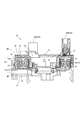
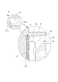
- FIG. 2 is a cross-sectional view taken along line AA in FIG.
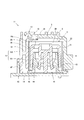
- FIG. 5 is an enlarged end view showing a part of FIG. 4. Action
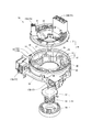
- the steering roll connector 10 of this embodiment includes a cable housing 11, a retainer 41, and a rotation lock unit 51.
- 1 and 2 are an external view and an exploded perspective view of the steering roll connector, respectively.
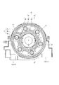
- FIG. 3 is a plan view of the steering roll connector in a state where a rotator described later is removed.
- FIG. 4 is a cross-sectional view taken along line AA in FIG.
- FIG. 4 is an enlarged end surface of a portion corresponding to the line BB in FIG. 5 in the steering roll connector.
- the cable housing 11 is configured in a substantially cylindrical shape in which an insertion hole H penetrating in the axial direction of a steering shaft (not shown) is formed at a central portion in plan view.
- the insertion hole H is formed with a diameter that allows insertion of a steering shaft supported by the steering column (not shown).
- a steering wheel for performing a rotation operation is fixed to the upper end portion of the steering shaft.
- the cable housing 11 includes a stator 12 and a rotator 13 that can rotate relative to each other. As shown in FIG. 2 to FIG. 5, an accommodation space S in which a flexible flat cable C (hereinafter referred to as “flat cable C”) is appropriately wound is configured inside the cable housing 11. Yes.
- flat cable C a flexible flat cable C
- the stator 12 is fixed to an appropriate member on the vehicle body side, for example, a combination bracket switch (not shown) of the steering column, and is attached so as to be rotatable relative to the steering wheel.
- the stator 12 includes a fixed side ring plate 14 formed in an annular shape as a bottom plate, and a cylindrical outer peripheral cylindrical portion 15 extending vertically from the outer peripheral edge of the fixed side ring plate 14.
- the outer peripheral edge of the stationary ring plate 14 and the lower end of the cylindrical portion 15 are integrally formed by fitting.
- the outer peripheral cylindrical portion 15 includes a cylindrical outer outer peripheral cylindrical portion 15o, and a cylindrical inner outer peripheral cylindrical portion 15i having a slightly smaller diameter than the outer outer peripheral cylindrical portion 15o.
- the outer peripheral cylindrical part 15o and the inner peripheral cylindrical part 15i are concentrically arranged so as to oppose each other in the radial direction.
- the outer peripheral cylindrical portion 15o and the inner peripheral cylindrical portion 15i are integrally connected by a connecting portion 18 at an intermediate portion in the axial direction of the steering wheel (the vertical direction in FIGS. 4 and 5).
- the gap formed between the outer peripheral cylinder part 15o and the inner outer cylinder part 15i in the radial direction is divided by the connecting part 18 in the vertical direction, and as shown in FIG. Grooves gu and gd are formed.
- a guide protruding piece 16 is formed in the shape of a bowl that protrudes toward the top and guides the flat cable C from above.
- the guide protruding piece 16 protrudes straight into the accommodation space S along the inner peripheral edge of the upper portion of the inner outer cylindrical portion 15i in an annular shape in plan view, but the lower surface 16u of the guide protruding piece 16 is radially inward. It is formed in a taper shape that inclines upward along.
- a stator side connector 17 is attached to the stator 12.
- the stator side connector 17 includes a first stator side connector 17A and a second stator side connector 17B.
- the first stator side connector 17A and the second stator side connector 17B are arranged outside the outer peripheral cylindrical portion 15 (outer outer peripheral cylindrical portion 15o) so that the respective connector connection ports face the same direction at a predetermined interval. Yes.
- the rotator 13 is composed of a rotating ring plate (top plate) 21 formed in a ring shape and a cylindrical inner peripheral cylindrical portion 22 extending vertically from the inner peripheral edge of the rotating ring plate 21.
- the rotator 13 is configured to rotate integrally with the steering wheel.
- the rotator 13 can rotate about the same axis as the rotation axis of the steering wheel with respect to the stator 12.
- the rotation-side ring plate 21 is disposed so as to face the fixed-side ring plate 14 in the direction of the rotation axis of the rotator 13.
- the direction of the rotating shaft of the rotator 13 is the same direction as the axial direction of the steering wheel described above (the vertical direction in FIGS. 4 and 5).
- the inner peripheral cylindrical portion 22 is disposed so as to face the outer peripheral cylindrical portion 15 in the radial direction.
- a rotator-side connector 23 ⁇ / b> B that rotates integrally with the rotation of the rotator 13 is attached to the rotator 13.
- the rotator-side connector 23 includes a first rotator-side connector 23A and a second rotator-side connector 23B.
- the first rotator-side connector 23A and the first stator-side connector 17A, and the second rotator-side connector 23B and the second stator-side connector 17B are electrically connected to each other by a flat cable C disposed in the accommodation space S. Has been.
- the stator side connector 17 is connected to a cable (not shown) drawn from an electric circuit or the like on the vehicle body side in a lower column cover (not shown).
- the rotator-side connector 23 is connected to a cable (not shown) drawn from an electric circuit such as a horn switch or an airbag unit, for example.
- the retainer 41 described above is composed of a plurality of rotating rollers 43 and a base ring 42, and is disposed in the accommodation space S so as to be rotatable around the rotation axis of the rotator 13.
- the rotation rollers 43 are provided in the same number as the roller support protrusions 45 described later, and are respectively supported by the roller support protrusions 45 so as to be rotatable about an axis parallel to the rotation axis of the rotator 13. ing.
- the base ring 42 includes a plate-shaped base ring main body 44 having an annular shape in plan view, a roller support protrusion 45, and a roller outer peripheral protrusion 46.
- the base ring main body 44 is disposed so as to be slidable in proximity to the stationary ring plate 14 and is configured to be rotatable relative to the stator 12.
- the roller support protrusion 45 protrudes upward in the circumferential direction of the base ring main body 44 so that the rotation roller 43 can be pivotally supported at equal intervals.
- the roller outer peripheral projection 46 guides a folded portion (a reversing portion Cr, which will be described later) where the flat cable C is folded around the rotating roller 43 as will be described later from the outer side with respect to the roller support protruding portion 45.
- the base ring main body 44 protrudes upward.
- the rotation lock unit 51 includes a lock body 52, a spring receiving sleeve 54, and a return spring 53 interposed between the lock body 52 and the spring receiving sleeve 54.
- the rotator 13 By pushing up the spring receiving sleeve 54 against the urging force of the return spring 53, the rotator 13 can be locked by the lock body 52 so as not to rotate relative to the stator 12, or the boss portion of the mandrel of the steering wheel By inserting (not shown), the lock by the lock body 52 can be released so as to allow relative rotation freely.
- the flat cable C is a flexible band-shaped transmission line in which a plurality of flat rectangular conductors Ca are arranged in parallel at a predetermined pitch and covered with an electrical insulator Cb.
- the flat cable C is provided with two in the accommodation space S, and is provided in a state where the two are overlapped and wound in the accommodation space S.
- One end of the two flat cables C in the length direction is connected to the first stator connector 17A side, and one end of the other flat cable C in the length direction is connected to the first flat cable C. It is connected to the second stator side connector 17B side (not shown).
- the other end in the length direction of one of the two flat cables C is connected to the first rotator side connector 23 side, and the other end in the length direction of the other flat cable C of the two.
- the side is connected to the second rotator side connector 23 side (not shown).
- the flat cable C is drawn into the housing space S from each of the first stator-side connector 17A and the second stator-side connector 17B in the housing space S, and as shown in FIGS.
- An outer winding portion Co that is wound along the inner peripheral surface of the outer peripheral cylindrical portion 15 (inner outer peripheral cylindrical portion 15i) of the stator 12 is formed on the outer side.
- the base end of the outer winding portion Co is fixed at the position of the stator side connector 17.
- the flat cable C is wound as a set of two in the accommodation space S.
- the flat cable C is simplified and only one is wound. Show.
- the flat cable C has a reversal portion Cr whose direction is reversed so as to be wound around one of the plurality of rotating rollers 43 in the middle of the length direction. Composed.
- the flat cable C is then configured with an inner winding portion Ci that is wound so that the other end in the length direction is inside the retainer 41 and along the outer peripheral surface of the inner peripheral cylindrical portion 22 of the rotator 13. As shown in FIGS. 3 to 5, the flat cable C is finally pulled out of the accommodation space S and connected to the first rotator side connector 23 ⁇ / b> A and the second rotator side connector 23 ⁇ / b> B side.
- the base end of the inner winding portion Ci is fixed at the position of the rotator side connector 23.
- the flat cable C is either wound or unwound between the outer winding portion Co and the inner winding portion Ci when the rotator 13 rotates with respect to the stator 12 inside the accommodation space S. Is done.
- the reversal portion Cr rotates appropriately with the retainer 41 so as to follow the change in the balance of the winding state between the outer winding portion Co and the inner winding portion Ci.
- the steering roll connector 10 can hold the flat cable C in a winding state in which the flat cable C is always aligned in the accommodation space S, and enables a smooth rotation operation of the steering wheel.
- the steering roll connector 10 described above can obtain various functions and effects as described below.
- the steering roll connector 10 is formed with the guide protruding piece 16 protruding in a bowl shape toward the accommodation space S at the upper part of the inner outer peripheral cylinder portion 15i.
- the guide protruding piece 16 has a bowl shape toward the accommodation space S (radially inward) above the upper end of the flat cable C wound along the radial direction in the accommodation space S in the inner peripheral cylindrical portion 15i. And at least the outer winding portion Co of the flat cable C is guided from above.
- the guide protrusion 16 guides the outer winding portion Co of the flat cable C from above even when the vehicle vibrates during traveling or the wound flat cable C bends upward. It can be avoided that the flat cable C wound in the accommodation space S collides with or rubs against the rotating side ring plate 21 of the rotator 13 to generate harsh sounds.
- both of the inner winding portions Ci may come into contact with the lower surface of the rotation-side ring plate 21 of the rotator 13 that rotates with respect to the stator 12, and as the number of contact points increases, a large collision sound or rubbing sound is generated. It becomes easy.
- the rotator 13 rotates with respect to the stator 12 as the steering wheel rotates.
- the outer winding portion Co of the flat cable C is wound and unwound on the inner peripheral surface of the inner peripheral cylinder portion 15i, and during this time, the outer winding portion Co is connected to the inner periphery of the inner outer peripheral cylinder portion 15i. And the outer periphery of the retainer 41 slide in the radial direction.
- the flat cable C protrudes from the guide. It can be kept in contact with the piece 16 with a small contact area, and generation of an harsh sound can be greatly suppressed.
- the lower surface 16u of the guide projecting piece 16 is formed in a taper shape that is inclined upward in the accommodating space S so as to be gradually separated from the cable in the radially inward direction.
- FIG. 6 is an operation explanatory view of the guide projecting piece 16. Specifically, FIG. 6 (a) is an enlarged view of a region X in FIG. 5, and FIG. 6 (b) is FIG. It is an enlarged view of the area
- the guide projecting piece 16 is formed in a shape different from that of the present embodiment so that the lower surface 16u of the guide projecting piece 16 projects straight inwardly in the radial direction (virtual in FIG. 6A).
- the upper end portion Cou of the outer winding portion Co may continue to contact the lower surface 160u of the guide protruding piece 160 as described above. And noise due to rubbing is likely to occur.
- the guide protruding piece 16 prevents the flat cable C from coming into contact with the rotator 13, and the contact area with the guide protruding piece 16 itself can be reduced as much as possible, thereby preventing damage due to wear of the flat cable C. be able to.
- the guide protrusion 16 has a simple bowl shape whose lower surface is inclined in a taper shape, the guide protrusion piece 16 can be easily configured without cost, and can be mass-produced by molding, for example. .
- the rotary connector device corresponds to the steering roll connector 10, and similarly,
- the cable wound around the outer periphery corresponds to the outer winding portion Co,
- the cable corresponds to the flexible flat cable C.
- the present invention is not limited to the above-described embodiment, and can be configured in various embodiments.
Landscapes
- Engineering & Computer Science (AREA)
- Mechanical Engineering (AREA)
- Electric Cable Arrangement Between Relatively Moving Parts (AREA)
- Steering Controls (AREA)
Abstract
L'invention porte sur un dispositif raccord rotatif qui peut permettre un déplacement silencieux et confortable, sans bruits gênants, même lorsqu'un câble plat et un boîtier de câble entrent en collision et frottent l'un contre l'autre en raison de la vibration d'un véhicule se déplaçant, et qui peut également empêcher un endommagement provoqué par l'usure du câble plat. Le dispositif raccord est configuré à partir de : un stator (12) et un rotor (13) qui tournent l'un par rapport à l'autre; et un espace de réception (S) à l'intérieur du stator (12) et du rotor (13), qui reçoit un câble (C) dans un état enroulé, ledit câble (C) connectant électriquement le côté rotor (13) et le côté stator (12). Une partie de guidage en saillie (16), qui fait saillie vers l'espace de réception (S) au-dessus du câble enroulé (C) et qui guide le câble (C) à partir du dessus, est formée sur la section supérieure d'une section tube périphérique externe (15) disposée sur le stator (12). La surface inférieure (16u) de la partie de guidage en saillie (16) se présente sous une forme qui est progressivement déformée vers le haut, en direction d'une pointe.
Priority Applications (3)
| Application Number | Priority Date | Filing Date | Title |
|---|---|---|---|
| CN201180016911.8A CN102823082B (zh) | 2010-03-30 | 2011-03-25 | 旋转连接器装置 |
| EP11762702.6A EP2555346B1 (fr) | 2010-03-30 | 2011-03-25 | Dispositif raccord rotatif |
| US13/632,899 US8851901B2 (en) | 2010-03-30 | 2012-10-01 | Rotary connector device |
Applications Claiming Priority (2)
| Application Number | Priority Date | Filing Date | Title |
|---|---|---|---|
| JP2010-078595 | 2010-03-30 | ||
| JP2010078595A JP5224404B2 (ja) | 2010-03-30 | 2010-03-30 | 回転コネクタ装置 |
Related Child Applications (1)
| Application Number | Title | Priority Date | Filing Date |
|---|---|---|---|
| US13/632,899 Continuation US8851901B2 (en) | 2010-03-30 | 2012-10-01 | Rotary connector device |
Publications (1)
| Publication Number | Publication Date |
|---|---|
| WO2011122471A1 true WO2011122471A1 (fr) | 2011-10-06 |
Family
ID=44712180
Family Applications (1)
| Application Number | Title | Priority Date | Filing Date |
|---|---|---|---|
| PCT/JP2011/057342 WO2011122471A1 (fr) | 2010-03-30 | 2011-03-25 | Dispositif raccord rotatif |
Country Status (5)
| Country | Link |
|---|---|
| US (1) | US8851901B2 (fr) |
| EP (1) | EP2555346B1 (fr) |
| JP (1) | JP5224404B2 (fr) |
| CN (1) | CN102823082B (fr) |
| WO (1) | WO2011122471A1 (fr) |
Cited By (1)
| Publication number | Priority date | Publication date | Assignee | Title |
|---|---|---|---|---|
| WO2013065633A1 (fr) * | 2011-10-31 | 2013-05-10 | 古河電気工業株式会社 | Dispositif de connecteur rotatif |
Families Citing this family (6)
| Publication number | Priority date | Publication date | Assignee | Title |
|---|---|---|---|---|
| JP5053433B2 (ja) * | 2010-11-19 | 2012-10-17 | 古河電気工業株式会社 | 回転コネクタ装置 |
| WO2015001837A1 (fr) * | 2013-07-04 | 2015-01-08 | 日産自動車株式会社 | Structure de routage de câblages d'alimentation de moteur pour roue entrainée par un moteur-roue |
| JP6928851B2 (ja) * | 2016-09-12 | 2021-09-01 | 古河電気工業株式会社 | 回転コネクタ装置 |
| JP6989515B2 (ja) * | 2016-11-09 | 2022-01-05 | 古河電気工業株式会社 | 接続構造体及び該接続構造体を備える回転コネクタ装置 |
| JP7371010B2 (ja) * | 2018-12-13 | 2023-10-30 | 古河電気工業株式会社 | 回転コネクタ装置 |
| US10867591B1 (en) * | 2019-09-30 | 2020-12-15 | Honda Motor Co., Ltd. | Vehicle horn assembly and method |
Citations (5)
| Publication number | Priority date | Publication date | Assignee | Title |
|---|---|---|---|---|
| JPH0955275A (ja) * | 1995-08-11 | 1997-02-25 | Yazaki Corp | 固定体と回転体との電気的接続装置 |
| JP2002345140A (ja) * | 2001-05-14 | 2002-11-29 | Auto Network Gijutsu Kenkyusho:Kk | ケーブルリール |
| JP2003022879A (ja) * | 2001-07-05 | 2003-01-24 | Alps Electric Co Ltd | 回転コネクタ |
| JP2009143491A (ja) * | 2007-12-17 | 2009-07-02 | Alps Electric Co Ltd | 回転コネクタ |
| JP2009217974A (ja) * | 2008-03-07 | 2009-09-24 | Alps Electric Co Ltd | 回転コネクタ |
Family Cites Families (24)
| Publication number | Priority date | Publication date | Assignee | Title |
|---|---|---|---|---|
| JP2507808B2 (ja) * | 1989-05-31 | 1996-06-19 | 古河電気工業株式会社 | コネクタ装置 |
| JPH06275354A (ja) * | 1993-03-22 | 1994-09-30 | Tokai Rika Co Ltd | ロールコネクタ |
| JP3241245B2 (ja) * | 1995-10-27 | 2001-12-25 | アルプス電気株式会社 | 回転コネクタ |
| EP1029744B1 (fr) * | 1995-10-27 | 2004-04-07 | Alps Electric Co., Ltd. | Connecteur rotatif |
| JP3403321B2 (ja) * | 1997-08-08 | 2003-05-06 | 株式会社オートネットワーク技術研究所 | 吸音材を備えたケーブルリールおよびケーブルリールの吸音材形成方法 |
| JP3717309B2 (ja) | 1998-08-20 | 2005-11-16 | 古河電気工業株式会社 | 回転コネクタ |
| JP4804608B2 (ja) * | 2000-02-15 | 2011-11-02 | 古河電気工業株式会社 | 回転コネクタ |
| JP2002075574A (ja) * | 2000-08-28 | 2002-03-15 | Yazaki Corp | 回転コネクタ |
| EP1247697A3 (fr) * | 2001-04-03 | 2003-10-22 | Tyco Electronics AMP GmbH | Connecteur rotatif |
| US6715707B2 (en) * | 2001-05-14 | 2004-04-06 | Autonetworks Technologies, Ltd. | Cable reel |
| JP4383244B2 (ja) * | 2004-05-13 | 2009-12-16 | 古河電気工業株式会社 | 回転コネクタ |
| JP2006120512A (ja) * | 2004-10-22 | 2006-05-11 | Alps Electric Co Ltd | 回転コネクタ |
| JP2009080958A (ja) * | 2007-09-25 | 2009-04-16 | Alps Electric Co Ltd | 回転コネクタ |
| JP4999105B2 (ja) * | 2008-02-12 | 2012-08-15 | 古河電気工業株式会社 | 回転コネクタ装置 |
| JP5117529B2 (ja) * | 2010-03-30 | 2013-01-16 | 古河電気工業株式会社 | 回転コネクタ装置 |
| JP5117528B2 (ja) * | 2010-03-30 | 2013-01-16 | 古河電気工業株式会社 | 回転コネクタ装置 |
| JP5065508B2 (ja) * | 2010-03-30 | 2012-11-07 | 古河電気工業株式会社 | 回転コネクタ装置 |
| JP5041447B2 (ja) * | 2010-03-30 | 2012-10-03 | 古河電気工業株式会社 | 回転コネクタ装置 |
| EP2571126B1 (fr) * | 2010-05-10 | 2018-11-28 | Furukawa Electric Co., Ltd. | Dispositif de connecteur rotatif |
| JP4974195B2 (ja) * | 2010-10-20 | 2012-07-11 | 古河電気工業株式会社 | 回転コネクタ装置 |
| JP5138022B2 (ja) * | 2010-11-18 | 2013-02-06 | 古河電気工業株式会社 | キャンセルカム構造及び回転コネクタ装置 |
| CN103210553B (zh) * | 2010-11-19 | 2015-08-19 | 古河电气工业株式会社 | 旋转连接器装置 |
| JP5053433B2 (ja) * | 2010-11-19 | 2012-10-17 | 古河電気工業株式会社 | 回転コネクタ装置 |
| JP5654025B2 (ja) * | 2011-03-09 | 2015-01-14 | 古河電気工業株式会社 | 回転コネクタ装置 |
-
2010
- 2010-03-30 JP JP2010078595A patent/JP5224404B2/ja active Active
-
2011
- 2011-03-25 CN CN201180016911.8A patent/CN102823082B/zh active Active
- 2011-03-25 WO PCT/JP2011/057342 patent/WO2011122471A1/fr active Application Filing
- 2011-03-25 EP EP11762702.6A patent/EP2555346B1/fr active Active
-
2012
- 2012-10-01 US US13/632,899 patent/US8851901B2/en active Active
Patent Citations (5)
| Publication number | Priority date | Publication date | Assignee | Title |
|---|---|---|---|---|
| JPH0955275A (ja) * | 1995-08-11 | 1997-02-25 | Yazaki Corp | 固定体と回転体との電気的接続装置 |
| JP2002345140A (ja) * | 2001-05-14 | 2002-11-29 | Auto Network Gijutsu Kenkyusho:Kk | ケーブルリール |
| JP2003022879A (ja) * | 2001-07-05 | 2003-01-24 | Alps Electric Co Ltd | 回転コネクタ |
| JP2009143491A (ja) * | 2007-12-17 | 2009-07-02 | Alps Electric Co Ltd | 回転コネクタ |
| JP2009217974A (ja) * | 2008-03-07 | 2009-09-24 | Alps Electric Co Ltd | 回転コネクタ |
Cited By (5)
| Publication number | Priority date | Publication date | Assignee | Title |
|---|---|---|---|---|
| WO2013065633A1 (fr) * | 2011-10-31 | 2013-05-10 | 古河電気工業株式会社 | Dispositif de connecteur rotatif |
| JP2013097987A (ja) * | 2011-10-31 | 2013-05-20 | Furukawa Electric Co Ltd:The | 回転コネクタ装置 |
| CN103262365A (zh) * | 2011-10-31 | 2013-08-21 | 古河电气工业株式会社 | 旋转连接器装置 |
| EP2775572A4 (fr) * | 2011-10-31 | 2015-06-17 | Furukawa Electric Co Ltd | Dispositif de connecteur rotatif |
| CN103262365B (zh) * | 2011-10-31 | 2015-09-09 | 古河电气工业株式会社 | 旋转连接器装置 |
Also Published As
| Publication number | Publication date |
|---|---|
| CN102823082B (zh) | 2015-06-10 |
| EP2555346A4 (fr) | 2014-04-30 |
| JP2011210615A (ja) | 2011-10-20 |
| US8851901B2 (en) | 2014-10-07 |
| CN102823082A (zh) | 2012-12-12 |
| EP2555346B1 (fr) | 2015-08-26 |
| JP5224404B2 (ja) | 2013-07-03 |
| EP2555346A1 (fr) | 2013-02-06 |
| US20130094172A1 (en) | 2013-04-18 |
Similar Documents
| Publication | Publication Date | Title |
|---|---|---|
| WO2011122471A1 (fr) | Dispositif raccord rotatif | |
| WO2011122472A1 (fr) | Unité de connecteur rotatif | |
| JP5117528B2 (ja) | 回転コネクタ装置 | |
| JP2011207402A5 (fr) | ||
| JP5117595B2 (ja) | 回転コネクタ装置 | |
| JP5019662B2 (ja) | 回転コネクタ装置 | |
| JP5053433B2 (ja) | 回転コネクタ装置 | |
| JP2011258546A5 (fr) | ||
| JP5624972B2 (ja) | 回転コネクタ装置 | |
| US20090203232A1 (en) | Rotating connector | |
| JP2010129285A (ja) | 回転コネクタ装置 | |
| JP3518995B2 (ja) | 回転コネクタ | |
| EP2693577B1 (fr) | Dispositif de raccord rotatif | |
| JP2009217974A (ja) | 回転コネクタ | |
| JP3234858B2 (ja) | 回転コネクタ | |
| JP2013187125A (ja) | 回転伝達機構及び回転コネクタ | |
| JPH08162240A (ja) | ケーブル用リール装置 | |
| JP2000077149A (ja) | 回転コネクタ | |
| JPH08180951A (ja) | ハンドルとステアリングコラム間の電気的接続装置 | |
| KR20000011392A (ko) | 회전커넥터 |
Legal Events
| Date | Code | Title | Description |
|---|---|---|---|
| WWE | Wipo information: entry into national phase |
Ref document number: 201180016911.8 Country of ref document: CN |
|
| 121 | Ep: the epo has been informed by wipo that ep was designated in this application |
Ref document number: 11762702 Country of ref document: EP Kind code of ref document: A1 |
|
| WWE | Wipo information: entry into national phase |
Ref document number: 2330/KOLNP/2012 Country of ref document: IN |
|
| NENP | Non-entry into the national phase |
Ref country code: DE |
|
| WWE | Wipo information: entry into national phase |
Ref document number: 2011762702 Country of ref document: EP |