WO2011122471A1 - Rotary connector device - Google Patents
Rotary connector device Download PDFInfo
- Publication number
- WO2011122471A1 WO2011122471A1 PCT/JP2011/057342 JP2011057342W WO2011122471A1 WO 2011122471 A1 WO2011122471 A1 WO 2011122471A1 JP 2011057342 W JP2011057342 W JP 2011057342W WO 2011122471 A1 WO2011122471 A1 WO 2011122471A1
- Authority
- WO
- WIPO (PCT)
- Prior art keywords
- rotator
- stator
- cable
- flat cable
- wound
- Prior art date
Links
Images

Classifications
-
- H—ELECTRICITY
- H02—GENERATION; CONVERSION OR DISTRIBUTION OF ELECTRIC POWER
- H02G—INSTALLATION OF ELECTRIC CABLES OR LINES, OR OF COMBINED OPTICAL AND ELECTRIC CABLES OR LINES
- H02G11/00—Arrangements of electric cables or lines between relatively-movable parts
- H02G11/02—Arrangements of electric cables or lines between relatively-movable parts using take-up reel or drum
-
- B—PERFORMING OPERATIONS; TRANSPORTING
- B60—VEHICLES IN GENERAL
- B60R—VEHICLES, VEHICLE FITTINGS, OR VEHICLE PARTS, NOT OTHERWISE PROVIDED FOR
- B60R16/00—Electric or fluid circuits specially adapted for vehicles and not otherwise provided for; Arrangement of elements of electric or fluid circuits specially adapted for vehicles and not otherwise provided for
- B60R16/02—Electric or fluid circuits specially adapted for vehicles and not otherwise provided for; Arrangement of elements of electric or fluid circuits specially adapted for vehicles and not otherwise provided for electric constitutive elements
- B60R16/023—Electric or fluid circuits specially adapted for vehicles and not otherwise provided for; Arrangement of elements of electric or fluid circuits specially adapted for vehicles and not otherwise provided for electric constitutive elements for transmission of signals between vehicle parts or subsystems
- B60R16/027—Electric or fluid circuits specially adapted for vehicles and not otherwise provided for; Arrangement of elements of electric or fluid circuits specially adapted for vehicles and not otherwise provided for electric constitutive elements for transmission of signals between vehicle parts or subsystems between relatively movable parts of the vehicle, e.g. between steering wheel and column
-
- H—ELECTRICITY
- H01—ELECTRIC ELEMENTS
- H01R—ELECTRICALLY-CONDUCTIVE CONNECTIONS; STRUCTURAL ASSOCIATIONS OF A PLURALITY OF MUTUALLY-INSULATED ELECTRICAL CONNECTING ELEMENTS; COUPLING DEVICES; CURRENT COLLECTORS
- H01R35/00—Flexible or turnable line connectors, i.e. the rotation angle being limited
- H01R35/02—Flexible line connectors without frictional contact members
- H01R35/025—Flexible line connectors without frictional contact members having a flexible conductor wound around a rotation axis
-
- H—ELECTRICITY
- H01—ELECTRIC ELEMENTS
- H01R—ELECTRICALLY-CONDUCTIVE CONNECTIONS; STRUCTURAL ASSOCIATIONS OF A PLURALITY OF MUTUALLY-INSULATED ELECTRICAL CONNECTING ELEMENTS; COUPLING DEVICES; CURRENT COLLECTORS
- H01R35/00—Flexible or turnable line connectors, i.e. the rotation angle being limited
- H01R35/04—Turnable line connectors with limited rotation angle with frictional contact members
Definitions
- the present invention relates to a rotary connector device mounted on a vehicle such as an automobile, and relates to a rotary connector device used for electrically connecting a steering wheel side and a vehicle body side.
- a rotating connector device such as a steering roll connector mounted on a vehicle such as an automobile includes a cable housing including a stator (fixed case) and a rotator (rotating case) that are coaxially assembled so as to be relatively rotatable. Yes.
- Rotational connector device has a cable housing with a stator fixed to the vehicle body side and a rotator assembled on the steering wheel side. Further, the rotary connector device is configured to electrically connect, for example, a horn module, an airbag module, and a power source between the vehicle body side and the steering wheel side via a flat cable housed in the housing space inside the cable housing. Is going.
- the rotary connector described in Patent Document 1 is also one of such rotary connector devices.
- a retainer (guide member) for guiding a flat cable (band-shaped transmission line) accommodated in an accommodation space (annular space) configured inside the cable housing is provided on the bottom surface of the accommodation space.
- the retainer includes a C-shaped plate-shaped guide ring arranged on the bottom surface of the housing space so as to be rotatable about the rotation axis of the rotator, and a rotation shaft of the rotator in each part that equally distributes the circumferential direction of the guide ring. It comprises a plurality of rollers rotatably supported around a parallel rotation axis.
- the flat cable is housed in the housing space in a wound state, the inner end in the radial direction is wound around the inner peripheral cylindrical portion (inner cylindrical shaft portion) of the rotator, and the outer end in the radial direction is the outer peripheral cylindrical portion (outer portion).
- the middle part is wound back in a U-shape.
- the flat cable is configured so that the inner and outer ends in the radial direction are wound and unwound around the inner and outer cylinders in the housing space, respectively. Since the retainer rotates in the circumferential direction in the annular space, it can be kept in the cable housing without being damaged.
- the flat cable is wound and unwound in the housing space, so that the wound flat cable slides in the radial direction. And the flat cable are rubbed intensely, and an harsh sound is likely to be generated.
- the flat cable when the flat cable is repeatedly contacted, the flat cable may be damaged due to wear.
- the present invention is harsh even if the flat cable wound in the accommodation space bends upward, or the flat cable collides with the cable housing or is rubbed due to vibration of the vehicle while traveling.
- An object is to provide a rotary connector device that can realize quiet and comfortable running without generating a noise and can prevent damage due to wear of a flat cable.
- the present invention comprises a rotator having an inner peripheral cylindrical portion and a stator having an outer peripheral cylindrical portion, and the stator and the rotator are integrally configured to be rotatable relative to each other, and the stator and the rotator Is a rotary connector device having a housing space for housing a cable for electrically connecting the rotator side and the stator side in a wound state, and wound around the upper portion of the outer peripheral cylindrical portion.
- a guide projecting piece that projects toward the housing space above the cable and that guides the cable wound around at least the outer periphery of the housing space from above is formed, and the lower surface of the guide projecting piece is formed on the guide projection. It is characterized by being formed in a shape that gradually deforms upward along the protruding direction of the piece.
- the lower surface of the guide protruding piece can be formed in a tapered shape that is inclined upward along the protruding direction.
- the lower surface of the guide protruding piece is not limited to the above-described tapered shape that is inclined upward along the protruding direction as long as the shape gradually deforms upward along the protruding direction of the guide protruding piece. It includes forming in various shapes such as a shape that deforms upward while curving along the direction.
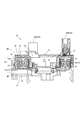
- FIG. 2 is a cross-sectional view taken along line AA in FIG.
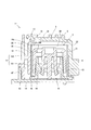
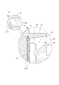
- FIG. 5 is an enlarged end view showing a part of FIG. 4. Action
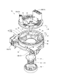
- the steering roll connector 10 of this embodiment includes a cable housing 11, a retainer 41, and a rotation lock unit 51.
- 1 and 2 are an external view and an exploded perspective view of the steering roll connector, respectively.
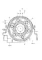
- FIG. 3 is a plan view of the steering roll connector in a state where a rotator described later is removed.
- FIG. 4 is a cross-sectional view taken along line AA in FIG.
- FIG. 4 is an enlarged end surface of a portion corresponding to the line BB in FIG. 5 in the steering roll connector.
- the cable housing 11 is configured in a substantially cylindrical shape in which an insertion hole H penetrating in the axial direction of a steering shaft (not shown) is formed at a central portion in plan view.
- the insertion hole H is formed with a diameter that allows insertion of a steering shaft supported by the steering column (not shown).
- a steering wheel for performing a rotation operation is fixed to the upper end portion of the steering shaft.
- the cable housing 11 includes a stator 12 and a rotator 13 that can rotate relative to each other. As shown in FIG. 2 to FIG. 5, an accommodation space S in which a flexible flat cable C (hereinafter referred to as “flat cable C”) is appropriately wound is configured inside the cable housing 11. Yes.
- flat cable C a flexible flat cable C
- the stator 12 is fixed to an appropriate member on the vehicle body side, for example, a combination bracket switch (not shown) of the steering column, and is attached so as to be rotatable relative to the steering wheel.
- the stator 12 includes a fixed side ring plate 14 formed in an annular shape as a bottom plate, and a cylindrical outer peripheral cylindrical portion 15 extending vertically from the outer peripheral edge of the fixed side ring plate 14.
- the outer peripheral edge of the stationary ring plate 14 and the lower end of the cylindrical portion 15 are integrally formed by fitting.
- the outer peripheral cylindrical portion 15 includes a cylindrical outer outer peripheral cylindrical portion 15o, and a cylindrical inner outer peripheral cylindrical portion 15i having a slightly smaller diameter than the outer outer peripheral cylindrical portion 15o.
- the outer peripheral cylindrical part 15o and the inner peripheral cylindrical part 15i are concentrically arranged so as to oppose each other in the radial direction.
- the outer peripheral cylindrical portion 15o and the inner peripheral cylindrical portion 15i are integrally connected by a connecting portion 18 at an intermediate portion in the axial direction of the steering wheel (the vertical direction in FIGS. 4 and 5).
- the gap formed between the outer peripheral cylinder part 15o and the inner outer cylinder part 15i in the radial direction is divided by the connecting part 18 in the vertical direction, and as shown in FIG. Grooves gu and gd are formed.
- a guide protruding piece 16 is formed in the shape of a bowl that protrudes toward the top and guides the flat cable C from above.
- the guide protruding piece 16 protrudes straight into the accommodation space S along the inner peripheral edge of the upper portion of the inner outer cylindrical portion 15i in an annular shape in plan view, but the lower surface 16u of the guide protruding piece 16 is radially inward. It is formed in a taper shape that inclines upward along.
- a stator side connector 17 is attached to the stator 12.
- the stator side connector 17 includes a first stator side connector 17A and a second stator side connector 17B.
- the first stator side connector 17A and the second stator side connector 17B are arranged outside the outer peripheral cylindrical portion 15 (outer outer peripheral cylindrical portion 15o) so that the respective connector connection ports face the same direction at a predetermined interval. Yes.
- the rotator 13 is composed of a rotating ring plate (top plate) 21 formed in a ring shape and a cylindrical inner peripheral cylindrical portion 22 extending vertically from the inner peripheral edge of the rotating ring plate 21.
- the rotator 13 is configured to rotate integrally with the steering wheel.
- the rotator 13 can rotate about the same axis as the rotation axis of the steering wheel with respect to the stator 12.
- the rotation-side ring plate 21 is disposed so as to face the fixed-side ring plate 14 in the direction of the rotation axis of the rotator 13.
- the direction of the rotating shaft of the rotator 13 is the same direction as the axial direction of the steering wheel described above (the vertical direction in FIGS. 4 and 5).
- the inner peripheral cylindrical portion 22 is disposed so as to face the outer peripheral cylindrical portion 15 in the radial direction.
- a rotator-side connector 23 ⁇ / b> B that rotates integrally with the rotation of the rotator 13 is attached to the rotator 13.
- the rotator-side connector 23 includes a first rotator-side connector 23A and a second rotator-side connector 23B.
- the first rotator-side connector 23A and the first stator-side connector 17A, and the second rotator-side connector 23B and the second stator-side connector 17B are electrically connected to each other by a flat cable C disposed in the accommodation space S. Has been.
- the stator side connector 17 is connected to a cable (not shown) drawn from an electric circuit or the like on the vehicle body side in a lower column cover (not shown).
- the rotator-side connector 23 is connected to a cable (not shown) drawn from an electric circuit such as a horn switch or an airbag unit, for example.
- the retainer 41 described above is composed of a plurality of rotating rollers 43 and a base ring 42, and is disposed in the accommodation space S so as to be rotatable around the rotation axis of the rotator 13.
- the rotation rollers 43 are provided in the same number as the roller support protrusions 45 described later, and are respectively supported by the roller support protrusions 45 so as to be rotatable about an axis parallel to the rotation axis of the rotator 13. ing.
- the base ring 42 includes a plate-shaped base ring main body 44 having an annular shape in plan view, a roller support protrusion 45, and a roller outer peripheral protrusion 46.
- the base ring main body 44 is disposed so as to be slidable in proximity to the stationary ring plate 14 and is configured to be rotatable relative to the stator 12.
- the roller support protrusion 45 protrudes upward in the circumferential direction of the base ring main body 44 so that the rotation roller 43 can be pivotally supported at equal intervals.
- the roller outer peripheral projection 46 guides a folded portion (a reversing portion Cr, which will be described later) where the flat cable C is folded around the rotating roller 43 as will be described later from the outer side with respect to the roller support protruding portion 45.
- the base ring main body 44 protrudes upward.
- the rotation lock unit 51 includes a lock body 52, a spring receiving sleeve 54, and a return spring 53 interposed between the lock body 52 and the spring receiving sleeve 54.
- the rotator 13 By pushing up the spring receiving sleeve 54 against the urging force of the return spring 53, the rotator 13 can be locked by the lock body 52 so as not to rotate relative to the stator 12, or the boss portion of the mandrel of the steering wheel By inserting (not shown), the lock by the lock body 52 can be released so as to allow relative rotation freely.
- the flat cable C is a flexible band-shaped transmission line in which a plurality of flat rectangular conductors Ca are arranged in parallel at a predetermined pitch and covered with an electrical insulator Cb.
- the flat cable C is provided with two in the accommodation space S, and is provided in a state where the two are overlapped and wound in the accommodation space S.
- One end of the two flat cables C in the length direction is connected to the first stator connector 17A side, and one end of the other flat cable C in the length direction is connected to the first flat cable C. It is connected to the second stator side connector 17B side (not shown).
- the other end in the length direction of one of the two flat cables C is connected to the first rotator side connector 23 side, and the other end in the length direction of the other flat cable C of the two.
- the side is connected to the second rotator side connector 23 side (not shown).
- the flat cable C is drawn into the housing space S from each of the first stator-side connector 17A and the second stator-side connector 17B in the housing space S, and as shown in FIGS.
- An outer winding portion Co that is wound along the inner peripheral surface of the outer peripheral cylindrical portion 15 (inner outer peripheral cylindrical portion 15i) of the stator 12 is formed on the outer side.
- the base end of the outer winding portion Co is fixed at the position of the stator side connector 17.
- the flat cable C is wound as a set of two in the accommodation space S.
- the flat cable C is simplified and only one is wound. Show.
- the flat cable C has a reversal portion Cr whose direction is reversed so as to be wound around one of the plurality of rotating rollers 43 in the middle of the length direction. Composed.
- the flat cable C is then configured with an inner winding portion Ci that is wound so that the other end in the length direction is inside the retainer 41 and along the outer peripheral surface of the inner peripheral cylindrical portion 22 of the rotator 13. As shown in FIGS. 3 to 5, the flat cable C is finally pulled out of the accommodation space S and connected to the first rotator side connector 23 ⁇ / b> A and the second rotator side connector 23 ⁇ / b> B side.
- the base end of the inner winding portion Ci is fixed at the position of the rotator side connector 23.
- the flat cable C is either wound or unwound between the outer winding portion Co and the inner winding portion Ci when the rotator 13 rotates with respect to the stator 12 inside the accommodation space S. Is done.
- the reversal portion Cr rotates appropriately with the retainer 41 so as to follow the change in the balance of the winding state between the outer winding portion Co and the inner winding portion Ci.
- the steering roll connector 10 can hold the flat cable C in a winding state in which the flat cable C is always aligned in the accommodation space S, and enables a smooth rotation operation of the steering wheel.
- the steering roll connector 10 described above can obtain various functions and effects as described below.
- the steering roll connector 10 is formed with the guide protruding piece 16 protruding in a bowl shape toward the accommodation space S at the upper part of the inner outer peripheral cylinder portion 15i.
- the guide protruding piece 16 has a bowl shape toward the accommodation space S (radially inward) above the upper end of the flat cable C wound along the radial direction in the accommodation space S in the inner peripheral cylindrical portion 15i. And at least the outer winding portion Co of the flat cable C is guided from above.
- the guide protrusion 16 guides the outer winding portion Co of the flat cable C from above even when the vehicle vibrates during traveling or the wound flat cable C bends upward. It can be avoided that the flat cable C wound in the accommodation space S collides with or rubs against the rotating side ring plate 21 of the rotator 13 to generate harsh sounds.
- both of the inner winding portions Ci may come into contact with the lower surface of the rotation-side ring plate 21 of the rotator 13 that rotates with respect to the stator 12, and as the number of contact points increases, a large collision sound or rubbing sound is generated. It becomes easy.
- the rotator 13 rotates with respect to the stator 12 as the steering wheel rotates.
- the outer winding portion Co of the flat cable C is wound and unwound on the inner peripheral surface of the inner peripheral cylinder portion 15i, and during this time, the outer winding portion Co is connected to the inner periphery of the inner outer peripheral cylinder portion 15i. And the outer periphery of the retainer 41 slide in the radial direction.
- the flat cable C protrudes from the guide. It can be kept in contact with the piece 16 with a small contact area, and generation of an harsh sound can be greatly suppressed.
- the lower surface 16u of the guide projecting piece 16 is formed in a taper shape that is inclined upward in the accommodating space S so as to be gradually separated from the cable in the radially inward direction.
- FIG. 6 is an operation explanatory view of the guide projecting piece 16. Specifically, FIG. 6 (a) is an enlarged view of a region X in FIG. 5, and FIG. 6 (b) is FIG. It is an enlarged view of the area
- the guide projecting piece 16 is formed in a shape different from that of the present embodiment so that the lower surface 16u of the guide projecting piece 16 projects straight inwardly in the radial direction (virtual in FIG. 6A).
- the upper end portion Cou of the outer winding portion Co may continue to contact the lower surface 160u of the guide protruding piece 160 as described above. And noise due to rubbing is likely to occur.
- the guide protruding piece 16 prevents the flat cable C from coming into contact with the rotator 13, and the contact area with the guide protruding piece 16 itself can be reduced as much as possible, thereby preventing damage due to wear of the flat cable C. be able to.
- the guide protrusion 16 has a simple bowl shape whose lower surface is inclined in a taper shape, the guide protrusion piece 16 can be easily configured without cost, and can be mass-produced by molding, for example. .
- the rotary connector device corresponds to the steering roll connector 10, and similarly,
- the cable wound around the outer periphery corresponds to the outer winding portion Co,
- the cable corresponds to the flexible flat cable C.
- the present invention is not limited to the above-described embodiment, and can be configured in various embodiments.
Abstract
The disclosed rotary connector device can enable quiet and comfortable travel in which unpleasant noises do not occur, even when a flat cable and a cable housing collide and rub off each other due to the vibration of a travelling vehicle, and can also prevent damage caused by the wear of the flat cable. The connector device is configured from: a stator (12) and a rotator (13) which rotate relative to each other; and an accommodation space (S), inside the stator (12) and the rotator (13), which accommodates a cable (C) in a wound state, said cable (C) electrically connecting the rotator (13) side and the stator (12) side. A guide protruding part (16) which protrudes towards the accommodation space (S) above the wound cable (C), and which guides the cable (C) from above, is formed on the upper section of an outer peripheral tube section (15) provided on the stator (12). The under surface (16u) of the guide protrusion part (16) is formed in a shape that is gradually deformed upwards towards a tip.
Description
この発明は、自動車等の車両に装着される回転コネクタ装置に関し、ステアリングホイール側と車体側との間を電気的に接続するために用いる回転コネクタ装置に関する。
The present invention relates to a rotary connector device mounted on a vehicle such as an automobile, and relates to a rotary connector device used for electrically connecting a steering wheel side and a vehicle body side.
自動車等の車両に装着されるステアリングロールコネクタなどの回転コネクタ装置は、相対的に回転可能に同軸上に組み付けられるステータ(固定ケース)とロテータ(回転ケース)とで構成されるケーブルハウジングを備えている。
BACKGROUND ART A rotating connector device such as a steering roll connector mounted on a vehicle such as an automobile includes a cable housing including a stator (fixed case) and a rotator (rotating case) that are coaxially assembled so as to be relatively rotatable. Yes.
回転コネクタ装置は、ケーブルハウジングのうち、ステータが車体側に固定され、ロテータがステアリングホイール側に組み付けられている。さらに、回転コネクタ装置は、ケーブルハウジング内部の収容空間に収容されたフラットケーブルを介して、車体側とステアリングホイール側との間の例えば、ホーンモジュール、エアバッグモジュール、電源等の電気的な接続を行っている。
Rotational connector device has a cable housing with a stator fixed to the vehicle body side and a rotator assembled on the steering wheel side. Further, the rotary connector device is configured to electrically connect, for example, a horn module, an airbag module, and a power source between the vehicle body side and the steering wheel side via a flat cable housed in the housing space inside the cable housing. Is going.
特許文献1に記載の回転コネクタもこのような回転コネクタ装置の1つである。
特許文献1に記載の回転コネクタは、ケーブルハウジングの内部に構成される収容空間(環状の空間)に収容されたフラットケーブル(帯状伝送線)を案内するリテーナ(案内部材)が収容空間の底面に配置されている。
リテーナは、ロテータの回転軸回りに回転自在に収容空間の底面に配置された平面視C型の板状のガイドリングと、該ガイドリングの周方向を等分配する各部において、ロテータの回転軸と平行な回転軸回りに回転自在に軸支された複数のローラとで構成している。 The rotary connector described in Patent Document 1 is also one of such rotary connector devices.
In the rotary connector described in Patent Document 1, a retainer (guide member) for guiding a flat cable (band-shaped transmission line) accommodated in an accommodation space (annular space) configured inside the cable housing is provided on the bottom surface of the accommodation space. Has been placed.
The retainer includes a C-shaped plate-shaped guide ring arranged on the bottom surface of the housing space so as to be rotatable about the rotation axis of the rotator, and a rotation shaft of the rotator in each part that equally distributes the circumferential direction of the guide ring. It comprises a plurality of rollers rotatably supported around a parallel rotation axis.
フラットケーブルは、収容空間に巻回状態で収容され、その半径方向の内端がロテータの内周筒部(内筒軸部)に巻き付けられ、半径方向の外端がステータの外周筒部(外筒部)に巻き付けられ、中間がU字状に巻き返されている。
そしてステアリングホイールの回転操作に伴ってフラットケーブルは、収容空間において、半径方向の内端と外端とがそれぞれ内周筒部、外周筒部に対する巻き付けと巻き解きが行われ、それに追従するように、リテーナが環状空間を周方向に回転することでケーブルハウジングに損傷なく収容された状態を保つことができる。 The flat cable is housed in the housing space in a wound state, the inner end in the radial direction is wound around the inner peripheral cylindrical portion (inner cylindrical shaft portion) of the rotator, and the outer end in the radial direction is the outer peripheral cylindrical portion (outer portion). The middle part is wound back in a U-shape.
As the steering wheel rotates, the flat cable is configured so that the inner and outer ends in the radial direction are wound and unwound around the inner and outer cylinders in the housing space, respectively. Since the retainer rotates in the circumferential direction in the annular space, it can be kept in the cable housing without being damaged.
しかし、収容空間に巻回された状態のフラットケーブルが上方へ撓んだり、走行中に車両が振動するなどしたとき、該フラットケーブルの上端部が収容空間の上方を覆うロテータの上フランジ(天板)に接触することがあり、接触により耳障りな音が発するという難点を有していた。
特に、ステアリングホイール操作時には、ステータに対してロテータが回転するため、フラットケーブルがロテータに接触する際には、回転している状態のロテータに対して接触することになり、ロテータとフラットケーブルとが擦れる(摺動する)ため、耳障りな音が発生し易くなる。 However, when the flat cable wound in the accommodation space bends upward or the vehicle vibrates during traveling, the upper flange of the rotator (the top of the rotator) covers the upper part of the accommodation space. Plate), and there is a problem that an irritating sound is generated by the contact.
In particular, when the steering wheel is operated, the rotator rotates with respect to the stator. Therefore, when the flat cable comes into contact with the rotator, it comes into contact with the rotating rotator. Since it rubs (slids), an harsh sound is likely to occur.
しかも、ステータに対してロテータが回転している際には、収容空間では、フラットケーブルの巻き付けと巻き解きが行われることで、巻回された状態のフラットケーブルが半径方向にスライドするため、ロテータとフラットケーブルとの擦れが激しくなり、さらに耳障りな音が発し易くなる。
Moreover, when the rotator is rotating with respect to the stator, the flat cable is wound and unwound in the housing space, so that the wound flat cable slides in the radial direction. And the flat cable are rubbed intensely, and an harsh sound is likely to be generated.
このように運転中に耳障りな音が発生することで快適な運転の妨げになるという難点を有していた。
As described above, there was a problem that an unpleasant sound was generated during driving, which hindered comfortable driving.
さらにまた、フラットケーブルが繰り返し接触すると、磨耗により該フラットケーブルが損傷するおそれがあるという難点も有していた。
Furthermore, when the flat cable is repeatedly contacted, the flat cable may be damaged due to wear.
そこで本発明は、収容空間に巻回された状態のフラットケーブルが上方へ撓んだり、走行中に車両が振動するなどにより、フラットケーブルがケーブルハウジングに衝突したり、擦れるなどしても、耳障りな音が発することがなく静粛で快適な走行を実現することができ、さらに、フラットケーブルの磨耗による損傷を防ぐことができる回転コネクタ装置の提供を目的とする。
Therefore, the present invention is harsh even if the flat cable wound in the accommodation space bends upward, or the flat cable collides with the cable housing or is rubbed due to vibration of the vehicle while traveling. An object is to provide a rotary connector device that can realize quiet and comfortable running without generating a noise and can prevent damage due to wear of a flat cable.
本発明は、内周筒部を備えたロテータと、外周筒部を備えたステータとを構成し、前記ステータと前記ロテータとを、互いに相対回転自在に一体に構成し、前記ステータと前記ロテータとの内部に、該ロテータ側と該ステータ側とを電気的に接続するケーブルを巻き回した状態で収容する収容空間を構成した回転コネクタ装置であって、前記外周筒部の上部に、巻き回した前記ケーブルよりも上方で前記収容空間に向けて突出し、少なくとも前記収容空間の外周付近で巻き回した前記ケーブルを上方からガイドするガイド突出片を形成し、前記ガイド突出片の下面を、該ガイド突起片の突出方向へ沿って徐々に上方へ変形する形状で形成したことを特徴とする。
The present invention comprises a rotator having an inner peripheral cylindrical portion and a stator having an outer peripheral cylindrical portion, and the stator and the rotator are integrally configured to be rotatable relative to each other, and the stator and the rotator Is a rotary connector device having a housing space for housing a cable for electrically connecting the rotator side and the stator side in a wound state, and wound around the upper portion of the outer peripheral cylindrical portion. A guide projecting piece that projects toward the housing space above the cable and that guides the cable wound around at least the outer periphery of the housing space from above is formed, and the lower surface of the guide projecting piece is formed on the guide projection. It is characterized by being formed in a shape that gradually deforms upward along the protruding direction of the piece.
この発明の態様として、前記ガイド突出片の下面を、前記突出方向へ沿って上方へと傾斜するテーパ形状で形成することができる。
As an aspect of the present invention, the lower surface of the guide protruding piece can be formed in a tapered shape that is inclined upward along the protruding direction.
前記ガイド突出片の下面は、前記ガイド突出片の突出方向へ沿って徐々に上方へ変形する形状であれば、該突出方向へ沿って上方へと傾斜する上述したテーパ形状に限らず、該突出方向へ沿って湾曲しながら上方へと変形する形状など様々な形状で形成することを含む。
The lower surface of the guide protruding piece is not limited to the above-described tapered shape that is inclined upward along the protruding direction as long as the shape gradually deforms upward along the protruding direction of the guide protruding piece. It includes forming in various shapes such as a shape that deforms upward while curving along the direction.
この発明によれば、収容空間に巻回された状態のフラットケーブルが上方へ撓んだり、走行中に車両が振動するなどにより、フラットケーブルがケーブルハウジングに衝突したり、擦れるなどしても、耳障りな音が発することがなく静粛で快適な走行を実現することができ、さらに、フラットケーブルの磨耗による損傷を防ぐことができる回転コネクタ装置を提供することができる。
According to this invention, even when the flat cable wound in the accommodation space bends upward, or the flat cable collides with the cable housing or rubs due to vibration of the vehicle during traveling, It is possible to provide a rotary connector device that can realize quiet and comfortable running without generating an harsh sound, and that can prevent damage due to wear of the flat cable.
この発明の一実施形態を、以下図面を用いて説明する。
本実施形態のステアリングロールコネクタ10(SRC)は、図1及至図5に示すように、ケーブルハウジング11と、リテーナ41と、回転ロックユニット51とで構成している。
なお、図1、図2は、前記ステアリングロールコネクタのそれぞれ外観図、分解斜視図である。図3は、後述するロテータを外した状態の前記ステアリングロールコネクタの平面図である。図4は、図1中のA-A線矢視断面図である。図4は、前記ステアリングロールコネクタにおける、図5中のB-B線に対応する部分の拡大端面である。 An embodiment of the present invention will be described below with reference to the drawings.
As shown in FIGS. 1 to 5, the steering roll connector 10 (SRC) of this embodiment includes acable housing 11, a retainer 41, and a rotation lock unit 51.
1 and 2 are an external view and an exploded perspective view of the steering roll connector, respectively. FIG. 3 is a plan view of the steering roll connector in a state where a rotator described later is removed. FIG. 4 is a cross-sectional view taken along line AA in FIG. FIG. 4 is an enlarged end surface of a portion corresponding to the line BB in FIG. 5 in the steering roll connector.
本実施形態のステアリングロールコネクタ10(SRC)は、図1及至図5に示すように、ケーブルハウジング11と、リテーナ41と、回転ロックユニット51とで構成している。
なお、図1、図2は、前記ステアリングロールコネクタのそれぞれ外観図、分解斜視図である。図3は、後述するロテータを外した状態の前記ステアリングロールコネクタの平面図である。図4は、図1中のA-A線矢視断面図である。図4は、前記ステアリングロールコネクタにおける、図5中のB-B線に対応する部分の拡大端面である。 An embodiment of the present invention will be described below with reference to the drawings.
As shown in FIGS. 1 to 5, the steering roll connector 10 (SRC) of this embodiment includes a
1 and 2 are an external view and an exploded perspective view of the steering roll connector, respectively. FIG. 3 is a plan view of the steering roll connector in a state where a rotator described later is removed. FIG. 4 is a cross-sectional view taken along line AA in FIG. FIG. 4 is an enlarged end surface of a portion corresponding to the line BB in FIG. 5 in the steering roll connector.
ケーブルハウジング11は、平面視中央部分にステアリングシャフト(図示省略)の軸方向に貫通した差込孔Hが形成された略円筒状の形態で構成されている。差込孔Hは、前記ステアリングコラム(図示省略)に支持されたステアリングシャフトの挿入を許容する径で形成されている。
なお、前記ステアリングシャフトの上端部には、回転操作を行うためのステアリングホイールが固定されている。 Thecable housing 11 is configured in a substantially cylindrical shape in which an insertion hole H penetrating in the axial direction of a steering shaft (not shown) is formed at a central portion in plan view. The insertion hole H is formed with a diameter that allows insertion of a steering shaft supported by the steering column (not shown).
A steering wheel for performing a rotation operation is fixed to the upper end portion of the steering shaft.
なお、前記ステアリングシャフトの上端部には、回転操作を行うためのステアリングホイールが固定されている。 The
A steering wheel for performing a rotation operation is fixed to the upper end portion of the steering shaft.
ケーブルハウジング11は、互いに相対回転可能なステータ12とロテータ13とで構成している。ケーブルハウジング11の内部には、図2及至図5に示すように、フレキシブルフラットケーブルC(以下、「フラットケーブルC」という。)が適宜巻かれた状態で収容される収容空間Sが構成されている。
The cable housing 11 includes a stator 12 and a rotator 13 that can rotate relative to each other. As shown in FIG. 2 to FIG. 5, an accommodation space S in which a flexible flat cable C (hereinafter referred to as “flat cable C”) is appropriately wound is configured inside the cable housing 11. Yes.
ステータ12は、車体側の適宜の部材、例えばステアリングコラムのコンビネーションブラケットスイッチ(図示省略)に固定され、ステアリングホイールに対して相対回転可能に取り付けられている。前記ステータ12は、底板として環状に形成した固定側リング板14と、この固定側リング板14の外周縁から垂直に延びる円筒状の外周筒部15とで構成されている。固定側リング板14の外周外周縁と筒部15の下端とは嵌合により一体に構成している。
The stator 12 is fixed to an appropriate member on the vehicle body side, for example, a combination bracket switch (not shown) of the steering column, and is attached so as to be rotatable relative to the steering wheel. The stator 12 includes a fixed side ring plate 14 formed in an annular shape as a bottom plate, and a cylindrical outer peripheral cylindrical portion 15 extending vertically from the outer peripheral edge of the fixed side ring plate 14. The outer peripheral edge of the stationary ring plate 14 and the lower end of the cylindrical portion 15 are integrally formed by fitting.
外周筒部15は、図4、及び、図5に示すように、円筒状の外側外周筒部15oと、該外側外周筒部15oよりも僅かに小径である円筒状の内側外周筒部15iとで構成され、外側外周筒部15oと内側外周筒部15iとが半径方向において近接して対向するよう同心円状に配置した2層構造で構成されている。
As shown in FIGS. 4 and 5, the outer peripheral cylindrical portion 15 includes a cylindrical outer outer peripheral cylindrical portion 15o, and a cylindrical inner outer peripheral cylindrical portion 15i having a slightly smaller diameter than the outer outer peripheral cylindrical portion 15o. The outer peripheral cylindrical part 15o and the inner peripheral cylindrical part 15i are concentrically arranged so as to oppose each other in the radial direction.
外側外周筒部15oと内側外周筒部15iとは、ステアリングホイールの軸方向(図4、及び、図5中の上下方向)の中間部において連結部18により一体に連結されている。外側外周筒部15oと内側外周筒部15iとの半径方向の間に構成される隙間は、連結部18により上下方向に分断され、図5に示すように、上下各側向けて開口した2つの溝gu,gdが構成されている。
The outer peripheral cylindrical portion 15o and the inner peripheral cylindrical portion 15i are integrally connected by a connecting portion 18 at an intermediate portion in the axial direction of the steering wheel (the vertical direction in FIGS. 4 and 5). The gap formed between the outer peripheral cylinder part 15o and the inner outer cylinder part 15i in the radial direction is divided by the connecting part 18 in the vertical direction, and as shown in FIG. Grooves gu and gd are formed.
また、前記内側外周筒部15iの上部には、図5に示すように、収容空間Sで巻き回したフラットケーブルCよりも上方で該収容空間Sに向けて半径方向の内側(径内方向)へ突出し、該フラットケーブルCを上方からガイドするガイド突出片16が鍔状に形成されている。
Further, at the upper part of the inner outer peripheral cylinder portion 15i, as shown in FIG. 5, the inner side in the radial direction (inward diameter direction) toward the accommodation space S above the flat cable C wound in the accommodation space S. A guide protruding piece 16 is formed in the shape of a bowl that protrudes toward the top and guides the flat cable C from above.
ガイド突出片16は、平面視円環状に内側外周筒部15iの上部の内周縁に沿って収容空間Sへ真直ぐに突出しているが、前記ガイド突出片16の下面16uは、半径方向の内側に沿って上方へ傾斜するテ―パ形状で形成されている。
The guide protruding piece 16 protrudes straight into the accommodation space S along the inner peripheral edge of the upper portion of the inner outer cylindrical portion 15i in an annular shape in plan view, but the lower surface 16u of the guide protruding piece 16 is radially inward. It is formed in a taper shape that inclines upward along.
ステータ12には、ステータ側コネクタ17が取り付けられている。
ステータ側コネクタ17は、第1ステータ側コネクタ17Aと第2ステータ側コネクタ17Bとで構成している。第1ステータ側コネクタ17Aと第2ステータ側コネクタ17Bとは、所定間隔を隔ててそれぞれのコネクタ接続口が同じ方向を向くように外周筒部15(外側外周筒部15o)の外側に配置されている。 Astator side connector 17 is attached to the stator 12.
Thestator side connector 17 includes a first stator side connector 17A and a second stator side connector 17B. The first stator side connector 17A and the second stator side connector 17B are arranged outside the outer peripheral cylindrical portion 15 (outer outer peripheral cylindrical portion 15o) so that the respective connector connection ports face the same direction at a predetermined interval. Yes.
ステータ側コネクタ17は、第1ステータ側コネクタ17Aと第2ステータ側コネクタ17Bとで構成している。第1ステータ側コネクタ17Aと第2ステータ側コネクタ17Bとは、所定間隔を隔ててそれぞれのコネクタ接続口が同じ方向を向くように外周筒部15(外側外周筒部15o)の外側に配置されている。 A
The
前記ロテータ13は、リング状に形成された回転側リング板(天板)21と、この回転側リング板21の内周縁から垂直に延びる円筒状の内周筒部22とで構成している。そしてロテータ13は、ステアリングホイールとともに一体的に回転するように構成されている。ロテータ13は、ステータ12に対して前記ステアリングホイールの回転軸と同一の軸回りに回転することができる。
The rotator 13 is composed of a rotating ring plate (top plate) 21 formed in a ring shape and a cylindrical inner peripheral cylindrical portion 22 extending vertically from the inner peripheral edge of the rotating ring plate 21. The rotator 13 is configured to rotate integrally with the steering wheel. The rotator 13 can rotate about the same axis as the rotation axis of the steering wheel with respect to the stator 12.
回転側リング板21は、ロテータ13の回転軸の方向で前記固定側リング板14に対面するように配置されている。
なお、ロテータ13の回転軸の方向は、上述したステアリングホイールの軸方向(図4、及び、図5中の上下方向)と同じ方向である。 The rotation-side ring plate 21 is disposed so as to face the fixed-side ring plate 14 in the direction of the rotation axis of the rotator 13.
In addition, the direction of the rotating shaft of therotator 13 is the same direction as the axial direction of the steering wheel described above (the vertical direction in FIGS. 4 and 5).
なお、ロテータ13の回転軸の方向は、上述したステアリングホイールの軸方向(図4、及び、図5中の上下方向)と同じ方向である。 The rotation-
In addition, the direction of the rotating shaft of the
また、前記内周筒部22は、外周筒部15と半径方向で対面するように配置されている。
Further, the inner peripheral cylindrical portion 22 is disposed so as to face the outer peripheral cylindrical portion 15 in the radial direction.
ロテータ13には、該ロテータ13の回転に伴って一体的に回転するロテータ側コネクタ23Bが取り付けられる。
ロテータ側コネクタ23は、第1ロテータ側コネクタ23Aと第2ロテータ側コネクタ23Bとで構成している。 A rotator-side connector 23 </ b> B that rotates integrally with the rotation of the rotator 13 is attached to the rotator 13.
The rotator-side connector 23 includes a first rotator-side connector 23A and a second rotator-side connector 23B.
ロテータ側コネクタ23は、第1ロテータ側コネクタ23Aと第2ロテータ側コネクタ23Bとで構成している。 A rotator-
The rotator-
第1ロテータ側コネクタ23Aと第1ステータ側コネクタ17A、及び、第2ロテータ側コネクタ23Bと第2ステータ側コネクタ17Bとは、それぞれ収容空間Sに配置されたフラットケーブルCによって相互に電気的に接続されている。
The first rotator-side connector 23A and the first stator-side connector 17A, and the second rotator-side connector 23B and the second stator-side connector 17B are electrically connected to each other by a flat cable C disposed in the accommodation space S. Has been.
ステータ側コネクタ17は、ロアコラムカバー(図示省略)内において車体側の電気回路等から引き出されたケーブル(図示省略)にそれぞれ接続される。
ロテータ側コネクタ23は、例えば、ホーンスイッチ、エアバッグユニットなどの電気回路から引き出されたケーブル(図示省略)にそれぞれ接続される。 Thestator side connector 17 is connected to a cable (not shown) drawn from an electric circuit or the like on the vehicle body side in a lower column cover (not shown).
The rotator-side connector 23 is connected to a cable (not shown) drawn from an electric circuit such as a horn switch or an airbag unit, for example.
ロテータ側コネクタ23は、例えば、ホーンスイッチ、エアバッグユニットなどの電気回路から引き出されたケーブル(図示省略)にそれぞれ接続される。 The
The rotator-
また、上述のリテーナ41は、複数の回転ローラ43とベースリング42とで構成され、収容空間Sにおいてロテータ13の回転軸を中心にして回転可能に配置されている。
Further, the retainer 41 described above is composed of a plurality of rotating rollers 43 and a base ring 42, and is disposed in the accommodation space S so as to be rotatable around the rotation axis of the rotator 13.
回転ローラ43は、後述のローラ支持突部45と同じ数で備えられ、それぞれローラ支持突部45に軸支され、それぞれが前記ロテータ13の回転軸と平行な軸を中心として回転可能に設けられている。
The rotation rollers 43 are provided in the same number as the roller support protrusions 45 described later, and are respectively supported by the roller support protrusions 45 so as to be rotatable about an axis parallel to the rotation axis of the rotator 13. ing.
ベースリング42は、平面視円環状をした板状のベースリング本体部44とローラ支持突部45とローラ外周側突部46とで構成されている。
ベースリング本体部44は、前記固定側リング板14に対して摺動可能に近接して配置され、ステータ12に対して相対回転可能に構成されている。ローラ支持突部45は、ベースリング本体部44の周方向に等間隔ごとに回転ローラ43を軸支可能に上方に向けて突出している。 Thebase ring 42 includes a plate-shaped base ring main body 44 having an annular shape in plan view, a roller support protrusion 45, and a roller outer peripheral protrusion 46.
The base ringmain body 44 is disposed so as to be slidable in proximity to the stationary ring plate 14 and is configured to be rotatable relative to the stator 12. The roller support protrusion 45 protrudes upward in the circumferential direction of the base ring main body 44 so that the rotation roller 43 can be pivotally supported at equal intervals.
ベースリング本体部44は、前記固定側リング板14に対して摺動可能に近接して配置され、ステータ12に対して相対回転可能に構成されている。ローラ支持突部45は、ベースリング本体部44の周方向に等間隔ごとに回転ローラ43を軸支可能に上方に向けて突出している。 The
The base ring
ローラ外周側突部46は、ローラ支持突部45に対して外側で、フラットケーブルCを後述するように回転ローラ43の周りに折り返した折り返し部分(後述する反転部Cr)を径外側からガイドするようベースリング本体部44に対して上方に向けて突出している。
The roller outer peripheral projection 46 guides a folded portion (a reversing portion Cr, which will be described later) where the flat cable C is folded around the rotating roller 43 as will be described later from the outer side with respect to the roller support protruding portion 45. The base ring main body 44 protrudes upward.
前記回転ロックユニット51は、図2に示すように、ロック体52とバネ受けスリーブ54と、該ロック体52および該バネ受けスリーブ54との間に介在する戻しバネ53とで構成されている。
As shown in FIG. 2, the rotation lock unit 51 includes a lock body 52, a spring receiving sleeve 54, and a return spring 53 interposed between the lock body 52 and the spring receiving sleeve 54.
バネ受けスリーブ54を戻しバネ53の付勢力に抗して押し上げることでステータ12に対してロテータ13が相対回転しないようロック体52でロックすることができ、或いは、ステアリングホイールの芯金のボス部(図示省略)を挿入することで自由に相対回転することを許容するようロック体52によるロックを解除することができる。
By pushing up the spring receiving sleeve 54 against the urging force of the return spring 53, the rotator 13 can be locked by the lock body 52 so as not to rotate relative to the stator 12, or the boss portion of the mandrel of the steering wheel By inserting (not shown), the lock by the lock body 52 can be released so as to allow relative rotation freely.
フラットケーブルCは、複数の扁平な平角導体Caが所定のピッチで平行に配列され、電気絶縁体Cbで被覆した可撓性を有する帯状の伝送線である。
The flat cable C is a flexible band-shaped transmission line in which a plurality of flat rectangular conductors Ca are arranged in parallel at a predetermined pitch and covered with an electrical insulator Cb.
フラットケーブルCは、収容空間Sで2本備え、該収容空間Sにおいて2本を重ね合わして巻き回した状態で備えている。重ね合わした2本のうち一方のフラットケーブルCにおける長さ方向の一端側を第1ステータ側コネクタ17A側に接続しているとともに、2本のうち他方のフラットケーブルCにおける長さ方向の一端側を第2ステータ側コネクタ17B側に接続している(図示省略)。
The flat cable C is provided with two in the accommodation space S, and is provided in a state where the two are overlapped and wound in the accommodation space S. One end of the two flat cables C in the length direction is connected to the first stator connector 17A side, and one end of the other flat cable C in the length direction is connected to the first flat cable C. It is connected to the second stator side connector 17B side (not shown).
重ね合わした2本のうち一方のフラットケーブルCにおける長さ方向の他端側を第1ロテータ側コネクタ23側に接続しているとともに、2本のうち他方のフラットケーブルCにおける長さ方向の他端側を第2ロテータ側コネクタ23側に接続している(図示省略)。
The other end in the length direction of one of the two flat cables C is connected to the first rotator side connector 23 side, and the other end in the length direction of the other flat cable C of the two. The side is connected to the second rotator side connector 23 side (not shown).
以上の構成で、フラットケーブルCの長さ方向の一端と他端との間は、収容空間Sにおいて適宜、巻回した状態で収容される。
With the above configuration, between the one end and the other end in the length direction of the flat cable C is accommodated in a properly wound state in the accommodating space S.
詳しくは、フラットケーブルCは、収容空間Sにおいて、第1ステータ側コネクタ17A、第2ステータ側コネクタ17Bのそれぞれから前記収容空間Sへ引き込まれ、図3及至図5に示すように、リテーナ41の外側でステータ12の外周筒部15(内側外周筒部15i)の内周面に沿うように巻かれた外側巻き部分Coが構成される。
Specifically, the flat cable C is drawn into the housing space S from each of the first stator-side connector 17A and the second stator-side connector 17B in the housing space S, and as shown in FIGS. An outer winding portion Co that is wound along the inner peripheral surface of the outer peripheral cylindrical portion 15 (inner outer peripheral cylindrical portion 15i) of the stator 12 is formed on the outer side.
従って、外側巻き部分Coの基端は、ステータ側コネクタ17の位置において固定されている。
なお、フラットケーブルCは、収容空間Sにおいて上述したように2本一組として重ね合わして巻き回されているが、図3及至図5では、簡略化して一本のみを巻き回した状態で図示している。 Accordingly, the base end of the outer winding portion Co is fixed at the position of thestator side connector 17.
As described above, the flat cable C is wound as a set of two in the accommodation space S. However, in FIGS. 3 to 5, the flat cable C is simplified and only one is wound. Show.
なお、フラットケーブルCは、収容空間Sにおいて上述したように2本一組として重ね合わして巻き回されているが、図3及至図5では、簡略化して一本のみを巻き回した状態で図示している。 Accordingly, the base end of the outer winding portion Co is fixed at the position of the
As described above, the flat cable C is wound as a set of two in the accommodation space S. However, in FIGS. 3 to 5, the flat cable C is simplified and only one is wound. Show.
そして、図3に示すように、フラットケーブルCは、長さ方向の途中で、複数の前記回転ローラ43のうち1つにU字型に巻き掛かるようにして向きを反転させた反転部分Crが構成される。
As shown in FIG. 3, the flat cable C has a reversal portion Cr whose direction is reversed so as to be wound around one of the plurality of rotating rollers 43 in the middle of the length direction. Composed.
フラットケーブルCは、その後は、長さ方向の他端側をリテーナ41の内側でロテータ13の内周筒部22の外周面に沿うように巻かれた内側巻き部分Ciが構成される。図3及至図5に示すように、フラットケーブルCは、最終的には収容空間Sから引き出されて第1ロテータ側コネクタ23A、第2ロテータ側コネクタ23B側に接続される。
The flat cable C is then configured with an inner winding portion Ci that is wound so that the other end in the length direction is inside the retainer 41 and along the outer peripheral surface of the inner peripheral cylindrical portion 22 of the rotator 13. As shown in FIGS. 3 to 5, the flat cable C is finally pulled out of the accommodation space S and connected to the first rotator side connector 23 </ b> A and the second rotator side connector 23 </ b> B side.
従って、内側巻き部分Ciの基端は、ロテータ側コネクタ23の位置において固定されている。
Therefore, the base end of the inner winding portion Ci is fixed at the position of the rotator side connector 23.
このように、前記収容空間Sの内部においてフラットケーブルCは、ロテータ13がステータ12に対して回転することにより、外側巻き部分Coと内側巻き部分Ciとの間でそれぞれ巻き付けと巻き解きのいずれかが行われる。
このとき、フラットケーブルCは、外側巻き部分Coと内側巻き部分Ciとの間の巻き状態のバランスの変化に追従するように反転部分Crがリテーナ41とともに適宜回転する。これにより、ステアリングロールコネクタ10は、フラットケーブルCを収容空間S内で常に整列された巻き付け状態で保持することができるとともに、円滑なステアリングホイールの回転操作を可能としている。 As described above, the flat cable C is either wound or unwound between the outer winding portion Co and the inner winding portion Ci when therotator 13 rotates with respect to the stator 12 inside the accommodation space S. Is done.
At this time, in the flat cable C, the reversal portion Cr rotates appropriately with theretainer 41 so as to follow the change in the balance of the winding state between the outer winding portion Co and the inner winding portion Ci. Thereby, the steering roll connector 10 can hold the flat cable C in a winding state in which the flat cable C is always aligned in the accommodation space S, and enables a smooth rotation operation of the steering wheel.
このとき、フラットケーブルCは、外側巻き部分Coと内側巻き部分Ciとの間の巻き状態のバランスの変化に追従するように反転部分Crがリテーナ41とともに適宜回転する。これにより、ステアリングロールコネクタ10は、フラットケーブルCを収容空間S内で常に整列された巻き付け状態で保持することができるとともに、円滑なステアリングホイールの回転操作を可能としている。 As described above, the flat cable C is either wound or unwound between the outer winding portion Co and the inner winding portion Ci when the
At this time, in the flat cable C, the reversal portion Cr rotates appropriately with the
上述したステアリングロールコネクタ10は、以下のような様々な作用、効果を得ることができる。
ステアリングロールコネクタ10は、上述したように前記内側外周筒部15iの上部に、収容空間Sに向けて鍔状に突出するガイド突出片16を形成している。 Thesteering roll connector 10 described above can obtain various functions and effects as described below.
As described above, thesteering roll connector 10 is formed with the guide protruding piece 16 protruding in a bowl shape toward the accommodation space S at the upper part of the inner outer peripheral cylinder portion 15i.
ステアリングロールコネクタ10は、上述したように前記内側外周筒部15iの上部に、収容空間Sに向けて鍔状に突出するガイド突出片16を形成している。 The
As described above, the
詳しくは、ガイド突出片16は、内側外周筒部15iにおける、収容空間Sにおいて半径方向に沿って巻き回したフラットケーブルCの上端よりも上方で収容空間S(半径方向内側)へ向けて鍔状に突出し、少なくとも該フラットケーブルCの外側巻き部分Coを上方からガイドするよう形成している。
Specifically, the guide protruding piece 16 has a bowl shape toward the accommodation space S (radially inward) above the upper end of the flat cable C wound along the radial direction in the accommodation space S in the inner peripheral cylindrical portion 15i. And at least the outer winding portion Co of the flat cable C is guided from above.
この構成により、ガイド突出片16は、走行中に車両が振動したり、巻き回したフラットケーブルCが上方に撓むなどした場合でも、フラットケーブルCの外側巻き部分Coを上方からガイドすることで収容空間Sにおいて巻き回した状態のフラットケーブルCがロテータ13の回転側リング板21に衝突したり擦れるなどして耳障りな音が発生することを回避することができる。
With this configuration, the guide protrusion 16 guides the outer winding portion Co of the flat cable C from above even when the vehicle vibrates during traveling or the wound flat cable C bends upward. It can be avoided that the flat cable C wound in the accommodation space S collides with or rubs against the rotating side ring plate 21 of the rotator 13 to generate harsh sounds.
詳しくは、内側外周筒部15iの上部にガイド突出片16を備えていない従来のステアリングロールコネクタの場合(図示省略)、巻き回されたフラットケーブルCの上端部全体、詳しくは、外側巻き部分Co、及び、内側巻き部分Ciの双方が、ステータ12に対して回転するロテータ13の回転側リング板21の下面に接触するおそれがあり、接触箇所が増える分、大きな衝突音や擦れ音が発生し易くなる。
しかも、ステアリングホイールの回転操作に伴ってロテータ13は、ステータ12に対して回転する。それと同時に、フラットケーブルCの外側巻き部分Coは、内側外周筒部15iの内周面に対しての巻き付けと巻き解きが行われ、この間、外側巻き部分Coは、内側外周筒部15iの内周とリテーナ41の外周との間で半径方向にスライドする。 Specifically, in the case of a conventional steering roll connector that does not include theguide protruding piece 16 at the upper portion of the inner peripheral cylinder portion 15i (not shown), the entire upper end portion of the wound flat cable C, specifically, the outer winding portion Co In addition, both of the inner winding portions Ci may come into contact with the lower surface of the rotation-side ring plate 21 of the rotator 13 that rotates with respect to the stator 12, and as the number of contact points increases, a large collision sound or rubbing sound is generated. It becomes easy.
Moreover, therotator 13 rotates with respect to the stator 12 as the steering wheel rotates. At the same time, the outer winding portion Co of the flat cable C is wound and unwound on the inner peripheral surface of the inner peripheral cylinder portion 15i, and during this time, the outer winding portion Co is connected to the inner periphery of the inner outer peripheral cylinder portion 15i. And the outer periphery of the retainer 41 slide in the radial direction.
しかも、ステアリングホイールの回転操作に伴ってロテータ13は、ステータ12に対して回転する。それと同時に、フラットケーブルCの外側巻き部分Coは、内側外周筒部15iの内周面に対しての巻き付けと巻き解きが行われ、この間、外側巻き部分Coは、内側外周筒部15iの内周とリテーナ41の外周との間で半径方向にスライドする。 Specifically, in the case of a conventional steering roll connector that does not include the
Moreover, the
このため、ステアリングホイールの回転操作の際に、ロテータ13とフラットケーブルCが接触すると、特に擦れによる耳障りな音が発し易くなる。
For this reason, when the rotator 13 and the flat cable C come into contact with each other during the rotation operation of the steering wheel, an unpleasant sound due to rubbing is likely to be generated.
これに対して、上述したようにガイド突出片16を備えることで、走行中に車両が振動したり、収容空間Sで巻き回されたフラットケーブルCが上方に撓むなどしても、図5中に仮想線で示したフラットケーブルCのように、フラットケーブルCの外側巻き部分Coのみがガイド突出片16に接触するだけである。
On the other hand, by providing the guide protruding piece 16 as described above, even if the vehicle vibrates during traveling or the flat cable C wound around the accommodation space S bends upward, FIG. Only the outer winding portion Co of the flat cable C is in contact with the guide projecting piece 16 as in the flat cable C shown in phantom inside.
よって、ステアリングホイールの回転操作の際に、ステータ12に対してロテータ13が回転したり、収容空間Sで巻き回した状態のフラットケーブルCが半径方向にスライドしても、フラットケーブルCがガイド突出片16に小さな接触面積で接触するに留めることができ、耳障りな音が発生することを大幅に抑制することができる。
Accordingly, even when the rotator 13 rotates with respect to the stator 12 or the flat cable C wound in the accommodation space S slides in the radial direction during the rotation operation of the steering wheel, the flat cable C protrudes from the guide. It can be kept in contact with the piece 16 with a small contact area, and generation of an harsh sound can be greatly suppressed.
さらに、前記ガイド突出片16の下面16uは、収容空間Sに径内方向へ向けて徐々にケーブルと離間するように上方へ傾斜するテ―パ形状で形成している。
Further, the lower surface 16u of the guide projecting piece 16 is formed in a taper shape that is inclined upward in the accommodating space S so as to be gradually separated from the cable in the radially inward direction.
このため、走行中に車両が振動したり、収容空間Sで巻き回されたフラットケーブルCが上方に撓むなどしてフラットケーブルCの外側巻き部分Coがガイド突出片16の下面16uに接触しても、図6(b)、すなわち、図6(a)中の領域Y部の拡大図に示すように、該外側巻き部分Coの上端部における隅角部のみが、ガイド突出片16の基端部に下側から点状に接触するだけである。
For this reason, the vehicle vibrates during traveling, or the flat cable C wound in the accommodation space S bends upward, so that the outer winding portion Co of the flat cable C contacts the lower surface 16 u of the guide protruding piece 16. However, as shown in FIG. 6B, that is, an enlarged view of the region Y in FIG. 6A, only the corner portion at the upper end of the outer winding portion Co is the basis of the guide protruding piece 16. It only touches the end in the form of dots from below.
よって、前記ガイド突出片16の下面16uを、上述したテ―パ形状で形成することでフラットケーブルCに対する接触面積を極力、小さくすることができる。
なお、図6は、ガイド突出片16の作用説明図であり、詳しくは、図6(a)は、図5中の領域X部の拡大図であり、図6(b)は、図6(a)中の領域Y部の拡大図である。さらに、フラットケーブルCは、収容空間Sにおいて上述したように2本一組として重ね合わして巻き回されているが、図6では、簡略化して一本のみを巻き回した状態で図示している。 Therefore, the contact area with respect to the flat cable C can be made as small as possible by forming thelower surface 16u of the guide protruding piece 16 in the above-described taper shape.
6 is an operation explanatory view of theguide projecting piece 16. Specifically, FIG. 6 (a) is an enlarged view of a region X in FIG. 5, and FIG. 6 (b) is FIG. It is an enlarged view of the area | region Y part in a). Further, the flat cable C is wound in the accommodation space S as a set of two as described above, but in FIG. 6, it is illustrated in a state where only one is wound in a simplified manner. .
なお、図6は、ガイド突出片16の作用説明図であり、詳しくは、図6(a)は、図5中の領域X部の拡大図であり、図6(b)は、図6(a)中の領域Y部の拡大図である。さらに、フラットケーブルCは、収容空間Sにおいて上述したように2本一組として重ね合わして巻き回されているが、図6では、簡略化して一本のみを巻き回した状態で図示している。 Therefore, the contact area with respect to the flat cable C can be made as small as possible by forming the
6 is an operation explanatory view of the
また、例えば、本実施形態とは異なる形状として、前記ガイド突出片16を、該ガイド突出片16の下面16uが径内方向へ真直ぐに突出しするよう形成した場合(図6(a)中の仮想線で示したガイド突出片160参照)、上述したように外側巻き部分Coが半径方向にスライドする際に、外側巻き部分Coの上端部Couが前記ガイド突出片160の下面160uに接触し続けるおそれがあり、擦れによる音が発生し易くなる。
Further, for example, when the guide projecting piece 16 is formed in a shape different from that of the present embodiment so that the lower surface 16u of the guide projecting piece 16 projects straight inwardly in the radial direction (virtual in FIG. 6A). When the outer winding portion Co slides in the radial direction as described above, the upper end portion Cou of the outer winding portion Co may continue to contact the lower surface 160u of the guide protruding piece 160 as described above. And noise due to rubbing is likely to occur.
これに対して、前記ガイド突出片16の下面16uを、上述したテ―パ形状で形成することで、外側巻き部分Coが半径方向にスライドする際に、該外側巻き部分Coの上端部Couがガイド突出片16の下面16uに擦れることがなく耳障りな音が発生することを大幅に抑制することができ、静粛な運転を実現することができる。
In contrast, by forming the lower surface 16u of the guide projecting piece 16 in the above-described taper shape, when the outer winding portion Co slides in the radial direction, the upper end portion Cou of the outer winding portion Co is reduced. It is possible to greatly suppress the generation of an annoying sound without rubbing against the lower surface 16u of the guide protruding piece 16, and to realize a quiet operation.
さらに、ガイド突出片16は、フラットケーブルCがロテータ13に接触することを阻止し、該ガイド突出片16自体に対する接触面積も極力、小さくすることができるため、フラットケーブルCの磨耗による損傷を防ぐことができる。
Further, the guide protruding piece 16 prevents the flat cable C from coming into contact with the rotator 13, and the contact area with the guide protruding piece 16 itself can be reduced as much as possible, thereby preventing damage due to wear of the flat cable C. be able to.
しかも、ガイド突出片16は、下面がテーパ状に傾斜したシンプルな鍔状であるため、コストがかからず、容易に構成することができ、例えば、成形などにより大量生産することも可能である。
Moreover, since the guide protrusion 16 has a simple bowl shape whose lower surface is inclined in a taper shape, the guide protrusion piece 16 can be easily configured without cost, and can be mass-produced by molding, for example. .
この発明の構成と、上述した実施形態との対応において、回転コネクタ装置は、ステアリングロールコネクタ10に対応し、以下同様に、
外周付近で巻き回した前記ケーブルは、外側巻き部分Coに対応し、
ケーブルは、フレキシブルフラットケーブルCに対応するものとする。 In the correspondence between the configuration of the present invention and the above-described embodiment, the rotary connector device corresponds to thesteering roll connector 10, and similarly,
The cable wound around the outer periphery corresponds to the outer winding portion Co,
The cable corresponds to the flexible flat cable C.
外周付近で巻き回した前記ケーブルは、外側巻き部分Coに対応し、
ケーブルは、フレキシブルフラットケーブルCに対応するものとする。 In the correspondence between the configuration of the present invention and the above-described embodiment, the rotary connector device corresponds to the
The cable wound around the outer periphery corresponds to the outer winding portion Co,
The cable corresponds to the flexible flat cable C.
本発明は、上述した実施形態に限定せず、様々な実施形態で構成することができる。
The present invention is not limited to the above-described embodiment, and can be configured in various embodiments.
10…ステアリングロールコネクタ
12…ステータ
13…ロテータ
15…外周筒部
15i…内側外周筒部
16…ガイド突出片
16u…ガイド片の下面
22…内周筒部
C…フラットケーブル
Co…外側巻き部分 DESCRIPTION OFSYMBOLS 10 ... Steering roll connector 12 ... Stator 13 ... Rotator 15 ... Outer peripheral cylinder part 15i ... Inner outer peripheral cylinder part 16 ... Guide protrusion piece 16u ... Lower surface of guide piece 22 ... Inner peripheral cylinder part C ... Flat cable Co ... Outer winding part
12…ステータ
13…ロテータ
15…外周筒部
15i…内側外周筒部
16…ガイド突出片
16u…ガイド片の下面
22…内周筒部
C…フラットケーブル
Co…外側巻き部分 DESCRIPTION OF
Claims (2)
- 内周筒部を備えたロテータと、外周筒部を備えたステータとを構成し、
前記ステータと前記ロテータとを、互いに相対回転自在に一体に構成し、
前記ステータと前記ロテータとの内部に、該ロテータ側と該ステータ側とを電気的に接続するケーブルを巻き回した状態で収容する収容空間を構成した回転コネクタ装置であって、
前記外周筒部の上部に、巻き回した前記ケーブルよりも上方で前記収容空間に向けて突出し、少なくとも前記収容空間の外周付近で巻き回した前記ケーブルを上方からガイドするガイド突出片を形成し、
前記ガイド突出片の下面を、該ガイド突起片の突出方向へ沿って徐々に上方へ変形する形状で形成した
回転コネクタ装置。 A rotator provided with an inner peripheral cylinder part and a stator provided with an outer peripheral cylinder part,
The stator and the rotator are integrally configured to be rotatable relative to each other,
A rotary connector device comprising an accommodating space for accommodating a cable that electrically connects the rotator side and the stator side inside the stator and the rotator,
At the upper part of the outer peripheral cylindrical part, it protrudes toward the housing space above the wound cable, and forms a guide projecting piece for guiding the cable wound at least near the outer periphery of the housing space from above,
A rotary connector device in which a lower surface of the guide protruding piece is formed in a shape that gradually deforms upward along a protruding direction of the guide protruding piece. - 前記ガイド突出片の下面を、前記突出方向へ沿って上方へと傾斜するテーパ形状で形成した
請求項1に記載の回転コネクタ装置。 The rotary connector device according to claim 1, wherein a lower surface of the guide protruding piece is formed in a tapered shape that is inclined upward along the protruding direction.
Priority Applications (3)
| Application Number | Priority Date | Filing Date | Title |
|---|---|---|---|
| CN201180016911.8A CN102823082B (en) | 2010-03-30 | 2011-03-25 | Rotary connector device |
| EP11762702.6A EP2555346B1 (en) | 2010-03-30 | 2011-03-25 | Rotary connector device |
| US13/632,899 US8851901B2 (en) | 2010-03-30 | 2012-10-01 | Rotary connector device |
Applications Claiming Priority (2)
| Application Number | Priority Date | Filing Date | Title |
|---|---|---|---|
| JP2010-078595 | 2010-03-30 | ||
| JP2010078595A JP5224404B2 (en) | 2010-03-30 | 2010-03-30 | Rotating connector device |
Related Child Applications (1)
| Application Number | Title | Priority Date | Filing Date |
|---|---|---|---|
| US13/632,899 Continuation US8851901B2 (en) | 2010-03-30 | 2012-10-01 | Rotary connector device |
Publications (1)
| Publication Number | Publication Date |
|---|---|
| WO2011122471A1 true WO2011122471A1 (en) | 2011-10-06 |
Family
ID=44712180
Family Applications (1)
| Application Number | Title | Priority Date | Filing Date |
|---|---|---|---|
| PCT/JP2011/057342 WO2011122471A1 (en) | 2010-03-30 | 2011-03-25 | Rotary connector device |
Country Status (5)
| Country | Link |
|---|---|
| US (1) | US8851901B2 (en) |
| EP (1) | EP2555346B1 (en) |
| JP (1) | JP5224404B2 (en) |
| CN (1) | CN102823082B (en) |
| WO (1) | WO2011122471A1 (en) |
Cited By (1)
| Publication number | Priority date | Publication date | Assignee | Title |
|---|---|---|---|---|
| WO2013065633A1 (en) * | 2011-10-31 | 2013-05-10 | 古河電気工業株式会社 | Rotary connector device |
Families Citing this family (6)
| Publication number | Priority date | Publication date | Assignee | Title |
|---|---|---|---|---|
| JP5053433B2 (en) * | 2010-11-19 | 2012-10-17 | 古河電気工業株式会社 | Rotating connector device |
| JP6056972B2 (en) * | 2013-07-04 | 2017-01-11 | 日産自動車株式会社 | Motor feeder cable routing structure for in-wheel motor drive wheels |
| KR102274643B1 (en) * | 2016-09-12 | 2021-07-07 | 후루카와 덴키 고교 가부시키가이샤 | rotary connector device |
| CN109891686B (en) * | 2016-11-09 | 2020-11-17 | 古河电气工业株式会社 | Connection structure and rotary connector device having the same |
| CN113261164A (en) * | 2018-12-13 | 2021-08-13 | 古河电气工业株式会社 | Rotary connector device |
| US10867591B1 (en) * | 2019-09-30 | 2020-12-15 | Honda Motor Co., Ltd. | Vehicle horn assembly and method |
Citations (5)
| Publication number | Priority date | Publication date | Assignee | Title |
|---|---|---|---|---|
| JPH0955275A (en) * | 1995-08-11 | 1997-02-25 | Yazaki Corp | Electrical connection device between fixed body and rotary body |
| JP2002345140A (en) * | 2001-05-14 | 2002-11-29 | Auto Network Gijutsu Kenkyusho:Kk | Cable reel |
| JP2003022879A (en) * | 2001-07-05 | 2003-01-24 | Alps Electric Co Ltd | Rotary connector |
| JP2009143491A (en) * | 2007-12-17 | 2009-07-02 | Alps Electric Co Ltd | Rotary connector |
| JP2009217974A (en) * | 2008-03-07 | 2009-09-24 | Alps Electric Co Ltd | Rotating connector |
Family Cites Families (24)
| Publication number | Priority date | Publication date | Assignee | Title |
|---|---|---|---|---|
| JP2507808B2 (en) * | 1989-05-31 | 1996-06-19 | 古河電気工業株式会社 | Connector device |
| JPH06275354A (en) * | 1993-03-22 | 1994-09-30 | Tokai Rika Co Ltd | Roll connector |
| EP0770521B1 (en) * | 1995-10-27 | 2002-07-17 | Alps Electric Co., Ltd. | Rotating connector |
| JP3241245B2 (en) * | 1995-10-27 | 2001-12-25 | アルプス電気株式会社 | Rotating connector |
| JP3403321B2 (en) * | 1997-08-08 | 2003-05-06 | 株式会社オートネットワーク技術研究所 | Cable reel provided with sound absorbing material and sound absorbing material forming method for cable reel |
| JP3717309B2 (en) | 1998-08-20 | 2005-11-16 | 古河電気工業株式会社 | Rotating connector |
| JP4804608B2 (en) * | 2000-02-15 | 2011-11-02 | 古河電気工業株式会社 | Rotating connector |
| JP2002075574A (en) * | 2000-08-28 | 2002-03-15 | Yazaki Corp | Rotating connector |
| EP1247697A3 (en) * | 2001-04-03 | 2003-10-22 | Tyco Electronics AMP GmbH | Rotary loop back connector |
| US6715707B2 (en) * | 2001-05-14 | 2004-04-06 | Autonetworks Technologies, Ltd. | Cable reel |
| JP4383244B2 (en) * | 2004-05-13 | 2009-12-16 | 古河電気工業株式会社 | Rotating connector |
| JP2006120512A (en) * | 2004-10-22 | 2006-05-11 | Alps Electric Co Ltd | Rotary connector |
| JP2009080958A (en) * | 2007-09-25 | 2009-04-16 | Alps Electric Co Ltd | Rotating connector |
| JP4999105B2 (en) * | 2008-02-12 | 2012-08-15 | 古河電気工業株式会社 | Rotating connector device |
| JP5041447B2 (en) * | 2010-03-30 | 2012-10-03 | 古河電気工業株式会社 | Rotating connector device |
| WO2011122469A1 (en) * | 2010-03-30 | 2011-10-06 | 古河電気工業株式会社 | Rotary connector device |
| JP5117528B2 (en) * | 2010-03-30 | 2013-01-16 | 古河電気工業株式会社 | Rotating connector device |
| JP5117529B2 (en) * | 2010-03-30 | 2013-01-16 | 古河電気工業株式会社 | Rotating connector device |
| JP5117595B2 (en) * | 2010-05-10 | 2013-01-16 | 古河電気工業株式会社 | Rotating connector device |
| JP4974195B2 (en) * | 2010-10-20 | 2012-07-11 | 古河電気工業株式会社 | Rotating connector device |
| JP5138022B2 (en) * | 2010-11-18 | 2013-02-06 | 古河電気工業株式会社 | Cancel cam structure and rotary connector device |
| EP2642616A4 (en) * | 2010-11-19 | 2014-04-09 | Furukawa Electric Co Ltd | Rotating connector device |
| JP5053433B2 (en) * | 2010-11-19 | 2012-10-17 | 古河電気工業株式会社 | Rotating connector device |
| JP5654025B2 (en) * | 2011-03-09 | 2015-01-14 | 古河電気工業株式会社 | Rotating connector device |
-
2010
- 2010-03-30 JP JP2010078595A patent/JP5224404B2/en active Active
-
2011
- 2011-03-25 WO PCT/JP2011/057342 patent/WO2011122471A1/en active Application Filing
- 2011-03-25 EP EP11762702.6A patent/EP2555346B1/en active Active
- 2011-03-25 CN CN201180016911.8A patent/CN102823082B/en active Active
-
2012
- 2012-10-01 US US13/632,899 patent/US8851901B2/en active Active
Patent Citations (5)
| Publication number | Priority date | Publication date | Assignee | Title |
|---|---|---|---|---|
| JPH0955275A (en) * | 1995-08-11 | 1997-02-25 | Yazaki Corp | Electrical connection device between fixed body and rotary body |
| JP2002345140A (en) * | 2001-05-14 | 2002-11-29 | Auto Network Gijutsu Kenkyusho:Kk | Cable reel |
| JP2003022879A (en) * | 2001-07-05 | 2003-01-24 | Alps Electric Co Ltd | Rotary connector |
| JP2009143491A (en) * | 2007-12-17 | 2009-07-02 | Alps Electric Co Ltd | Rotary connector |
| JP2009217974A (en) * | 2008-03-07 | 2009-09-24 | Alps Electric Co Ltd | Rotating connector |
Cited By (5)
| Publication number | Priority date | Publication date | Assignee | Title |
|---|---|---|---|---|
| WO2013065633A1 (en) * | 2011-10-31 | 2013-05-10 | 古河電気工業株式会社 | Rotary connector device |
| JP2013097987A (en) * | 2011-10-31 | 2013-05-20 | Furukawa Electric Co Ltd:The | Rotary connector device |
| CN103262365A (en) * | 2011-10-31 | 2013-08-21 | 古河电气工业株式会社 | Rotary connector device |
| EP2775572A4 (en) * | 2011-10-31 | 2015-06-17 | Furukawa Electric Co Ltd | Rotary connector device |
| CN103262365B (en) * | 2011-10-31 | 2015-09-09 | 古河电气工业株式会社 | Rotary connector |
Also Published As
| Publication number | Publication date |
|---|---|
| CN102823082A (en) | 2012-12-12 |
| US20130094172A1 (en) | 2013-04-18 |
| US8851901B2 (en) | 2014-10-07 |
| JP2011210615A (en) | 2011-10-20 |
| EP2555346B1 (en) | 2015-08-26 |
| EP2555346A4 (en) | 2014-04-30 |
| EP2555346A1 (en) | 2013-02-06 |
| JP5224404B2 (en) | 2013-07-03 |
| CN102823082B (en) | 2015-06-10 |
Similar Documents
| Publication | Publication Date | Title |
|---|---|---|
| WO2011122471A1 (en) | Rotary connector device | |
| JP5041447B2 (en) | Rotating connector device | |
| JP5117528B2 (en) | Rotating connector device | |
| JP2011207402A5 (en) | ||
| JP5117595B2 (en) | Rotating connector device | |
| JP5019662B2 (en) | Rotating connector device | |
| JP5053433B2 (en) | Rotating connector device | |
| JP2011258546A5 (en) | ||
| JP5624972B2 (en) | Rotating connector device | |
| US20090203232A1 (en) | Rotating connector | |
| JP2010129285A (en) | Rotary connector device | |
| JP3518995B2 (en) | Rotating connector | |
| EP2693577B1 (en) | Rotatable connector device | |
| JP2009217974A (en) | Rotating connector | |
| JP2013187125A (en) | Rotation transmission mechanism and rotary connector | |
| JPH09120874A (en) | Rotary connector | |
| JPH08162240A (en) | Cable reel device | |
| JP2000077149A (en) | Rotary connector | |
| JPH08180951A (en) | Electrical connection device between wheel and steering column | |
| KR20000011392A (en) | Rotary connector |
Legal Events
| Date | Code | Title | Description |
|---|---|---|---|
| WWE | Wipo information: entry into national phase |
Ref document number: 201180016911.8 Country of ref document: CN |
|
| 121 | Ep: the epo has been informed by wipo that ep was designated in this application |
Ref document number: 11762702 Country of ref document: EP Kind code of ref document: A1 |
|
| WWE | Wipo information: entry into national phase |
Ref document number: 2330/KOLNP/2012 Country of ref document: IN |
|
| NENP | Non-entry into the national phase |
Ref country code: DE |
|
| WWE | Wipo information: entry into national phase |
Ref document number: 2011762702 Country of ref document: EP |