JP5117528B2 - Rotating connector device - Google Patents
Rotating connector device Download PDFInfo
- Publication number
- JP5117528B2 JP5117528B2 JP2010078597A JP2010078597A JP5117528B2 JP 5117528 B2 JP5117528 B2 JP 5117528B2 JP 2010078597 A JP2010078597 A JP 2010078597A JP 2010078597 A JP2010078597 A JP 2010078597A JP 5117528 B2 JP5117528 B2 JP 5117528B2
- Authority
- JP
- Japan
- Prior art keywords
- retainer
- rotator
- contact portion
- stator
- inner peripheral
- Prior art date
- Legal status (The legal status is an assumption and is not a legal conclusion. Google has not performed a legal analysis and makes no representation as to the accuracy of the status listed.)
- Active
Links
Images


Classifications
-
- B—PERFORMING OPERATIONS; TRANSPORTING
- B60—VEHICLES IN GENERAL
- B60R—VEHICLES, VEHICLE FITTINGS, OR VEHICLE PARTS, NOT OTHERWISE PROVIDED FOR
- B60R16/00—Electric or fluid circuits specially adapted for vehicles and not otherwise provided for; Arrangement of elements of electric or fluid circuits specially adapted for vehicles and not otherwise provided for
- B60R16/02—Electric or fluid circuits specially adapted for vehicles and not otherwise provided for; Arrangement of elements of electric or fluid circuits specially adapted for vehicles and not otherwise provided for electric constitutive elements
- B60R16/0207—Wire harnesses
-
- H—ELECTRICITY
- H01—ELECTRIC ELEMENTS
- H01R—ELECTRICALLY-CONDUCTIVE CONNECTIONS; STRUCTURAL ASSOCIATIONS OF A PLURALITY OF MUTUALLY-INSULATED ELECTRICAL CONNECTING ELEMENTS; COUPLING DEVICES; CURRENT COLLECTORS
- H01R35/00—Flexible or turnable line connectors, i.e. the rotation angle being limited
- H01R35/04—Turnable line connectors with limited rotation angle with frictional contact members
-
- H—ELECTRICITY
- H01—ELECTRIC ELEMENTS
- H01R—ELECTRICALLY-CONDUCTIVE CONNECTIONS; STRUCTURAL ASSOCIATIONS OF A PLURALITY OF MUTUALLY-INSULATED ELECTRICAL CONNECTING ELEMENTS; COUPLING DEVICES; CURRENT COLLECTORS
- H01R2201/00—Connectors or connections adapted for particular applications
- H01R2201/26—Connectors or connections adapted for particular applications for vehicles
Description
この発明は、ステアリングホイール側と車体側との間を電気的に接続するために用いる回転コネクタ装置に関し、詳しくは、ケーブルを巻き回した状態で収容する収容空間の底面に配置され、該ケーブルを案内するリテーナを備えた回転コネクタ装置に関する。 The present invention relates to a rotary connector device used for electrical connection between a steering wheel side and a vehicle body side. More specifically, the rotary connector device is disposed on a bottom surface of a housing space for housing a cable in a wound state. The present invention relates to a rotary connector device including a retainer for guiding.
自動車等の車両に装着される回転コネクタ装置は、相対的に回転可能に同軸上に組み付けられるステータとロテータとで構成されるケーブルハウジングを備えている。 BACKGROUND ART A rotary connector device mounted on a vehicle such as an automobile includes a cable housing including a stator and a rotator that are coaxially assembled so as to be relatively rotatable.
回転コネクタ装置は、ケーブルハウジングのうち、ステータが車体側に固定され、ロテータがステアリングホイール側に組み付けられ、例えば、ホーンモジュール、エアバッグモジュール、電源等、車体側とステアリングホイール側との間の電気的な接続を行っている。 The rotary connector device includes a cable housing in which a stator is fixed to a vehicle body side and a rotator is assembled to a steering wheel side. For example, a horn module, an airbag module, a power supply, etc. Connections are made.
近年では、回転コネクタ装置は、収容空間の底面に配置され、ケーブルをステアリングの軸回りに回転案内するリテーナを備えたものも提案されている。このようなリテーナを備えることにより、収容空間において巻き回した状態のケーブルは、ステアリングの回転操作に追従して円滑に動くことができる。 In recent years, a rotating connector device has been proposed which is disposed on the bottom surface of a housing space and includes a retainer that guides a cable to rotate around a steering axis. By providing such a retainer, the cable wound in the accommodation space can move smoothly following the steering operation.
特許文献1における回転コネクタ装置は、上述したようなリテーナ(移動体)を備えた回転コネクタ装置の1つである。 The rotary connector device in Patent Document 1 is one of rotary connector devices that include a retainer (moving body) as described above.
特許文献1のリテーナは、複数のローラとリング状の回動板とで構成され、回動板が収容空間の底面を構成する底板に載置されている。回動板の上面における内周縁部と、収容空間の内周面を構成する内周筒部(上部ロータ)の下端部とは、互いに面状に当接している(特許文献1中の図3参照)。 Retainer of Patent Document 1 is composed of a plurality of rollers and the ring-shaped rotating plate, is placed on the bottom plate rotation plate constitutes the bottom surface of the accommodation space. The inner peripheral edge portion on the upper surface of the rotating plate and the lower end portion of the inner peripheral cylindrical portion (upper rotor) constituting the inner peripheral surface of the accommodating space are in contact with each other in a planar shape (FIG. 3 in Patent Document 1). reference).
ステアリングが回転すると、回動板と内周筒部とは、互いに面状に接触する端面同士が摺動しながらそれぞれステアリングの軸回りに回転する。 When the steering rotates, the rotating plate and the inner peripheral cylindrical portion rotate around the axis of the steering while the end surfaces that are in surface contact with each other slide.
この場合、当触部分が面状となるため、当触部分の面積が大きくなり、スムーズな回転が阻害され、ケーブルの動きに追従して回転案内することができず、ケーブルとリテーナとの接触抵抗が大きくなり磨耗することや、ケーブルがリテーナから受ける引張りなどの荷重が大きくなり、ケーブルが破損するという難点があった。 In this case, since the contact part becomes planar, the area of the contact part increases, smooth rotation is hindered, and it is impossible to follow the movement of the cable to guide rotation, and the contact between the cable and the retainer There is a problem that the resistance increases and wears, and a load such as a tension that the cable receives from the retainer increases, and the cable is damaged.
そこで本発明は、収容空間においてステアリングの回転操作に伴うケーブルの動きに追従して該ケーブルを支持するリテーナを円滑に回転させることで、ケーブルがリテーナから受ける荷重や接触抵抗を大幅に低減し、ケーブルが破損することを防ぐことができる回転コネクタ装置の提供を目的とする。 Accordingly, the present invention smoothly reduces the load and contact resistance that the cable receives from the retainer by smoothly rotating the retainer that supports the cable following the movement of the cable accompanying the rotation operation of the steering in the accommodating space, An object of the present invention is to provide a rotary connector device that can prevent a cable from being damaged.
本発明は、ステータと、該ステータに対してステアリングと同心状に回転するロテータとを構成し、前記ステータと前記ロテータとの内部に、該ロテータ側と該ステータ側とを電気的に接続するケーブルを巻き回した状態で収容する平面視環状の収容空間を構成し、上面側に配置したケーブルをステアリングと同心状に回転案内可能に前記収容空間の底面に配置するリテーナを備えた回転コネクタ装置であって、前記ロテータに、前記収容空間の内周面を構成する内周筒部を備え、前記内周筒部の下部に、前記リテーナの上面の内周部と摺動可能に当接するロテータ側当接部を構成し、前記リテーナの上面内周部に、前記ロテータ側当接部と摺動可能に当接するリテーナ側当接部を構成し、前記リテーナ側当接部に、前記ロテータ側当接部へ向けて上向きに突出したリテーナ側突出当接部を形成するとともに、前記リテーナの前記リテーナ側当接部に対して半径方向の外側に、溝部を形成し、該溝部を、前記リテーナ側突出当接部の基端部が最深となり、該基端部から前記リテーナの半径方向の外側へ向けて徐々に浅くなる溝形状で形成したことを特徴とする。 The present invention comprises a stator and a rotator that rotates concentrically with a steering relative to the stator, and a cable that electrically connects the rotator side and the stator side inside the stator and the rotator. A rotary connector device comprising a retainer that configures a ring-shaped accommodation space that is accommodated in a state of being wound around, and that is arranged on the bottom surface of the accommodation space so that the cable arranged on the upper surface side can be rotationally guided concentrically with the steering wheel The rotator is provided with an inner peripheral cylindrical portion constituting an inner peripheral surface of the accommodating space, and is slidably abutted with an inner peripheral portion of the upper surface of the retainer at a lower portion of the inner peripheral cylindrical portion. A contact portion is formed, and a retainer side contact portion that is slidably contacted with the rotator side contact portion is formed on an inner peripheral portion of the upper surface of the retainer, and the retainer side contact portion is contacted with the rotator side contact portion. To contact Only to form a retainer-side projecting contact portion which projects upwardly, outwardly in the radial direction with respect to the retainer-side contact portion of the retainer to form a groove, the groove portion, the retainer-side projecting abutment It is characterized in that it is formed in a groove shape in which the base end portion of the portion becomes the deepest and becomes gradually shallower from the base end portion toward the outside in the radial direction of the retainer .
この発明によれば、ケーブルがリテーナから受ける荷重や接触抵抗を大幅に低減し、ケーブルが破損することを防ぐことができる回転コネクタ装置を提供することができる。 According to the present invention, it is possible to provide a rotary connector device that can significantly reduce the load and contact resistance that the cable receives from the retainer and prevent the cable from being damaged.
この発明の一実施形態を、以下図面を用いて説明する。
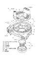
本実施形態のステアリングロールコネクタ10は、図1及至図6に示すように、ケーブルハウジング11と、リテーナ41と、回転ロック構成体51とで構成している。
ケーブルハウジング11は、平面視中央部分にステアリングの回転軸方向(図4中の上下方向)に貫通した差込孔Hが形成された略円筒状の形態で構成されている。差込孔Hは、前記ステアリングコラム(図示省略)から突出するステアリングシャフト(図示省略)の挿入を許容する径で形成されている。
なお、前記ステアリングシャフトの上端部には、回転操作を行うためのステアリングホイールが固定されている。
An embodiment of the present invention will be described below with reference to the drawings.
As shown in FIGS. 1 to 6, the
The
A steering wheel for performing a rotation operation is fixed to the upper end portion of the steering shaft.
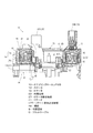
ケーブルハウジング11は、互いに相対回転可能なステータ12とロテータ13とで構成する概ね円筒状をしたケースである。ケーブルハウジング11の内部には、図3及至図5に示すように、フレキシブルフラットケーブルC(以下、「フラットケーブルC」という。)が適宜巻かれた状態で収容される収容空間Sが構成されている。
The
ステータ12は、車体側の適宜の部材、例えばステアリングコラムのコンビネーションブラケットスイッチ(図示省略)に固定され、ステアリングホイールに対して相対回転可能に取り付けられている。前記ステータ12は、底板として環状に形成した固定側リング板14と、この固定側リング板14の外周縁から垂直に延びる円筒状の外周筒部15とで構成されている。ステータ12は、固定側リング板14の外周縁と外周筒部15の下端とを嵌合することで一体に構成している。
The
外周筒部15は、図5に示すように、円筒状の外側外周筒部15oと、該外側外周筒部15oよりも僅かに小径である円筒状の内側外周筒部15iとで構成され、外側外周筒部15oと内側外周筒部15iとが半径方向において近接して対向するよう同心円状に配置した2層構造で構成されている。
As shown in FIG. 5, the outer peripheral
また、前記内側外周筒部15iの上部には、図5に示すように、収容空間Sで巻き回したフラットケーブルCよりも上方で該収容空間Sに向けて半径方向の内側(径内方向)へ突出し、該フラットケーブルCを上方からガイドするガイド突出片16が鍔状に形成されている。
Further, at the upper part of the inner outer
ステータ12には、ステータ側コネクタ17が取り付けられている。
ステータ側コネクタ17は、第1ステータ側コネクタ17Aと第2ステータ側コネクタ17Bとで構成している。第1ステータ側コネクタ17Aと第2ステータ側コネクタ17Bとは、所定間隔を隔ててそれぞれのコネクタ接続口が同じ方向を向くように外周筒部15(外側外周筒部15o)の外側に配置されている。
A
The
前記ロテータ13は、リング状に形成された天板としての回転側リング板21と、この回転側リング板21の内周縁から垂直に延びる円筒状の内周筒部22とで構成されている。
The
内周筒部22の下端周縁部には、図4、図5、及び、図7に示すように、リテーナ41の上面に当接するロテータ側当接部27を形成している。ロテータ側当接部27は、平坦な面状に形成されている。
As shown in FIGS. 4, 5, and 7, a rotator
そしてロテータ13は、ステアリングホイールとともに一体的に回転する構成である。詳しくは、ロテータ13は、ステータ12に対して前記ステアリングの回転軸と同一の軸回りに回転することができる。このときロテータ側当接部27は、リテーナ41の上面に当接しながら摺動する。
The
回転側リング板21は、ロテータ13の回転軸の方向で前記固定側リング板14に対面するように配置されている。
なお、ロテータ13の回転軸の方向は、上述したステアリングの回転軸方向(図4中の上下方向)と同じ方向である。
The rotation-
The direction of the rotation axis of the
また、前記内周筒部22は、外周筒部15に対して半径方向(図4中の左右方向)内側で対面するように配置されている。
Further, the inner peripheral
ロテータ13には、該ロテータ13の回転に伴って一体的に回転するロテータ側コネクタ23Bが取り付けられる。
ロテータ側コネクタ23は、第1ロテータ側コネクタ23Aと第2ロテータ側コネクタ23Bとで構成している。
A rotator-
The rotator-
第1ロテータ側コネクタ23Aと第1ステータ側コネクタ17A、及び、第2ロテータ側コネクタ23Bと第2ステータ側コネクタ17Bとは、それぞれ収容空間Sに配置されたフラットケーブルCによって相互に電気的に接続されている。
The first rotator-
ステータ側コネクタ17は、ロアコラムカバー(図示省略)内において車体側の電気回路等から引き出されたケーブル(図示省略)にそれぞれ接続される。
ロテータ側コネクタ23は、例えば、ホーンスイッチ、エアバッグユニットなどの電気回路から引き出されたケーブル(図示省略)にそれぞれ接続される。
The
The rotator-
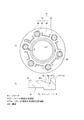
また、上述のリテーナ41は、図2及至図7に示すように、複数の回転ローラ43とベースリング42とで構成され、収容空間Sにおいてロテータ13の回転軸を中心にして回転可能に配置されている。
Further, as shown in FIGS. 2 to 7, the
回転ローラ43は、後述のローラ支持突部45と同じ数で備えられ、それぞれローラ支持突部45に軸支され、それぞれが前記ロテータ13の回転軸と平行な軸を中心として回転可能に設けられている。
The
ベースリング42は、平面視円環状をした板状のベースリング本体部44とローラ支持突部45とローラ外周側突部46とで構成されている。
ベースリング本体部44は、前記固定側リング板14に対して回転方向に摺動可能に載置され、ステータ12に対して相対回転可能に構成されている。ベースリング本体部44を前記固定側リング板14に載置したとき、ベースリング本体部44の内周縁部は、図6(a),(b)、及び、図7に示すように、収容空間Sの半径方向の内側Riにおいて前記固定側リング板14の内周縁部と内周筒部22のロテータ側当接部27との間に介在する。
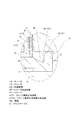
なお、図6(a)は,リテーナ41の平面図であり、図6(b)は、図6(a)中のB−B線拡大端面図である。
The
The base ring
6A is a plan view of the
ベースリング本体部44の上面の内周縁部には、図6(a),(b)、及び、図7に示すように、前記内周筒部22のロテータ側当接部27と対向するリテーナ側当接部47が形成されている。該リテーナ側当接部47は、前記ロテータ側当接部27に対して摺動可能に当接するよう上方へ向けて突出したリテーナ側突出当接部47Tで形成している。
As shown in FIGS. 6A, 6B, and 7, the retainer facing the rotator
ベースリング本体部44の上面のリテーナ側突出当接部47Tに対して半径方向の一回り外側Roには、周方向に沿って凹んだ溝部48が形成されている(図6(a),(b)参照)。溝部48は、リテーナ側突出当接部47Tの外周側基端部47Taが最深部48aとなり、該最深部48aから半径方向の外側Roへ向けて徐々に浅くなる傾斜面48bを有した溝形状で形成している(図6(b)参照)。
A
前記ローラ支持突部45は、ベースリング本体部44の周方向に等間隔ごとに回転ローラ43を軸支可能に上方に向けて突出している。
The
ローラ外周側突部46は、ローラ支持突部45に対して外側で、フラットケーブルCを後述するように回転ローラ43の周りに折り返した折り返し部分(後述する反転部分Cr)を径外側からガイドするようベースリング本体部44に対して上方に向けて突出している。
The roller outer
また、フラットケーブルCは、複数の扁平な平角導体Caが所定のピッチで平行に配列され、電気絶縁体Cbで被覆した可撓性を有する帯状の伝送線である(図9参照)。 Further, the flat cable C is a flexible band-shaped transmission line in which a plurality of flat rectangular conductors Ca are arranged in parallel at a predetermined pitch and covered with an electrical insulator Cb (see FIG. 9).
フラットケーブルCは、収容空間Sで2本備え、該収容空間Sにおいて2本を重ね合わせて巻き回した状態で備えている。重ね合わせた2本のうち一方のフラットケーブルCにおける長さ方向の一端側を第1ステータ側コネクタ17A側に接続しているとともに、2本のうち他方のフラットケーブルCにおける長さ方向の一端側を第2ステータ側コネクタ17B側に接続している。
Two flat cables C are provided in the accommodation space S, and are provided in a state in which the two are overlapped and wound in the accommodation space S. One end side in the length direction of one flat cable C of the two overlapped ones is connected to the first
重ね合わせた2本のうち一方のフラットケーブルCにおける長さ方向の他端側を第1ロテータ側コネクタ23A側に接続しているとともに、2本のうち他方のフラットケーブルCにおける長さ方向の他端側を第2ロテータ側コネクタ23B側に接続している。
The other end in the length direction of one flat cable C of the two overlapped ones is connected to the first
このようなフラットケーブルCは、ケーブルハウジング11の内部の収容空間Sにおいて固定側リング板14に対して回転自在に載置されたリテーナ41によって支持され、巻回した状態で収容されている。
Such a flat cable C is supported by a
詳しくは、フラットケーブルCは、収容空間Sにおいて、第1ステータ側コネクタ17A、第2ステータ側コネクタ17Bのそれぞれから前記収容空間Sへ引き込まれ、図3及至図5に示すように、リテーナ41の外側でステータ12の外周筒部15(内側外周筒部15i)の内周面に沿うように巻かれた外側巻き部分Coが構成される。
Specifically, the flat cable C is drawn into the housing space S from each of the first stator-
従って、外側巻き部分Coの基端は、ステータ側コネクタ17の位置において固定されている。
なお、フラットケーブルCは、収容空間Sにおいて上述したように2本一組として重ね合わせて巻き回されているが、図4、図5、図7及び図10では、簡略化して一本のみを巻き回した状態で図示している。
Accordingly, the base end of the outer winding portion Co is fixed at the position of the
As described above, the flat cable C is wound as a set of two in the accommodation space S. However, in FIGS. 4, 5, 7 and 10, only one is simplified. It is shown in a wound state.
そして、図3中の破線で示すように、フラットケーブルCは、長さ方向の途中で、複数の前記回転ローラ43のうち1つにU字型に巻き掛かるようにして向きを反転させた反転部分Crが構成される。
As shown by the broken line in FIG. 3, the flat cable C is a reversal in which the direction is reversed in the middle of the length direction so as to be wound around one of the plurality of
フラットケーブルCは、その後は、長さ方向の他端側をリテーナ41の内側でロテータ13の内周筒部22の外周面に沿うように巻かれた内側巻き部分Ciが構成される。フラットケーブルCは、最終的には収容空間Sから引き出されて第1ロテータ側コネクタ23A、第2ロテータ側コネクタ23B側に接続される。
Thereafter, the flat cable C includes an inner winding portion Ci that is wound on the other end side in the length direction so as to be along the outer peripheral surface of the inner peripheral
従って、内側巻き部分Ciの基端は、ロテータ側コネクタ23の位置において固定されている。
Therefore, the base end of the inner winding portion Ci is fixed at the position of the
このように、前記収容空間Sの内部においてフラットケーブルCは、ロテータ13がステータ12に対して回転することにより、外側巻き部分Coと内側巻き部分Ciとの間でそれぞれ巻き付けと巻き解きのいずれかが行われる。
このとき、フラットケーブルCは、外側巻き部分Coと内側巻き部分Ciとの間の巻き状態のバランスの変化に追従するように反転部分Crがリテーナ41とともに適宜回転する。これにより、ステアリングロールコネクタ10は、フラットケーブルCを収容空間S内で常に整列された巻き付け状態で保持することができるとともに、円滑なステアリングホイールの回転操作を可能としている。
As described above, the flat cable C is either wound or unwound between the outer winding portion Co and the inner winding portion Ci when the
At this time, in the flat cable C, the reversal portion Cr rotates appropriately with the
続いて上述の回転ロック構成体51について簡単に説明する。回転ロック構成体51は、図2に示すように、ロック体52とバネ受けスリーブ54と、該ロック体52および該バネ受けスリーブ54との間に介在する戻しバネ53とで構成されている。
Next, the
バネ受けスリーブ54を戻しバネ53の付勢力に抗して押し上げることでステータ12に対してロテータ13が相対回転しないようロック体52でロックすることができ、或いは、ステアリングホイールの芯金のボス部(図示省略)を挿入することで自由に相対回転することを許容するようロック体52によるロックを解除することができる。
By pushing up the
上述した構成のステアリングロールコネクタ10は、様々な作用、効果を得ることができるが、特に上述したように、リテーナ側当接部47を、リテーナ側突出当接部47Tで形成したため、以下のような作用、効果を得ることができる。
図7に示すように、リテーナ側突出当接部47Tは、ロテータ側当接部27に向けて突出しているため、リテーナ41の周方向全体に亘って該ロテータ側当接部27に対して半径方向Rにおいて点状に当接させることができる。
The
As shown in FIG. 7, the retainer-side protruding
これにより、従来のようにリテーナ41の内周縁部と内周筒部22の下縁部とを面状に接触させた構成と比較して接触面積を小さくすることができ、ステアリングホイールを回転操作したとき、リテーナ側当接部47とロテータ側当接部27との摺動抵抗を大幅に低減することができる。
Thereby, compared with the structure which made the inner peripheral part of the
よって、収容空間Sにおいて巻き回された状態のフラットケーブルCがステアリングホイールの回転操作に伴って収容空間Sの外周側と内周側との各側に対して巻き付けと巻き解きが行われた際にも、収容空間Sの底面においてフラットケーブルCを支持するリテーナ41は、このようなフラットケーブルCの動きに迅速に対応してステアリングの軸回りに滑らかに回転することができる。
Therefore, when the flat cable C wound in the accommodation space S is wound and unwound around each of the outer peripheral side and the inner peripheral side of the storage space S in accordance with the rotation operation of the steering wheel. In addition, the
従って、フラットケーブルCがリテーナ41から受ける荷重や接触抵抗を大幅に低減させることで磨耗するなどして損傷することを防ぐことができる。
Therefore, it is possible to prevent the flat cable C from being damaged due to wear or the like by greatly reducing the load and contact resistance received from the
詳しくは、ステアリングホイールの回転操作の際に、フラットケーブルCの外側巻き部分Coと内側巻き部分Ciとの間の巻き回し状態の変化に伴って、フラットケーブルCの反転部分Crは、U字型に巻き掛けた回転ローラ43に対して該回転ローラ43とローラ外周側突部46との間で弛緩する。
Specifically, when the steering wheel is rotated, the reverse portion Cr of the flat cable C is U-shaped as the winding state changes between the outer winding portion Co and the inner winding portion Ci of the flat cable C. The rotating
このとき、リテーナ41は、回転ローラ43とローラ外周側突部46が反転部分Crから荷重を受ける。これによりリテーナ41は、フラットケーブルCの外側巻き部分Coと内側巻き部分Ciとの間の巻き状態の変化に追従して回転することができる。
At this time, in the
このとき上述したようにリテーナ側当接部47を、リテーナ側突出当接部47Tで形成することにより、リテーナ41は、円滑に回転することができるため、フラットケーブルCの特に反転部分Crは、リテーナ41から受ける荷重を大幅に低減することができる。
At this time, by forming the retainer
従って、フラットケーブルCがリテーナ41から受ける荷重や接触抵抗を大幅に低減し磨耗するなどして損傷することを防ぐことができる。
Therefore, the load and contact resistance that the flat cable C receives from the
さらにまた、上述したようにリテーナ側当接部47を、リテーナ側突出当接部47Tで形成することにより、図8(a)に示すように、リテーナ側突出当接部47Tとロテータ側当接部27とは、これらの間にリテーナ41の内周縁全周に亘って隙間がなくしっかりと当接するため、粉塵が入り込もうとしても、その侵入を防ぐことができる(図8(a)中の矢印参照)。
Furthermore, by forming the retainer
また、リテーナ41のリテーナ側突出当接部47Tの下端部であって、該リテーナ側突出当接部47Tの半径方向の外側Roには、溝部48を形成しているため、図8(b)に示すように、万が一にも、リテーナ側突出当接部47Tとロテータ側当接部27との間を通じて外側から収容空間Sへ粉塵が入り込んだ場合でも(図8(b)中の仮想線で示した矢印参照)、粉塵Dを収容空間Sにおいて拡散しないよう該溝部48に留めておくことができる。
Further, since the
これにより、例えば、粉塵がリテーナ41の上面に付着するなどして、フラットケーブルCとリテーナ41との間に粉塵が介在することがないため、フラットケーブルCとリテーナ41との接触抵抗を抑えることができるとともに、フラットケーブルCとリテーナ41とが粉塵を介して擦れることで耳障りな音が発生することを未然に防ぐことができる。
Thereby, for example, since dust does not adhere between the flat cable C and the
特に、上述したように溝部48を、リテーナ側突出当接部47Tの基端部47Taが最深となる溝形状で形成したため、粉塵が万が一にもロテータ側当接部27とリテーナ側突出当接部47Tとの間を通じて収容空間Sに入り込んだ場合でも、粉塵が収容空間Sに入り込んだ直後に溝部48に留めておくことができる。
In particular, as described above, the
よって、粉塵が収容空間Sにおいて拡散することを、より確実に防ぐことができる。 Therefore, it is possible to more reliably prevent dust from diffusing in the accommodation space S.
さらに、溝部48を、最深部48aである基端部47Taからリテーナ41の半径方向の外側Roへ向けて徐々に浅くなる滑らかな溝形状で形成することにより、ステアリングホイールの回転操作に伴ってロテータ側当接部27とリテーナ側突出当接部47Tとが摺動している最中に、ロテータ側当接部27が溝部48に引っ掛かることがなく、ロテータ側当接部27とリテーナ側突出当接部47Tとを円滑に摺動させることができる。
Further, by forming the
同様に、溝部48を、上述したような滑らかな溝形状で形成しているため、図9に示すように、リテーナ41の上面内周部に支持されたフラットケーブルCの内側巻き部分Ciが溝部48に引っ掛かることがなく、内周筒部22の外周面に対する内側巻き部分Ciの円滑な巻き付けと巻き解きを行うことが可能となる。
Similarly, since the
従って、フラットケーブルCは、収容空間S内で常に整列された巻き回し状態でステアリングホイールの回転操作に対応した巻き付けと巻き解きのいずれかをスムーズに行うことができる。 Therefore, the flat cable C can smoothly perform either winding or unwinding corresponding to the rotation operation of the steering wheel in a winding state in which the flat cable C is always aligned in the accommodation space S.
なお、上述したように前記ロテータ側当接部27と前記リテーナ側当接部47は、上述した構成に限らず、該ロテータ側当接部27と該リテーナ側当接部47とのうち少なくとも一方の側を他方の側へ向けて突出した形状で形成することができる。
As described above, the rotator-
例えば、他の実施形態として、図10(a)に示すように、前記リテーナ側当接部47を前記ロテータ側当接部27側へ突出させずに形成し、前記ロテータ側当接部27を前記リテーナ側当接部47側に対して当接するよう突出させたロテータ側突出当接部27Tで形成することができる。
For example, as another embodiment, as shown in FIG. 10A, the retainer-
この構成の場合においても、リテーナ側当接部47とロテータ側当接部27とを面状に接触させる場合と比較して接触面積を小さくすることができ、ステアリングホイールを回転操作したとき、リテーナ側当接部47とロテータ側当接部27との摺動抵抗を大幅に低減することができる。
Even in this configuration, the contact area can be reduced as compared with the case where the retainer
さらに他の実施形態として、図10(b)に示すように、リテーナ側当接部47を上述したようなリテーナ側突出当接部47Tで形成し、前記ロテータ側当接部27を上述したようなロテータ側突出当接部27Tで形成してもよい。
As still another embodiment, as shown in FIG. 10B, the retainer
この構成の場合、前記リテーナ側突出当接部47Tと前記ロテータ側当接部27が当接することで、突状の先端部分同士が当接することとなり、リテーナ41の半径方向Rにおいて点状に当接するため、ステアリングホイールを回転操作したとき、リテーナ41の上面内周部と内周筒部の下部との摺動抵抗を大幅に低減することができる。
In this configuration, the retainer-side protruding
このように本発明は、上述した実施形態に限定せず、様々な実施形態で構成することができる。
なお、この発明の構成と、上述した実施形態との対応において、回転コネクタ装置は、ステアリングロールコネクタ10に対応し、ケーブルは、フラットケーブルCに対応するものとする。
Thus, the present invention is not limited to the above-described embodiments, and can be configured in various embodiments.
In the correspondence between the configuration of the present invention and the above-described embodiment, the rotation connector device corresponds to the
10…ステアリングロールコネクタ
12…ステータ
13…ロテータ
22…内周筒部
27…ロテータ側当接部
27T…ロテータ側突出当接部
41…リテーナ
47…リテーナ側当接部
47T…リテーナ側突出当接部
47Ta…リテーナ側突出当接部の基端部
48…溝部
S…収容空間
C…フラットケーブル
DESCRIPTION OF
Claims (1)
前記ステータと前記ロテータとの内部に、該ロテータ側と該ステータ側とを電気的に接続するケーブルを巻き回した状態で収容する平面視環状の収容空間を構成し、
上面側に配置したケーブルをステアリングと同心状に回転案内可能に前記収容空間の底面に配置するリテーナを備えた回転コネクタ装置であって、
前記ロテータに、前記収容空間の内周面を構成する内周筒部を備え、
前記内周筒部の下部に、前記リテーナの上面の内周部と摺動可能に当接するロテータ側当接部を構成し、
前記リテーナの上面内周部に、前記ロテータ側当接部と摺動可能に当接するリテーナ側当接部を構成し、
前記リテーナ側当接部に、前記ロテータ側当接部へ向けて上向きに突出したリテーナ側突出当接部を形成するとともに、
前記リテーナの前記リテーナ側当接部に対して半径方向の外側に、溝部を形成し、該溝部を、前記リテーナ側突出当接部の基端部が最深となり、該基端部から前記リテーナの半径方向の外側へ向けて徐々に浅くなる溝形状で形成した
回転コネクタ装置。 A stator and a rotator that rotates concentrically with the steering relative to the stator;
In the stator and the rotator, a ring-shaped accommodation space that is accommodated in a state in which a cable that electrically connects the rotator side and the stator side is wound is configured,
A rotary connector device comprising a retainer that arranges a cable arranged on the upper surface side on the bottom surface of the housing space so as to be able to rotate and guide concentrically with the steering wheel,
The rotator is provided with an inner peripheral cylindrical portion that constitutes an inner peripheral surface of the accommodation space,
A rotator-side contact portion that slidably contacts the inner peripheral portion of the upper surface of the retainer is formed at the lower portion of the inner peripheral cylindrical portion,
A retainer side contact portion that slidably contacts with the rotator side contact portion is formed on the inner periphery of the upper surface of the retainer,
In the retainer side contact portion, a retainer side protruding contact portion protruding upward toward the rotator side contact portion is formed , and
A groove portion is formed radially outward with respect to the retainer side contact portion of the retainer, and the groove portion has a deepest base end portion of the retainer side projecting contact portion, from the base end portion of the retainer. Groove shape that gradually becomes shallower toward the outside in the radial direction
Rotating connector device.
Priority Applications (5)
| Application Number | Priority Date | Filing Date | Title |
|---|---|---|---|
| JP2010078597A JP5117528B2 (en) | 2010-03-30 | 2010-03-30 | Rotating connector device |
| EP11762701.8A EP2555345B1 (en) | 2010-03-30 | 2011-03-25 | Rotary connector device |
| PCT/JP2011/057341 WO2011122470A1 (en) | 2010-03-30 | 2011-03-25 | Rotary connector device |
| CN201180016925.XA CN102823083B (en) | 2010-03-30 | 2011-03-25 | Rotary connector device |
| US13/632,669 US8758024B2 (en) | 2010-03-30 | 2012-10-01 | Rotary connector device |
Applications Claiming Priority (1)
| Application Number | Priority Date | Filing Date | Title |
|---|---|---|---|
| JP2010078597A JP5117528B2 (en) | 2010-03-30 | 2010-03-30 | Rotating connector device |
Publications (2)
| Publication Number | Publication Date |
|---|---|
| JP2011210616A JP2011210616A (en) | 2011-10-20 |
| JP5117528B2 true JP5117528B2 (en) | 2013-01-16 |
Family
ID=44712179
Family Applications (1)
| Application Number | Title | Priority Date | Filing Date |
|---|---|---|---|
| JP2010078597A Active JP5117528B2 (en) | 2010-03-30 | 2010-03-30 | Rotating connector device |
Country Status (5)
| Country | Link |
|---|---|
| US (1) | US8758024B2 (en) |
| EP (1) | EP2555345B1 (en) |
| JP (1) | JP5117528B2 (en) |
| CN (1) | CN102823083B (en) |
| WO (1) | WO2011122470A1 (en) |
Families Citing this family (14)
| Publication number | Priority date | Publication date | Assignee | Title |
|---|---|---|---|---|
| JP5224404B2 (en) * | 2010-03-30 | 2013-07-03 | 古河電気工業株式会社 | Rotating connector device |
| KR101550942B1 (en) | 2010-10-22 | 2015-09-08 | 현대자동차주식회사 | Female Connector Having Improved Unlocking Structure |
| JP6188682B2 (en) * | 2011-05-20 | 2017-08-30 | コーニンクレッカ フィリップス エヌ ヴェKoninklijke Philips N.V. | Rotary electrical connector and breathing gas supply system using this connector |
| JP5584667B2 (en) | 2011-09-27 | 2014-09-03 | 金井 宏彰 | Traverse device and traverse method |
| JP5624972B2 (en) * | 2011-10-31 | 2014-11-12 | 古河電気工業株式会社 | Rotating connector device |
| JP5584734B2 (en) | 2012-06-20 | 2014-09-03 | 金井 宏彰 | Traverse device and traverse method |
| US9553414B2 (en) * | 2013-07-04 | 2017-01-24 | Nissan Motor Co., Ltd. | Motor power feed wiring structure having a vehicle body-side power feed wire rotatably connected to a motor-side power feed wire |
| CN108473153B (en) * | 2016-02-22 | 2021-06-08 | 古河电气工业株式会社 | Steering column structure |
| US10647275B2 (en) * | 2016-03-31 | 2020-05-12 | Furukawa Electric Co., Ltd. | Rotary connector device |
| KR102132312B1 (en) * | 2016-03-31 | 2020-07-09 | 후루카와 덴키 고교 가부시키가이샤 | Swivel connector device |
| CN109075517B (en) * | 2016-05-31 | 2020-05-05 | 阿尔卑斯阿尔派株式会社 | Rotary connector |
| WO2019230563A1 (en) * | 2018-05-28 | 2019-12-05 | 古河電気工業株式会社 | Rotary connector device and rotary body of rotary connector device |
| JP7371010B2 (en) * | 2018-12-13 | 2023-10-30 | 古河電気工業株式会社 | rotating connector device |
| EP3930117A4 (en) * | 2019-02-21 | 2022-04-27 | Furukawa Electric Co., Ltd. | Rotary connector device |
Family Cites Families (24)
| Publication number | Priority date | Publication date | Assignee | Title |
|---|---|---|---|---|
| DE4446901C2 (en) * | 1993-12-27 | 2001-01-25 | Nihon Plast Co Ltd | Electrical clock spring connector |
| JP2921733B2 (en) * | 1994-08-26 | 1999-07-19 | 矢崎総業株式会社 | Electrical connection between steering wheel and steering column |
| GB9512741D0 (en) * | 1995-06-22 | 1995-08-23 | Lucas Ind Plc | Connector |
| JPH09274981A (en) * | 1995-08-11 | 1997-10-21 | Yazaki Corp | Relay device between relative rotation members |
| JP3153740B2 (en) * | 1995-08-11 | 2001-04-09 | 矢崎総業株式会社 | Electrical connection device between fixed body and rotating body |
| DE69622340T2 (en) * | 1995-10-27 | 2003-03-27 | Alps Electric Co Ltd | rotary connector |
| JPH1022026A (en) * | 1996-06-28 | 1998-01-23 | Yazaki Corp | Relay device for use between relative rotation members |
| JPH10154565A (en) * | 1996-11-22 | 1998-06-09 | Furukawa Electric Co Ltd:The | Rotary connector |
| JPH11209005A (en) * | 1998-01-21 | 1999-08-03 | Yazaki Corp | Cable reel |
| JP3676146B2 (en) * | 1999-10-22 | 2005-07-27 | 古河電気工業株式会社 | Rotating connector |
| JP2003059610A (en) * | 2001-08-22 | 2003-02-28 | Sumitomo Wiring Syst Ltd | Cable reel |
| JP4024025B2 (en) * | 2001-10-11 | 2007-12-19 | ナイルス株式会社 | Rotating connector device |
| FR2830989B1 (en) * | 2001-10-17 | 2004-06-11 | Valeo Electronique | ROTARY ELECTRIC SWITCH AND STEERING ASSEMBLY OF A MOTOR VEHICLE WITH THIS CONTACTOR |
| JP2003187941A (en) * | 2001-12-19 | 2003-07-04 | Alps Electric Co Ltd | Rotary connector |
| US7104821B2 (en) * | 2004-09-16 | 2006-09-12 | Alps Electric Co., Ltd. | Rotary connector |
| JP2006086044A (en) * | 2004-09-16 | 2006-03-30 | Alps Electric Co Ltd | Rotary connector |
| JP2006335318A (en) * | 2005-06-06 | 2006-12-14 | Alps Electric Co Ltd | Connection structure of rotary connector to steering angle sensor |
| JP4602176B2 (en) * | 2005-07-01 | 2010-12-22 | 矢崎総業株式会社 | Rotating connector device |
| JP2007220505A (en) * | 2006-02-17 | 2007-08-30 | Yazaki Corp | Rotating connector apparatus |
| JP2008021555A (en) * | 2006-07-13 | 2008-01-31 | Alps Electric Co Ltd | Rotating connector |
| JP2009080958A (en) * | 2007-09-25 | 2009-04-16 | Alps Electric Co Ltd | Rotating connector |
| JP4491013B2 (en) * | 2007-12-17 | 2010-06-30 | アルプス電気株式会社 | Rotating connector |
| JP2009205915A (en) * | 2008-02-27 | 2009-09-10 | Alps Electric Co Ltd | Rotating connector |
| JP5271752B2 (en) * | 2009-02-25 | 2013-08-21 | アルプス電気株式会社 | Rotating connector mounting structure |
-
2010
- 2010-03-30 JP JP2010078597A patent/JP5117528B2/en active Active
-
2011
- 2011-03-25 CN CN201180016925.XA patent/CN102823083B/en not_active Expired - Fee Related
- 2011-03-25 EP EP11762701.8A patent/EP2555345B1/en not_active Not-in-force
- 2011-03-25 WO PCT/JP2011/057341 patent/WO2011122470A1/en active Application Filing
-
2012
- 2012-10-01 US US13/632,669 patent/US8758024B2/en active Active
Also Published As
| Publication number | Publication date |
|---|---|
| CN102823083A (en) | 2012-12-12 |
| CN102823083B (en) | 2015-06-03 |
| EP2555345A1 (en) | 2013-02-06 |
| WO2011122470A1 (en) | 2011-10-06 |
| US8758024B2 (en) | 2014-06-24 |
| EP2555345A4 (en) | 2013-09-18 |
| US20130095670A1 (en) | 2013-04-18 |
| JP2011210616A (en) | 2011-10-20 |
| EP2555345B1 (en) | 2018-12-26 |
Similar Documents
| Publication | Publication Date | Title |
|---|---|---|
| JP5117528B2 (en) | Rotating connector device | |
| JP5041447B2 (en) | Rotating connector device | |
| JP5117595B2 (en) | Rotating connector device | |
| JP5065508B2 (en) | Rotating connector device | |
| JP5184716B2 (en) | Rotating connector device | |
| JP5654025B2 (en) | Rotating connector device | |
| US9070496B2 (en) | Rotatable connector device | |
| JP2011207402A5 (en) | ||
| JP2011258546A5 (en) | ||
| JP2011228287A5 (en) | ||
| EP2597734B1 (en) | Rotary connector device | |
| JP5224404B2 (en) | Rotating connector device | |
| JP5041449B2 (en) | Rotating connector device | |
| JP5624972B2 (en) | Rotating connector device | |
| JP2010129285A (en) | Rotary connector device | |
| EP2693577B1 (en) | Rotatable connector device |
Legal Events
| Date | Code | Title | Description |
|---|---|---|---|
| A621 | Written request for application examination |
Free format text: JAPANESE INTERMEDIATE CODE: A621 Effective date: 20111003 |
|
| A871 | Explanation of circumstances concerning accelerated examination |
Free format text: JAPANESE INTERMEDIATE CODE: A871 Effective date: 20120523 |
|
| A975 | Report on accelerated examination |
Free format text: JAPANESE INTERMEDIATE CODE: A971005 Effective date: 20120607 |
|
| A131 | Notification of reasons for refusal |
Free format text: JAPANESE INTERMEDIATE CODE: A131 Effective date: 20120619 |
|
| A521 | Request for written amendment filed |
Free format text: JAPANESE INTERMEDIATE CODE: A523 Effective date: 20120810 |
|
| TRDD | Decision of grant or rejection written | ||
| A01 | Written decision to grant a patent or to grant a registration (utility model) |
Free format text: JAPANESE INTERMEDIATE CODE: A01 Effective date: 20120918 |
|
| A01 | Written decision to grant a patent or to grant a registration (utility model) |
Free format text: JAPANESE INTERMEDIATE CODE: A01 |
|
| A61 | First payment of annual fees (during grant procedure) |
Free format text: JAPANESE INTERMEDIATE CODE: A61 Effective date: 20121017 |
|
| R151 | Written notification of patent or utility model registration |
Ref document number: 5117528 Country of ref document: JP Free format text: JAPANESE INTERMEDIATE CODE: R151 |
|
| FPAY | Renewal fee payment (event date is renewal date of database) |
Free format text: PAYMENT UNTIL: 20151026 Year of fee payment: 3 |
|
| S531 | Written request for registration of change of domicile |
Free format text: JAPANESE INTERMEDIATE CODE: R313531 |
|
| R350 | Written notification of registration of transfer |
Free format text: JAPANESE INTERMEDIATE CODE: R350 |