WO2011122467A1 - スライド式携帯電子機器 - Google Patents
スライド式携帯電子機器 Download PDFInfo
- Publication number
- WO2011122467A1 WO2011122467A1 PCT/JP2011/057327 JP2011057327W WO2011122467A1 WO 2011122467 A1 WO2011122467 A1 WO 2011122467A1 JP 2011057327 W JP2011057327 W JP 2011057327W WO 2011122467 A1 WO2011122467 A1 WO 2011122467A1
- Authority
- WO
- WIPO (PCT)
- Prior art keywords
- cabinet
- circuit board
- flexible lead
- case half
- electronic device
- Prior art date
Links
Images

Classifications
-
- H—ELECTRICITY
- H04—ELECTRIC COMMUNICATION TECHNIQUE
- H04M—TELEPHONIC COMMUNICATION
- H04M1/00—Substation equipment, e.g. for use by subscribers
- H04M1/02—Constructional features of telephone sets
- H04M1/0202—Portable telephone sets, e.g. cordless phones, mobile phones or bar type handsets
- H04M1/0206—Portable telephones comprising a plurality of mechanically joined movable body parts, e.g. hinged housings
- H04M1/0208—Portable telephones comprising a plurality of mechanically joined movable body parts, e.g. hinged housings characterized by the relative motions of the body parts
- H04M1/0235—Slidable or telescopic telephones, i.e. with a relative translation movement of the body parts; Telephones using a combination of translation and other relative motions of the body parts
- H04M1/0237—Sliding mechanism with one degree of freedom
-
- H—ELECTRICITY
- H04—ELECTRIC COMMUNICATION TECHNIQUE
- H04M—TELEPHONIC COMMUNICATION
- H04M1/00—Substation equipment, e.g. for use by subscribers
- H04M1/02—Constructional features of telephone sets
- H04M1/0202—Portable telephone sets, e.g. cordless phones, mobile phones or bar type handsets
- H04M1/026—Details of the structure or mounting of specific components
- H04M1/0274—Details of the structure or mounting of specific components for an electrical connector module
-
- G—PHYSICS
- G06—COMPUTING; CALCULATING OR COUNTING
- G06F—ELECTRIC DIGITAL DATA PROCESSING
- G06F1/00—Details not covered by groups G06F3/00 - G06F13/00 and G06F21/00
- G06F1/16—Constructional details or arrangements
- G06F1/1613—Constructional details or arrangements for portable computers
- G06F1/1615—Constructional details or arrangements for portable computers with several enclosures having relative motions, each enclosure supporting at least one I/O or computing function
- G06F1/1624—Constructional details or arrangements for portable computers with several enclosures having relative motions, each enclosure supporting at least one I/O or computing function with sliding enclosures, e.g. sliding keyboard or display
-
- G—PHYSICS
- G06—COMPUTING; CALCULATING OR COUNTING
- G06F—ELECTRIC DIGITAL DATA PROCESSING
- G06F1/00—Details not covered by groups G06F3/00 - G06F13/00 and G06F21/00
- G06F1/16—Constructional details or arrangements
- G06F1/1613—Constructional details or arrangements for portable computers
- G06F1/1633—Constructional details or arrangements of portable computers not specific to the type of enclosures covered by groups G06F1/1615 - G06F1/1626
- G06F1/1675—Miscellaneous details related to the relative movement between the different enclosures or enclosure parts
- G06F1/1683—Miscellaneous details related to the relative movement between the different enclosures or enclosure parts for the transmission of signal or power between the different housings, e.g. details of wired or wireless communication, passage of cabling
-
- H—ELECTRICITY
- H02—GENERATION; CONVERSION OR DISTRIBUTION OF ELECTRIC POWER
- H02G—INSTALLATION OF ELECTRIC CABLES OR LINES, OR OF COMBINED OPTICAL AND ELECTRIC CABLES OR LINES
- H02G11/00—Arrangements of electric cables or lines between relatively-movable parts
Definitions
- the present invention relates to a slide-type portable electronic device configured by slidably connecting two cabinets such as a slide-type mobile phone.
- the slide type mobile phone includes a device main body configured such that the first cabinet and the second cabinet are slidably connected to each other, and an operation unit including a plurality of operation keys is installed on the surface of the first cabinet. And the display part comprised by the liquid crystal display panel is installed in the surface of the 2nd cabinet (for example, refer patent document 1).
- the main body of the device is operated by moving the first cabinet and the second cabinet relative to each other in the sliding direction so that both the cabinets are closed and at least a part of the operation part is covered with the second cabinet, and both cabinets are opened and operated. It is possible to change the state between the open state where the entire part is exposed.
- a flexible lead is connected to an electrical component such as a liquid crystal display panel mounted on the second cabinet, and the flexible lead is pulled out from the back surface of the second cabinet, and then the second lead. It passes through an opening provided on the surface of one cabinet and is connected to a circuit board built in the first cabinet (see, for example, Patent Document 2).
- the first cabinet is configured by joining together a front side case half forming the surface of the first cabinet and a back side case half forming the back of the first cabinet.
- the front-side case half is provided with an opening through which the flexible lead passes, and the circuit board is installed in the back-side case half.
- the flexible lead drawn out from the back surface of the second cabinet is passed through the opening of the front case half, and then the tip of the flexible lead is placed on the circuit board. Connect to the connector. Thereafter, the front side case half and the back side case half are joined together to form a first cabinet.
- the length of the flexible lead is the shortest length required for the flexible lead in the assembled state. Is set larger than. Therefore, in an assembled state, an extra portion (hereinafter referred to as an excess portion) is generated in the flexible lead.
- the surplus portion of the flexible lead is accommodated in the first cabinet, and as a result, a part of the surface of the circuit board is covered with the surplus portion. For this reason, an electronic component could not be mounted in the area covered by the flexible lead in the surface of the circuit board.
- An object of the present invention is to provide a slide-type portable electronic device that can be easily assembled and can reduce restrictions on circuit design.
- the sliding portable electronic device is A first cabinet containing a circuit board; A second cabinet slidably coupled to the first cabinet and carrying electrical components; Flexible leads drawn from the electrical components and connected to the circuit board through openings provided in the first cabinet; In a portable electronic device having The flexible lead has an overlapping portion that is partially folded on a predetermined region provided on the surface of the circuit board.
- the length of the flexible lead is the shortest necessary for the flexible lead in the assembled state. It is set larger than the length dimension. Therefore, in the assembled state, an excess portion is generated in the flexible lead.
- the surplus portion of the flexible lead is accommodated in the first cabinet, and as a result, a part of the surface of the circuit board is covered with the surplus portion.
- the surplus portion of the flexible lead is folded on a predetermined area provided on the surface of the circuit board, thereby superimposing the surplus portion on the predetermined area on the flexible lead. A part will be formed.
- the length dimension of the surplus portion of the flexible lead is increased, the area covered by the flexible lead on the surface of the circuit board can be prevented from expanding from the predetermined area to the outside. Therefore, the mounting area of the electronic component on the circuit board is not narrowed, and as a result, restrictions on circuit design can be reduced. In addition, by increasing the length of the surplus portion of the flexible lead, it becomes easy to assemble the slide-type portable electronic device.
- the slide portable electronic device according to the present invention is easy to assemble and can reduce restrictions on circuit design.
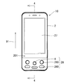
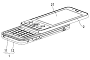
- FIG. 1 is a front view showing a slide type mobile phone according to an embodiment of the present invention.
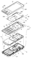
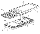
- FIG. 2 is an exploded perspective view of the slide type mobile phone.
- FIG. 3 is a front view used for explaining the closed state of the device body of the slide type mobile phone.
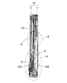
- FIG. 4 is a cross-sectional view taken along line 4-4 shown in FIG.
- FIG. 5 is an enlarged view of a region A shown in FIG.
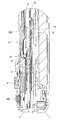
- FIG. 6 is an enlarged view of region B shown in FIG.
- FIG. 7 is a perspective view used for explaining the first step of the assembling procedure of the slide type mobile phone.
- FIG. 8 is a perspective view used for explaining the second step of the assembly procedure.
- FIG. 9 is an enlarged view of region C shown in FIG.
- FIG. 10 is a perspective view used for explaining the third step of the assembly procedure.
- FIG. 11 is a perspective view used for explaining the fourth step of the assembly procedure.
- FIG. 1 is a front view showing a slide type mobile phone according to an embodiment of the present invention.
- the slide-type mobile phone includes a device body (10) configured by slidably connecting a first cabinet (1) and a second cabinet (2).
- the first operation section (18) composed of a plurality of operation keys (180) to (180) is installed on the surface (101) of the first cabinet (1).
- a display unit constituted by a liquid crystal display panel (27) is installed, and a lever switch is provided in an area different from the installation area of the liquid crystal display panel (27).
- a second operation unit (28) composed of (4) and a plurality of operation keys (280) to (280) is provided.
- the lever switch (4) can be operated by a lever that slides the lever switch in four directions (up, down, left, and right) and four diagonal directions, and a lever operation that pushes the lever switch (2) toward the second cabinet (2).
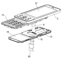
- FIG. 2 is an exploded perspective view of the slide type mobile phone.
- a flexible lead (6) described later is not shown.
- a slide mechanism (3) is provided between the first cabinet (1) and the second cabinet (2) so as to be slidable.
- the slide mechanism (3) A slide body (31) and a slide defining portion (32) are included.
- the slide body (31) has an opposing surface on the second cabinet (2) side among the opposing surfaces of the first cabinet (1) and the second cabinet (2) (that is, the rear surface (202 of the second cabinet (2)). )).
- the slide defining portion (32) is a facing surface on the first cabinet (1) side (that is, the first cabinet (1)) among the facing surfaces of the first cabinet (1) and the second cabinet (2).
- the surface (101)) specifically, is fixed to an area different from the installation area of the first operating portion (18).
- the slide defining portion (32) is formed with a pair of left and right guide grooves (320) and (320) at both end positions, and the pair of guide grooves (320) and (320) has a slide body (31).
- the left and right edges (310) (310) are slidably engaged.
- the slide direction (90) of the slide body (31) is defined by the slide defining portion (32) in the longitudinal direction (91) of the first cabinet (1), and therefore the second cabinet (2). Can move relative to the first cabinet (1) along its longitudinal direction (91).
- the device body (10) of the slide type mobile phone moves both the first cabinet (1) and the second cabinet (2) as shown in FIG. 3 by moving the first cabinet (1) relative to the second cabinet (2). Is closed and the first operation section 18 is entirely covered with the second cabinet 2 and the two cabinets 1 and 2 are opened as shown in FIG. 1 and the first operation section 18 is opened. It is possible to change the state between the open state in which the whole is exposed. Further, as shown in FIG. 2, the surface (101) of the first cabinet (1) has the second cabinet (10) regardless of whether the device body (10) is set to the closed state or the open state. The covering region R to be covered by 2) is provided.
- the user of the slide type mobile phone uses the first operation unit (18) and the second operation unit (28) to slide. It is possible to operate a mobile phone. Further, even when the device main body (10) is set in the closed state as shown in FIG. 3, the user can operate the sliding mobile phone using the second operation unit (28). is there.
- an opening (111) is provided in a part of the covering region R in the surface (101) of the first cabinet (1).
- a flexible lead (6) described later (see FIG. 6) passes through the opening (111).
- the first cabinet (1) has a built-in circuit board (5), and the circuit board (5) has a shape that extends widely along the surface (101) of the first cabinet (1). Yes. Accordingly, at least the installation area of the first operation section 18 and the covering area R overlap the circuit board 5 in the surface 101 of the first cabinet 1.
- the first cabinet (1) includes a front case half (11) that forms the surface (101) of the first cabinet (1), and a back surface (102) of the first cabinet (1). And a back side case half (12) that forms a structure.
- An opening (111) of the first cabinet (1) is provided in the front side case half (11), while a circuit board (5) is provided in the back side case half (12).
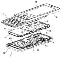
- the joint surface of the rear case half (12) surrounds the installation area of the circuit board (5).
- An annular groove (121) extending in the direction is formed.
- the seal member (14) extends from the region between the joining surfaces of the front-side case half (11) and the back-side case half (12) to the inside of the first cabinet (1), thereby providing a circuit board.
- the entire region not covered by the metal plate (13) is covered.
- the metal plate (13) and the seal member (14) are integrally formed without providing a gap therebetween.
- the seal member (14) is provided with a seal portion (142) to be fitted into the annular groove (121) of the rear case half (12) projecting toward the annular groove (121).
- the seal portion (142) of the seal member (14) is fitted into the annular groove (121) of the back case half (12), and the front case half (11) and the back side case half (12) are joined to each other, whereby the seal portion (142) is pressed into the annular groove (121) by the joining surface of the front side case half (11). become.
- the seal portion (142) of the seal member (14) is fitted into the annular groove (121) without any gap.
- a recess (131) is formed in a region different from the region exposed in the opening (111) of the first cabinet (1) in the assembled state of the first cabinet (1). And an opening (132) is provided at the bottom of the recess (131). Further, a waterproof sheet (15) that closes the opening (132) provided in the bottom is attached and fixed to the bottom of the recess (131), whereby the waterproof sheet (15) is attached to the bottom of the recess (131). Will be joined. As will be described later (see FIG. 6), the flexible lead (6) that has passed through the opening (111) of the first cabinet (1) passes between the bottom surface of the recess (131) and the waterproof sheet (15). After that, it passes through the opening (132) provided at the bottom of the recess (131).
- a part of the front case half (11) of the first cabinet (1) is bent and deformed to be raised toward the inner surface, thereby facing the recess (131) of the metal plate (13).
- a raised portion (112) is formed at the top.
- a recess (113) is formed in the surface (101) of the front side case half (11) by bending and deforming a part of the front side case half (11).
- the raised portion (112) of the front-side case half (11) is fitted into the recess (131) of the metal plate (13).
- the waterproof sheet (15 ) Is sandwiched between the raised portion (112) and the bottom of the concave portion (131). Therefore, even when water enters from the outside into the opening (111) of the front case half (11), it is waterproof that the water passes through the opening (132) provided at the bottom of the recess (131). It will be suppressed by the sheet (15).
- the intrusion of water from between the joining surfaces of the front case half (11) and the rear case half (12) is caused by the seal member (14). Will be suppressed. Furthermore, even when water enters the first cabinet (1) from the surface (101) side of the first cabinet (1), it is integrally formed that the water reaches the circuit board (5). It is suppressed by the metal plate (13) and the seal member (14). Accordingly, the metal plate (13) and the seal member (14) function as a waterproof member that covers the circuit board (5).
- the sliding cellular phone is provided with a waterproof structure for waterproofing the circuit board (5).
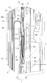
- FIG. 4 is a cross-sectional view taken along line 4-4 shown in FIG.
- FIG. 5 is an enlarged view of a region A shown in FIG.
- the flexible lead (6) is drawn out from the back surface (202) of the second cabinet (2), and the base end (61) of the flexible lead (6) is connected to the first cabinet ( It is connected to the circuit board (71) built in 1).
- Electronic components such as a lever switch (4) are mounted on the circuit board (71), and a liquid crystal display panel (27) is electrically connected through a second flexible lead (72).
- the base end portion (61) of the flexible lead (6) is electrically connected to the electrical components such as the liquid crystal display panel (27) and the lever switch (4) mounted on the second cabinet (2).
- the flexible lead (6) is drawn from the electrical components mounted on the second cabinet (2).
- FIG. 6 is an enlarged view of region B shown in FIG.
- the flexible lead (6) pulled out from the back surface (202) of the second cabinet (2) extends along the back surface (202) of the second cabinet (2), and then the first cabinet. It passes through an opening (111) provided in the front case half (11) of (1) and is connected to the circuit board (5) in the first cabinet (1).
- the flexible lead (6) pulled out from the back surface (202) of the second cabinet (2) extends upward along the back surface (202) of the second cabinet (2) and is then U-shaped. Is curved to pass through the opening (111) of the front case half (11), and then extends downward along the surface of the metal plate (13).
- the flexible lead (6) extending downward along the surface of the metal plate (13) passes between the bottom surface of the recess (131) and the joining surface of the waterproof sheet (15), and then the recess (131). It passes through an opening (132) provided at the bottom of the.
- a connector (51) is installed on the surface (50) of the circuit board (5) (see also FIG. 2), and the tip (62) of the flexible lead (6) is connected to the surface (50) of the circuit board (5). ) Is connected to the connector (51) from the direction along.
- the flexible lead (6) is formed by folding a part of the flexible lead (6) on a predetermined region F provided on the surface (50) of the circuit board (5).
- a superimposed portion (63) is formed in which the portion is superimposed on the predetermined region F.
- the predetermined area F is provided adjacent to the installation area of the connector (51) in the surface (50) of the circuit board (5) (see also FIG. 2).
- the flexible lead (6) has three bent portions (64) to (64) formed by folding a part of the flexible lead (6) at three locations, and the three bent portions ( The superimposing portion (63) is composed of 64) to (64).
- the three bent portions (64) to (64) are shifted from each other on the predetermined region F.
- FIG. 7 is a perspective view used for explaining the first step of the assembly procedure.
- the front case half (11) and the second cabinet (2) of the first cabinet (1) are connected to the slide mechanism (3 ) Are slidably connected to each other.
- the flexible lead (6) pulled out from the back surface (202) of the second cabinet (2) is passed through the opening (111) of the front case half (11).
- the flexible lead (6) is further passed through the opening (132) provided in the bottom of the recess (131) of the metal plate (13), and in that state, the waterproof sheet ( The opening (132) is closed by applying the step 15).
- the flexible lead (6) passes between the joint surface between the bottom of the recess (131) and the waterproof sheet (15) and is fixed to the metal plate (13) in that state.
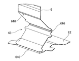
- FIG. 8 is a perspective view used for explaining the second step of the assembly procedure.
- a part of the flexible lead (6) Is folded on a predetermined region F provided on the surface (50) of the circuit board (5), thereby forming an overlapping portion (63) of the flexible lead (6).
- FIG. 9 is an enlarged view of region C shown in FIG. As shown in FIG. 9, the flexible lead (6) has a crease (6) at a position where the flexible lead (6) is folded and bent in order to facilitate its folding on the predetermined region F. 640).
- FIG. 10 is a perspective view used for explaining the third step of the assembly procedure.
- the back side case half (12) of the first cabinet (1) is integrally formed with the metal plate (13).
- the seal member (14) By attaching the seal member (14), the surface (50) of the circuit board (5) is covered with the metal plate (13) and the seal member (14).
- the seal portion (142) of the seal member (14) is fitted into the annular groove (121) of the back case half (12).
- FIG. 11 is a perspective view used for explaining the fourth step of the assembly procedure.
- the first cabinet (1) is joined by joining the front case half (11) and the back case half (12) of the first cabinet (1) together.
- the seal portion (142) of the seal member (14) is pressed into the annular groove (121) by the joining surface of the front-side case half (11), and as a result, the seal portion (142) is 121) will fit in the gap.
- the raised portion (112) of the front-side case half (11) is fitted into the recessed portion (131) of the metal plate (13), and as a result, the waterproof sheet (15) is formed between the raised portion (112) and the recessed portion. It will be pinched by the bottom of (131).
- the flexible lead (6) is fixed to the metal plate (13) in a state where it passes between the joint surface between the bottom of the recess (131) and the waterproof sheet (15), and The tip end portion (62) is connected and fixed to the connector (51). Therefore, the shape of the portion of the flexible lead (6) extending from the metal plate (13) to the connector (51) does not change even when the sliding operation of the sliding mobile phone is executed. That is, once the shape of the overlapping portion (63) of the flexible lead (6) is determined by completing the slide type mobile phone, the shape of the overlapping portion (63) does not change thereafter. Therefore, although the flexible lead (6) is bent at the overlapping portion (63) as described above, the wiring formed on the flexible lead (6) can be hardly cut.
- the length of the flexible lead (6) is set to facilitate the assembly of the slide type mobile phone such as connection of the flexible lead (6) to the connector (51) on the circuit board (5). Is set larger than the shortest length dimension required for the flexible lead (6) in the assembled state. Therefore, in the assembled state, an excessive portion is generated in the flexible lead (6).
- the first cabinet (1) is provided in addition to the connection of the flexible lead (6) to the connector (51) on the circuit board (5).
- the seal member (14) to the rear case half (12) it is necessary to set the length of the flexible lead (6) to be larger than that of a sliding mobile phone without a waterproof structure. is there.
- the surplus portion of the flexible lead (6) is folded on the predetermined area F provided on the surface (50) of the circuit board (5), whereby the flexible lead (6).
- an overlapping portion (63) in which the surplus portion is superimposed on the predetermined region F is formed.
- the length dimension of the surplus portion of the flexible lead (6) is increased, the area covered by the flexible lead (6) in the surface (50) of the circuit board (5) is outward from the predetermined area F. Expansion can be suppressed. Therefore, the mounting area of the electronic component on the circuit board (5) is not narrowed, and as a result, restrictions on circuit design can be reduced. In addition, by increasing the length of the surplus portion of the flexible lead (6), it becomes easy to assemble the slide-type mobile phone.
- a plurality of bent portions (64) formed on the flexible lead (6) in the assembled state are arranged on the predetermined region F so as to be shifted from each other. Therefore, it can suppress that the bending part (64) mutually presses. Therefore, even when a plurality of bent portions (64) are formed on the flexible lead (6), the wiring formed on the flexible lead (6) can be hardly cut.
- the tip (62) of the flexible lead (6) is connected to the connector (51) from the direction along the surface (50) of the circuit board (5). Accordingly, the thickness of the first cabinet (1) is larger than that of the configuration in which the tip (62) of the flexible lead (6) is connected to the connector (51) from the direction perpendicular to the surface (50) of the circuit board (5). The dimensions can be reduced.
- the flexible lead 6 it is necessary to connect the flexible lead 6 to the connector 51 so that the distal end 62 of the flexible lead 6 is connected.
- the length of the flexible lead (6) is larger than that of the configuration in which the connector (51) is connected from the direction perpendicular to the surface (50) of the circuit board (5). Nevertheless, according to the slide type mobile phone, for the same reason as described above, the mounting area of the electronic component on the circuit board (5) is not narrowed, thereby reducing the restrictions on the circuit design. can do.
- each part of the present invention is not limited to the above embodiment, and various modifications can be made within the technical scope described in the claims.
- one or two bent portions (64) are formed by folding a part of the flexible lead (6) at one or two places, and the one or two bent portions (64).
- the superimposing unit (63) may be configured.
- the flexible lead (6) has a plurality of bent portions (64) formed by folding a part of the flexible lead (6) at three or more locations, and the plurality of bent portions (64) are overlapped portions. (63) may be configured.
- the method of shifting the plurality of bent portions (64) on the predetermined region F is not limited to the form shown in FIG.
- the various configurations employed in the above-described sliding mobile phone can be applied to various sliding mobile electronic devices such as PDA (Personal Digital Assistant).
- adopted as the said flexible lead (6) is applicable also to the flexible lead provided in the slide-type portable electronic device without a waterproof structure.
Landscapes
- Engineering & Computer Science (AREA)
- Signal Processing (AREA)
- Telephone Set Structure (AREA)
Abstract
組み立てが容易であって且つ回路設計に関する制約を低減することのできるスライド式携帯電子機器を提供する。 本発明に係るスライド式携帯電子機器は、回路基板を内蔵する第1キャビネット1と、該第1キャビネットと互いにスライド可能に連結され、電気的構成要素を搭載する第2キャビネット2と、前記電気的構成要素から引き出され、第1キャビネットに設けられた開口を通過して前記回路基板5に接続されるフレキシブルリード6と、を有する携帯電子機器において、前記フレキシブルリードは、前記回路基板の表面に設けられた所定領域F上で一部が折り畳まれた重畳部63を有する。
Description
本発明は、スライド式携帯電話機等、2つのキャビネットを互いにスライド可能に連結して構成されたスライド式携帯電子機器に関する。
スライド式携帯電話機は、第1キャビネットと第2キャビネットとを互いにスライド可能に連結して構成された機器本体を具え、第1キャビネットの表面には、複数の操作キーによって構成された操作部が設置され、第2キャビネットの表面には、液晶表示パネルによって構成された表示部が設置されている(例えば、特許文献1参照)。機器本体は、第1キャビネットと第2キャビネットをスライド方向に相対移動させることにより、両キャビネットが閉じて操作部の少なくとも一部が第2キャビネットによって被覆された閉じ状態と、両キャビネットが開いて操作部の全体が露出した開き状態との間で状態を変更させることが可能である。
上記スライド式携帯電話機において、第2キャビネットに搭載された液晶表示パネル等の電気的構成要素にはフレキシブルリードが接続されており、該フレキシブルリードは、第2キャビネットの背面から引き出され、その後、第1キャビネットの表面に設けられた開口を通過して、該第1キャビネットに内蔵されている回路基板に接続されている(例えば、特許文献2参照)。
具体的には、第1キャビネットは、該第1キャビネットの表面を形成する表面側ケース半体と、該第1キャビネットの背面を形成する背面側ケース半体とを互いに接合して構成されており、表面側ケース半体に、フレキシブルリードが通過する開口が設けられ、背面側ケース半体に回路基板が設置されている。
そして、スライド式携帯電話機の組み立て工程においては、先ず表面側ケース半体の開口に、第2キャビネットの背面から引き出されたフレキシブルリードを通過させ、次に、フレキシブルリードの先端部を回路基板上のコネクタに接続する。その後、表面側ケース半体と背面側ケース半体とを互いに接合して第1キャビネットを形成する。
ここで、回路基板上のコネクタへのフレキシブルリードの接続等、スライド式携帯電話機の組み立てを容易にするべく、フレキシブルリードの長さ寸法は、組み立て状態において該フレキシブルリードに必要な最短の長さ寸法よりも大きく設定されている。従って、組み立て状態においては、フレキシブルリードに余分な部分(以下、余剰部分という)が生じることになる。フレキシブルリードの余剰部分は第1キャビネット内に収容され、その結果、該余剰部分によって回路基板の表面の一部が覆われることになる。このため、回路基板の表面の内、フレキシブルリードによって覆われた領域には、電子部品を搭載することが出来なかった。
本発明の目的は、組み立てが容易であって且つ回路設計に関する制約を低減することのできるスライド式携帯電子機器を提供することである。
本発明に係るスライド式携帯電子機器は、
回路基板を内蔵する第1キャビネットと、
該第1キャビネットと互いにスライド可能に連結され、電気的構成要素を搭載する第2キャビネットと、
前記電気的構成要素から引き出され、第1キャビネットに設けられた開口を通過して前記回路基板に接続されるフレキシブルリードと、
を有する携帯電子機器において、
前記フレキシブルリードは、前記回路基板の表面に設けられた所定領域上で一部が折り畳まれた重畳部を有している。
回路基板を内蔵する第1キャビネットと、
該第1キャビネットと互いにスライド可能に連結され、電気的構成要素を搭載する第2キャビネットと、
前記電気的構成要素から引き出され、第1キャビネットに設けられた開口を通過して前記回路基板に接続されるフレキシブルリードと、
を有する携帯電子機器において、
前記フレキシブルリードは、前記回路基板の表面に設けられた所定領域上で一部が折り畳まれた重畳部を有している。
上記スライド式携帯電子機器において、回路基板へのフレキシブルリードの接続等、スライド式携帯電子機器の組み立てを容易にするべく、フレキシブルリードの長さ寸法は、組み立て状態において該フレキシブルリードに必要な最短の長さ寸法よりも大きく設定されている。従って、組み立て状態においては、フレキシブルリードに余剰部分が生じることになる。フレキシブルリードの余剰部分は第1キャビネット内に収容され、その結果、該余剰部分によって回路基板の表面の一部が覆われることになる。
上記スライド式携帯電子機器においては、フレキシブルリードの余剰部分が、回路基板の表面に設けられた所定領域上にて折り畳まれ、これにより、フレキシブルリードに、その余剰部分が所定領域上に重畳した重畳部が形成されることになる。
従って、フレキシブルリードの余剰部分の長さ寸法が大きくなっても、回路基板の表面の内、フレキシブルリードによって覆われる領域が、所定領域から外側へ拡がることを抑制できる。よって、回路基板上の電子部品の搭載領域が狭まることがなく、その結果、回路設計に関する制約を低減することができる。又、フレキシブルリードの余剰部分の長さ寸法を大きくすることにより、スライド式携帯電子機器の組み立てが容易となる。
本発明に係るスライド式携帯電子機器は、その組み立てが容易であって、且つ回路設計に関する制約を低減することができる。
以下、本発明をスライド式携帯電話機に実施した形態につき、図面に沿って具体的に説明する。
図1は、本発明の一実施形態に係るスライド式携帯電話機を示す正面図である。図1に示す様に、スライド式携帯電話機は、第1キャビネット(1)と第2キャビネット(2)とを互いにスライド可能に連結して構成された機器本体(10)を具えている。
図1は、本発明の一実施形態に係るスライド式携帯電話機を示す正面図である。図1に示す様に、スライド式携帯電話機は、第1キャビネット(1)と第2キャビネット(2)とを互いにスライド可能に連結して構成された機器本体(10)を具えている。
第1キャビネット(1)の表面(101)には、複数の操作キー(180)~(180)によって構成された第1操作部(18)が設置されている。第2キャビネット(2)の表面(201)には、液晶表示パネル(27)によって構成された表示部が設置されると共に、該液晶表示パネル(27)の設置領域とは異なる領域に、レバースイッチ(4)と複数の操作キー(280)~(280)とから構成された第2操作部(28)が設置されている。レバースイッチ(4)は、これを上下左右の4方向と斜め4方向の計8方向へスライドさせるレバー操作と、これを第2キャビネット(2)に向けて押し込むレバー操作とが可能である。
図2は、スライド式携帯電話機の分解斜視図である。尚、図2では、後述するフレキシブルリード(6)の図示が省略されている。図2に示す様に、第1キャビネット(1)と第2キャビネット(2)との間には、これらをスライド可能に連結するスライド機構(3)が設けられ、該スライド機構(3)は、スライド体(31)とスライド規定部(32)とから構成されている。スライド体(31)は、第1キャビネット(1)と第2キャビネット(2)との対向面の内、第2キャビネット(2)側の対向面(即ち、第2キャビネット(2)の背面(202))に固定される。一方、スライド規定部(32)は、第1キャビネット(1)と第2キャビネット(2)との対向面の内、第1キャビネット(1)側の対向面(即ち、第1キャビネット(1)の表面(101))、具体的には第1操作部(18)の設置領域とは異なる領域に固定される。
スライド規定部(32)には、その両端位置に左右一対のガイド溝(320)(320)が形成されており、該一対のガイド溝(320)(320)には、スライド体(31)の左右の縁部(310)(310)が摺動自在に係合している。斯くして、スライド体(31)のスライド方向(90)が、スライド規定部(32)により第1キャビネット(1)の長手方向(91)に規定されており、従って、第2キャビネット(2)は、第1キャビネット(1)に対してその長手方向(91)に沿って相対移動することが可能となっている。
よって、上記スライド式携帯電話機の機器本体(10)は、第1キャビネット(1)を第2キャビネット(2)に対して相対移動させることにより、図3に示す如く両キャビネット(1)(2)が閉じて第1操作部(18)の全体が第2キャビネット(2)によって被覆された閉じ状態と、図1に示す如く両キャビネット(1)(2)が開いて第1操作部(18)の全体が露出した開き状態との間で状態を変更させることが可能である。又、第1キャビネット(1)の表面(101)には、図2に示す様に、機器本体(10)が閉じ状態と開き状態の何れの状態に設定されている場合においても第2キャビネット(2)によって被覆されることとなる被覆領域Rが設けられることになる。
上記スライド式携帯電話機のユーザは、図1に示す如く機器本体(10)が開き状態に設定されている場合、第1操作部(18)と第2操作部(28)とを用いてスライド式携帯電話機を操作することが可能である。又、図3に示す如く機器本体(10)が閉じ状態に設定されている場合であっても、ユーザは、第2操作部(28)を用いてスライド式携帯電話機を操作することが可能である。
図2に示す様に、第1キャビネット(1)の表面(101)の内、被覆領域Rの一部に、開口(111)が設けられている。該開口(111)には、後述するフレキシブルリード(6)(図6参照)が通過することになる。又、第1キャビネット(1)には回路基板(5)が内蔵され、該回路基板(5)は、第1キャビネット(1)の表面(101)に沿って広範囲に拡がった形状を有している。従って、回路基板(5)には、第1キャビネット(1)の表面(101)の内、少なくとも第1操作部(18)の設置領域と被覆領域Rとが重なることになる。
具体的には、第1キャビネット(1)は、該第1キャビネット(1)の表面(101)を形成する表面側ケース半体(11)と、該第1キャビネット(1)の背面(102)を形成する背面側ケース半体(12)とを互いに接合して構成されている。そして、表面側ケース半体(11)に第1キャビネット(1)の開口(111)が設けられる一方、背面側ケース半体(12)に回路基板(5)が設置されている。
又、表面側ケース半体(11)と背面側ケース半体(12)の接合面の内、背面側ケース半体(12)の接合面には、回路基板(5)の設置領域を包囲して延びた環状溝(121)が形成されている。
図2に示す様に、第1キャビネット(1)の表面側ケース半体(11)の内面側には、回路基板(5)の表面(50)の内、被覆領域Rが重なることとなる領域を覆う金属板(13)と、表面側ケース半体(11)と背面側ケース半体(12)との接合面間に介在することとなるシール部材(14)とが配備されている。ここで、シール部材(14)は、表面側ケース半体(11)と背面側ケース半体(12)との接合面間の領域から第1キャビネット(1)の内側へ拡がることにより、回路基板(5)の表面(50)の内、金属板(13)によって覆われない領域の全体を覆っている。そして、金属板(13)とシール部材(14)とは、これらの間に隙間を設けることなく一体に形成されている。
シール部材(14)には、背面側ケース半体(12)の環状溝(121)に嵌合すべきシール部(142)が、環状溝(121)の方へ向けて突設されている。第1キャビネット(1)の組み立て状態においては、背面側ケース半体(12)の環状溝(121)にシール部材(14)のシール部(142)が嵌合されると共に、表面側ケース半体(11)と背面側ケース半体(12)とが互いに接合され、これにより、表面側ケース半体(11)の接合面によってシール部(142)が環状溝(121)内へ押圧されることになる。その結果、シール部材(14)のシール部(142)は、環状溝(121)内に隙間なく嵌合されることになる。
金属板(13)の表面には、第1キャビネット(1)の組み立て状態において該第1キャビネット(1)の開口(111)内に露出することとなる領域とは異なる領域に、凹部(131)が形成され、該凹部(131)の底部には開口(132)が設けられている。又、凹部(131)の底部には、該底部に設けられた開口(132)を塞ぐ防水シート(15)が貼着固定され、これにより、凹部(131)の底部には防水シート(15)が接合されることになる。後述する様に(図6参照)、第1キャビネット(1)の開口(111)を通過したフレキシブルリード(6)は、凹部(131)の底部と防水シート(15)との接合面間を通過した後、凹部(131)の底部に設けられた開口(132)を通過することになる。
一方、第1キャビネット(1)の表面側ケース半体(11)には、その一部を屈曲変形させて内面側へ隆起させることにより、金属板(13)の凹部(131)と対向する位置に隆起部(112)が形成されている。尚、表面側ケース半体(11)の一部を屈曲変形させることにより、表面側ケース半体(11)の表面(101)には、窪み(113)が形成されている。
第1キャビネット(1)の組み立て状態においては、金属板(13)の凹部(131)に、表面側ケース半体(11)の隆起部(112)が嵌合し、その結果、防水シート(15)が、隆起部(112)と凹部(131)の底部とによって挟圧されることになる。従って、表面側ケース半体(11)の開口(111)内に外部から水が浸入した場合でも、該水が凹部(131)の底部に設けられた開口(132)を通過することが、防水シート(15)によって抑制されることになる。
又、上記第1キャビネット(1)の構成によれば、表面側ケース半体(11)と背面側ケース半体(12)との接合面間からの水の浸入が、シール部材(14)によって抑制されることになる。更に、第1キャビネット(1)の表面(101)側から第1キャビネット(1)内に水が浸入した場合でも、該水が回路基板(5)に到達することが、一体に形成されている金属板(13)とシール部材(14)とによって抑制されることになる。従って、金属板(13)とシール部材(14)は、回路基板(5)を覆う防水部材として機能している。
よって、第1キャビネット(1)の外部の水が回路基板(5)に到達することが、金属板(13)とシール部材(14)とから構成された防水部材と、防水シート(15)とによって抑制されることになる。斯くして、上記スライド式携帯電話機には、回路基板(5)を防水した防水構造が設けられている。
図4は、図3に示される4-4線に沿う断面図である。図5は、図4に示されるA領域の拡大図である。図5に示す様に、第2キャビネット(2)の背面(202)からはフレキシブルリード(6)が引き出されており、該フレキシブルリード(6)の基端部(61)は、第1キャビネット(1)に内蔵されている回路基板(71)に接続されている。回路基板(71)には、レバースイッチ(4)等の電子部品が搭載される共に、第2のフレキシブルリード(72)を通じて液晶表示パネル(27)が電気的に接続されている。
従って、第2キャビネット(2)に搭載された液晶表示パネル(27)及びレバースイッチ(4)等の電気的構成要素には、フレキシブルリード(6)の基端部(61)が電気的に接続されている。斯くして、フレキシブルリード(6)は、第2キャビネット(2)に搭載された電気的構成要素から引き出されている。
図6は、図4に示されるB領域の拡大図である。図6に示す様に、第2キャビネット(2)の背面(202)から引き出されたフレキシブルリード(6)は、第2キャビネット(2)の背面(202)に沿って延びた後、第1キャビネット(1)の表面側ケース半体(11)に設けられた開口(111)を通過して、第1キャビネット(1)内の回路基板(5)に接続されている。
具体的には、第2キャビネット(2)の背面(202)から引き出されたフレキシブルリード(6)は、第2キャビネット(2)の背面(202)に沿って上方に延びた後、U字状に湾曲することにより表面側ケース半体(11)の開口(111)を通過し、その後、金属板(13)の表面に沿って下方に延びている。そして、金属板(13)の表面に沿って下方に延びたフレキシブルリード(6)は、凹部(131)の底部と防水シート(15)との接合面間を通過し、その後、凹部(131)の底部に設けられた開口(132)を通過している。回路基板(5)の表面(50)にはコネクタ(51)が設置されており(図2も参照)、フレキシブルリード(6)の先端部(62)は、回路基板(5)の表面(50)に沿う方向からコネクタ(51)に接続されている。
図6に示す様に、フレキシブルリード(6)には、回路基板(5)の表面(50)に設けられた所定領域F上にてフレキシブルリード(6)の一部を折り畳むことにより、該一部が所定領域F上に重畳した重畳部(63)が形成されている。ここで、所定領域Fは、回路基板(5)の表面(50)の内、コネクタ(51)の設置領域に隣接して設けられている(図2も参照)。
具体的には、フレキシブルリード(6)には、その一部を3箇所にて折り返して曲折させることにより3つの曲折部(64)~(64)が形成されており、該3つの曲折部(64)~(64)によって重畳部(63)が構成されている。ここで、3つの曲折部(64)~(64)は、所定領域F上にて互いにずれて配置されている。
次に、上記スライド式携帯電話機の組み立て手順について、図面に沿って具体的に説明する。
図7は、組み立て手順の第1工程の説明に用いられる斜視図である。図7に示す様に(図2及び図6も参照)、第1工程では、第1キャビネット(1)の表面側ケース半体(11)と第2キャビネット(2)とを、スライド機構(3)により互いにスライド可能に連結する。このとき、表面側ケース半体(11)の開口(111)に、第2キャビネット(2)の背面(202)から引き出されているフレキシブルリード(6)を通過させる。
図7は、組み立て手順の第1工程の説明に用いられる斜視図である。図7に示す様に(図2及び図6も参照)、第1工程では、第1キャビネット(1)の表面側ケース半体(11)と第2キャビネット(2)とを、スライド機構(3)により互いにスライド可能に連結する。このとき、表面側ケース半体(11)の開口(111)に、第2キャビネット(2)の背面(202)から引き出されているフレキシブルリード(6)を通過させる。
第1工程では更に、金属板(13)の凹部(131)の底部に設けられた開口(132)にフレキシブルリード(6)を通過させ、その状態で、凹部(131)の底部に防水シート(15)を貼着工程することにより開口(132)を塞ぐ。これにより、フレキシブルリード(6)は、凹部(131)の底部と防水シート(15)との接合面間を通過すると共に、その状態で金属板(13)に固定されることになる。
図8は、組み立て手順の第2工程の説明に用いられる斜視図である。図8に示す様に(図2及び図6も参照)、第2工程では、コネクタ(51)にフレキシブルリード(6)の先端部(62)を接続した後、フレキシブルリード(6)の一部を、回路基板(5)の表面(50)に設けられた所定領域F上にて折り畳むことにより、フレキシブルリード(6)の重畳部(63)を形成する。
図9は、図8に示されるC領域の拡大図である。図9に示す様に、フレキシブルリード(6)には、所定領域F上でのその折り畳みを容易にするべく、該フレキシブルリード(6)が折り返されて曲折することとなる箇所に、折り癖(640)が予め付けられている。
図10は、組み立て手順の第3工程の説明に用いられる斜視図である。図10に示す様に(図2及び図6も参照)、第3工程では、第1キャビネット(1)の背面側ケース半体(12)に、金属板(13)と一体に形成されているシール部材(14)を取り付けることにより、金属板(13)とシール部材(14)とにより回路基板(5)の表面(50)を覆う。このとき、シール部材(14)のシール部(142)を背面側ケース半体(12)の環状溝(121)に嵌合させる。
図11は、組み立て手順の第4工程の説明に用いられる斜視図である。図11に示す様に、第4工程では、第1キャビネット(1)の表面側ケース半体(11)と背面側ケース半体(12)とを互いに接合させることにより、第1キャビネット(1)を完成させる。これにより、表面側ケース半体(11)の接合面によってシール部材(14)のシール部(142)が環状溝(121)内へ押圧され、その結果、シール部(142)は、環状溝(121)内に隙間なく嵌合されることになる。又、金属板(13)の凹部(131)に、表面側ケース半体(11)の隆起部(112)が嵌合し、その結果、防水シート(15)が、隆起部(112)と凹部(131)の底部とによって挟圧されることになる。
完成したスライド式携帯電話機においては、フレキシブルリード(6)は、凹部(131)の底部と防水シート(15)との接合面間を通過した状態で金属板(13)に固定されると共に、その先端部(62)がコネクタ(51)に接続されて固定されることになる。従って、フレキシブルリード(6)の内、金属板(13)からコネクタ(51)まで延びた部分について、その形状は、スライド式携帯電話機のスライド操作が実行されたときでも変化することがない。即ち、フレキシブルリード(6)の重畳部(63)は、スライド式携帯電話機が完成することによって一旦その形状が決まると、その後、重畳部(63)の形状は変化することがない。従って、フレキシブルリード(6)は、上述の如く重畳部(63)にて折り曲げられているものの、フレキシブルリード(6)に形成されている配線は切断され難くできる。
上記スライド式携帯電話機において、回路基板(5)上のコネクタ(51)へのフレキシブルリード(6)の接続等、スライド式携帯電話機の組み立てを容易にするべく、フレキシブルリード(6)の長さ寸法は、組み立て状態において該フレキシブルリード(6)に必要な最短の長さ寸法よりも大きく設定されている。従って、組み立て状態においては、フレキシブルリード(6)に余剰部分が生じることになる。
特に、上記スライド式携帯電話機の如く防水構造が設けられた構成においては、回路基板(5)上のコネクタ(51)へのフレキシブルリード(6)の接続に加えて、第1キャビネット(1)の背面側ケース半体(12)へのシール部材(14)の取り付けをも容易にするべく、フレキシブルリード(6)の長さ寸法を、防水構造のないスライド式携帯電話機よりも大きく設定する必要がある。
上記スライド式携帯電話機によれば、フレキシブルリード(6)の余剰部分が、回路基板(5)の表面(50)に設けられた所定領域F上にて折り畳まれ、これにより、フレキシブルリード(6)に、その余剰部分が所定領域F上に重畳した重畳部(63)が形成されることになる。
従って、フレキシブルリード(6)の余剰部分の長さ寸法が大きくなっても、回路基板(5)の表面(50)の内、フレキシブルリード(6)によって覆われる領域が、所定領域Fから外側へ拡がることを抑制することができる。よって、回路基板(5)上の電子部品の搭載領域が狭まることがなく、その結果、回路設計に関する制約を低減することができる。又、フレキシブルリード(6)の余剰部分の長さ寸法を大きくすることにより、スライド式携帯電話機の組み立てが容易となる。
又、上記スライド式携帯電話機においては、その組み立て状態においてフレキシブルリード(6)に形成される複数の曲折部(64)が、所定領域F上にて互いにずれて配置されている。従って、曲折部(64)どうしが互いに圧迫し合うことを抑制できる。よって、フレキシブルリード(6)に複数の曲折部(64)を形成した場合でも、フレキシブルリード(6)に形成されている配線は切断され難くできる。
更に、上記スライド式携帯電話機においては、フレキシブルリード(6)の先端部(62)が、回路基板(5)の表面(50)に沿う方向からコネクタ(51)に接続されている。従って、フレキシブルリード(6)の先端部(62)を回路基板(5)の表面(50)に垂直な方向からコネクタ(51)に接続する構成に比べて、第1キャビネット(1)の厚さ寸法を小さくすることが出来る。
一方で、上記スライド式携帯電話機においては、フレキシブルリード(6)をコネクタ(51)に対して横へ回り込ませて接続する必要があり、このため、フレキシブルリード(6)の先端部(62)を回路基板(5)の表面(50)に垂直な方向からコネクタ(51)に接続する構成に比べて、フレキシブルリード(6)の長さ寸法が大きくなる。それにも拘らず、上記スライド式携帯電話機によれば、上述したのと同様の理由から、回路基板(5)上の電子部品の搭載領域が狭まることがなく、その結果、回路設計に関する制約を低減することができる。
尚、本発明の各部構成は上記実施の形態に限らず、請求の範囲に記載の技術的範囲内で種々の変形が可能である。例えば、フレキシブルリード(6)には、その一部を1又は2箇所にて折り返して曲折させることにより1又は2つの曲折部(64)が形成され、該1又は2つの曲折部(64)によって重畳部(63)が構成されていてもよい。又、フレキシブルリード(6)には、その一部を3箇所以上の複数箇所にて折り返して曲折させることにより複数の曲折部(64)が形成され、該複数の曲折部(64)によって重畳部(63)が構成されていてもよい。更に、所定領域F上での複数の曲折部(64)のずらし方は、図6に示した形態に限定されるものではない。
上記スライド式携帯電話機に採用した各種構成は、PDA(Personal Digital Assistant)等、種々のスライド式携帯電子機器に適用することが出来る。又、上記フレキシブルリード(6)に採用した構成は、防水構造のないスライド式携帯電子機器に設けられたフレキシブルリードにも適用することが出来る。
(10) 機器本体
(1) 第1キャビネット
(101) 表面
(102) 背面
(11) 表面側ケース半体
(111) 開口
(12) 背面側ケース半体
(121) 環状溝
(13) 金属板
(131) 凹部
(132) 開口
(14) シール部材
(142) シール部
(15) 防水シート
(2) 第2キャビネット
(201) 表面
(202) 背面
(27) 液晶表示パネル(電気的構成要素)
(3) スライド機構
(31) スライド体
(310) 縁部
(32) スライド規定部
(320) ガイド溝
(4) レバースイッチ(電気的構成要素)
(5) 回路基板
(50) 表面
(51) コネクタ
(6) フレキシブルリード
(61) 基端部
(62) 先端部
(63) 重畳部
(64) 曲折部
(640) 折り癖
(R) 被覆領域
(F) 所定領域
Claims (4)
- 回路基板を内蔵する第1キャビネットと、
該第1キャビネットと互いにスライド可能に連結され、電気的構成要素を搭載する第2キャビネットと、
前記電気的構成要素から引き出され、第1キャビネットに設けられた開口を通過して前記回路基板に接続されるフレキシブルリードと、
を有する携帯電子機器において、
前記フレキシブルリードは、前記回路基板の表面に設けられた所定領域上で一部が折り畳まれた重畳部を有することを特徴とするスライド式携帯電子機器。 - 前記重畳部は、前記所定領域上でフレキシブルリードの一部を折り返した曲折部を複数有し、
該複数の曲折部は、前記所定領域上にて互いにずれて配置される請求項1に記載のスライド式携帯電子機器。 - 前記第1キャビネットは、表面を形成する表面側ケース半体と、背面を形成する背面側ケース半体とを互いに接合して構成され、
前記表面側ケース半体は、前記フレキシブルリードを通過させる開口を有し、
前記背面側ケース半体は、前記回路基板が配置され、
表面側ケース半体の内面側に配備され、前記回路基板を覆う防水部材であって、前記フレキシブルリードを通過させる開口を有し、該開口を塞ぐ防水シートが接合される防水部材を有しており、
前記フレキシブルリードは、防水部材と防水シートとの接合面間を通過して前記回路基板に接続されている請求項1又は請求項2に記載のスライド式携帯電子機器。 - 前記回路基板の表面にはコネクタが設置され、該コネクタには、回路基板の表面に沿う方向から、フレキシブルリードが接続されている請求項1乃至請求項3の何れかに記載のスライド式携帯電子機器。
Priority Applications (1)
| Application Number | Priority Date | Filing Date | Title |
|---|---|---|---|
| US13/635,331 US8768422B2 (en) | 2010-03-29 | 2011-03-25 | Sliding-type mobile electronic device |
Applications Claiming Priority (2)
| Application Number | Priority Date | Filing Date | Title |
|---|---|---|---|
| JP2010075863A JP5567879B2 (ja) | 2010-03-29 | 2010-03-29 | スライド式携帯電子機器 |
| JP2010-075863 | 2010-03-29 |
Publications (1)
| Publication Number | Publication Date |
|---|---|
| WO2011122467A1 true WO2011122467A1 (ja) | 2011-10-06 |
Family
ID=44712176
Family Applications (1)
| Application Number | Title | Priority Date | Filing Date |
|---|---|---|---|
| PCT/JP2011/057327 WO2011122467A1 (ja) | 2010-03-29 | 2011-03-25 | スライド式携帯電子機器 |
Country Status (3)
| Country | Link |
|---|---|
| US (1) | US8768422B2 (ja) |
| JP (1) | JP5567879B2 (ja) |
| WO (1) | WO2011122467A1 (ja) |
Families Citing this family (6)
| Publication number | Priority date | Publication date | Assignee | Title |
|---|---|---|---|---|
| JP5554603B2 (ja) * | 2010-03-25 | 2014-07-23 | 京セラ株式会社 | 電子機器 |
| KR101395358B1 (ko) * | 2011-09-02 | 2014-05-14 | 주식회사 팬택 | 방수시트가 설치되는 이동통신 단말기 및 그 제조방법 |
| JP5746386B1 (ja) * | 2014-01-24 | 2015-07-08 | 三菱電機株式会社 | 防水型制御ユニットおよびその組み立て方法 |
| GB2536486A (en) * | 2015-03-19 | 2016-09-21 | Chan Richard | Mobile device carrier |
| US9743554B2 (en) * | 2015-11-18 | 2017-08-22 | Microsoft Technology Licensing, Llc | Heat dissipation in electronics with a heat spreader |
| WO2023096090A1 (ko) * | 2021-11-29 | 2023-06-01 | 삼성전자주식회사 | 플렉서블 인쇄 회로 기판을 포함하는 연결 어셈블리 및 이를 포함하는 전자 장치 |
Citations (4)
| Publication number | Priority date | Publication date | Assignee | Title |
|---|---|---|---|---|
| WO2006038499A1 (ja) * | 2004-10-01 | 2006-04-13 | Sharp Kabushiki Kaisha | 携帯情報端末 |
| WO2009041610A1 (ja) * | 2007-09-28 | 2009-04-02 | Kyocera Corporation | スライド式携帯電子機器 |
| JP2009188916A (ja) * | 2008-02-08 | 2009-08-20 | Casio Hitachi Mobile Communications Co Ltd | 防水筐体構造、及び電子機器 |
| JP2009188866A (ja) * | 2008-02-08 | 2009-08-20 | Panasonic Corp | スライド型携帯端末 |
Family Cites Families (4)
| Publication number | Priority date | Publication date | Assignee | Title |
|---|---|---|---|---|
| CN101433062B (zh) * | 2006-03-02 | 2011-11-09 | 松下电器产业株式会社 | 便携终端 |
| JP2008187154A (ja) * | 2007-01-31 | 2008-08-14 | Nitto Denko Corp | フレキシブル配線回路基板の接続構造および電子機器 |
| JP4628407B2 (ja) | 2007-09-10 | 2011-02-09 | 京セラ株式会社 | スライド式携帯電話機 |
| US8139367B2 (en) * | 2008-09-25 | 2012-03-20 | Motorola Mobility, Inc. | Torsion spring mechanism supportive of a flexible printed circuit |
-
2010
- 2010-03-29 JP JP2010075863A patent/JP5567879B2/ja not_active Expired - Fee Related
-
2011
- 2011-03-25 WO PCT/JP2011/057327 patent/WO2011122467A1/ja active Application Filing
- 2011-03-25 US US13/635,331 patent/US8768422B2/en active Active
Patent Citations (4)
| Publication number | Priority date | Publication date | Assignee | Title |
|---|---|---|---|---|
| WO2006038499A1 (ja) * | 2004-10-01 | 2006-04-13 | Sharp Kabushiki Kaisha | 携帯情報端末 |
| WO2009041610A1 (ja) * | 2007-09-28 | 2009-04-02 | Kyocera Corporation | スライド式携帯電子機器 |
| JP2009188916A (ja) * | 2008-02-08 | 2009-08-20 | Casio Hitachi Mobile Communications Co Ltd | 防水筐体構造、及び電子機器 |
| JP2009188866A (ja) * | 2008-02-08 | 2009-08-20 | Panasonic Corp | スライド型携帯端末 |
Also Published As
| Publication number | Publication date |
|---|---|
| JP5567879B2 (ja) | 2014-08-06 |
| US20130005411A1 (en) | 2013-01-03 |
| US8768422B2 (en) | 2014-07-01 |
| JP2011211403A (ja) | 2011-10-20 |
Similar Documents
| Publication | Publication Date | Title |
|---|---|---|
| WO2011122467A1 (ja) | スライド式携帯電子機器 | |
| JP5094310B2 (ja) | スライド式携帯電子機器 | |
| JP5196570B2 (ja) | スライド型電子機器 | |
| JP5417488B2 (ja) | 電子機器 | |
| JP5567877B2 (ja) | 電子機器 | |
| JP2008147916A (ja) | 携帯端末 | |
| JP5554603B2 (ja) | 電子機器 | |
| JP5496726B2 (ja) | スライド式携帯電子機器 | |
| JP5201568B2 (ja) | 電子機器 | |
| US20120238326A1 (en) | Electronic apparatus | |
| CN104752085A (zh) | 一种防水按键结构和移动终端设备 | |
| KR100539801B1 (ko) | 슬라이드타입 이동단말기 | |
| JP5285529B2 (ja) | スライド式携帯電子機器 | |
| KR101218681B1 (ko) | 휴대 단말기 | |
| JP2006339698A (ja) | スライド型携帯通信機 | |
| JP2006238271A (ja) | 携帯無線装置 | |
| JP5321514B2 (ja) | 携帯端末装置 | |
| JP2008131544A (ja) | 携帯端末 | |
| JP2006093328A (ja) | 携帯機器 | |
| WO2009116122A1 (ja) | 携帯装置 | |
| KR20150095370A (ko) | 케이스 및 그것을 갖는 전자 장치 | |
| US20080070645A1 (en) | Electronic device and assembly of cable and flexible print circuit thereof | |
| JP2013093153A (ja) | ヘッドセット装置用リモコン部の筐体構造 | |
| TWI439108B (zh) | 手持電子裝置 | |
| JP2013008905A (ja) | 携帯型電子機器 |
Legal Events
| Date | Code | Title | Description |
|---|---|---|---|
| 121 | Ep: the epo has been informed by wipo that ep was designated in this application |
Ref document number: 11762698 Country of ref document: EP Kind code of ref document: A1 |
|
| WWE | Wipo information: entry into national phase |
Ref document number: 13635331 Country of ref document: US |
|
| NENP | Non-entry into the national phase |
Ref country code: DE |
|
| 122 | Ep: pct application non-entry in european phase |
Ref document number: 11762698 Country of ref document: EP Kind code of ref document: A1 |