WO2011122310A1 - 二次電池の電池容量検出方法 - Google Patents
二次電池の電池容量検出方法 Download PDFInfo
- Publication number
- WO2011122310A1 WO2011122310A1 PCT/JP2011/055821 JP2011055821W WO2011122310A1 WO 2011122310 A1 WO2011122310 A1 WO 2011122310A1 JP 2011055821 W JP2011055821 W JP 2011055821W WO 2011122310 A1 WO2011122310 A1 WO 2011122310A1
- Authority
- WO
- WIPO (PCT)
- Prior art keywords
- secondary battery
- capacity
- state
- value
- full charge
- Prior art date
Links
Images


Classifications
-
- B—PERFORMING OPERATIONS; TRANSPORTING
- B60—VEHICLES IN GENERAL
- B60L—PROPULSION OF ELECTRICALLY-PROPELLED VEHICLES; SUPPLYING ELECTRIC POWER FOR AUXILIARY EQUIPMENT OF ELECTRICALLY-PROPELLED VEHICLES; ELECTRODYNAMIC BRAKE SYSTEMS FOR VEHICLES IN GENERAL; MAGNETIC SUSPENSION OR LEVITATION FOR VEHICLES; MONITORING OPERATING VARIABLES OF ELECTRICALLY-PROPELLED VEHICLES; ELECTRIC SAFETY DEVICES FOR ELECTRICALLY-PROPELLED VEHICLES
- B60L58/00—Methods or circuit arrangements for monitoring or controlling batteries or fuel cells, specially adapted for electric vehicles
- B60L58/10—Methods or circuit arrangements for monitoring or controlling batteries or fuel cells, specially adapted for electric vehicles for monitoring or controlling batteries
- B60L58/12—Methods or circuit arrangements for monitoring or controlling batteries or fuel cells, specially adapted for electric vehicles for monitoring or controlling batteries responding to state of charge [SoC]
-
- H—ELECTRICITY
- H02—GENERATION; CONVERSION OR DISTRIBUTION OF ELECTRIC POWER
- H02J—CIRCUIT ARRANGEMENTS OR SYSTEMS FOR SUPPLYING OR DISTRIBUTING ELECTRIC POWER; SYSTEMS FOR STORING ELECTRIC ENERGY
- H02J7/00—Circuit arrangements for charging or depolarising batteries or for supplying loads from batteries
- H02J7/007—Regulation of charging or discharging current or voltage
- H02J7/00712—Regulation of charging or discharging current or voltage the cycle being controlled or terminated in response to electric parameters
- H02J7/00714—Regulation of charging or discharging current or voltage the cycle being controlled or terminated in response to electric parameters in response to battery charging or discharging current
- H02J7/00716—Regulation of charging or discharging current or voltage the cycle being controlled or terminated in response to electric parameters in response to battery charging or discharging current in response to integrated charge or discharge current
-
- H—ELECTRICITY
- H02—GENERATION; CONVERSION OR DISTRIBUTION OF ELECTRIC POWER
- H02J—CIRCUIT ARRANGEMENTS OR SYSTEMS FOR SUPPLYING OR DISTRIBUTING ELECTRIC POWER; SYSTEMS FOR STORING ELECTRIC ENERGY
- H02J7/00—Circuit arrangements for charging or depolarising batteries or for supplying loads from batteries
- H02J7/02—Circuit arrangements for charging or depolarising batteries or for supplying loads from batteries for charging batteries from ac mains by converters
- H02J7/04—Regulation of charging current or voltage
-
- B—PERFORMING OPERATIONS; TRANSPORTING
- B60—VEHICLES IN GENERAL
- B60L—PROPULSION OF ELECTRICALLY-PROPELLED VEHICLES; SUPPLYING ELECTRIC POWER FOR AUXILIARY EQUIPMENT OF ELECTRICALLY-PROPELLED VEHICLES; ELECTRODYNAMIC BRAKE SYSTEMS FOR VEHICLES IN GENERAL; MAGNETIC SUSPENSION OR LEVITATION FOR VEHICLES; MONITORING OPERATING VARIABLES OF ELECTRICALLY-PROPELLED VEHICLES; ELECTRIC SAFETY DEVICES FOR ELECTRICALLY-PROPELLED VEHICLES
- B60L2240/00—Control parameters of input or output; Target parameters
- B60L2240/40—Drive Train control parameters
- B60L2240/54—Drive Train control parameters related to batteries
- B60L2240/549—Current
-
- B—PERFORMING OPERATIONS; TRANSPORTING
- B60—VEHICLES IN GENERAL
- B60L—PROPULSION OF ELECTRICALLY-PROPELLED VEHICLES; SUPPLYING ELECTRIC POWER FOR AUXILIARY EQUIPMENT OF ELECTRICALLY-PROPELLED VEHICLES; ELECTRODYNAMIC BRAKE SYSTEMS FOR VEHICLES IN GENERAL; MAGNETIC SUSPENSION OR LEVITATION FOR VEHICLES; MONITORING OPERATING VARIABLES OF ELECTRICALLY-PROPELLED VEHICLES; ELECTRIC SAFETY DEVICES FOR ELECTRICALLY-PROPELLED VEHICLES
- B60L2260/00—Operating Modes
- B60L2260/40—Control modes
- B60L2260/44—Control modes by parameter estimation
-
- G—PHYSICS
- G01—MEASURING; TESTING
- G01R—MEASURING ELECTRIC VARIABLES; MEASURING MAGNETIC VARIABLES
- G01R31/00—Arrangements for testing electric properties; Arrangements for locating electric faults; Arrangements for electrical testing characterised by what is being tested not provided for elsewhere
- G01R31/36—Arrangements for testing, measuring or monitoring the electrical condition of accumulators or electric batteries, e.g. capacity or state of charge [SoC]
- G01R31/382—Arrangements for monitoring battery or accumulator variables, e.g. SoC
- G01R31/3828—Arrangements for monitoring battery or accumulator variables, e.g. SoC using current integration
- G01R31/3832—Arrangements for monitoring battery or accumulator variables, e.g. SoC using current integration without measurement of battery voltage
-
- Y—GENERAL TAGGING OF NEW TECHNOLOGICAL DEVELOPMENTS; GENERAL TAGGING OF CROSS-SECTIONAL TECHNOLOGIES SPANNING OVER SEVERAL SECTIONS OF THE IPC; TECHNICAL SUBJECTS COVERED BY FORMER USPC CROSS-REFERENCE ART COLLECTIONS [XRACs] AND DIGESTS
- Y02—TECHNOLOGIES OR APPLICATIONS FOR MITIGATION OR ADAPTATION AGAINST CLIMATE CHANGE
- Y02T—CLIMATE CHANGE MITIGATION TECHNOLOGIES RELATED TO TRANSPORTATION
- Y02T10/00—Road transport of goods or passengers
- Y02T10/60—Other road transportation technologies with climate change mitigation effect
- Y02T10/70—Energy storage systems for electromobility, e.g. batteries
Definitions
- the present invention relates to a battery capacity detection method for a secondary battery.
- This application claims priority based on Japanese Patent Application No. 2010-0756559 filed in Japan on March 30, 2010, the contents of which are incorporated herein by reference.
- a method for detecting a full charge capacity of a battery based on an integrated value of a charge / discharge current of the battery and a change in remaining capacity between first and second detection timings related to, for example, on / off of an ignition switch of a vehicle Is known (see, for example, Patent Document 1).
- the integrated value of the charge / discharge current is calculated by integrating the charge current and discharge current of the battery detected by the current sensor between the first and second detection timings.
- the remaining capacity change first, for example, the open circuit voltage of the battery is detected by the voltage sensor at each detection timing that is a timing at which the charge / discharge current of the battery becomes zero. And the remaining capacity corresponding to the open circuit voltage of the battery is detected from the correspondence relationship between the preset open circuit voltage and the remaining capacity of the battery. Then, the remaining capacity change is calculated from the remaining capacity at the first and second detection timings.
- the first and second detection timings are not limited to the timing when the charge / discharge current of the battery becomes zero, the charge / discharge current of the battery and the open voltage
- the open circuit voltage is detected from the charge / discharge current detected by the current sensor based on a function or table in which the correspondence relationship is set in advance.
- the correspondence relationship between the charge / discharge current of the battery and the open circuit voltage changes from the correspondence relationship in a preset function or table. For this reason, the problem that the detection error of an open circuit voltage will increase arises.
- the calculation error may be caused by a change in offset characteristic or a hysteresis characteristic due to a temperature change of the current sensor. If accumulated, the detection accuracy of the open circuit voltage and the full charge capacity of the battery may be lowered.
- the present invention has been made in view of the above circumstances, and an object thereof is to provide a battery capacity detection method for a secondary battery capable of improving the detection accuracy of the full charge capacity of the battery.
- a battery capacity detection method for a secondary battery is a battery capacity detection method for a secondary battery mounted on an electric vehicle that can be charged by an external charger, the external charge
- the charging mode at the time of charging by the charger includes a first mode consisting only of an ON state for transmitting charging power and a second mode consisting of the ON state and an OFF state for temporarily stopping power transmission, and the external charging
- a charging mode selection step of selecting the charging mode during execution of charging by a battery and when the second mode is selected in the charging mode selection step, the second mode is switched between the ON state and the OFF state.
- a remaining capacity calculating step for calculating a remaining capacity of the secondary battery from a certain open circuit voltage; a remaining capacity for calculating a change amount ⁇ SOC (
- the external charger Charging is performed by transmitting the charging power having pulse waves with different durations of the ON state and the OFF state; and every time the ON state and the OFF state are switched in the internal resistance calculation step
- the open circuit voltage may be calculated using the internal resistance calculated in the internal resistance calculating step within one cycle of the second mode in the remaining capacity calculating step.
- the correction may be performed using an error detected and a value obtained by averaging the errors detected within one period of the second mode.
- the remaining capacity change amount and the charge electricity A value obtained by multiplying the current detection value of the full charge capacity detected based on the amount and at least the latest detection value of the full charge capacity by an arbitrary weighting factor is newly obtained as the current value of the full charge capacity. It is good also as a detected value.
- the internal resistance calculation step switching between the ON state and the OFF state.
- the internal resistance using the amount of change in the current at the time; and the amount of change in the voltage at the time of switching between the ON state and the OFF state output from a voltage sensor that detects the voltage of the secondary battery. A value may be calculated.
- the remaining capacity calculation step is performed based on an equivalent circuit model.
- the remaining capacity may be calculated when the difference between the voltage calculation value of the secondary battery and the detection result of the voltage output from the voltage sensor that detects the voltage of the secondary battery is equal to or less than a predetermined threshold.
- the battery capacity detection method of the secondary battery according to the first aspect of the present invention is such that the charging mode at the time of charging the secondary battery by the external charger is in the ON state where the charging power is transmitted and temporarily stops the transmission of the charging power.
- the internal resistance of the secondary battery is sequentially calculated when switching between the ON state and the OFF state. Therefore, even if the correspondence between the charge / discharge current of the secondary battery and the open-circuit voltage changes due to the change in the characteristics of the secondary battery from the correspondence in the preset function or table, the change in the offset characteristic, the hysteresis characteristic, etc. Accumulation of calculation errors due to is prevented. For this reason, it is possible to prevent a decrease in detection accuracy of the open-circuit voltage and the full charge capacity of the secondary battery.
- the internal resistance of the secondary battery can be calculated with high accuracy.
- the calculation accuracy of the open-circuit voltage is improved because the open-circuit voltage calculation timing is not the timing when the charge / discharge current of the secondary battery becomes zero as in the conventional method, but the switching time between the ON state and the OFF state. Can be made.
- the occurrence of disturbance factors such as high load current is prevented, so internal resistance, open voltage, and integrated charging are compared to the case where open voltage is detected at the conventional detection timing.
- the current calculation accuracy can be further improved. As described above, the detection accuracy of the full charge capacity of the secondary battery can be improved.
- the internal resistance is calculated every time the ON state and the OFF state are switched during one cycle of the second mode, Charging power having a pulse wave with different duration times of the ON state and the OFF state (a pulse wave having different repetition frequencies between the ON state and the OFF state) is transmitted. Therefore, for example, the internal resistance can be accurately calculated based on different frequencies corresponding to changes in characteristics of the secondary battery and occurrence of various disturbance factors.
- the error of the current sensor is sequentially corrected based on the detection result output from the current sensor in the OFF state, thereby preventing a reduction in correction execution frequency. can do. For this reason, accumulation of errors in the current sensor can be suppressed, and the detection accuracy of the full charge capacity of the secondary battery can be improved.
- the correction is performed using the value obtained by averaging the errors of the current sensor detected within one cycle of the second mode. Can be improved. For this reason, the detection accuracy of the full charge capacity of the secondary battery can be improved.
- the battery capacity detection method of the secondary battery of the fifth aspect of the present invention by using an arbitrary weighting factor for at least the previous past detection value and the current detection value, Detect the detected value. For this reason, the followability and stability of the detection result of the full charge capacity can be selected according to the purpose.
- priority can be given to followability with respect to changes in various state quantities this time by increasing the weighting coefficient of the current detection value.
- the weighting coefficient of the previous detection value such as the previous time is increased to give priority to the stability of the detection result. it can.
- the internal resistance value is calculated using the amount of change in voltage and current when switching between the ON state and the OFF state. It is possible to appropriately reflect the change in characteristics due to the change with time or temperature change in the internal resistance value. Therefore, the internal resistance of the secondary battery can be calculated with high accuracy, and the calculation accuracy of the open voltage based on the internal resistance and the remaining capacity based on the open voltage can be improved.
- the full charge capacity can be calculated when it is determined that the calculation accuracy and reliability of the open circuit voltage are equal to or higher than a certain level, and the full charge capacity The calculation accuracy and reliability of can be improved.
- the battery capacity detection method of the secondary battery 11 according to the present embodiment for example, as shown in FIG. 1, the full charge capacity of the secondary battery 11 mounted on the electric vehicle 10 that can be charged by the external charger 1 is calculated. It is a method of detection.
- the electric vehicle 10 in this embodiment includes, for example, a secondary battery 11 that forms a power source, a motor (M) 12 for driving the vehicle, a transmission (T / M) 13, a power drive unit (PDU) 14, Motor ECU (MOT ECU) 15 and battery ECU (BAT ECU) 16 and management ECU (MGECU) 17, voltage sensor 18, current sensor 19, temperature sensor 20, and the like configured by electronic circuits such as CPU (Central Processing Unit) Is provided.
- CPU Central Processing Unit
- the motor 12 for example, supply power supplied when the motor 12 is driven or regenerative power output when the motor 12 is regenerated.
- the motor 12 for example, a three-phase (U phase, V phase, W phase) DC brushless motor is used.
- the driving force of the motor 12 is distributed and transmitted to the left and right drive wheels W, W via the transmission 13 and a differential (not shown). Further, when the driving force is transmitted from the driving wheel W side to the motor 12 side when the electric vehicle 10 is decelerated, the motor 12 functions as a generator and generates a so-called regenerative braking force to use the kinetic energy of the vehicle body as electric energy. to recover.
- the motor 12 is connected to the power drive unit 14, and the power drive unit 14 is connected to the secondary battery 11.
- the power drive unit 14 includes a PWM inverter that performs, for example, pulse width modulation (PWM).
- PWM pulse width modulation
- This PWM inverter is provided with a bridge circuit in which, for example, a plurality of transistor switching elements are bridge-connected.
- the power drive unit 14 receives a control command output from the motor ECU 15 and controls driving and regeneration of the motor 12. For example, when the motor 12 is driven, the power drive unit 14 converts DC power output from the secondary battery 11 into three-phase AC power and supplies it to the motor 12.
- the power drive unit 14 converts the three-phase AC power output from the motor 12 into DC power and charges the secondary battery 11 when the motor 12 is regenerated, for example.
- Motor ECU (ECU: Electronic Control Unit) 15 outputs a signal for controlling the power conversion operation of the power drive unit 14.
- This signal is, for example, a pulse (that is, a pulse for driving each transistor on / off by pulse width modulation) input to the gate of each transistor constituting the bridge circuit of the PWM inverter of the power drive unit 14.
- the motor ECU 15 stores in advance a map (data) of the duty ratio of this pulse, that is, the ratio of the duration of each on state / off state.
- a battery ECU (ECU: Electronic Control Unit) 16 monitors the state of the secondary battery 11. Specifically, for example, as will be described later, the internal resistance R and the remaining capacity SOC (SOC: State of charge) of the secondary battery 11 based on the detection signals output from the voltage sensor 18, the current sensor 19, and the temperature sensor 20. ) And various state quantities such as full charge capacity are calculated. Further, as will be described later, the battery ECU 16 outputs a charge mode signal according to the calculation result of the state quantity such as the remaining capacity SOC. This charging mode signal instructs a charging operation when the charger 1 charges the secondary battery 11.
- SOC State of charge
- the external charger 1 includes, for example, a charging current supply circuit 21 and a charging control unit 22.
- the charging control unit 22 receives the charging mode signal output from the battery ECU 16, the charging control unit 22 controls the operation of the charging current supply circuit 21 (that is, the output of charging power) according to the charging mode signal.
- the management ECU (ECU: Electronic Control Unit) 17 controls the motor ECU 15 based on the calculation results of the state quantities such as the remaining capacity SOC and the full charge capacity calculated by the battery ECU 16.
- the battery ECU 16 includes, for example, a charging mode determination unit 31, a communication unit 32, a current sensor error correction unit 33, a capacity estimation condition establishment determination unit 34, a remaining capacity calculation unit 35, and a current integration calculation unit 36.
- An execution condition establishment determination unit 37 and a battery capacity calculation unit 38 are provided.
- the charging mode determination unit 31 generates and outputs a charging mode signal. By outputting this charging mode signal, a charging operation when the external charger 1 charges the secondary battery 11 is instructed.
- a charging mode signal As charging modes corresponding to various charging operations of the charger 1, a first mode consisting only of an ON state for transmitting charging power and a second mode consisting of an ON state and an OFF state for temporarily stopping power transmission are included. It is. One of these charge modes is selected by outputting the charge mode signal.
- the first mode is, for example, constant power (CP) charging that continues to output a constant charging power such as the rated power CPa, constant current (CC) charging that continues to output a constant charging power, or constant voltage charging power. Is in a constant voltage (CV) charge state.
- the second mode is a charging operation having at least an OFF state in which the transmission stop of the charging power is continued following the ON state in which the transmission of the charging power is continued. Specifically, for example, an ON state and an OFF state that are alternately repeated may be provided, or only the OFF state may be provided when executed following the ON state of the first mode.
- the frequency of the pulse wave corresponding to the repetition of the ON state and the OFF state can be changed within an arbitrary period in which the execution of the second mode is continued.
- This change in frequency may be performed as appropriate using, for example, an M-sequence signal (pseudo white binary signal) that is a pseudo-random pattern, or may be performed according to a predetermined pattern set in advance.
- the frequency for example, by changing the duration of the ON state, the duration of the OFF state, or the duration of the ON state and the OFF state, the duty ratio of the pulse wave, that is, the on state / off state is changed. The ratio of the duration of each state is changed.
- the charging mode determination unit 31 first instructs execution of the first mode as a normal charging operation including the start of charging, as shown in FIG. Next, execution of the second mode is instructed instead of the first mode as a charging operation over a predetermined period at a predetermined timing.
- the predetermined timing at which the execution of the second mode is instructed is, for example, every time the remaining capacity SOC reaches one of a plurality of different predetermined values after the start of charging, or after the start of charging. For example, the timing at which the change amount of the capacity SOC reaches the predetermined change amount, the timing at every predetermined period after the start of charging, and the like.
- execution of the first mode by constant power (CP) charging that continues to output the charging power of a constant rated power CPa is instructed as a normal charging operation including the start of charging. Yes. Further, the execution of the second mode is instructed at each timing (for example, times t1,..., T5) every time the remaining capacity SOC output from the remaining capacity calculation unit 35 described later increases by a predetermined amount.
- the duration time of the ON state and the OFF state changes according to the M-sequence signal.
- the current sensor error correction unit 33 is based on the detected current value (current sensor output I) of the secondary battery 11 output from the current sensor 19, and includes an error (for example, an error including an offset error and a hysteresis error). ) And the error is corrected. Then, the current sensor output I after this error correction is output.
- the period in which this error correction can be performed is, for example, a first period during which charging by the external charger 1 is being performed, and a second period that is a period other than the first period. In addition, the second period includes at least the traveling time of the electric vehicle 10.
- the detected current value (current sensor output I) output from 19 is defined as an error (for example, offset error) of the current sensor 19.
- the current sensor output I is newly set as a reference value Ibase corresponding to the zero point (0A position) of the current sensor 19, thereby correcting the error.
- the current (detected value) output from the current sensor 19 becomes zero, as is the actual current (actual value of the current) of the secondary battery 11. .
- the correction of the first period is permitted when the execution of the second mode is instructed by the charging mode signal output from the charging mode determination unit 31. Specifically, for example, every time the OFF state occurs or every time the OFF state occurs (for example, every time when the OFF state shifts from the ON state), the execution of the correction in the first period is permitted.
- the predetermined timing of the OFF state in which this correction is executed is that the actual current (actual value of the current) of the secondary battery 11 becomes zero from the time when the ON mode is shifted to the OFF state during execution of the second mode.
- the timing after the elapse of a delay time (delay time DT, which will be described later) required.
- correction may be performed for each error.
- the correction may be performed using a value obtained by averaging these errors.
- correction in the second period four correction modes a, for example, as shown in Table 1 below, based on the change amount (remaining capacity change amount) ⁇ SOC of the remaining capacity SOC, the full charge capacity CAPAdrv, and the full charge capacity CAPAchg.
- a correction value KRT (n) for correcting an error of the current sensor 19 is set for .about.d.
- This change amount (remaining capacity change amount) ⁇ SOC of the remaining capacity SOC is output from the remaining capacity calculating section 35 described later at an appropriate timing in the second period.
- the full charge capacity CAPAdrv is a calculated full charge capacity CAPA output from a battery capacity calculation unit 38 to be described later.
- the full charge capacity CAPAchg is a full charge capacity CAPA of a calculation result output from a battery capacity calculation unit 38 to be described later in the first period (for example, the latest first period).
- the arbitrary natural number n is the number of times that the correction process in the second period is executed.
- the correction mode a is set when the current sensor output I is shifted to the plus side in the charged state of the secondary battery 11 where the remaining capacity change amount ⁇ SOC> 0.
- of the current integrated value is lower than the appropriate value. Therefore, the full charge capacity CAPAdrv in the second period calculated based on the absolute value
- the correction value KRT (n) is set so that the reference value Ibase of the current sensor output I corresponding to the zero point (0A position) of the current sensor 19 is corrected to the minus side.
- the correction mode b is set when the current sensor output I is shifted to the minus side in the charged state of the secondary battery 11 where the remaining capacity change amount ⁇ SOC> 0.
- of the current integrated value increases from an appropriate value.
- of the current integrated value is larger than the full charge capacity CAPAchg in the first period.
- the correction value KRT (n) is set so that the reference value Ibase of the current sensor output I corresponding to the zero point (0A position) of the current sensor 19 is corrected to the plus side.
- the correction mode c is set when the current sensor output I is shifted to the plus side in the discharge state of the secondary battery 11 where the remaining capacity change amount ⁇ SOC ⁇ 0.
- of the current integrated value increases from an appropriate value.
- of the current integrated value is larger than the full charge capacity CAPAchg in the first period.
- the correction value KRT (n) is set so that the reference value Ibase of the current sensor output I corresponding to the zero point (0A position) of the current sensor 19 is corrected to the minus side.
- the correction mode d is set when the current sensor output I is shifted to the minus side in the discharge state of the secondary battery 11 where the remaining capacity change amount ⁇ SOC ⁇ 0.
- of the current integrated value decreases from the appropriate value. Therefore, the full charge capacity CAPAdrv in the second period calculated based on the absolute value
- the correction value KRT (n) is set so that the reference value Ibase of the current sensor output I corresponding to the zero point (0A position) of the current sensor 19 is corrected to the plus side.
- the reference value Ibase of the current sensor output I is corrected to the minus side, for example, the correction value KRT (n) in the n-th correction process using an arbitrary natural number n is corrected in the previous correction process.
- the value is obtained by subtracting a predetermined correction gain Kg from the value KRT (n ⁇ 1).
- the correction value KRT (n) is obtained by adding a predetermined correction gain Kg to the previous correction value KRT (n ⁇ 1). The obtained value.
- the reference value Ibase (n) of the current sensor output I set in the n-th correction process using an arbitrary natural number n is a reference value when the electric vehicle 10 is started, for example, as shown in the following formula (1). It is obtained by adding the correction value KRT (n) to Ibase (0).
- the capacity estimation condition establishment determination unit 34 detects the voltage value (voltage sensor output V) of the secondary battery 11 output from the voltage sensor 18 and the current sensor output after error correction output from the current sensor error correction unit 33. Based on I and a detected value (temperature sensor output T) of the temperature of the secondary battery 11 output from the temperature sensor 20, a predetermined condition (capacity that permits calculation of a full charge capacity by a battery capacity calculation unit 38 to be described later) Whether or not (estimation condition) is satisfied is determined at an appropriate timing such as a predetermined period, and a signal indicating the determination result is output.
- At least one capacity estimation condition is set.
- any of the first to sixth capacity estimation conditions sequentially set from the higher priority to the lower priority including at least the first capacity estimation condition Whether or not the capacity estimation condition is satisfied is determined by the capacity estimation condition satisfaction determination unit 34.
- the first capacity estimation condition includes, for example, a calculated value of the voltage of the secondary battery 11 calculated based on an equivalent circuit model 50 described later (for example, an open circuit voltage (open circuit voltage) V 0 ), and the voltage sensor 18. That is, the difference from the detected voltage value (voltage sensor output V) of the secondary battery 11 is equal to or less than a predetermined threshold value.
- the second capacity estimation condition is, for example, that the current sensor output I after error correction output from the current sensor error correction unit 33 is equal to or less than a predetermined current amount or within a predetermined current amount range.
- the third capacity estimation condition is, for example, that the change amount ⁇ I of the current sensor output I within a predetermined period is equal to or less than the predetermined current change amount.
- the fourth capacity estimation condition is, for example, that the change amount ⁇ V of the voltage sensor output V within a predetermined period is equal to or less than the predetermined voltage change amount.
- the fifth capacity estimation condition is, for example, that the temperature detection value (temperature sensor output T) of the secondary battery 11 output from the temperature sensor 20 is equal to or higher than a predetermined temperature.
- the sixth capacity estimation condition is, for example, that the open-circuit voltage (open circuit voltage) V 0 of the secondary battery 11 calculated by the remaining capacity calculation unit 35 described later falls within a predetermined voltage range.
- the remaining capacity calculation unit 35 includes a detection value (voltage sensor output V) of the voltage of the secondary battery 11 output from the voltage sensor 18, and a current sensor output I after error correction output from the current sensor error correction unit 33. Based on the detected value (temperature sensor output T) of the temperature of the secondary battery 11 output from the temperature sensor 20, the remaining capacity SOC of the secondary battery 11 is calculated, and a signal indicating the calculation result is output.
- the remaining capacity calculation unit 35 includes a change amount calculation unit 41, an internal resistance calculation unit 42, an open-circuit voltage calculation unit 43, and a conversion unit 44.
- the change amount calculation unit 41 changes the error amount ⁇ I and the voltage sensor output V of the current sensor output I after error correction during the calculation cycle when the calculation process of the remaining capacity SOC is repeatedly executed at a predetermined calculation cycle. Is calculated.
- the amount of change ⁇ I (k) in the k-th calculation process using an arbitrary natural number k is the current sensor output after the previous error correction from the current sensor output I (k) after error correction in the k-th calculation process. This is a value obtained by subtracting I (k ⁇ 1).
- the change amount ⁇ V (k) in the k-th calculation process is obtained by subtracting the previous voltage sensor output V (k ⁇ 1) from the voltage sensor output V (k) in the k-th calculation process. Value.
- the change amount calculation unit 41, the change amount ⁇ I, ⁇ Each variation is obtained by performing a predetermined low-pass process to V ⁇ I f, and outputs the ⁇ V f.
- the internal resistance calculation unit 42 switches between the ON state and the OFF state, for example. Every time, the internal resistance R of the secondary battery 11 is calculated using the respective variations ⁇ I f and ⁇ V f . These change amounts ⁇ I f and ⁇ V f are current change amounts at the time of transition from the ON state to the OFF state, or at the time of transition from the OFF state to the ON state. Then, the value of the internal resistance R is sequentially updated with a value obtained by newly calculating, and the calculation result is output. The value of the internal resistance R is used for various processes executed at appropriate timing in the battery ECU 16.
- the internal resistance calculation unit 42 is based on, for example, the equivalent circuit model 50 of the secondary battery 11 shown in FIG. 6, and the respective parameters R1, R0, and the parameters a1, b0, b1 relating to the capacitance C in the equivalent circuit model 50. Using the following formula (2), the parameters a1, b0, b1 are calculated by the sequential least square method. Then, the internal resistance R of the secondary battery 11 is calculated based on these parameters a1, b0, b1.
- the open-circuit voltage calculation unit 43 responds to the internal resistance R calculated by the internal resistance calculation unit 42 (that is, the latest internal resistance R output from the internal resistance calculation unit 42), and the open-circuit voltage (open-circuit) of the secondary battery 11.
- the circuit voltage V 0 is described as shown in the following mathematical formula (3)
- the open-circuit voltage V 0 (k) in the k-th calculation process using an arbitrary natural number k using the following mathematical formula (4). k) is calculated and the calculation result is output.
- each parameter a1, b0, b1 of this following numerical formula (4) is a parameter corresponding to this internal resistance R.
- the conversion unit 44 stores data such as a predetermined map or a function indicating a correspondence relationship between the preset open-circuit voltage V 0 of the secondary battery 11 and the remaining capacity SOC as shown in FIG. 7, for example.
- the conversion unit 44 searches for these data based on the open circuit voltage V 0 (k) calculated by the open circuit voltage calculation unit 43.
- the remaining voltage SOC (k) corresponding to the open circuit voltage V 0 (k) is calculated by converting the open circuit voltage V 0 (k) calculated in the k-th calculation process into the remaining capacity SOC (k). To do. Then, this calculation result is output as the remaining capacity SOC.
- the current integration calculation unit 36 integrates the current sensor output I after error correction output from the current sensor error correction unit 33 over a calculation cycle according to a reset signal output from a battery capacity calculation unit 38 to be described later. At the same time, an electric quantity ⁇ I, which is the integrated value, is output. Note that, when the current sensor output I is integrated during charging by the external charger 1, this integrated value becomes a charged electric quantity (electric quantity) ⁇ I.
- the calculation execution condition establishment determination unit 37 establishes a predetermined condition (calculation execution condition) based on the remaining capacity SOC output from the remaining capacity calculation unit 35 and the amount of electricity ⁇ I output from the current integration calculation unit 36. Is determined at an appropriate timing such as a predetermined period, and a signal of the determination result is output. When this calculation execution condition is satisfied, execution of calculation of the full charge capacity by a battery capacity calculation unit 38 to be described later is instructed.
- At least one calculation execution condition is set.
- the calculation execution condition satisfaction determination unit 37 determines whether or not all of the first to fourth calculation execution conditions set in advance are satisfied.
- the first calculation execution condition is, for example, the amount of change in the remaining capacity SOC (the amount of remaining capacity change) from the time when the full charge capacity was calculated last time by the battery capacity calculation unit 38 to be described later (when the previous full charge capacity was calculated).
- the amount of change ⁇ SOC includes the remaining capacity SOC output from the remaining capacity calculation unit 35 at this time, and the remaining capacity SOCP output from the remaining capacity calculation unit 35 when the full charge capacity was calculated last time. Is the absolute value of the difference.
- the amount of electricity ⁇ I that is, the integrated value of the current sensor output I after error correction
- the third calculation execution condition is, for example, that the elapsed time TT from the time when the full charge capacity is calculated by the battery capacity calculation unit 38 to be described later is within a predetermined time range (TT2 ⁇ TT ⁇ TT1). .
- the calculated capacity value C0 described as shown in the following formula (5) based on the electric quantity ⁇ I for example, is within a predetermined capacity range (C2 ⁇ C0 ⁇ C1).
- the battery capacity calculation unit 38 is in a state in which the capacity estimation condition is satisfied in the determination result signal output from the capacity estimation condition establishment determination unit 34, and based on the determination result signal output from the calculation execution condition establishment determination unit 37. When the calculation execution condition is satisfied, the full charge capacity of the secondary battery 11 is calculated, and the calculation result and the reset signal are output.
- the current calculated value of the full charge capacity calculated based on the change amount ⁇ SOC of the remaining capacity SOC and the amount of electricity ⁇ I from the previous full charge capacity calculation. (That is, the capacity calculation value C0) and at least the previous past calculation value of the full charge capacity (that is, the full charge capacity CAPA (m-1) in the (m-1) th calculation process with an arbitrary natural number m)
- the value obtained by using an arbitrary weighting factor W (0 ⁇ W ⁇ 1) is newly calculated as the current value of the full charge capacity (that is, the full charge capacity CAPA ( m)).
- the arbitrary weighting factor W is a factor that can be selected according to the purpose of the followability and stability of the calculation result of the full charge capacity. Specifically, for example, as shown in FIG. 8, the weighting factor W is less than 1 during the charging of the secondary battery 11 by the external charger 1 as the elapsed time from the start of charging increases. It is set so as to change to an increasing tendency asymptotic to a predetermined value. Further, while the electric vehicle 10 is traveling, the weight coefficient W is fixed to a predetermined value less than 1.
- the battery capacity calculation unit 38 performs a filter process using an arbitrary filter coefficient F (0 ⁇ F ⁇ 1) using, for example, the following mathematical formula (7), and satisfies the condition after the filter process in the m-th calculation process.
- the charge capacity CAPAF (m) is calculated by the full charge capacity CAPA (m) in the m-th calculation process and the full charge capacity CAPAF (m ⁇ 1) after the filter process in the (m ⁇ 1) th calculation process. .
- This m is an arbitrary natural number. Then, the calculation result is output as a full charge capacity CAPA together with a reset signal.
- the electric vehicle 10 has the above-described configuration.
- the operation of the battery ECU 16, particularly the processing of the battery capacity detection method of the secondary battery 11 and the processing of the error correction method of the current sensor 19. explain.
- the remaining capacity calculation processing method for calculating the remaining capacity SOC of the secondary battery 11 will be described below.
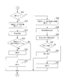
- step S01 shown in FIG. 9 the amount of change ⁇ V () is obtained by subtracting the previous voltage sensor output V (k ⁇ 1) from the voltage sensor output V (k) in the k-th calculation process using an arbitrary natural number k. k) is calculated.
- the amount of change ⁇ I is obtained by subtracting the current sensor output I (k ⁇ 1) after the previous error correction from the current sensor output I (k) after the error correction in the k-th calculation process using an arbitrary natural number k. (K) is calculated.
- step S02 every time the ON mode and the OFF state are switched when the execution of the second mode is instructed by the charging mode signal output from the charging mode determination unit 31 (for example, , Each change amount ⁇ V (k) of the voltage (voltage sensor output V) and current (current sensor output I) of the secondary battery 11 in the ON state to the OFF state or the transition from the OFF state to the ON state). , ⁇ I (k), the internal resistance R of the secondary battery 11 is calculated. In the calculation of the internal resistance R, for example, a sequential least square method using the above formula (2) is used.
- step S04 based on the open circuit voltage V 0 (k), the remaining capacity SOC (k) of the secondary battery 11 in the k-th calculation process is calculated, and the process proceeds to return.
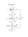
- step S11 a target value (target remaining charge) SOCT of the remaining capacity SOC of the secondary battery 11 when the external charger 1 charges the secondary battery 11 is acquired.
- step S12 the calculation result of the remaining capacity SOC output from the remaining capacity calculation unit 35 is acquired.
- step S13 it is determined whether the target remaining charge capacity SOCT is 100%. If this determination is “NO”, the flow proceeds to step S 18 described later. On the other hand, if the determination is “YES”, the flow proceeds to step S14. In step S14, it is determined whether or not the voltage sensor output V is larger than a predetermined upper limit voltage VH set for the secondary battery 11. If this determination is “NO”, the flow proceeds to step S 31 in FIG. On the other hand, if the determination is “YES”, the flow proceeds to step S15.
- step S15 the first mode is set as a charging mode by constant voltage (CV) charging that continuously outputs charging power of a constant voltage.
- step S16 the upper limit voltage VH is set as the required voltage Vreq for constant voltage (CV) charging.
- step S17 "1" is set to the flag value of the charge completion flag, and the process proceeds to return.
- Step S18 it is determined whether the remaining capacity SOC is larger than the target remaining charge SOCT. If this determination is “NO”, the flow proceeds to step S 31 in FIG. On the other hand, if the determination is “YES”, the flow proceeds to step S19.
- step S19 as the charging mode, the first mode by constant power (CP) charging that continuously outputs constant charging power such as rated power CPa is set.
- step S20 zero is set as the required power Preq for constant power (CP) charging, and the process proceeds to step S17 described above.
- step S31 shown in FIG. 11 it is determined whether or not the number of executions CNT of the second mode is greater than zero. If this determination is “YES”, the flow proceeds to step S 38 described later. On the other hand, if this determination is “NO”, the flow proceeds to step S 32.
- step S32 the first mode based on constant power (CP) charging that continues to output constant charging power such as rated power CPa is set as the charging mode.
- step S33 a predetermined rated power CPa is set as the required power Preq for constant power (CP) charging.
- step S34 for example, when the execution of the second mode is instructed every time the remaining capacity SOC reaches the predetermined remaining capacity MSOC after the start of charging, the second mode that is executed k-th time
- the remaining capacity SOC is not less than the predetermined remaining capacity MSOC (k) and not more than (predetermined remaining capacity MSOC (k) + hysteresis Shys) with respect to the predetermined remaining capacity MSOC (k) and the predetermined hysteresis Shsy. It is determined whether or not.
- the predetermined remaining capacity MSOC (k) is, for example, (10 ⁇ k)%. If this determination is “NO”, the flow proceeds to step S35.
- step S35 the number of executions CNT of the second mode is set to zero, and the process proceeds to step S36 in FIG.
- step S36 "0" is set to the flag value of the charge completion flag, and the process proceeds to return.
- step S37 the number of executions CNT of the second mode is set to “1”, and the process proceeds to step S36 in FIG.
- step S38 for example, a second mode based on an M-sequence signal is set as the charging mode.
- an M-sequence signal is generated.
- step S40 a value obtained by multiplying a predetermined rated power CPa by the M-sequence signal is set as the required power Preq for charging by the M-sequence signal.
- step S41 it is determined whether the second mode execution count CNT is less than a predetermined upper limit count TCNT. If this determination is “YES”, the flow proceeds to step S 42, and in this step S 42, the value obtained by adding “1” to the number of executions CNT in the second mode is newly set in the execution of the second mode. As the number of times CNT, the process proceeds to step S36 in FIG. On the other hand, if this determination is “NO”, the flow proceeds to step S 43, and in this step S 43, the second mode execution count CNT is set to zero, and the flow proceeds to step S 36 in FIG.
- step S51 it is determined whether any capacity estimation condition including at least the first capacity estimation condition among the first to sixth capacity estimation conditions is satisfied. If this determination is “NO”, the flow proceeds to step S 60 described later. On the other hand, if this determination is “YES”, the flow proceeds to step S52.
- step S52 the calculation result of the remaining capacity SOC output from the remaining capacity calculation unit 35 is acquired.
- step S53 as part of the third calculation execution condition described above, it is determined whether or not the elapsed time TT from the previous full charge capacity calculation is equal to or longer than a predetermined first time TT1. If this determination is “NO”, the flow proceeds to step S 60 described later. On the other hand, if this determination is “YES”, the flow proceeds to step S54.
- step S54 as part of the third calculation execution condition described above, it is determined whether or not the elapsed time TT from the previous full charge capacity calculation is equal to or shorter than a predetermined second time TT2. If this determination is “NO”, the flow proceeds to step S 59 described later. On the other hand, if this determination is “YES”, the flow proceeds to step S55.
- step S56 as the second calculation execution condition described above, whether the electric quantity ⁇ I, which is the integrated value of the current sensor output I after error correction from the previous full charge capacity calculation, is equal to or greater than a predetermined electric quantity. Determine whether. If this determination is “YES”, the flow proceeds to step S57.
- step S 60 as the fourth calculation execution condition described above, whether or not the calculated capacity value C0 described as shown in the above equation (5) falls within a predetermined capacity range (C2 ⁇ C0 ⁇ C1). Determine. If this determination is “YES”, the flow proceeds to the remaining capacity change calculation step (step S58). On the other hand, if this determination is “NO”, the flow proceeds to step S 60 described later.
- ) of the remaining capacity SOC since the latest full charge capacity calculation and the change amount ⁇ Ah ( Charged electric quantity (electric quantity ⁇ I), which is an integrated value of the current sensor output I after error correction of the current that has flown since the last full charge capacity calculation, and the current full charge capacity calculation count CNTC to “1”
- the new full charge capacity calculation count CNTC which is a value obtained by addition, is stored.
- step S59 the remaining capacity SOCP, which is the previous value, is set as the remaining capacity SOC of the current value, the electric quantity ⁇ I and the elapsed time TT are initialized to zero, and the process proceeds to step S61 described later.
- step S60 a value ( ⁇ I + I / (3600 ⁇ Ts)) obtained by adding the current value of the current sensor output I (s) after error correction to the previous value of the amount of electricity ⁇ I is calculated as the amount of electricity ⁇ I ( The current value of A ⁇ h). Then, a value obtained by relating a predetermined calculation cycle Ts to the previous value of the elapsed time TT is set as the current value of the elapsed time TT.
- step S61 it is determined whether or not the current full charge capacity calculation count CNTC is greater than the previous full charge capacity calculation count ESTN. If this determination is “NO”, the flow proceeds to the full charge capacity detection step (step S 63) described later. On the other hand, if this determination is “YES”, the flow proceeds to step S62.
- step S62 a value obtained by multiplying the full charge capacity CAPA (that is, the previous value of the full charge capacity CAPA) at the time of the previous full charge capacity calculation by an arbitrary weighting factor W (0 ⁇ W ⁇ 1) ( W ⁇ CAPA) and the value obtained by dividing the amount of change in electricity ⁇ Ah by the amount of change in remaining capacity SOC ⁇ SOC and multiplying by 100 ( ⁇ Ah / ⁇ SOC ⁇ 100) (1 ⁇ W) multiplied by a value ((1 ⁇ W) ⁇ ( ⁇ Ah / ⁇ SOC ⁇ 100)) and a value obtained by adding (W ⁇ CAPA + (1 ⁇ W) ⁇ ( ⁇ Ah / ⁇ SOC) X100)) is the current value of the full charge capacity CAPA.
- the previous full charge capacity calculation count ESTN is newly set as the current full charge capacity calculation count CNTC, and the process proceeds to step S63.
- step S63 a value obtained by multiplying the current value of the full charge capacity CAPA by an arbitrary filter coefficient F (0 ⁇ F ⁇ 1), and the full charge capacity after the filter processing at the time of the previous full charge capacity calculation.
- a value (F ⁇ CAPA + (1 ⁇ F) ⁇ CAPAF) obtained by adding the value obtained by multiplying CAPAF by the value (1 ⁇ F) by the filter coefficient F is the value of the secondary battery 11 after the filtering process.
- the current value of the full charge capacity CAPAF is detected, and the process proceeds to return.
- step S71 it is determined whether the second mode based on, for example, an M-sequence signal is set as the charging mode. If this determination is “NO”, the flow proceeds to step S 72, and in this step S 72, the duration TM is set to zero and the flow proceeds to return. On the other hand, if this determination is “YES”, the flow proceeds to step S73.
- step S73 it is determined whether it is an OFF state by which power transmission is stopped. If this determination is “NO”, the flow proceeds to step S 72 described above. On the other hand, when the determination result is “YES”, the OFF state duration TM is counted. In step S75, it is determined whether or not the duration time TM in the OFF state is equal to or longer than a predetermined delay time DT. If this determination is “NO”, the flow proceeds to return. On the other hand, if this determination is “YES”, the flow proceeds to step S76. In step S76, the current sensor output I is newly set as a reference value Ibase corresponding to the zero point (0A position) of the current sensor 19, and the process proceeds to return.
- step S81 shown in FIG. 14 it is determined whether or not a start switch for instructing start of the electric vehicle 10 is on. If this determination is “YES”, the flow proceeds to step S 82, in which the current sensor output I is set to the reference value Ibase (0) at the start, and the correction process for this second period is performed.
- the current correction value KRT (n) based on an arbitrary natural number n, which is the number of executions, is set to zero, and the process proceeds to return.
- this determination is “NO”
- the flow proceeds to step S83.
- step S83 it is determined whether or not the change amount (remaining capacity change amount) ⁇ SOC of the remaining capacity SOC in an appropriate period in the second period is greater than zero. If this determination is “NO”, the flow proceeds to step S 89 described later. On the other hand, if this determination is “YES”, the flow proceeds to step S84.
- the full charge capacity CAPAdrv is calculated based on the absolute value
- the full charge capacity CAPAchg is the full charge capacity CAPA of the calculation result output from the battery capacity calculation unit 38 in the first period. If this determination is “NO”, the flow proceeds to step S 87 described later. On the other hand, if this determination is “YES”, the flow proceeds to step S85.
- step S85 as the correction mode b described above, a value obtained by adding a predetermined correction gain Kg to the previous correction value KRT (n-1) is set as the current correction value KRT (n).
- step S86 the reference value Ibase (n) of the current sensor output I set in the n-th correction process using an arbitrary natural number n is changed to the reference value Ibase (0) at the start of the correction value KRT ( As a value obtained by adding n), the process proceeds to return.
- step S85 as the correction mode a described above, a value obtained by subtracting the predetermined correction gain Kg from the previous correction value KRT (n-1) is set as the current correction value KRT (n), and the above-described correction mode a is described above. The process proceeds to step S86.
- step S92 a value obtained by adding the predetermined correction gain Kg to the previous correction value KRT (n-1) as the correction mode d described above is set as the current correction value KRT (n), and the above-described correction mode d is described above.
- the process proceeds to step S86.
- the battery capacity detection method of the secondary battery As described above, according to the battery capacity detection method of the secondary battery according to the embodiment of the present invention, as the charging mode when the secondary battery 11 is charged by the charger 1, the ON state in which charging power is transmitted, In addition, an OFF state in which transmission of charging power is stopped (a power transmission stop state that can be actively executed at an appropriate timing) is provided, and the internal resistance R is sequentially calculated when switching between the ON state and the OFF state.
- accumulation of calculation errors due to changes in offset characteristics, hysteresis characteristics, and the like can be prevented, and deterioration in detection accuracy of the open-circuit voltage V 0 and the full charge capacity CAPA of the secondary battery 11 can be prevented.
- the open circuit voltage V 0 Detection error can be suppressed. For this reason, the internal resistance R of the secondary battery 11 can be calculated with high accuracy. Also, as in the conventional method, instead of the timing of charging and discharging currents of the secondary battery 11 becomes zero, since the detection timing of the open-circuit voltage V 0 when Ri switching of ON and OFF states, open circuit voltage V 0 The calculation accuracy of can be improved.
- the detection accuracy of the full charge capacity CAPA of the secondary battery 11 can be improved.
- the state for example, the drive state of the motor 12
- the internal resistance R is calculated every time the ON state and the OFF state are switched during one cycle of the second mode, and the pulse wave (ON state and ON state are different in duration).
- the internal resistance R is set based on different frequencies corresponding to, for example, changes in characteristics of the secondary battery 11 and the occurrence of various disturbance factors. It is possible to calculate with high accuracy.
- the error of the current sensor 19 is sequentially determined based on the detection result (current sensor output I) output from the current sensor 19. Since correction is performed, it is possible to prevent a decrease in the execution frequency of correction. For this reason, in the calculation result of the electric quantity ⁇ I based on the detection result output from the current sensor 19, accumulation of errors in the current sensor 19 can be suppressed, and the detection accuracy of the full charge capacity CAPA of the secondary battery 11 is improved. Can be made.
- the correction accuracy can be improved. For this reason, the detection accuracy of the full charge capacity CAPA of the secondary battery can be improved.
- an arbitrary weighting factor W is used for at least the previous past detection value (for example, full charge capacity CAPA (m ⁇ 1)) and the current detection value (for example, full charge capacity CAPA (m)).
- the detection value of the current full charge capacity CAPA (m) can be detected.
- the followability and stability of the detection result of the full charge capacity can be selected according to the purpose.
- priority can be given to the stability of detection results by increasing the weights of past detection values such as the previous time. it can.
- the filter process is performed with an arbitrary filter coefficient F, the change in the detection result of the full charge capacity CAPA can be smoothed.
- the internal resistance R can be calculated with high accuracy, and the calculation accuracy of the open circuit voltage V 0 based on the internal resistance R and the remaining capacity SOC based on the open circuit voltage V 0 can be improved. Furthermore, the calculation of the internal resistance R can be improved by reflecting the latest data immediately by using the successive least squares method and arbitrarily excluding past data.
- the voltage calculation value of the secondary battery 11 calculated based on the equivalent circuit model 50 for example, the open circuit voltage V 0
- the detection result of the voltage of the secondary battery 11 output from the voltage sensor 18 (voltage sensor output V ) Is equal to or less than a predetermined threshold value
- the calculation accuracy and reliability of the open-circuit voltage V 0 are equal to or higher than a certain level. For this reason, by calculating the full charge capacity when the difference between the voltage calculation value of the secondary battery 11 and the detection result of the voltage of the secondary battery 11 is equal to or less than a predetermined threshold, the remaining capacity based on the open voltage V 0 is calculated.
- the calculation accuracy and reliability of the full charge capacity CAPA based on the SOC and the remaining capacity SOC can be improved. That is, when the internal resistance R is calculated based on the equivalent circuit model 50, it can be determined that the actual behavior of the secondary battery 11 is accurately modeled by the equivalent circuit model 50. As a result, when any one of the plurality of first to sixth capacity estimation conditions is satisfied, including at least the first capacity estimation condition, the open state reflecting the accurate internal resistance R is opened. It is reflected in the voltage V 0. Therefore, the open voltage V 0 by it is possible to improve the accuracy of calculating the remaining capacity SOC, it is possible to reduce the calculation error of the full charge capacity CAPA.
- the internal resistance calculation unit 42 changes the internal resistance R of the secondary battery 11 by each change amount ⁇ V (k), ⁇ I (k) when switching between the ON state and the OFF state.
- the present invention is not limited to this, and the calculation may be performed by another calculation method when a desired calculation accuracy can be ensured.
- the full charge capacity CAPAdrv in the second period is calculated by a calculation process different from the full charge capacity CAPAchg in the first period. May be. Further, the full charge capacity CAPAdrv in the second period may be a full charge capacity calculated by another calculation process, not the full charge capacity CAPA output from the battery capacity calculation unit 38 in the second period. .
Landscapes
- Engineering & Computer Science (AREA)
- Power Engineering (AREA)
- Life Sciences & Earth Sciences (AREA)
- Sustainable Development (AREA)
- Sustainable Energy (AREA)
- Transportation (AREA)
- Mechanical Engineering (AREA)
- Secondary Cells (AREA)
- Tests Of Electric Status Of Batteries (AREA)
- Charge And Discharge Circuits For Batteries Or The Like (AREA)
Abstract
Description
本願は、2010年3月30日に、日本に出願された特願2010-076559号に基づき優先権を主張し、その内容をここに援用する。
この方法において、充放電電流の積算値は、第1および第2の検出タイミング間に電流センサにより検出される電池の充電電流および放電電流が積算されることにより算出される。また、残容量変化の演算においては、先ず、例えば電池の充放電電流がゼロとなるタイミングである各検出タイミングに、電圧センサにより電池の開放電圧が検出される。そして、予め設定された電池の開放電圧と残容量との対応関係から電池の開放電圧に対応する残容量が検出される。そして、これら第1および第2の検出タイミングにおける残容量から残容量変化が算出される。
しかしながら、例えば電池の経時変化や温度変化などにより特性変化が生じると、電池の充放電電流と開放電圧との対応関係が、予め設定された関数またはテーブルでの対応関係から変化する。このため、開放電圧の検出誤差が増大してしまうという問題が生じる。
また、電流センサから出力される電池の充電電流および放電電流の検出値から電池の充放電電流を演算する方法では、例えば電流センサの温度変化に伴うオフセット特性の変化やヒステリシス特性などによって演算誤差が蓄積すると、電池の開放電圧および満充電容量の検出精度が低下してしまう虞がある。
〔1〕本発明の第1態様に係る二次電池の電池容量検出方法は、外部充電器による充電が可能な電動車両に搭載された二次電池の電池容量検出方法であって、前記外部充電器による充電の際の充電モードが、充電電力を送電するON状態のみからなる第1モードと、前記ON状態および一時的に送電を停止するOFF状態からなる第2モードとを含み、前記外部充電器による充電の実行中に前記充電モードを選択する充電モード選択工程と;前記充電モード選択工程において前記第2モードが選択された場合に、前記ON状態と前記OFF状態との切替り時に前記二次電池の電圧および電流の変化量を用いて、前記二次電池の内部抵抗を算出する内部抵抗算出工程と;前記内部抵抗に基づいて前記二次電池の開放電圧を算出し、該算出の結果である前記開放電圧から前記二次電池の残容量を算出する残容量算出工程と;最近の満充電容量算出時からの前記残容量の変化量△SOC(=|SOC-SOCP|)を算出する残容量変化量算出工程と;最近の前記満充電容量算出時から流れた前記電流の積算値に応じて充電電気量を算出する充電電気量算出工程と;前記残容量変化量と前記充電電気量とに基づいて、前記二次電池の満充電容量を検出する満充電容量検出工程と;を有する。
また、外部充電器による充電中は、例えば高負荷電流などの外乱要因の発生が防がれるため、従来の検出タイミングに開放電圧等を検出する場合と比べて、内部抵抗、開放電圧および積算充電電流の算出精度を、より一層向上させることができる。以上により、二次電池の満充電容量の検出精度を向上させることができる。
また、開放電圧を検出するために、充電電力の送電を長時間停止する必要がなく、OFF状態の際に一時的に送電を停止することで開放電圧等を検出できる。このため、二次電池から負荷に電力が供給される放電時の負荷の状態(例えば、二次電池により駆動される電動車両駆動用モータの駆動状態など)の変化を防止できる。
本実施の形態による二次電池11の電池容量検出方法は、例えば図1に示すように、外部の充電器1による充電が可能な電動車両10に搭載された二次電池11の満充電容量を検出する方法である。
モータ12は、例えば3相(U相、V相、W相)のDCブラシレスモータが用いられる。モータ12の駆動力は、トランスミッション13およびディファレンシャル(図示略)を介して左右の駆動輪W,Wに配分されて伝達される。また、電動車両10の減速時に駆動輪W側からモータ12側に駆動力が伝達されると、モータ12は発電機として機能し、いわゆる回生制動力を発生して車体の運動エネルギーを電気エネルギーとして回収する。
モータ12はパワードライブユニット14に接続され、さらに、パワードライブユニット14は二次電池11に接続されている。
パワードライブユニット14は、モータECU15から出力される制御指令を受けてモータ12の駆動および回生を制御する。パワードライブユニット14は例えば、モータ12の駆動時に、二次電池11から出力される直流電力を3相交流電力に変換してモータ12へ供給する。また、パワードライブユニット14は、例えばモータ12の回生時に、モータ12から出力される3相交流電力を直流電力に変換して二次電池11に充電する。
また、電池ECU16は、後述するように、残容量SOCなどの状態量の算出結果に応じて、充電モード信号を出力する。この充電モード信号により、充電器1が二次電池11を充電するときの充電動作が指示される。
充電制御部22は、電池ECU16から出力された充電モード信号を受信すると、この充電モード信号に応じて充電電流供給回路21の動作(つまり、充電電力の出力)を制御する。
充電器1の各種の充電動作に対応する充電モードとして、充電電力を送電するON状態のみからなる第1モードと、ON状態および一時的に送電を停止するOFF状態からなる第2モードとが含まれている。充電モード信号が出力されることにより、これら充電モードのいずれかが選択される。
第2モードは、充電電力の送電が継続されるON状態に続いて充電電力の送電停止が継続されるOFF状態を少なくとも有する充電動作である。具体的には例えば、交互に繰り返されるON状態とOFF状態とを備えてもよいし、第1モードのON状態に続いて実行される場合には、OFF状態のみを備えているだけでもよい。
電流センサ誤差補正部33は、電流センサ19から出力された二次電池11の電流の検出値(電流センサ出力I)に基づき、電流センサ19の誤差(例えば、オフセット誤差およびヒステリシス誤差などからなる誤差)を検出するとともに、この誤差を補正する。そして、この誤差補正後の電流センサ出力Iを出力する。
この誤差の補正が実行可能な期間は、例えば、外部の充電器1による充電の実行中の第1期間と、この第1期間以外の期間である第2期間とのそれぞれとされている。また、この第2期間には、少なくとも電動車両10の走行時が含まれている。
そして、この補正が実行されるOFF状態の所定タイミングは、第2モードの実行中にON状態からOFF状態に移行した時点から二次電池11の実電流(電流の実値)がゼロとなるのに要する遅れ時間(後述する遅れ時間DT)が経過した後のタイミングとされている。
なお、任意の自然数nは、この第2期間の補正の処理が実行された回数である。

また、電流センサ出力Iの基準値Ibaseをマイナス側に補正する場合には、例えば、任意の自然数nによるn回目の補正の処理における補正値KRT(n)は、前回の補正の処理での補正値KRT(n-1)から、所定の補正ゲインKgが減算されて得られる値とされる。一方、電流センサ出力Iの基準値Ibaseをプラス側に補正する場合には、例えば、補正値KRT(n)は、前回の補正値KRT(n-1)に所定の補正ゲインKgが加算されて得られる値とされる。
第3の容量推定条件は、例えば、所定期間内での電流センサ出力Iの変化量△Iが所定電流変化量以下になることである。
第4の容量推定条件は、例えば、所定期間内での電圧センサ出力Vの変化量△Vが所定電圧変化量以下になることである。
第5の容量推定条件は、例えば、温度センサ20から出力された二次電池11の温度の検出値(温度センサ出力T)が所定温度以上になることである。
第6の容量推定条件は、例えば、後述する残容量算出部35により算出された二次電池11の開放電圧(開回路電圧)V0が所定電圧範囲内になることである。
残容量算出部35は、例えば図5に示すように、変化量演算部41と、内部抵抗演算部42と、開放電圧演算部43と、変換部44とを備えて構成されている。
例えば任意の自然数kによるk回目の算出処理での変化量△I(k)は、k回目の算出処理での誤差補正後の電流センサ出力I(k)から前回の誤差補正後の電流センサ出力I(k-1)が減算されて得られる値である。また、k回目の算出処理での変化量△V(k)は、k回目の算出処理での電圧センサ出力V(k)から前回の電圧センサ出力V(k-1)が減算されて得られる値である。
そして、変化量演算部41は、各変化量△I,△Vに所定の低域通過処理を行なって得られる各変化量△If,△Vfを出力する。

なお、外部の充電器1による充電中に電流センサ出力Iが積算されると、この積算値は充電電気量(電気量)ΣIとなる。
第1の演算実行条件は、例えば、後述する電池容量算出部38により満充電容量が前回に算出された時点(前回満充電容量算出時)からの残容量SOCの変化量(残容量変化量)△SOC(=|SOC-SOCP|)が、所定残容量変化量以上になることである。なお、この変化量△SOCは、この時点で残容量算出部35から出力された残容量SOCと、満充電容量が前回に算出された時点で残容量算出部35から出力された残容量SOCPとの差の絶対値とされている。
第3の演算実行条件は、例えば、後述する電池容量算出部38により満充電容量が前回に算出された時点からの経過時間TTが所定時間範囲内(TT2≧TT≧TT1)になることである。

先ず、以下に、二次電池11の残容量SOCを算出する残容量算出の処理方法について説明する。
例えば図9に示すステップS01においては、任意の自然数kによるk回目の算出処理での電圧センサ出力V(k)から前回の電圧センサ出力V(k-1)を減算して変化量△V(k)を算出する。また、任意の自然数kによるk回目の算出処理での誤差補正後における電流センサ出力I(k)から、前回の誤差補正後の電流センサ出力I(k-1)を減算して変化量△I(k)を算出する。
次に、残容量算出工程においては、まず、ステップS03において、前記内部抵抗Rに基づき、k回目(k=任意の自然数)の算出処理における開放電圧V0(k)を演算する。次に、ステップS04において、前記開放電圧V0(k)に基づき、k回目の算出処理における二次電池11の残容量SOC(k)を算出し、リターンに進む。
なお、この処理は、例えば所定の演算周期Ts(s)で繰り返し実行される。
例えば図10に示すステップS11においては、外部の充電器1が二次電池11を充電するときの二次電池11の残容量SOCの目標値(目標充電残容量)SOCTを取得する。
次に、ステップS12においては、残容量算出部35から出力される残容量SOCの算出結果を取得する。
この判定結果が「NO」の場合には、後述するステップS18に進む。
一方、この判定結果が「YES」の場合には、ステップS14に進む。
そして、ステップS14においては、電圧センサ出力Vが二次電池11に対して設定された所定の上限電圧VHよりも大きいか否かを判定する。
この判定結果が「NO」の場合には、後述する図11でのステップS31に進む。
一方、この判定結果が「YES」の場合には、ステップS15に進む。
次に、ステップS16においては、定電圧(CV)充電での要求電圧Vreqとして上限電圧VHを設定する。
次に、ステップS17においては、充電完了フラグのフラグ値に「1」を設定し、リターンに進む。
この判定結果が「NO」の場合には、後述する図11でのステップS31に進む。
一方、この判定結果が「YES」の場合には、ステップS19に進む。
次に、ステップS20においては、定電力(CP)充電での要求電力Preqとしてゼロを設定し、上述したステップS17に進む。
この判定結果が「YES」の場合には、後述するステップS38に進む。
一方、この判定結果が「NO」の場合には、ステップS32に進む。
そして、ステップS32においては、充電モードとして、定格電力CPaなどの一定の充電電力を出力し続ける定電力(CP)充電による第1モードを設定する。
次に、ステップS33においては、定電力(CP)充電での要求電力Preqとして所定の定格電力CPaを設定する。
この判定結果が「NO」の場合には、ステップS35に進む。このステップS35においては、第2モードの実行回数CNTをゼロとして、図10でのステップS36に進む。このステップS36においては、充電完了フラグのフラグ値に「0」を設定し、リターンに進む。
一方、この判定結果が「YES」の場合には、ステップS37に進む。このステップS37においては、第2モードの実行回数CNTを「1」として、図10でのステップS36に進む。
次に、ステップS39においては、M系列信号を生成する。
次に、ステップS40においては、このM系列信号による充電での要求電力Preqとして所定の定格電力CPaにM系列信号を乗算して得られる値を設定する。
この判定結果が「YES」の場合には、ステップS42に進み、このステップS42においては、第2モードの実行回数CNTに「1」を加算して得られる値を、新たに第2モードの実行回数CNTとして、図10でのステップS36に進む。
一方、この判定結果が「NO」の場合には、ステップS43に進み、このステップS43においては、第2モードの実行回数CNTをゼロとして、図10でのステップS36に進む。
なお、この処理は、例えば所定の演算周期Ts(s)で繰り返し実行される。
先ず、例えば図12に示すステップS51においては、第1~第6の容量推定条件のうち、少なくとも第1の容量推定条件を含む何れかの容量推定条件が成立したか否かを判定する。
この判定結果が「NO」の場合には、後述するステップS60に進む。
一方、この判定結果が「YES」の場合には、ステップS52に進む。
次に、ステップS53においては、上述した第3の演算実行条件の一部として、前回満充電容量算出時からの経過時間TTは所定の第1時間TT1以上か否かを判定する。
この判定結果が「NO」の場合には、後述するステップS60に進む。
一方、この判定結果が「YES」の場合には、ステップS54に進む。
そして、ステップS54においては、上述した第3の演算実行条件の一部として、前回満充電容量算出時からの経過時間TTは所定の第2時間TT2以下か否かを判定する。
この判定結果が「NO」の場合には、後述するステップS59に進む。
一方、この判定結果が「YES」の場合には、ステップS55に進む。
この判定結果が「YES」の場合には、ステップS56に進む。
一方、この判定結果が「NO」の場合には、後述するステップS60に進む。
そして、ステップS56においては、上述した第2の演算実行条件として、前回満充電容量算出時からの誤差補正後の電流センサ出力Iの積算値である電気量ΣIは所定電気量以上であるか否かを判定する。
この判定結果が「YES」の場合には、ステップS57に進む。
一方、この判定結果が「NO」の場合には、後述するステップS60に進む。
そして、ステップS57においては、上述した第4の演算実行条件として、上記数式(5)に示すように記述される容量算出値C0が所定容量範囲内(C2≧C0≧C1)になるか否かを判定する。
この判定結果が「YES」の場合には、残容量変化量算出工程(ステップS58)に進む。
一方、この判定結果が「NO」の場合には、後述するステップS60に進む。
また、ステップS60においては、電気量ΣIの前回値に誤差補正後の電流センサ出力I(s)の今回値を加算して得られる値(ΣI+I/(3600×Ts))を、電気量ΣI(A・h)の今回値とする。そして、経過時間TTの前回値に所定の演算周期Tsを関して得られる値を経過時間TTの今回値とする。
この判定結果が「NO」の場合には、後述する満充電容量検出工程(ステップS63)に進む。
一方、この判定結果が「YES」の場合には、ステップS62に進む。
先ず、例えば図13に示すステップS71においては、充電モードとして、例えばM系列信号による第2モードが設定されているか否かを判定する。
この判定結果が「NO」の場合には、ステップS72に進み、このステップS72においては、継続時間TMをゼロとして、リターンに進む。
一方、この判定結果が「YES」の場合には、ステップS73に進む。
この判定結果が「NO」の場合には、上述したステップS72に進む。
一方、この判定結果が「YES」の場合には、OFF状態の継続時間TMを計時する。
そして、ステップS75においては、OFF状態の継続時間TMが所定の遅れ時間DT以上であるか否かを判定する。
この判定結果が「NO」の場合には、リターンに進む。
一方、この判定結果が「YES」の場合には、ステップS76に進む。
そして、ステップS76においては、電流センサ出力Iを、新たに電流センサ19のゼロ点(0Aの位置)に対応する基準値Ibaseとして設定し、リターンに進む。
先ず、例えば図14に示すステップS81においては、電動車両10の始動を指示する始動スイッチがオンであるか否かを判定する。
この判定結果が「YES」の場合には、ステップS82に進み、このステップS82においては、電流センサ出力Iを始動時の基準値Ibase(0)に設定し、この第2期間の補正の処理が実行された回数である任意の自然数nによる今回の補正値KRT(n)をゼロとして、リターンに進む。
一方、この判定結果が「NO」の場合には、ステップS83に進む。
この判定結果が「NO」の場合には、後述するステップS89に進む。
一方、この判定結果が「YES」の場合には、ステップS84に進む。
この判定結果が「NO」の場合には、後述するステップS87に進む。
一方、この判定結果が「YES」の場合には、ステップS85に進む。
次に、ステップS86においては、任意の自然数nによるn回目の補正の処理で設定される電流センサ出力Iの基準値Ibase(n)を、始動時の基準値Ibase(0)に補正値KRT(n)を加算して得られる値として、リターンに進む。
この判定結果が「NO」の場合には、上述したステップS86に進む。
一方、この判定結果が「YES」の場合には、ステップS88に進む。
そして、ステップS85においては、上述した補正モードaとして、前回の補正値KRT(n-1)から所定の補正ゲインKgを減算して得た値を、今回の補正値KRT(n)とし、上述したステップS86に進む。
この判定結果が「NO」の場合には、上述したステップS91に進む。
一方、この判定結果が「YES」の場合には、ステップS90に進む。
そして、ステップS90においては、上述した補正モードcとして、前回の補正値KRT(n-1)から所定の補正ゲインKgを減算して得た値を、今回の補正値KRT(n)とし、上述したステップS86に進む。
この判定結果が「NO」の場合には、上述したステップS86に進む。
一方、この判定結果が「YES」の場合には、ステップS92に進む。
そして、ステップS92においては、上述した補正モードdとして、前回の補正値KRT(n-1)に所定の補正ゲインKgを加算して得た値を、今回の補正値KRT(n)とし、上述したステップS86に進む。
また、開放電圧V0を検出するために充電電力の送電を長時間停止することなく、OFF状態の際に一時的に送電を停止することで開放電圧V0等を検出できる。このため、二次電池11からモータ12などの負荷に電力が供給されることにより放電時の負荷の状態(例えば、モータ12の駆動状態など)が変化してしまうことを防止できる。
さらに、任意のフィルタ係数Fによるフィルタ処理を行なうことから、満充電容量CAPAの検出結果の変化を滑らかにすることができる。
さらに、逐次最小二乗法により、最新のデータを即時に反映して、過去のデータを任意に排除して、内部抵抗Rの算出精度を向上させることができる。
つまり、等価回路モデル50に基づき内部抵抗Rを算出した場合には、二次電池11の実際の挙動を等価回路モデル50により精度良くモデル化していると判断できる。これにより、複数の第1~第6の容量推定条件のうち、少なくとも第1の容量推定条件を含む何れかの容量推定条件が成立した場合には、精度の良い内部抵抗Rが反映された開放電圧V0に反映される。よって、開放電圧V0による残容量SOCの算出精度を向上させることができ、満充電容量CAPAの算出誤差を低減することができる。
10 電動車両
11 二次電池
16 電池ECU
18 電圧センサ
19 電流センサ
20 温度センサ
31 充電モード決定部
32 通信部
33 電流センサ誤差補正部
34 容量推定条件成立判定部
35 残容量算出部
36 電流積算算出部
37 演算実行条件成立判定部
38 電池容量算出部ステップ
S02 内部抵抗算出工程ステップ
S04 残容量算出工程ステップ
S11~S22およびS31~S37 充電モード選択工程ステップ
S58 残容量変化量算出工程、充電電気量算出工程ステップ
S63 満充電容量検出工程ステップ
S71~S76 電流センサ誤差補正工程
Claims (7)
- 外部充電器による充電が可能な電動車両に搭載された二次電池の電池容量検出方法であって、
前記外部充電器による充電の際の充電モードが、充電電力を送電するON状態のみからなる第1モードと、前記ON状態および一時的に送電を停止するOFF状態からなる第2モードとを含み、
前記外部充電器による充電の実行中に前記充電モードを選択する充電モード選択工程と;
前記充電モード選択工程において前記第2モードが選択された場合に、前記ON状態と前記OFF状態との切替り時に前記二次電池の電圧および電流の変化量を用いて、前記二次電池の内部抵抗を算出する内部抵抗算出工程と;
前記内部抵抗に基づいて前記二次電池の開放電圧を算出し、該算出の結果である前記開放電圧から前記二次電池の残容量を算出する残容量算出工程と;
最近の満充電容量算出時からの前記残容量の変化量を算出する残容量変化量算出工程と;
最近の前記満充電容量算出時から流れた前記電流の積算値に応じて充電電気量を算出する充電電気量算出工程と;
前記残容量変化量と前記充電電気量とに基づいて、前記二次電池の満充電容量を検出する満充電容量検出工程と;
を有することを特徴とする二次電池の電池容量検出方法。 - 前記充電モード選択工程において前記第2モードが選択された場合に、
前記外部充電器による充電を、前記ON状態及び前記OFF状態の継続時間が異なるパルス波を持つ前記充電電力の送電により行い;かつ、
前記内部抵抗算出工程で、前記ON状態と前記OFF状態とが切替る毎に前記内部抵抗を算出し;かつ、
前記残容量算出工程で、前記第2モードの一周期内に前記内部抵抗算出工程において算出された前記内部抵抗を用いて前記開放電圧を算出する;
ことを特徴とする請求項1に記載の二次電池の電池容量検出方法。 - 前記充電モード選択工程において前記第2モードが選択された場合に、
前記二次電池の前記電流を検出する電流センサから出力された前記OFF状態のときの前記電流の検出結果から前記電流センサの誤差を検出して、この誤差を用いて補正を行なう電流センサ誤差補正工程をさらに有する
ことを特徴とする請求項1または請求項2に記載の二次電池の電池容量検出方法。 - 前記電流センサ誤差補正工程で、前記ON状態から前記OFF状態に移行する毎に前記誤差を検出し、かつ、前記第2モードの一周期内に検出した前記誤差を平均して得た値を用いて前記補正を行なうことを特徴とする請求項3に記載の二次電池の電池容量検出方法。
- 前記満充電容量検出工程で、前記残容量変化量および前記充電電気量に基づいて検出した前記満充電容量の今回の検出値と、前記満充電容量の少なくとも最近の検出値とを任意の重み係数を掛けて得られた値を、新たに前記満充電容量の今回の検出値とすることを特徴とする請求項1または請求項2に記載の二次電池の電池容量検出方法。
- 前記内部抵抗算出工程で、
前記ON状態と前記OFF状態の切替り時における前記電流の変化量と;
前記二次電池の電圧を検出する電圧センサから出力された前記ON状態と前記OFF状態の切替り時の前記電圧の変化量と;
を用いて、前記内部抵抗値を算出する
ことを特徴とする請求項1または請求項2に記載の二次電池の電池容量検出方法。 - 前記残容量算出工程で、
等価回路モデルに基づいて演算された前記二次電池の電圧演算値と前記二次電池の電圧を検出する電圧センサから出力された前記電圧の検出結果との差が所定の閾値以下の場合に、前記残容量を算出する
ことを特徴とする請求項1または請求項2に記載の二次電池の電池容量検出方法。
Priority Applications (4)
| Application Number | Priority Date | Filing Date | Title |
|---|---|---|---|
| US13/637,946 US9566875B2 (en) | 2010-03-30 | 2011-03-11 | Method of detecting battery capacity of secondary battery |
| JP2012508198A JP5629760B2 (ja) | 2010-03-30 | 2011-03-11 | 二次電池の電池容量検出方法 |
| EP11762550.9A EP2555008A4 (en) | 2010-03-30 | 2011-03-11 | METHOD FOR DETECTING THE BATTERY CAPACITY OF A SECONDARY BATTERY |
| CN201180015118.6A CN102869999B (zh) | 2010-03-30 | 2011-03-11 | 二次电池的电池容量检测方法 |
Applications Claiming Priority (2)
| Application Number | Priority Date | Filing Date | Title |
|---|---|---|---|
| JP2010-076559 | 2010-03-30 | ||
| JP2010076559 | 2010-03-30 |
Publications (1)
| Publication Number | Publication Date |
|---|---|
| WO2011122310A1 true WO2011122310A1 (ja) | 2011-10-06 |
Family
ID=44712032
Family Applications (1)
| Application Number | Title | Priority Date | Filing Date |
|---|---|---|---|
| PCT/JP2011/055821 WO2011122310A1 (ja) | 2010-03-30 | 2011-03-11 | 二次電池の電池容量検出方法 |
Country Status (5)
| Country | Link |
|---|---|
| US (1) | US9566875B2 (ja) |
| EP (1) | EP2555008A4 (ja) |
| JP (1) | JP5629760B2 (ja) |
| CN (1) | CN102869999B (ja) |
| WO (1) | WO2011122310A1 (ja) |
Cited By (8)
| Publication number | Priority date | Publication date | Assignee | Title |
|---|---|---|---|---|
| CN103472744A (zh) * | 2013-09-23 | 2013-12-25 | 天地融科技股份有限公司 | 动态令牌工作状态的控制方法、装置及动态令牌 |
| JP2014522488A (ja) * | 2012-03-16 | 2014-09-04 | エルジー・ケム・リミテッド | バッテリー状態推定装置及び方法 |
| CN104698385A (zh) * | 2013-12-06 | 2015-06-10 | 株式会社东芝 | 电池状态计算装置和电池状态计算方法 |
| US10670660B2 (en) * | 2012-02-29 | 2020-06-02 | Envision Aesc Energy Devices Ltd. | Battery pack and method for calculating electric energy of battery pack |
| JP2021012036A (ja) * | 2019-07-03 | 2021-02-04 | 株式会社デンソーテン | 推定装置、電池システムおよび推定方法 |
| JP2022069459A (ja) * | 2020-06-22 | 2022-05-11 | レノボ・シンガポール・プライベート・リミテッド | 充電制御装置、二次電池、電子機器、及び制御方法 |
| US11817732B2 (en) | 2020-06-22 | 2023-11-14 | Lenovo (Singapore) Pte. Ltd. | Charing controller, rechargeable battery, electronic device, and control method |
| WO2024014244A1 (ja) * | 2022-07-12 | 2024-01-18 | 株式会社Gsユアサ | 情報処理装置、蓄電デバイス、情報処理方法及びプログラム |
Families Citing this family (33)
| Publication number | Priority date | Publication date | Assignee | Title |
|---|---|---|---|---|
| KR101835007B1 (ko) * | 2011-10-25 | 2018-03-07 | 삼성전자주식회사 | 휴대용 단말기에서 충전 전류를 제어하기 위한 장치 및 방법 |
| JP6135110B2 (ja) * | 2012-03-08 | 2017-05-31 | 日産自動車株式会社 | 二次電池の制御装置、充電制御方法およびsoc検出方法 |
| JP6065561B2 (ja) | 2012-03-08 | 2017-01-25 | 日産自動車株式会社 | 二次電池の制御装置およびsoc検出方法 |
| JP5621818B2 (ja) * | 2012-08-08 | 2014-11-12 | トヨタ自動車株式会社 | 蓄電システムおよび均等化方法 |
| US9705349B2 (en) * | 2012-09-21 | 2017-07-11 | Nissan Motor Co., Ltd. | Charge control device and charge time calculation method |
| JP5812032B2 (ja) * | 2013-03-22 | 2015-11-11 | トヨタ自動車株式会社 | 蓄電システム及び蓄電装置の満充電容量推定方法 |
| JP6263771B2 (ja) * | 2013-12-26 | 2018-01-24 | 三菱自動車工業株式会社 | 車両の駆動用電池劣化判定装置 |
| US9272634B2 (en) * | 2014-02-20 | 2016-03-01 | Ford Global Technologies, Llc | Active battery system estimation request generation |
| US9718455B2 (en) | 2014-02-20 | 2017-08-01 | Ford Global Technologies, Llc | Active battery parameter identification using conditional extended kalman filter |
| US9381825B2 (en) | 2014-02-20 | 2016-07-05 | Ford Global Technologies, Llc | State of charge quality based cell balancing control |
| US9539912B2 (en) | 2014-02-20 | 2017-01-10 | Ford Global Technologies, Llc | Battery capacity estimation using state of charge initialization-on-the-fly concept |
| CN103944230B (zh) * | 2014-04-25 | 2016-06-29 | 可牛网络技术(北京)有限公司 | 移动终端的充电系统、方法及充电器 |
| CN104354604A (zh) * | 2014-11-25 | 2015-02-18 | 淄博洁力特种电池材料科技有限公司 | 一种电动汽车电池充电方法及充电装置 |
| CN104502850B (zh) * | 2014-12-12 | 2017-10-24 | 惠州Tcl移动通信有限公司 | 一种基于移动终端的电池能量密度检测方法及系统 |
| US10282476B2 (en) * | 2014-12-18 | 2019-05-07 | International Business Machines Corporation | Acquisition and transfer of tacit knowledge |
| DE112015006416B4 (de) * | 2015-04-03 | 2019-03-21 | Mitsubishi Electric Corporation | Batterieladungszustandsschätzvorrichtung und Ladungszustandsschätzverfahren |
| US10353007B2 (en) * | 2015-05-28 | 2019-07-16 | Mitsubishi Electric Corporation | Rechargeable battery parameter estimation apparatus and rechargeable battery parameter estimation method for calculating first and second coefficients which are partial derivatives of an estimated value of the battery state-of-charge |
| AU2016203834A1 (en) * | 2015-06-17 | 2017-01-12 | Gs Yuasa International Ltd. | State estimation device and state estimation method |
| JP6569540B2 (ja) * | 2016-01-13 | 2019-09-04 | 株式会社Gsユアサ | 車載電源システムおよびこれに含まれるバッテリの状態検知方法 |
| JP6220904B2 (ja) * | 2016-01-14 | 2017-10-25 | 本田技研工業株式会社 | 蓄電装置 |
| EP3410137B1 (en) * | 2016-01-29 | 2020-03-11 | Hitachi Automotive Systems, Ltd. | Cell state estimation device, cell control device, cell system, and cell state estimation method |
| US11411421B2 (en) * | 2016-02-02 | 2022-08-09 | Toyota Motor Europe | Control device and method for charging a rechargeable battery |
| US9925888B2 (en) | 2016-03-02 | 2018-03-27 | Ford Global Technologies, Llc | Battery cell state of charge initialization in a presence of voltage measurement uncertainty |
| JP6481661B2 (ja) * | 2016-06-10 | 2019-03-13 | トヨタ自動車株式会社 | 電池システム |
| WO2019043828A1 (ja) * | 2017-08-30 | 2019-03-07 | 三菱電機株式会社 | コンデンサ容量測定装置及び電力用機器 |
| JP6641334B2 (ja) * | 2017-09-29 | 2020-02-05 | 本田技研工業株式会社 | 電池容量推定装置、方法及びプログラム |
| CN111480087A (zh) * | 2017-12-13 | 2020-07-31 | 住友电气工业株式会社 | 电池监视装置、计算机程序和电池监视方法 |
| JP6729616B2 (ja) * | 2018-03-08 | 2020-07-22 | カシオ計算機株式会社 | 電子機器、給電制御方法、及びプログラム |
| CN110888069A (zh) * | 2018-08-15 | 2020-03-17 | 上海汽车集团股份有限公司 | 一种动力电池的电流检测方法及装置 |
| JP2020187021A (ja) * | 2019-05-15 | 2020-11-19 | 本田技研工業株式会社 | 二次電池の残容量表示方法、表示装置、及び電動車両 |
| US20210021134A1 (en) * | 2019-07-18 | 2021-01-21 | Save The Planet Co., Ltd. | Storage system |
| KR102704741B1 (ko) | 2022-05-03 | 2024-09-09 | 주식회사 원익피앤이 | 배터리 검사를 위한 통합 시스템 및 컨트롤러의 작동 방법 |
| CN117713273B (zh) * | 2023-10-31 | 2024-06-11 | 东莞市安泰电子科技有限公司 | 一种智能化电能管理系统 |
Citations (5)
| Publication number | Priority date | Publication date | Assignee | Title |
|---|---|---|---|---|
| JPH07274411A (ja) * | 1994-03-30 | 1995-10-20 | Mitsubishi Electric Corp | 車両用発電制御装置 |
| JP2008241358A (ja) | 2007-03-26 | 2008-10-09 | Sanyo Electric Co Ltd | 電池の満充電容量検出方法 |
| JP2009017779A (ja) * | 2006-06-13 | 2009-01-22 | Kyocera Corp | 携帯通信端末 |
| JP2010019664A (ja) * | 2008-07-10 | 2010-01-28 | Nippon Soken Inc | 電池劣化検出装置および方法 |
| JP2010076559A (ja) | 2008-09-25 | 2010-04-08 | Toyoda Gosei Co Ltd | ステアリングホイール |
Family Cites Families (12)
| Publication number | Priority date | Publication date | Assignee | Title |
|---|---|---|---|---|
| JP3402669B2 (ja) * | 1993-07-09 | 2003-05-06 | 三洋電機株式会社 | 吸収冷凍機の制御方法 |
| JP3069498B2 (ja) | 1994-09-01 | 2000-07-24 | 富士通株式会社 | 充放電装置および電子機器 |
| US5789924A (en) * | 1997-03-20 | 1998-08-04 | Sanyo Electric Co., Ltd. | Method of calculating rechargeable battery charge capacity |
| JP3879278B2 (ja) | 1998-11-10 | 2007-02-07 | 日産自動車株式会社 | ハイブリッド車の充電量演算方法および充電量演算装置 |
| JP3669234B2 (ja) | 1999-11-15 | 2005-07-06 | 新神戸電機株式会社 | 組電池の充電制御装置 |
| JP2002142379A (ja) | 2000-11-06 | 2002-05-17 | Sanyo Electric Co Ltd | 電池の充電方法 |
| JP3926699B2 (ja) | 2002-07-30 | 2007-06-06 | 株式会社リコー | 二次電池の充電装置及びその充電方法 |
| JP4638251B2 (ja) * | 2005-02-07 | 2011-02-23 | 富士重工業株式会社 | バッテリの管理装置 |
| JP4816097B2 (ja) | 2006-01-20 | 2011-11-16 | 日産自動車株式会社 | 電池のsoc算出装置 |
| JP5393956B2 (ja) | 2007-04-10 | 2014-01-22 | 三洋電機株式会社 | 電池の満充電容量検出方法 |
| JP4544273B2 (ja) * | 2007-06-20 | 2010-09-15 | トヨタ自動車株式会社 | 車両用電源装置および車両用電源装置における蓄電装置の充電状態推定方法 |
| JP2010019758A (ja) | 2008-07-11 | 2010-01-28 | Mitsumi Electric Co Ltd | 電池状態検知装置 |
-
2011
- 2011-03-11 EP EP11762550.9A patent/EP2555008A4/en not_active Withdrawn
- 2011-03-11 WO PCT/JP2011/055821 patent/WO2011122310A1/ja active Application Filing
- 2011-03-11 JP JP2012508198A patent/JP5629760B2/ja not_active Expired - Fee Related
- 2011-03-11 US US13/637,946 patent/US9566875B2/en active Active
- 2011-03-11 CN CN201180015118.6A patent/CN102869999B/zh active Active
Patent Citations (5)
| Publication number | Priority date | Publication date | Assignee | Title |
|---|---|---|---|---|
| JPH07274411A (ja) * | 1994-03-30 | 1995-10-20 | Mitsubishi Electric Corp | 車両用発電制御装置 |
| JP2009017779A (ja) * | 2006-06-13 | 2009-01-22 | Kyocera Corp | 携帯通信端末 |
| JP2008241358A (ja) | 2007-03-26 | 2008-10-09 | Sanyo Electric Co Ltd | 電池の満充電容量検出方法 |
| JP2010019664A (ja) * | 2008-07-10 | 2010-01-28 | Nippon Soken Inc | 電池劣化検出装置および方法 |
| JP2010076559A (ja) | 2008-09-25 | 2010-04-08 | Toyoda Gosei Co Ltd | ステアリングホイール |
Non-Patent Citations (1)
| Title |
|---|
| See also references of EP2555008A4 |
Cited By (11)
| Publication number | Priority date | Publication date | Assignee | Title |
|---|---|---|---|---|
| US10670660B2 (en) * | 2012-02-29 | 2020-06-02 | Envision Aesc Energy Devices Ltd. | Battery pack and method for calculating electric energy of battery pack |
| JP2014522488A (ja) * | 2012-03-16 | 2014-09-04 | エルジー・ケム・リミテッド | バッテリー状態推定装置及び方法 |
| CN103472744A (zh) * | 2013-09-23 | 2013-12-25 | 天地融科技股份有限公司 | 动态令牌工作状态的控制方法、装置及动态令牌 |
| CN103472744B (zh) * | 2013-09-23 | 2016-01-06 | 天地融科技股份有限公司 | 动态令牌工作状态的控制方法、装置及动态令牌 |
| CN104698385A (zh) * | 2013-12-06 | 2015-06-10 | 株式会社东芝 | 电池状态计算装置和电池状态计算方法 |
| JP2021012036A (ja) * | 2019-07-03 | 2021-02-04 | 株式会社デンソーテン | 推定装置、電池システムおよび推定方法 |
| JP7271343B2 (ja) | 2019-07-03 | 2023-05-11 | 株式会社デンソーテン | 推定装置、電池システムおよび推定方法 |
| JP2022069459A (ja) * | 2020-06-22 | 2022-05-11 | レノボ・シンガポール・プライベート・リミテッド | 充電制御装置、二次電池、電子機器、及び制御方法 |
| JP7238180B2 (ja) | 2020-06-22 | 2023-03-13 | レノボ・シンガポール・プライベート・リミテッド | 充電制御装置、二次電池、電子機器、及び制御方法 |
| US11817732B2 (en) | 2020-06-22 | 2023-11-14 | Lenovo (Singapore) Pte. Ltd. | Charing controller, rechargeable battery, electronic device, and control method |
| WO2024014244A1 (ja) * | 2022-07-12 | 2024-01-18 | 株式会社Gsユアサ | 情報処理装置、蓄電デバイス、情報処理方法及びプログラム |
Also Published As
| Publication number | Publication date |
|---|---|
| US9566875B2 (en) | 2017-02-14 |
| JP5629760B2 (ja) | 2014-11-26 |
| CN102869999B (zh) | 2015-07-22 |
| JPWO2011122310A1 (ja) | 2013-07-08 |
| US20130013238A1 (en) | 2013-01-10 |
| CN102869999A (zh) | 2013-01-09 |
| EP2555008A1 (en) | 2013-02-06 |
| EP2555008A4 (en) | 2013-08-28 |
Similar Documents
| Publication | Publication Date | Title |
|---|---|---|
| JP5629760B2 (ja) | 二次電池の電池容量検出方法 | |
| JP5393624B2 (ja) | 電池容量算出装置および電池容量算出方法 | |
| KR101414890B1 (ko) | 2차 배터리용 용량 추정 장치 | |
| US9316697B2 (en) | Management system and estimating method for battery parameter | |
| JP5419832B2 (ja) | 電池容量算出装置および電池容量算出方法 | |
| US6107779A (en) | Apparatus for detecting remaining capacity of battery | |
| JP5573818B2 (ja) | 電池均等化装置および方法 | |
| JP6426267B2 (ja) | 電池制御装置、および、車両システム | |
| JP4762505B2 (ja) | バッテリのウォームアップ制御装置 | |
| US10547239B2 (en) | Voltage converter control apparatus configured to determine a normal duty ratio range based on a command value for the output voltage | |
| JP5784108B2 (ja) | 充電制御装置 | |
| US20130080096A1 (en) | Arithmetic processing apparatus for calculating internal resistance/open-circuit voltage of secondary battery | |
| US20120306450A1 (en) | Semiconductor Integrated Circuit Having Battery Control Function and Operation Method Thereof | |
| US20130311119A1 (en) | Method of detecting battery full-charge capacity | |
| JP5397013B2 (ja) | 組電池の制御装置 | |
| JP6534746B2 (ja) | 電池制御装置及び電池システム | |
| JP2003057321A (ja) | 二次電池の出力劣化演算装置および方法 | |
| JP2000150003A (ja) | ハイブリッド車の充電量演算方法および充電量演算装置 | |
| JP2011209086A (ja) | 電流センサの誤差補正方法 | |
| WO2010140235A1 (ja) | 群電池充電率演算装置、群電池充電率演算方法、プログラム、及び群電池soc表示装置 | |
| JP6776904B2 (ja) | 電池パック及び電源システム | |
| JP2006174597A (ja) | ハイブリッド車のバッテリウォームアップ制御装置 | |
| JP2000306613A (ja) | バッテリ状態監視装置 | |
| US11811257B2 (en) | Method for controlling a power supply device of an electrical system | |
| JP2006174596A (ja) | ハイブリッド車のバッテリウォームアップ制御装置 |
Legal Events
| Date | Code | Title | Description |
|---|---|---|---|
| WWE | Wipo information: entry into national phase |
Ref document number: 201180015118.6 Country of ref document: CN |
|
| 121 | Ep: the epo has been informed by wipo that ep was designated in this application |
Ref document number: 11762550 Country of ref document: EP Kind code of ref document: A1 |
|
| WWE | Wipo information: entry into national phase |
Ref document number: 2012508198 Country of ref document: JP |
|
| WWE | Wipo information: entry into national phase |
Ref document number: 13637946 Country of ref document: US |
|
| WWE | Wipo information: entry into national phase |
Ref document number: 2011762550 Country of ref document: EP |
|
| NENP | Non-entry into the national phase |
Ref country code: DE |