WO2011122303A1 - ガラスブランクの製造方法、磁気記録媒体基板の製造方法および磁気記録媒体の製造方法 - Google Patents
ガラスブランクの製造方法、磁気記録媒体基板の製造方法および磁気記録媒体の製造方法 Download PDFInfo
- Publication number
- WO2011122303A1 WO2011122303A1 PCT/JP2011/055753 JP2011055753W WO2011122303A1 WO 2011122303 A1 WO2011122303 A1 WO 2011122303A1 JP 2011055753 W JP2011055753 W JP 2011055753W WO 2011122303 A1 WO2011122303 A1 WO 2011122303A1
- Authority
- WO
- WIPO (PCT)
- Prior art keywords
- molten glass
- glass
- press
- lump
- molding
- Prior art date
- Legal status (The legal status is an assumption and is not a legal conclusion. Google has not performed a legal analysis and makes no representation as to the accuracy of the status listed.)
- Ceased
Links
Images










Classifications
-
- G—PHYSICS
- G11—INFORMATION STORAGE
- G11B—INFORMATION STORAGE BASED ON RELATIVE MOVEMENT BETWEEN RECORD CARRIER AND TRANSDUCER
- G11B5/00—Recording by magnetisation or demagnetisation of a record carrier; Reproducing by magnetic means; Record carriers therefor
- G11B5/84—Processes or apparatus specially adapted for manufacturing record carriers
- G11B5/8404—Processes or apparatus specially adapted for manufacturing record carriers manufacturing base layers
-
- C—CHEMISTRY; METALLURGY
- C03—GLASS; MINERAL OR SLAG WOOL
- C03B—MANUFACTURE, SHAPING, OR SUPPLEMENTARY PROCESSES
- C03B11/00—Pressing molten glass or performed glass reheated to equivalent low viscosity without blowing
- C03B11/06—Construction of plunger or mould
- C03B11/08—Construction of plunger or mould for making solid articles, e.g. lenses
- C03B11/088—Flat discs
-
- C—CHEMISTRY; METALLURGY
- C03—GLASS; MINERAL OR SLAG WOOL
- C03B—MANUFACTURE, SHAPING, OR SUPPLEMENTARY PROCESSES
- C03B7/00—Distributors for the molten glass; Means for taking-off charges of molten glass; Producing the gob, e.g. controlling the gob shape, weight or delivery tact
- C03B7/10—Cutting-off or severing the glass flow with the aid of knives or scissors or non-contacting cutting means, e.g. a gas jet; Construction of the blades used
-
- C—CHEMISTRY; METALLURGY
- C03—GLASS; MINERAL OR SLAG WOOL
- C03B—MANUFACTURE, SHAPING, OR SUPPLEMENTARY PROCESSES
- C03B2215/00—Press-moulding glass
- C03B2215/70—Horizontal or inclined press axis
-
- Y—GENERAL TAGGING OF NEW TECHNOLOGICAL DEVELOPMENTS; GENERAL TAGGING OF CROSS-SECTIONAL TECHNOLOGIES SPANNING OVER SEVERAL SECTIONS OF THE IPC; TECHNICAL SUBJECTS COVERED BY FORMER USPC CROSS-REFERENCE ART COLLECTIONS [XRACs] AND DIGESTS
- Y02—TECHNOLOGIES OR APPLICATIONS FOR MITIGATION OR ADAPTATION AGAINST CLIMATE CHANGE
- Y02P—CLIMATE CHANGE MITIGATION TECHNOLOGIES IN THE PRODUCTION OR PROCESSING OF GOODS
- Y02P40/00—Technologies relating to the processing of minerals
- Y02P40/50—Glass production, e.g. reusing waste heat during processing or shaping
- Y02P40/57—Improving the yield, e-g- reduction of reject rates
Definitions
- the present invention relates to a glass blank manufacturing method, a magnetic recording medium substrate manufacturing method, and a magnetic recording medium manufacturing method.
- a method of manufacturing a magnetic recording medium substrate typically, (1) a method of producing a molten glass lump through a press forming step of pressing a molten glass lump with a pair of press forming dies (hereinafter referred to as “press”). And a method (hereinafter referred to as “sheet-like”), and (2) a method of cutting a sheet-like glass into a disk shape by a float method, a downdraw method, or the like. It may be referred to as “glass cutting method” (see Patent Document 2 etc.).
- a lapping process (rough polishing process) and a polishing process (precision polishing) are performed as a polishing process after a disk processing process for processing the sheet glass into a disk shape.
- the magnetic recording medium substrate was obtained.
- the sheet-like glass cutting method disclosed in Patent Document 2 discloses that the lapping process (rough polishing process) is omitted as the polishing process and only the polishing process (precision polishing process) is performed.
- the upper mold and the lower mold are used to vertically move the molten glass lump from the vertical direction.
- the magnetic recording medium substrate is subjected to a press molding process by pressing a molten glass lump by applying a pressing force (hereinafter sometimes referred to as “vertical direct press”), followed by a lapping process, a polishing process, etc. Get.
- the press molding process is a method in which a pressing force is applied from the horizontal direction to the molten glass lump (hereinafter referred to as “horizontal”) by a pair of press molds arranged to face each other in the horizontal direction. It may be referred to as “direct press”). And as a merit and demerit at the time of adopting a horizontal direct press, (1) There is difficulty that a pair of press molds must be moved at high speed, (2) The temperature of a molten glass lump is high Patent Document 2 shows that the above four points can be press-molded in a state, (3) a glass substrate precursor (glass blank) having a smaller thickness can be obtained, and (4) the polishing step can be reduced or omitted. Is disclosed. However, Patent Document 2 does not disclose what kind of polishing process can be reduced or omitted.
- the molten glass lump to be press-molded usually has a pair of shear blades at the tip of the molten glass flow that hangs downward in the vertical direction. Are formed by crossing and cutting. For this reason, separation marks generated by contact with the shear blade are formed on the surface of the molten glass block. Therefore, when a glass blank for a magnetic recording medium substrate is produced by a vertical direct press, a heterogeneous portion (hereinafter referred to as a “shear mark”) such as minute streaks, grooves, bubbles, etc. caused by separation marks on both surfaces of the glass blank. Will remain). For this reason, in order to reduce the polishing allowance of the glass blank having such a sheer mark and improve the productivity of the magnetic recording medium substrate, it is proposed to provide a recess in the center of the molding surface of the lower mold. (See Patent Document 3).
- Patent No. 4380379 paragraph 0031, FIGS. 1 to 9 etc.
- Japanese Patent Laid-Open No. 2003-36528 FIGGS. 3 to 6, FIG. 8, etc.
- JP 2001-192216 A (Claim 1, paragraph numbers 0002 to 0007, FIG. 1, etc.)
- the lapping process performed mainly for ensuring the flatness and thickness of the magnetic recording medium substrate and adjusting the thickness is omitted or shortened. Time is very effective. This is because the wrapping process requires a wrapping apparatus for implementation, which increases the number of steps for manufacturing the magnetic recording medium substrate and increases the processing time. In addition, the lapping process may cause cracks on the glass surface, and the present situation is that the omission of the lapping process is being studied.
- the sheet glass cutting method is compared with the press method, processing is performed using sheet glass with high flatness produced by the float method, down draw method, etc.
- the sheet glass cutting method to be performed is more advantageous.
- the press method has an advantage that the glass utilization efficiency is higher than the sheet-like glass cutting method.
- the molten glass block is deprived of heat from the surface in contact with the lower mold until the press molding is started after the molten glass block is arranged on the lower mold. Therefore, the viscosity of the lower surface of the molten glass block arranged on the lower mold is locally increased.
- the press molding is performed on the molten glass lump in which a large viscosity distribution (temperature distribution) is generated, and thus a portion that is difficult to stretch is generated by pressing.
- the cooling rate after press molding also differs for each part of the glass molded body that has been press-molded and stretched into a plate shape. For this reason, in the glass blank produced using a vertical direct press, plate
- the viscosity distribution of the molten glass lump just before the start of press molding may be made uniform in order to omit or shorten the lapping step.
- the tip of the molten glass flowing out from the glass outlet to the lower side in the vertical direction is separated to form a molten glass lump, and the falling molten glass lump is press-molded by a horizontal direct press. Good.
- the molten glass lump is not temporarily contacted and held by a member having a lower temperature than the molten glass lump such as the lower mold until it is press-molded.
- the viscosity distribution of is kept uniform.
- the case of producing a glass blank using a horizontal direct press drastically suppresses an increase in plate thickness deviation and a decrease in flatness. It is very easy. Therefore, if attention is paid only to this point, it is considered that omission or shortening of the lapping process can be easily realized.
- the shear mark remains near the center of the glass blank, whereas in a glass blank produced using a horizontal direct press, A shear mark remains at a position shifted from the vicinity of the center.
- the shear mark remaining at a position shifted from the vicinity of the central portion of the glass blank is not removed from the magnetic recording medium substrate even after a center hole forming step for forming a central hole when the glass blank is processed into a magnetic recording medium substrate. It may remain at the position that becomes the main surface. Therefore, even if the plate thickness deviation and the flatness are greatly improved by employing the horizontal direct press, it is difficult to omit or shorten the lapping step in order to remove the sheer mark.
- the first aspect of the present invention has been made in view of the above circumstances, and when a glass blank produced by a horizontal direct press is produced, a method for producing a glass blank in which a sheer mark is localized near the center of the glass blank.
- Another object of the present invention is to provide a method for manufacturing a magnetic recording medium substrate and a method for manufacturing a magnetic recording medium using the method for manufacturing a glass blank.
- the second aspect of the present invention has been made to solve the above-mentioned problems.
- the molten glass is press-molded, the thickness deviation is small, the flatness is high, and the shear mark is formed together with the center hole drilling.
- the present inventors have obtained the following knowledge. First, when the molten glass stream is cut, separation marks are generated at the upper part of the molten glass lump and the lower end of the molten glass stream. Then, the separation trace at the lower end of the molten glass flow is heated by the surrounding high-temperature glass and disappears by the next cutting. However, the separation mark formed on the upper part of the molten glass lump remains as it is without disappearing. For this reason, the separation mark formed in the upper part of the molten glass lump causes a shear mark on the glass blank.
- the present inventors in a glass blank produced using a horizontal direct press, the cause of the shear mark remaining in the position shifted from the vicinity of the center of the glass blank, the falling molten glass lump with a high-speed camera We studied by taking a picture and slow-playing the shot image.
- the molten glass block that has come into contact with the molding surface of the press mold is deprived of heat by the molding surface and solidifies so as to stick to the molding surface.
- the low-viscosity glass inside the molten glass lump spreads in a space sandwiched between a pair of molding surfaces by a press.
- the position of the separation mark at the start of pressing is present above the molten glass lump.
- a separation trace will be extruded to the outer edge of the plate-shaped glass press-formed thinly.
- the shear mark remaining on the glass blank is present on the surface of the molten glass lump during press molding in order to be present in the area to be removed in the center hole forming step performed when the magnetic recording medium substrate is manufactured. It is necessary for the separation marks to be able to contact the forming surface of the press mold substantially first than any other part of the surface of the molten glass block. In this case, the molten glass lump can be isotropically stretched around the separation mark present on the surface of the molten glass lump by press molding, and as a result, the shear mark remains in the vicinity of the center of the glass blank. Can do. For this reason, it is not necessary to secure a large grinding allowance and / or polishing allowance for removing the sheer mark, and the lapping process can be omitted or shortened.
- the first aspect of the present invention has been made based on the knowledge described above. That is, The glass blank manufacturing method according to the first aspect of the present invention includes a molten glass lump forming step of separating a tip portion of a continuously flowing molten glass flow to form a molten glass lump, and after passing through the molten glass lump forming step.
- a glass blank is manufactured at least through the process, and when the press molding separates the tip of the molten glass stream, the separation marks formed on the surface of the molten glass lump are formed on the molding surface of the first press mold and the second press.
- One embodiment of the glass blank manufacturing method of the first aspect of the present invention is formed by separating a tip of a molten glass stream from which a molten glass lump continuously flows out downward in the vertical direction, and press molding.
- the separation mark formed on the upper surface of the molten glass lump when separating the tip of the molten glass stream is selected from the molding surface of the first press mold and the molding surface of the second press mold.
- the shape of the cross section near the tip of the molten glass flow in a plane orthogonal to the direction in which the molten glass flow hangs has a major axis and a minor axis.
- Forming a substantially oval shape the separation of the tip of the molten glass flow is substantially perpendicular to the direction in which the molten glass flow hangs, and from the direction substantially coincident with the major axis direction of the cross section near the tip of the molten glass flow, It is preferable to carry out by inserting a pair of shear blades into the molten glass flow from directions opposite to each other and intersecting the vertical direction.
- the tip of the molten glass flow is separated from the direction in which the molten glass flow is substantially perpendicular to the molten glass flow.
- the blades of the pair of shear blades are branched, and the shape is selected from a V-shape and a U-shape. It is preferable that it is one of these shapes.
- the separation mark present on the surface of the molten glass block immediately before the press molding step is performed, the center point of the molten glass block and the first press It is preferably located on a straight line connecting the molding surface of the molding die and the molding surface selected from the molding surface of the second press molding die with the shortest distance.
- the molten glass lump is obtained by performing a press molding step so that the molding surface of the first press molding die and the molding surface of the second press molding die are When the sheet is completely spread and formed into a sheet glass, at least the area of the molding surface of the first press mold and the second press mold that contacts the sheet glass forms a flat surface. It is preferable.
- the method of manufacturing a magnetic recording medium substrate according to the first aspect of the present invention includes a molten glass lump forming step of separating a front end portion of a continuously flowing molten glass flow to form a molten glass lump, and the molten glass lump forming step. After passing, the press molding process which press-molds the molten-glass lump which falls below with the 1st press-molding die and the 2nd press-molding die which were arranged opposite to the direction which intersects with the dropping direction of a molten-glass lump.
- a magnetic recording medium substrate is manufactured from the glass blank, and the press marks form the separation marks formed on the surface of the molten glass lump when the tip of the molten glass flow is separated.
- the molten glass lump and the molding surface facing the separation mark are brought into contact with each other in a state facing at least one molding surface selected from the molding surface of the mold and the molding surface of the second press mold. It is characterized by that.
- the manufacturing method of the magnetic recording medium according to the first aspect of the present invention has undergone a molten glass lump forming step of forming a molten glass lump by separating the tip portion of the molten glass flow that continuously flows out, and the molten glass lump forming step.
- the magnetic recording medium is subjected to at least a magnetic recording layer forming step for forming a magnetic recording layer on the main surface of the magnetic recording medium substrate.
- the separation marks formed on the surface of the molten glass lump when manufacturing and press forming separates the tip of the molten glass flow from the molding surface of the first press molding die and the molding surface of the second press molding die.
- the present invention is characterized in that the molten glass lump and the molding surface facing the separation trace are brought into contact with each other in a state of facing at least one molding surface selected.
- the shear blade according to the first aspect of the present invention includes a substantially plate-like main body portion and a front end portion of a molten glass flow that is provided on the end side of the main body portion and continuously flows downward in the vertical direction.
- a blade part that cuts from a direction substantially perpendicular to the direction in which the flow hangs down, and is provided on the lower surface side of the main body part and extends from the main body part side to the blade part side. It is characterized by comprising at least a pressing member that presses the distal end portion in conjunction with a movement approaching and biting.
- the pressing member is provided so as to be detachable from the main body, and an attachment portion for attaching the pressing member is provided on the lower surface of the main body. preferable.
- the present inventors have obtained the following knowledge.
- cutting marks are formed at the upper part of the molten glass lump and at the lower end of the molten glass stream, but the cutting marks at the lower end of the molten glass stream are heated by the surrounding high-temperature glass and disappear by the next cutting.
- the shear mark in question is a cut mark formed on the molten glass lump.
- the position of the shear mark at the start of pressing is at the top of the molten glass lump. If the glass is pressed as it is, the shear mark will be pushed out to the outer edge of the thin glass, but in reality, the low-viscosity glass inside the glass lump pushes the shear mark to the press molding surface, and on the main surface of the thin glass. The shear mark remains.
- the shear mark is brought into contact with the press molding surface at the start of pressing and can be solidified so as to be attached to the press molding surface, the low viscosity glass inside the molten glass lump prevents the position of the shear mark from being pushed to an uncontrollable position. For this purpose, it is necessary to press the position where the shear mark is formed first.
- the shear mark can be localized at the center of the glass blank. Since the glass blank manufactured by the glass blank manufacturing method of the second invention shown below is processed into a magnetic recording medium having a center hole, the center hole is formed by localizing the shear mark in the region where the center hole is formed. Shear marks can also be removed during drilling. Therefore, it is not necessary to make a large allowance for grinding and polishing in order to remove the sheer mark from the main surface.
- a method for producing a glass blank according to the second aspect of the present invention is a method of separating a molten glass lump from a molten glass stream flowing out from a glass outlet, press-molding a thin glass sheet using a press mold, and having a central hole.
- the molten glass lump is separated and dropped, the molten glass lump in the air is pressed on the opposite press forming surface, and a thin glass is formed, and
- the method is characterized in that the direction of the molten glass block is changed so that the portion separated from the molten glass stream faces the press molding surface, and pressing is started.
- One embodiment of the method for producing a glass blank of the second aspect of the present invention is to control the cross-sectional shape of the molten glass flow so that it has a major axis and a minor axis in a horizontal section, and use a shear blade to move the molten glass stream from the major axis direction. Is preferably cut.
- the manufacturing method of the magnetic recording medium substrate of the second aspect of the invention comprises a polishing step for polishing the main surface of the glass blank produced by the method of manufacturing a glass blank of the second aspect of the invention, and a central hole in the center of the main surface.
- a magnetic recording medium substrate is manufactured through at least a drilling step to be provided.
- the method for producing a magnetic recording medium according to the second aspect of the invention comprises at least a magnetic recording layer forming step of forming a magnetic recording layer on the magnetic recording medium substrate produced by the method for producing a magnetic recording medium substrate according to the second aspect of the invention. Then, a magnetic recording medium is manufactured.
- a method for producing a glass blank in which a sheer mark is localized near the center of the glass blank a method for manufacturing a magnetic recording medium substrate and a method for manufacturing a magnetic recording medium using the method for manufacturing a glass blank can be provided.
- glass for a magnetic recording medium substrate which is formed by press-molding molten glass, has a small plate thickness deviation, has a high flatness, and can remove a sheer mark together with a center hole drilling process.
- the manufacturing method of the glass blank which produces a blank can be provided.
- a method for manufacturing a magnetic recording medium substrate that processes a glass blank manufactured by the above method into a magnetic recording medium substrate without performing a lapping step, and a method for manufacturing a magnetic recording medium using the substrate manufactured by the above method Can be provided.
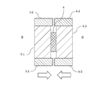
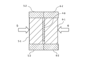
- the manufacturing method of the glass blank of 1st it is a schematic cross section explaining the other part of all the processes. In an example of the manufacturing method of the glass blank of 1st this embodiment, it is a schematic cross section explaining the other part of all the processes. In an example of the manufacturing method of the glass blank of 1st this embodiment, it is a schematic cross section explaining the other part of all the processes. In an example of the manufacturing method of the glass blank of 1st this embodiment, it is a schematic cross section explaining the other part of all the processes. In an example of the manufacturing method of the glass blank of 1st this embodiment, it is a schematic cross section explaining the other part of all the processes.
- the manufacturing method of the glass blank of 2nd this embodiment is shown, and it shows a mode that the molten glass flow
- the manufacturing method of the glass blank of 2nd this embodiment is shown, and a mode that the separated molten glass lump falls while rotating is shown.
- the manufacturing method of the glass blank of 2nd this embodiment is shown, and a mode that a molten glass lump falls while rotating between the opposing press-molding surfaces is shown.
- the manufacturing method of the glass blank of 2nd this embodiment is shown, Comprising:
- the press mold which shows the mode of the press start of a molten glass lump, and the vertical cross section of a molten glass lump are shown.
- the manufacturing method of the glass blank of 2nd this embodiment is shown, Comprising: It is the press mold which shows the process of extending a glass to a thin plate shape with a press, and the vertical cross section of glass.
- the manufacturing method of the glass blank of 2nd this embodiment is shown, Comprising: The vertical cross section of a press-molding die and a sheet glass when shape
- the manufacturing method of the glass blank of 2nd this embodiment is shown, Comprising: It is a vertical cross section of a press-molding die and a sheet glass which shows a mode that a sheet glass is cooled, making a press-molding surface follow a sheet glass.
- the manufacturing method of the glass blank of 2nd this embodiment is shown, and it is a vertical sectional view which shows a mode that a sheet glass is released from one side of a press molding surface.
- the manufacturing method of the glass blank of 2nd this embodiment is shown, and the mode that thin plate glass is taken out from a press-molding die is shown.
- the separation marks formed on the surface of the molten glass lump when separating the tip portion of the molten glass flow are the molding surface of the first press molding die and the molding surface of the second press molding die.
- the molten glass lump and the molding surface facing the separation mark are brought into contact with each other in a state facing at least one molding surface selected from the above, and one glass blank has one central hole. It is used for producing a magnetic recording medium substrate.
- the molten glass lump formed separately from the molten glass flow falls to form the first press mold and the second press mold.
- the separation marks formed on the surface of the molten glass lump at the time of separation face at least one of the molding surfaces.
- the molten glass lump is pressed and press-molded by the first press mold and the second press mold. That is, the press molding process is performed in a state where the separation mark that causes the shear mark faces at least one molding surface side. Therefore, the shear mark remaining on the glass blank is localized near the center of the glass blank.
- the shear mark is removed together with the central portion (center hole forming region) of the glass blank in order to form the center hole when the magnetic recording medium substrate is manufactured. For this reason, it is not necessary to secure a large grinding allowance and / or polishing allowance for removing the sheer mark, and the lapping process can be omitted or shortened.
- the volume of the molten glass lump used for producing one glass blank is preferably in the range of not more than twice the volume of one magnetic recording medium substrate from the viewpoint of glass utilization efficiency. A range of 3 times or less is more preferable.
- the glass blank is regarded as a disk shape, the diameter is ⁇ b, the thickness is tb, and the diameter of the magnetic recording medium substrate is ⁇ sub, one melted when the following equation (1) is satisfied. Two or more magnetic recording medium substrates cannot be produced from one glass blank equal to the volume of the glass lump. ⁇ Formula (1) ⁇ sub ⁇ 2> ⁇ b
- the volume Vgob of the molten glass block is neglected by the volume change of the glass due to the temperature change. It is equal to the volume of the glass blank, and is specifically represented by the following formula (2).
- Vgob ⁇ ⁇ ( ⁇ b / 2) 2 ⁇ tb Therefore, when the following formula (3) is satisfied, only one magnetic recording medium substrate can be produced from the volume of one molten glass lump and one glass blank.
- Formula (3) Vgob ⁇ ⁇ ⁇ sub 2 ⁇ tb
- the first press mold and the second press mold need only be arranged opposite to each other in the direction intersecting with the falling direction of the molten glass lump, but usually with respect to the falling direction of the molten glass lump. It is particularly preferable that they are arranged opposite to each other in the orthogonal direction.
- the first press mold and the second press mold will be described on the premise that they are opposed to each other in a direction orthogonal to the falling direction of the molten glass lump.
- the molten glass lump separated from the tip of the molten glass flow may fall between the first press mold and the second press mold without rotating and may be press molded, or Alternatively, after the momentary rotation or while rotating, the film may fall between the first press mold and the second press mold and may be press molded.
- the separation marks formed on the surface of the molten glass lump are the molten glass lump. It is necessary to be located on the side of the molten glass lump when it is separated from the tip of the molten glass stream.
- the molten glass lump is usually formed by separating the tip of the molten glass flow that continuously flows out downward in the vertical direction.
- a separation mark is formed on the upper surface of the molten glass lump immediately after being separated from the molten glass stream.
- the separation marks formed on the upper surface of the molten glass lump when separating the tip of the molten glass stream are the molding surface of the first press mold and the second press mold.
- the molten glass lump formed separately from the molten glass flow rotates. Therefore, when the molten glass lump falls and reaches between the molding surface of the first press mold and the molding surface of the second press mold, the molten glass lump is positioned on the upper surface of the molten glass lump during separation.
- the separation mark that has been moved moves to the side surface side of the molten glass lump and faces one of the molding surface sides. In this state, the molten glass lump is pressed from the horizontal direction and press-molded by the first press-molding die and the second press-molding die. That is, the press molding process is performed in a state where the separation mark that causes the shear mark faces one of the molding surfaces.
- the shear mark remaining on the glass blank is localized near the center of the glass blank.
- the shear mark can be removed together with the central portion (center hole forming region) of the glass blank in order to form the center hole when the magnetic recording medium substrate is manufactured. For this reason, it is not necessary to secure a large grinding allowance and / or polishing allowance for removing the sheer mark, and the lapping process can be omitted or shortened.
- the molten glass lump may be rotated so as to face either one of the molding surfaces.
- “the molten glass lump faces one of the molding surfaces” means that the separation mark existing on the surface of the molten glass lump just before the press molding step is (1) the center of the molten glass lump. Not only when the point is located on a straight line connecting the molding surface of the first press mold and the molding surface of the second press mold with the shortest distance. (2) Including the case where the straight line is located within a range of an angle of about 45 degrees or less starting from the center point of the molten glass block. The angle is preferably 30 degrees or less, and more preferably 15 degrees or less.
- the separation mark and the molding surface come into contact with each other at the time of press molding, and the molten glass lump is press-molded in this state, so that the shear mark is positioned at the substantially central portion of the glass blank.
- the surface of the molten glass block near the separation mark and the molding surface come into contact.
- the shear mark is positioned near the center of the glass blank.
- the aspect shown in the above (1) is most preferable from the viewpoint of allowing the shear mark to be present in the central portion of the glass blank or in the vicinity thereof more reliably.
- the tip of the molten glass flow is separated by crossing a pair of shear blades with the molten glass flow from a direction substantially perpendicular to the direction in which the molten glass flow hangs down.
- the shape of the blade portion of the shear blade is not particularly limited as long as it is a shape suitable for separation (cutting) of the tip portion of the molten glass flow, but any one shape selected from a V shape or a U shape It is preferable that
- the moving direction in which the pair of shear blades approach or separate from each other when forming the molten glass block and the movement direction in which the pair of press molds approach or separate from each other during press molding are horizontal surfaces. It is necessary to be substantially parallel. Specifically, the angle formed by these two moving directions in the horizontal plane needs to be 10 degrees or less, preferably 5 degrees or less, and most preferably 0 degrees. When the two moving directions are substantially parallel in the horizontal plane, the molten glass lump rotates, and when the separation trace moves from the upper surface of the molten glass lump to the side surface, immediately before the press molding step is performed.
- Patent Document 2 does not disclose any positional relationship on the horizontal plane in the two moving directions described above.
- FIG. 1 and 2 are schematic cross-sectional views illustrating an example of the glass blank manufacturing method according to the first embodiment. Specifically, the process of cutting the tip of the molten glass flow with a pair of shear blades.
- FIG. 1 shows a state before cutting the front end portion of the molten glass flow
- FIG. 2 shows a state before and after the end of cutting the front end portion of the molten glass flow.
- a molten glass flow 20 is vertically lowered from a glass outlet 12 provided at a lower end of a glass outflow pipe 10 whose upper end is connected to a molten glass supply source (not shown).
- the first shear blade (lower blade) 30 and the second shear blade (upper blade) 40 are melted on both sides of the molten glass flow 20, respectively. It arrange
- the lower blade 30 and the upper blade 40 are provided on the substantially plate-like main body portions 32 and 42 and the end portions of the main body portions 32 and 42, and the molten glass flows out continuously downward in the vertical direction. It has the blade parts 34 and 44 which cut
- the upper surface 34U of the blade portion 34 and the lower surface 44B of the blade portion 44 form a surface that substantially matches the horizontal plane, and the lower surface 34B of the blade portion 34 and the upper surface 44U of the blade portion 44 intersect with the horizontal plane. An inclined surface is formed.
- the lower blade 30 is provided on the lower surface 32B side of the main body portion 32 and extends from the main body portion 32 side to the blade portion 34 side, and at the time of cutting the molten glass flow 20, the blade portion 34 moves to the molten glass flow 20.
- a pressing member 36 that presses the distal end portion 22 in conjunction with the biting operation.
- the lower blade 30 and the upper blade 40 are arranged so that the upper surface 34U of the blade part 34 and the lower surface 44B of the blade part 44 are at substantially the same height with respect to the vertical direction.
- the pressing member 36 is a rod-shaped member that is detachably attached to the main body 32, and the main body 32 so as to be substantially parallel to the substantially plate-shaped main body 32. It is attached to the bottom of the.
- the main body portion 32 is provided with an attachment portion 38 for attaching the pressing member 36.
- the position of the tip 36A on the blade 34 side of the pressing member 36 is adjusted by exchanging the pressing member 36 with a different length, or by sliding the pressing member 36 in the horizontal direction with respect to the mounting portion 38. Is possible.
- the position of the distal end 36A of the pressing member 36 is a position farther from the central axis D than the position of the distal end 34A of the blade part 34 with reference to the central axis D of the glass outflow tube 10. It is adjusted within the range.
- the position of the tip 36A is out of this range, when the tip 22 is separated (cut), the pressing member 36 comes into contact with the tip 22 before the blade 34, and the separated tip 22 is separated.
- the pressing member 36 may be provided integrally with the main body portion 32 so as not to be detachable, and may have other shapes such as a plate shape in addition to a rod shape.
- the viscosity of the molten glass flow 20 is not particularly limited as long as the viscosity is suitable for separation of the tip portion 22 and press molding, but it is usually a constant value within a range of 500 dPa ⁇ s to 1050 dPa ⁇ s. Preferably it is controlled.
- the upper blade 34U and the lower surface 44B of the blade portion 44 are moved further by moving the lower blade 30 and the upper blade 40 in the directions of the arrow X1 and the arrow X2, respectively.
- the lower blade 30 and the upper blade 40 penetrate into the molten glass flow 20 to the vicinity of the central axis D, and the tip 22 is separated (cut) as a substantially spherical molten glass lump 24.
- separation marks (cut marks) 24 ⁇ / b> A are formed on the upper surface of the molten glass lump 24.
- the molten glass lump (pressed object) is completely separated from the tip part (pressed glass material to be pressed) 22 and / or the molten glass stream 20 where the tip 36A of the pressing member 36 is being separated substantially before and after the cutting.
- (Form glass material) 24 is brought into contact with the upper side surface and pressed.
- a direction perpendicular to the central axis D of the press-molded glass materials 22 and 24 that is parallel to the vertical direction in the figure, an arrow X1, an arrow The external force is applied from the direction intersecting the vertical direction so that the sum of the magnitudes of the force vectors acting in the X-axis direction parallel to X2 substantially exceeds zero.
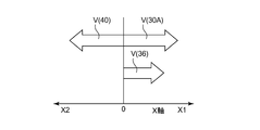
- FIGS. 3 and 4 are graphs for explaining an example of force vectors acting in the X-axis direction on the upper hemispheres of the press-molded glass materials 22 and 24.
- the horizontal axis means the X-axis direction, with the origin 0 as the starting point
- the right side direction represents the X1 direction that is the traveling direction of the lower blade 30 during cutting
- the left side direction is the cutting direction.
- This represents the X2 direction, which is the traveling direction of the upper blade 40 at the time.
- the vectors V (30A), V (40), and V (36) shown in FIGS. 3 and 4 are vectors derived from the lower blade 30, the upper blade 40, and the pressing member 36, that is, cutting. It means the force of the component acting in the X-axis direction among the three external forces caused by the lower blade 30, the upper blade 40 and the pressing member 36 applied to the upper part of the pressed glass materials 22 and 24 before and after.
- the two vectors V (30A) and V (40) resulting from the lower blade 30 and the upper blade 40 are vectors having opposite directions and substantially the same size.
- the magnitudes of the vectors of V (30A) and V (40) increase from 0 and show a maximum value.
- these two vectors V (30A) and V (40) are in a substantially canceling relationship in the molten glass lump forming process, and the difference in magnitude between V (30A) and V (40) is apparently substantially Thus, 0 is maintained.
- the vector V (36) may be applied only in the mode shown in FIG. 3 in which the lower blade 30 and the lower blade 40 are penetrating the molten glass flow 20. Then, the vector V (36) may be applied only in the embodiment shown in FIG. 4 after the lower blade 30 and the lower blade 40 have penetrated into the molten glass flow 20, and FIG. The vector V (36) may be applied in both of the modes shown in FIG.
- a pressing member 36 that is attached to the lower blade 30 and presses the upper side of the pressed glass materials 22 and 24 in conjunction with the lower blade 30 is used.
- the pressing member 36 that presses the pressed glass materials 22 and 24 may be disposed at a position separated from the lower blade 30 and the upper blade 40 to press the pressed glass materials 22 and 24.
- the pressing by the pressing member 36 causes the sum of the magnitudes of the force vectors acting in the X-axis direction of the pressed glass materials 22 and 24 to be substantially zero. If it is implemented so as to exceed, the pressing position and the pressing direction with respect to the pressed glass materials 22 and 24 can be arbitrarily selected.
- the lower side of the pressed glass materials 22 and 24 can be pressed in the horizontal direction by the pressing member 36.
- the case where the sum of the magnitudes of the force vectors acting in the X-axis direction of the pressed glass materials 22 and 24 does not substantially exceed 0 (in the vicinity of 0) is, for example, a molten glass flow
- a pair of shear blades are moved relative to the horizontal direction for the purpose of simply separating the tip portions 22 of the 20 so that the respective shear blades slide in the X1 direction and the X2 direction so that their surfaces slide. This means a case of moving at substantially the same speed. Further, as illustrated in FIGS.
- an external force that generates a force vector acting in the X-axis direction for the purpose of rotation is perpendicular to the pressed glass materials 22 and 24.
- the direction in which the external force is applied the direction in which the external force is applied, the position where the external force is applied to the press-molded glass materials 22 and 24, and the like are not particularly limited.
- the center point C of the press-molded glass materials 22 and 24 in the direction in which the external force is applied (however, the tip 22 before separation becomes a molten glass lump 24). It is particularly preferable that the center position) is not located.
- the application of external force to the pressed glass materials 22 and 24 for the purpose of rotating the molten glass lump 24 is performed by using the shape of the shear blade and the speed and timing of movement of the pair of shear blades instead of using the pressing member 36. It is also possible to control this.
- the contact time with respect to the upper surface of the tip portion (pressed glass material) 22 that is being separated from the lower surface 44B. are separated by providing a large number of protrusions on the long lower surface 34B, roughening the surface of the lower surface 34B, or coating the surface of the lower surface 34B with a material having higher wettability to the molten glass.
- the separation mark 24A located directly above the center point C of the molten glass lump 24 moves in the clockwise direction in FIG. It falls to the lower Y1 side in the vertical direction. And it enters between the 1st press-molding die and the 2nd press-molding die which are arranged oppositely in the direction orthogonal to drop direction Y1 of molten glass lump 24.
- the first press mold 50 and the second press mold 60 before the press molding are separated from each other so as to be line-symmetric with respect to the falling direction Y1. Are arranged.
- the molten glass lump 24 is pressed from both sides and press-molded in accordance with the timing when the molten glass lump 24 reaches the vicinity of the central portion in the vertical direction of the first press mold 50 and the second press mold 60. Therefore, the first press mold 50 moves in the arrow X1 direction, and the second press mold 60 moves in the arrow X2 direction.
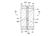
- the press molds 50 and 60 include press mold main bodies 52 and 62 having a substantially disk shape, and guide members 54 and 64 arranged so as to surround the outer peripheral ends of the press mold main bodies 52 and 62.
- FIG. 6 is a cross-sectional view, the guide members 54 and 64 are drawn on both sides of the press mold main bodies 52 and 62 in FIG.
- one surface of the press mold main bodies 52 and 62 is the molding surfaces 52A and 62A.
- the first press mold 50 and the second press mold 60 are opposed to each other so that the two molding surfaces 52A and 62A face each other.
- the guide member 54 is provided with a guide surface 54A at a height that slightly protrudes in the X1 direction with respect to the molding surface 52A, and the guide member 64 slightly protrudes in the X2 direction with respect to the molding surface 62A.
- a guide surface 64A is provided at the height position. For this reason, since the guide surface 54A and the guide surface 64A come into contact with each other during press molding, a gap is formed between the molding surface 52A and the molding surface 62A. For this reason, this gap thickness is the thickness of the molten glass lump 24 that is press-molded between the first press mold 50 and the second press mold 60, that is, the thickness of the glass blank. . As shown in FIG.
- the molding surfaces 52A and 62A are formed by forming the molten glass block 24 into the molding surface 52A of the first press mold 50 and the second press mold 60 by performing a press molding process.
- the sheet 62 is completely spread in the vertical direction and formed into a sheet glass, at least a region of the forming surfaces 52A and 62A that contacts the sheet glass forms a flat surface. Is formed.
- the heat resistance temperature of the metal or alloy constituting the press molds 50 and 60 is preferably 1000 ° C. or higher, and more preferably 1100 ° C. or higher.
- the materials constituting the press molds 50 and 60 are preferably spheroidal graphite cast iron (FCD), alloy tool steel (such as SKD61), high speed steel (SKH), cemented carbide, colmonoy, stellite, and the like.
- the glass blank is produced by pressing the molten glass lump 24 by pressing it with the molding surfaces 52A and 62A.
- the surface roughness of the molding surfaces 52A and 62A is substantially equal to the surface roughness of the main surface of the glass blank.
- the surface roughness (centerline surface roughness Ra) of the main surface of the glass blank is set to a range of 10 ⁇ m or less in performing scribing performed as a post-process described later and grinding using a diamond sheet. Therefore, it is preferable that the surface roughness of the press-molded surface (center line surface roughness Ra) is also in the range of 10 ⁇ m or less.
- the molten glass lump 24 shown in FIG. 6 falls further downward and enters between the two press molding surfaces 52A and 62A. Then, as shown in FIG. 7, when reaching the vicinity of the substantially central portion in the vertical direction of the press molding surfaces 52A and 62A that are parallel to the falling direction Y1, both side surfaces of the molten glass lump 24 are pressed with the press molding surfaces 52A, 62A is contacted. In this case, the separation mark 24A and the surface portion of the molten glass lump 24 that is point-symmetric with the separation mark 24A with respect to the center point C of the molten glass lump 24 are first formed into a press molding surface 62A and a press surface. It is preferable to contact 52A substantially simultaneously.
- the separation mark 24A starts from the center point C with respect to the straight line X3 that connects the center point C of the molten glass lump 24 and the press molding surface 62A at the shortest distance. It exists in the position which makes the angle of a degree.
- the molten glass lump 24 may fall while continuing to rotate until the start of press molding (hereinafter referred to as “rotation continuation type drop”). Further, an external force is applied from the direction intersecting the vertical direction so that the sum of the magnitudes of the force vectors acting in the X-axis direction on the pressed glass materials 22 and 24 substantially exceeds 0. When added, the molten glass lump 24 may drop while maintaining this state after instantaneously rotating until the start of press molding (hereinafter referred to as “rotation stop type drop”). . However, in any case, immediately before the press molding step shown in FIG. 7 is performed, as described above, the separation mark 24A has the center point C of the molten glass lump 24 with respect to the straight line X3. It is necessary to be within a range that forms an angle of 45 degrees or less (hereinafter sometimes referred to as “rotation angle”) as a starting point.
- the “fall distance” refers to the position where the separation mark 24A as illustrated in FIG. 2 is first formed, that is, the position where the lower blade 30 and the upper blade 40 overlap in the vertical direction in FIG. This means the position at the start of press molding as illustrated, that is, the distance to the vicinity of the central portion in the diameter direction of the press molding surfaces 52A and 62A that are parallel to the drop direction Y1.
- the drop distance is It is preferable to select within the range of 1000 mm or less, more preferable to select within the range of 500 mm or less, further preferable to select within the range of 300 mm or less, and most preferable to select within the range of 200 mm or less.
- the lower limit of the drop distance is not particularly limited, but is preferably 75 mm or more in practice.
- the following methods (1) and (2) can be adopted as a method of adjusting the rotation angle at the start of press molding within the above range.
- (1) The state of falling of the molten glass lump 24 in a state where the separation conditions of the molten glass lump 24 (for example, the drive timing of the shear blades 30 and 40) and the drive timing of the press molds 50 and 60 are constant. Monitor with a high-speed camera. Then, based on the monitoring result, the fall distance is adjusted so that the rotation angle at the start of press molding is within the above range.
- the state of falling of the molten glass block 24 is monitored with a high-speed camera in a state where the drop distance is constant. Then, based on the monitoring result, the separation conditions of the molten glass lump 24 (for example, the drive timing of the shear blades 30 and 40) are adjusted so that the rotation angle at the start of press molding is within the above range.
- temperatures of the first press mold 50 and the second press mold 60 at the start of press molding are preferably set to be lower than the glass transition temperature of the glass material constituting the molten glass lump 24.
- the thin glass 26 shown in FIG. 9 has substantially the same shape and thickness as the finally obtained glass blank.
- the time required for the guide surface 54A and the guide surface 64A shown in FIG. 9 to be in contact with each other from the state at the time of the start of press molding shown in FIG. 7 (hereinafter, referred to as “press molding time” may be referred to. ) Is preferably within 0.1 seconds from the viewpoint of thinning the molten glass lump 24.
- the guide surface 54A and the guide surface 64A are in contact with each other, so that it is easy to maintain the parallel state between the molding surface 52A and the molding surface 62A.
- the upper limit of press molding time is not specifically limited.
- the state in which the guide surface 54A and the guide surface 64A are in contact with each other is maintained, and the state in which both surfaces of the thin glass plate 26 and the molding surfaces 52A and 62A are in close contact is maintained.
- a pressure sufficiently smaller than the press pressure applied to the first press mold 50 and the second press mold 60 can be continuously applied. And this state is continued for several seconds, and the sheet glass 26 is cooled.
- the cooling of the thin glass 26 in a state of being sandwiched between the first press mold 50 and the second press mold 60 is carried out until it becomes below the yield point of the glass material constituting the thin glass 26. It is preferable to do.
- the press pressure is further increased in the state described above, the thin glass plate 26 may be damaged.
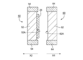
- the first press mold 50 is moved in the X2 direction so that the first press mold 50 and the second press mold 60 are separated from each other,
- the press mold 60 is moved in the X1 direction.
- the molding surface 62A and the thin glass plate 26 are released.
- the molding surface 52 ⁇ / b> A and the thin glass plate 26 are released, and the thin glass plate 26 is dropped to the lower side Y ⁇ b> 1 in the vertical direction and taken out.
- the mold can be released by shrinking the glass.
- extraction can be performed without applying a large force to the thin glass plate 26.
- the first press mold 50 and the second press mold 60 are cooled using a cooling medium such as water or air so that the temperatures of the molding surfaces 52A and 62A do not rise excessively. You may control to.
- the thin glass 26 taken out is annealed to reduce / remove the distortion, thereby obtaining a base material for processing the magnetic recording medium substrate, that is, a glass blank.
- the shear mark resulting from the separation mark 24A localizes in the central part vicinity of the main surface of this glass blank. For this reason, the region including the sheer mark can be removed by forming the center hole performed when the magnetic recording medium substrate is manufactured.
- the viscosity of the molten glass stream 20 is less than 500 dPa ⁇ s, it may be difficult to separate a necessary amount of the molten glass mass 24 in a state where the molten glass stream 20 is suspended in the air. For this reason, when the viscosity of the molten glass stream 20 is less than 500 dPa ⁇ s, the amount of molten glass required to support the tip 22 of the molten glass stream 20 below the glass outlet 12 and obtain the molten glass lump 24. Is accumulated, and then the molten glass block 24 is separated.
- the molten glass lump 24 thus obtained is dropped by applying an external force so that the molten glass lump 24 rotates with the center point C as a starting point, and the position of the separation mark 24A is the molding surface 52A.
- press molding may be started so as to face the molding surface 62A.
- the viscosity distribution of the molten glass lump 24 immediately before the start of press molding is made uniform, and the molten glass lump 24 is easily stretched thinly with an even thickness.
- the inner diameter of the center hole provided in the magnetic recording medium substrate is small, the size of the shear mark formed in the glass blank is reduced so that the shear mark is within the range where the center hole of the glass blank is formed.
- the cross-sectional shape in the vicinity of the tip 22 of the molten glass flow 20 in a plane orthogonal to the direction in which the molten glass flow 20 hangs has a substantially elliptical shape having a major axis and a minor axis. From the direction in which the separation of the tip portion 22 is substantially orthogonal to the direction in which the molten glass flow 20 hangs and substantially coincides with the major axis direction of the cross section near the tip portion 22 of the molten glass flow 20, It is effective to allow the pair of shear blades to penetrate from directions opposite to each other and intersecting the vertical direction. In this way, the shear mark can be reduced by separating the tip 22 of the molten glass flow 20.
- the shear mark can be localized within the range in which the center hole of the glass blank is formed.
- a method of elongating the opening shape of the glass outlet 12 or the direction in which the molten glass flow 20 is suspended A method of deforming so that the cross-sectional shape is elongated between both sides can be adopted.
- a method for reducing the shear mark a method of cutting the molten glass flow using a pair of shear blades whose blade portions are branched and whose shape is V-shaped or U-shaped is also effective.
- the separation of the tip portion 22 of the molten glass flow 20 is a pair of shear blades with respect to the molten glass flow 20 from a direction substantially perpendicular to the direction in which the molten glass flow 20 hangs down.
- 30 and 40 are made to penetrate from directions opposite to each other and intersecting with respect to the vertical direction.
- the size of the shear mark formed on the glass blank increases and decreases according to the inner peripheral length of the glass outlet 12. As the inner peripheral length of the glass outlet 12 increases, the size of the shear mark also increases, and as the inner peripheral length of the glass outlet 12 decreases, the size of the shear mark also decreases. Therefore, in order to make the size of the shear mark smaller than the center hole diameter, the inner peripheral length of the glass outlet 12 is reduced within a range where the outflow amount of the molten glass flow 20 per unit time becomes a predetermined amount, that is, the glass outlet 12. What is necessary is just to make the inside diameter of.
- the inner peripheral length of the glass outlet 12 is 47 mm (corresponding to an inner diameter of about 15 mm when the glass outlet 12 is circular).
- the outflow rate of the molten glass stream 20 is 500 g / min (for 50 glass blanks)
- the size of the shear mark is 18 mm, and the shear mark can be made smaller than the central hole diameter of 20 mm of the 2.5-inch size magnetic recording medium substrate.
- the viscosity of the molten glass flow 20 flowing out remains the above value and the inner peripheral length of the glass outlet 12 is 41 mm (corresponding to an inner diameter of about 13 mm)
- the outflow amount of the molten glass flow 20 per unit time is 350 g / min (for 35 glass blanks)
- the size of the sheer mark is 15 mm
- the sheer mark can be made smaller than the central hole diameter of 20 mm of the 2.5-inch size magnetic recording medium substrate. In this way, the size of the shear mark can be controlled so as to be within the center hole diameter of the magnetic recording medium substrate.
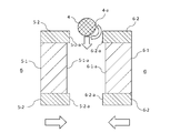
- FIG. 12 is a schematic cross-sectional view showing an example of separation of the front end portion of the molten glass flow by a pair of shear blades.
- FIG. 11 is a diagram showing a case where the cross section (horizontal cross section) of the molten glass flow 20 in a plane orthogonal to the central axis D in FIG.
- the alternate long and short dash line S means a direction in which the horizontal cross section coincides with the major axis direction of the molten glass flow 20 having an elliptical shape, and is parallel to the arrow X1 direction and the arrow X2 direction.
- FIG. 11 is a diagram showing a case where the cross section (horizontal cross section) of the molten glass flow 20 in a plane orthogonal to the central axis D in FIG.
- the alternate long and short dash line S means a direction in which the horizontal cross section coincides with the major axis direction of the molten glass flow 20 having an elliptical shape, and is parallel to the
- the glass blank manufacturing method of the first embodiment since a glass blank is manufactured using a horizontal direct press, a glass blank having a small thickness deviation and flatness can be easily obtained.
- the thickness deviation of the glass blank to be produced is preferably 10 ⁇ m or less, and the flatness is preferably 10 ⁇ m or less, more preferably 8 ⁇ m or less, further preferably 6 ⁇ m or less, and particularly preferably 4 ⁇ m or less.
- the glass blank manufacturing method of the first embodiment is suitable for manufacturing a glass blank having a ratio of diameter to plate thickness (diameter / plate thickness) of 50 to 150.
- the diameter is an arithmetic average of the major axis and the minor axis of the glass blank. Since the outer peripheral end surface of the glass blank is not restricted by the press molds 50 and 60, the outer peripheral end surface becomes a free surface.
- the roundness of the manufactured glass blank is not particularly limited, but is preferably within ⁇ 0.5 mm.
- the diameter of the glass blank there is no particular limitation on the diameter of the glass blank, but the setting of the diameter was performed by adding the removal amount at the time of scribe processing or outer periphery processing when processing the magnetic recording medium substrate from the glass blank to the substrate diameter as described later. It is preferable to carry out the value as a target.
- the thickness of the glass blank is preferably in the range of 0.75 to 1.1 mm, more preferably in the range of 0.75 to 1.0 mm.
- the thickness, thickness deviation, flatness, diameter, and roundness of the glass blank may be measured using a three-dimensional measuring instrument and a micrometer.
- composition of the glass to be used may be appropriately selected according to the properties required for the magnetic recording medium substrate, for example, aluminosilicate glass, soda lime glass, soda aluminosilicate glass, aluminoborosilicate glass, borosilicate glass, etc. Can be mentioned. These glasses may be crystallized glass that is crystallized by heat treatment, and may be processed into a magnetic recording medium substrate after being crystallized by heat treatment.
- glass used for a magnetic recording medium substrate used for manufacturing a magnetic recording medium such as a magnetic disk has chemical durability, high rigidity, and a high thermal expansion coefficient. Furthermore, when emphasizing increasing the bending strength, it is required to have a composition that can be chemically strengthened, and when performing high-temperature heat treatment during the manufacturing process of a magnetic recording medium, the composition has high heat resistance. It is desirable.
- Sn oxide and Ce oxide in the range of 0.1 to 3.5% by mass in terms of the total content of the outer oxide in order to improve the foaming at the time of clarification.
- the mass ratio of the Sn oxide content to the total content of Sn oxide and Ce oxide (Sn oxide mass / (Sn oxide mass + Ce oxide mass)) is 0.01 to 0.99.
- the content of glass components and the total content are expressed in mol%, but the contents of Sn oxide and Ce oxide are expressed in mass%.
- SiO 2 is a glass network-forming component and an essential component that functions to improve glass stability, chemical durability, and particularly acid resistance. If the content of SiO 2 is less than 50%, the above function cannot be obtained sufficiently, and if it exceeds 75%, undissolved matter is generated in the glass, or the viscosity of the glass at the time of clarification becomes too high, and the bubbles are blown out. It may be insufficient. Therefore, the content of SiO 2 is preferably 50 to 75%.
- Al 2 O 3 also contributes to the formation of a glass network, functions to improve glass stability and chemical durability, and also functions to increase the ion exchange rate during chemical strengthening. If the content of Al 2 O 3 exceeds 15%, the meltability of the glass is lowered, and undissolved substances are likely to be generated. In addition, the thermal expansion coefficient may decrease and the Young's modulus may decrease. Therefore, the content of Al 2 O 3 is preferably 0 to 15%.
- Li 2 O, Na 2 O and K 2 O serve to improve the meltability and formability of the glass. It also serves to increase the coefficient of thermal expansion. If the content of Li 2 O, Na 2 O and K 2 O is less than 3%, the above function may not be sufficiently obtained. If it exceeds 35%, chemical durability, particularly acid resistance may be lowered. The thermal stability of the glass may decrease. Moreover, a glass transition temperature may fall and heat resistance may also fall. Therefore, the content of Li 2 O, Na 2 O and K 2 O is preferably 3 to 35%, more preferably 5 to 35%. Of Li 2 O, Na 2 O and K 2 O, Li 2 O has the greatest effect of lowering the glass transition temperature.
- MgO, CaO, SrO, BaO and ZnO function to improve the meltability, moldability and Young's modulus of glass. It also functions to increase the thermal expansion coefficient and Young's modulus. However, if the total content of MgO, CaO, SrO, BaO and ZnO exceeds 35%, chemical durability and thermal stability of the glass may be lowered. Therefore, the total content of MgO, CaO, SrO, BaO and ZnO is preferably 0 to 35%.
- ZrO 2 , TiO 2 , La 2 O 3 , Y 2 O 3 , Ta 2 O 5 , Nb 2 O 5 and HfO 2 improve chemical durability, especially alkali resistance, increase glass transition temperature and heat resistance Improves the Young's modulus and fracture toughness.
- the total content of ZrO 2 , TiO 2 , La 2 O 3 , Y 2 O 3 , Ta 2 O 5 , Nb 2 O 5 and HfO 2 exceeds 15%, the melting property of the glass is lowered, In some cases, undissolved material of the glass raw material may remain. Therefore, the total content of ZrO 2 , TiO 2 , La 2 O 3 , Y 2 O 3 , Ta 2 O 5 , Nb 2 O 5 and HfO 2 is preferably 0 to 15%.
- composition range included in the above composition range is exemplified below.
- the content of glass components and the total content are expressed in mol% unless otherwise specified.
- the first glass emphasizes the efficiency of chemical strengthening, and its composition range is 1) SiO 2 content: 60-75%, 2) Al 2 O 3 content: 3-12%, 3) Total content of at least one metal oxide selected from Li 2 O, Na 2 O and K 2 O: 20 to 35% (preferably 20 to 30%), 4) Total content of at least one metal oxide selected from MgO, CaO, SrO, BaO and ZnO: 0-5%, and 5) ZrO 2 , TiO 2 , La 2 O 3 , Y 2 O 3 Total content of at least one metal oxide selected from Yb 2 O 3 , Ta 2 O 5 , Nb 2 O 5 and HfO 2 : 0 to 7% It is.
- the second glass emphasizes chemical durability, and its composition range is 1) SiO 2 content: 60-75%, 2) Al 2 O 3 content: 1-15%, 3) Total content of at least one metal oxide selected from Li 2 O, Na 2 O and K 2 O: 15-25%, 4) Total content of at least one metal oxide selected from MgO, CaO, SrO, BaO and ZnO: 1 to 6%, and 5) Total content of at least one metal oxide selected from ZrO 2 , TiO 2 , La 2 O 3 , Y 2 O 3 , Yb 2 O 3 , Ta 2 O 5 , Nb 2 O 5 and HfO 2 : 0.1 to 9% (preferably 0.5 to 9%, more preferably 1 to 9%), It is.
- the third glass emphasizes high rigidity, and its composition range is 1) SiO 2 content: 50-70%, 2) Al 2 O 3 content: 1-8%, 3) Total content of at least one metal oxide selected from Li 2 O, Na 2 O and K 2 O: 12-22%, 4) Total content of at least one metal oxide selected from MgO, CaO, SrO, BaO and ZnO: 10 to 20%, and 5) Total content of at least one metal oxide selected from ZrO 2 , TiO 2 , La 2 O 3 , Y 2 O 3 , Yb 2 O 3 , Ta 2 O 5 , Nb 2 O 5 and HfO 2 : 3-10% It is.
- the fourth glass emphasizes high heat resistance, and its composition range is 1) SiO 2 content: 50-70%, 2) Al 2 O 3 content: 1-10%, 3) Total content of at least one metal oxide selected from Li 2 O, Na 2 O and K 2 O: 5 to 17% (provided that the content of Li 2 O is 0 to 5%, preferably 0-1%), 4) Total content of at least one metal oxide selected from MgO, CaO, SrO, BaO and ZnO: 10 to 25%, 5) Total content of at least one metal oxide selected from ZrO 2 , TiO 2 , La 2 O 3 , Y 2 O 3 , Yb 2 O 3 , Ta 2 O 5 , Nb 2 O 5 and HfO 2 : 1-12%, It is.
- the fifth glass emphasizes high heat resistance, high rigidity, and high thermal expansion, and its composition range is 1) SiO 2 content: 50-75%, 2) Al 2 O 3 content: 0-5%, 3) Total content of at least one metal oxide selected from Li 2 O, Na 2 O and K 2 O: 3 to 15% (provided that the content of Li 2 O is 0 to 1%), 4) Total content of at least one metal oxide selected from MgO, CaO, SrO, BaO and ZnO: 14 to 35%, and 5) Total content of at least one metal oxide selected from ZrO 2 , TiO 2 , La 2 O 3 , Y 2 O 3 , Yb 2 O 3 , Ta 2 O 5 , Nb 2 O 5 and HfO 2 : 2-9% It is.
- the manufacturing method of the magnetic recording medium substrate of the first embodiment is a center hole forming step of forming a center hole in the central portion of the main surface of the glass blank produced by the glass blank manufacturing method of the first embodiment. And a magnetic recording medium substrate is manufactured through at least a polishing step of polishing the main surface.
- Scribe is a glass blank that is cut into two concentric circles (inner concentric circle and outer concentric circle) with a scriber made of super steel alloy or diamond particles on the surface of the glass blank in order to make the molded glass blank into a ring shape of a predetermined size. This refers to providing a line (linear scratch).
- the shear mark remaining on the glass blank is localized inside the inner concentric circle.
- the glass blank scribed in two concentric shapes is partially heated and the difference in the thermal expansion of the glass removes the outer portion of the outer concentric circle and the inner portion of the inner concentric circle. Thereby, it becomes a perfect circle shape and ring-shaped disk-shaped glass. Removal of the inner portion of the inner concentric circle corresponds to a center hole forming step for forming a center hole, and the shear mark is removed by this processing.
- a cutting line can be suitably provided using a scriber.
- a scriber may not follow surface unevenness
- Shape processing includes chamfering (chamfering of the outer peripheral end and the inner peripheral end). In chamfering, chamfering is performed on the outer peripheral end and inner peripheral end of the ring-shaped glass with a diamond grindstone.
- the end face of the disk-shaped glass is polished.
- the inner peripheral side end surface and the outer peripheral side end surface of the disk-shaped glass are mirror-finished by brush polishing.
- a slurry containing fine particles such as cerium oxide as free abrasive grains is used.
- polishing is given to the main surface of disk-shaped glass.
- the first polishing is intended to remove scratches and distortions remaining on the main surface.
- the machining allowance by the first polishing is, for example, about several ⁇ m to 10 ⁇ m.
- a double-side polishing apparatus is used.
- the double-side polishing apparatus is an apparatus that performs polishing by using a polishing pad and relatively moving a disk-shaped glass and a polishing pad.
- the double-side polishing apparatus includes a polishing carrier mounting portion having an internal gear and a sun gear that are driven to rotate at a predetermined rotation ratio, and an upper surface plate and a lower surface plate that are driven to rotate reversely with respect to the polishing carrier mounting portion.
- a polishing carrier mounting portion having an internal gear and a sun gear that are driven to rotate at a predetermined rotation ratio, and an upper surface plate and a lower surface plate that are driven to rotate reversely with respect to the polishing carrier mounting portion.
- Have A polishing pad, which will be described later, is attached to the surfaces of the upper and lower surface plates facing the disk-shaped glass.
- the polishing carrier mounted so as to mesh with the internal gear and the sun gear revolves around the sun gear while rotating around the sun gear.
- a plurality of disc-shaped glasses are held on each polishing carrier.
- the upper surface plate is movable in the vertical direction, and presses the polishing pad against the main surfaces of the front and back surfaces of the disk-shaped glass. Then, while supplying a slurry (polishing liquid) containing abrasive grains (polishing material), the planetary gear motion of the polishing carrier and the upper surface plate and the lower surface plate are rotated in reverse to each other, so that the disk-shaped glass and the polishing pad The main surfaces of the front and back surfaces of the disk-shaped glass are polished.
- a hard resin polisher is used as the polishing pad, and for example, cerium oxide abrasive grains are used as the abrasive.
- the disc-shaped glass after the first polishing is chemically strengthened.
- a molten salt used for chemical strengthening for example, a mixed molten salt of potassium nitrate (60% by mass) and sodium nitrate (40% by mass) can be used.
- the molten salt is heated to, for example, 300 ° C. to 400 ° C., and the washed disc-shaped glass is preheated to, for example, 200 ° C. to 300 ° C., and then the glass is placed in the molten salt, for example, 3 to 4 hours. Soaked.
- the immersion is preferably performed in a state of being housed in a holder so that a plurality of disk-shaped glasses are held at the end faces so that both main surfaces of the disk-shaped glass are chemically strengthened.
- the second polishing is applied to the disc-shaped glass that has been chemically strengthened and thoroughly cleaned.
- the machining allowance by the second polishing is, for example, about 1 ⁇ m.
- the second polishing is intended to finish the main surface into a mirror surface.
- the disc-shaped glass is polished using a double-side polishing apparatus.
- the polishing abrasive grains contained in the polishing liquid (slurry) to be used and the composition of the polishing pad Is different.
- the grain size of the abrasive grains to be used is made smaller than in the first polishing step, and the hardness of the polishing pad is made softer.
- a soft foamed resin polisher is used as the polishing pad, and for example, cerium oxide abrasive particles or colloidal silica finer than the cerium oxide abrasive particles used in the first polishing step are used as the abrasive.
- cerium oxide abrasive particles or colloidal silica finer than the cerium oxide abrasive particles used in the first polishing step are used as the abrasive.
- the disk-shaped glass polished in the second polishing process is washed again. In cleaning, a neutral detergent, pure water, and IPA are used.
- a magnetic disk glass substrate having a main surface flatness of 4 ⁇ m or less and a main surface roughness of 0.2 nm or less is obtained. Thereafter, each layer such as a magnetic layer is formed on the glass substrate for magnetic disk to produce a magnetic disk.
- the chemical strengthening step is performed between the first polishing step and the second polishing step, but is not limited to this order.
- a chemical strengthening process can be arrange
- the order of a) first polishing step, b) second polishing step, and c) chemical strengthening step (hereinafter may be referred to as “step order 1”) may be used.
- the process order 1 since the surface unevenness that may be generated by the chemical strengthening process is not removed, the process order performed in the order of a) the first polishing process, b) the chemical strengthening process, and c) the second polishing process. More preferable.
- the magnetic recording medium manufacturing method of the first embodiment is a magnetic recording layer forming method in which a magnetic recording layer is formed on a magnetic recording medium substrate produced by the magnetic recording medium substrate manufacturing method of the first embodiment.
- a magnetic recording medium is manufactured through at least the steps.
- a layer such as a magnetic layer is formed to form a magnetic recording medium substrate ( Magnetic disk).
- a magnetic recording medium substrate Magnetic disk
- an adhesion layer, a soft magnetic layer, a nonmagnetic underlayer, a perpendicular magnetic recording layer, a protective layer, and a lubricating layer are sequentially laminated from the main surface side of the substrate.
- a Cr alloy or the like is used for the adhesion layer and functions as an adhesion layer with the glass substrate.
- a CoTaZr alloy or the like is used for the soft magnetic layer
- a granular nonmagnetic layer or the like is used for the nonmagnetic underlayer
- a granular magnetic layer or the like is used for the perpendicular magnetic recording layer.
- a material made of hydrogen carbon is used for the protective layer, and a fluorine resin or the like is used for the lubricating layer, for example.
- an in-line sputtering apparatus is used on the glass substrate, and CrTi adhesion layer, CoTaZr / Ru / CoTaZr soft magnetic layer, and CoCrSiO 2 nonmagnetic granular layer are formed on both main surfaces of the glass substrate.
- a base layer, a CoCrPt—SiO 2 ⁇ TiO 2 granular magnetic layer, and a hydrogenated carbon protective film are sequentially formed.
- a perfluoropolyether lubricating layer is formed on the formed uppermost layer by a dip method to obtain a magnetic recording medium (magnetic disk).
- the method for producing a glass blank according to the second embodiment is a method of separating a molten glass lump from a molten glass flow flowing out from a glass outlet, press-molding a thin plate glass using a press mold, and magnetic recording having a center hole.
- the molten glass lump is separated and dropped, the molten glass lump in the air is pressed on the opposite pressing surface, and a thin glass is formed, And the direction of a molten glass lump is changed so that the site
- FIG. 13 a molten glass stream 2 flowing out from a glass outlet opening at the lower end of the glass outlet pipe 1 is suspended in the air.
- the molten glass stream 2 is cut by crossing the tips of the pair of shear blades 3-1 and 3-2 and shearing the glass.
- On the lower surface of the shear blade 3-1 there is provided a protrusion 3-1-a for applying the rotational torque by pushing the upper part of the molten glass block from the horizontal direction.
- the horizontal length of the protrusion 3-1-a can be adjusted.
- the outflow viscosity of the molten glass is controlled to be constant in the range of 500 dPa ⁇ s to 1050 dPa ⁇ s by adjusting the temperature of the glass outflow pipe 1.
- FIG. 14 shows the state of the moment when the tips of the shear blades 3-1 and 3-2 are crossed so that there is no gap, the lower part of the molten glass stream 2 is cut, and the molten glass lump 4 is separated. .
- the protrusion 3-1-a applies a torque for pushing the upper part of the molten glass lump 4 from the horizontal direction and rotating it clockwise. Note that the protrusion 3-1a is separated from the shear blade, and the upper portion of the molten glass lump 4 is pushed in the horizontal direction in synchronization with the movement of the shear blade 3-1, so that rotation torque is applied. You may make it rotate the molten glass lump 4 clockwise by pushing a lower part to a horizontal direction.
- FIG. 15 shows a state where the separated molten glass block falls while rotating clockwise.
- a shear mark by a shear blade so-called shear mark 4-a
- shear mark 4-a rotates in the horizontal direction.
- FIG. 16 shows a vertical cross section of the press molds 5 and 6.
- the press mold 5 is attached around the press mold body 5-1 having the press mold surface 5-1a and the press mold body 5-1, and the distance between the press mold surfaces is made of thin glass during press molding.
- the press mold body 5-1 is brought into contact with the press mold 6 so as to be equal to the plate thickness to determine the interval between the press mold surfaces and the main surface of the thin glass is followed by the press mold body 5-1.
- 1 is constituted by a guide member 5-2 for guiding 1.
- a metal or an alloy is preferable in consideration of heat resistance, workability, and durability.
- a metal or alloy having a heat resistant temperature of 1000 ° C. or higher, preferably 1100 ° C. or higher, when used as a press mold is more preferable.
- FCD spheroidal graphite cast iron
- SBD61 etc. alloy tool steel
- SHH high speed steel
- cemented carbide colmonoy, stellite, etc.
- the surface roughness of the main surface of the glass blank is desirably in the range of 0.01 to 10 ⁇ m when performing scribing and grinding using a diamond sheet, which will be described later. A range of 01 to 10 ⁇ m is preferable.
- the press mold 6 is attached around the press mold main body 6-1 having the press mold surface 6-1-a and the press mold main body 6-1.
- the press mold body 6-1 is brought into contact with the press mold 5 so as to be equal to the plate thickness to determine the interval between the press mold surfaces and the main surface of the thin glass is followed by the press mold body 6-1.
- 1 is constituted by a guide member 6-2 for guiding 1.
- FIG. 17 shows the moment when the molten glass lump 4 is started to be pressed by the press molding surfaces 5-1-a and 6-1-a.
- the shear mark 4-a is first in contact with the press molding surface 6-1-a.
- the drop distance is preferably 1000 mm or less so that the viscosity of the molten glass lump does not increase and does not deviate from the viscosity range suitable for press molding, and the drop speed does not increase and the position of the press does not fluctuate. , 500 mm or less, more preferably 300 mm or less, and even more preferably 200 mm or less.
- the glass When the surface of the molten glass block comes into contact with the press molding surface, it solidifies so as to stick to the press molding surface.
- the glass When the press is advanced, the glass is spread with a uniform thickness around the position where the molten glass lump and the press molding surface first contact each other, and is formed into a disk-like or substantially disk-like thin plate glass.
- FIG. 18 shows a state where the glass is spread out in the press process. Since the periphery of the shear mark first contacts with the press molding surface 6-1-a and is solidified so as to stick, it remains on the center surface of the thin glass.
- FIG. 19 shows the press molding surface 5-1-a and the press molding surface by contacting the abutting surface 5-1a of the guide member 5-1 and the abutting surface 6-1-a of the guide member 6-1.
- 6A shows a state in which the interval 6-1-a is defined as a distance corresponding to the thickness of the glass blank.
- the contact between the contact surface 5-1-a and the contact surface 6-1-a also serves to maintain the parallel state between the press molding surface 5-1-a and the press molding surface 6-1-a.
- the time from the start of pressing shown in FIG. 17 to the closing of the mold shown in FIG. 19 is preferably within 0.1 seconds in order to thin the molten glass lump.
- the press molding surfaces 5-1-a and 6-1-a are the main surfaces of the thin glass in a state where the contact surface 5-1a and the contact surface 6-1-a are in contact with each other.
- a pressure sufficiently lower than the press pressure is applied to the press mold main bodies 5-1 and 6-1 so as to maintain the state of being in close contact with the press. If the press pressure is increased in this state, the glass may be damaged. This state is continued for a few seconds to cool the thin glass.
- the press molds 5 and 6 are moved backward to release the thin glass 4-B from the press molding surface 6-1-a.
- the sheet glass 4-B is released from the press-molded surface 5-1a and taken out.
- the thin glass sheet taken out is annealed to reduce and remove strain, and a base material for processing a magnetic recording medium substrate, that is, a glass blank is obtained. Since the shear mark is localized at the center of the main surface of the glass blank, the region including the shear mark can be removed by center drilling when the substrate is manufactured.
- the cross-sectional shape of the molten glass flow is controlled so that the horizontal cross-section of the molten glass flow that hangs down is an elongated shape, that is, a cross-sectional shape having a major axis and a minor axis.
- the cross-sectional shape of the molten glass flow is elongated by elongating the shape of the glass outlet, or the cross-sectional shape is elongated by sandwiching the side surfaces of the molten glass flow from two opposing directions. And a molten glass flow is cut
- the shear mark By shearing the molten glass flow from the major axis direction, the shear mark can be reduced, and even when the inner diameter of the center hole is small, the shear mark can be localized within the range in which the center hole is provided.
- a method for reducing the shear mark a method of cutting a molten glass flow by intersecting a pair of shear blades having a V-shaped or U-shaped cutting blade is also effective.
- a glass blank having a thickness deviation of 10 ⁇ m or less and a flatness of 10 ⁇ m or less can be produced.
- a preferable range of the flatness of the glass blank is 8 ⁇ m or less, a more preferable range is 6 ⁇ m or less, and a further preferable range is 4 ⁇ m or less.
- the method for producing a glass blank according to the second embodiment is suitable for producing a glass blank having a ratio of diameter to plate thickness (diameter / plate thickness) of 50 to 150.
- the diameter is an arithmetic average of the major axis and the minor axis of the glass blank. Since the outer peripheral surface of the glass blank is not regulated by the press mold, the outer peripheral surface is a free surface, but the roundness of the formed glass blank is within ⁇ 0.5 mm.
- the diameter of the glass blank there is no particular limitation on the diameter of the glass blank, but the setting of the diameter is performed by adding the removal amount at the time of scribe processing and outer periphery processing when processing the magnetic recording medium substrate from the glass blank to the substrate diameter, as will be described later. It is preferable to carry out the above values.
- the plate thickness of the glass blank is in the range of 0.75 to 1.1 mm, preferably in the range of 0.75 to 1.0 mm, more preferably in the range of 0.90 to 0.92 mm.
- the thickness, thickness deviation, flatness, diameter, and roundness of the glass blank may be measured using a three-dimensional measuring instrument and a micrometer.
- composition of the glass to be used may be appropriately selected according to the properties required for the magnetic recording medium substrate, for example, aluminosilicate glass, soda lime glass, soda aluminosilicate glass, aluminoborosilicate glass, borosilicate glass, etc. Can be mentioned. These glasses may be crystallized glass that is crystallized by heat treatment, and may be processed into a substrate after being crystallized by heat treatment.
- glass used for a substrate of a magnetic recording medium such as a magnetic disk has chemical durability, high rigidity, and a high thermal expansion coefficient. Furthermore, when emphasizing increasing the bending strength, it is required to have a composition that can be chemically strengthened, and when high-temperature heat treatment is performed in the manufacturing process of a magnetic recording medium, the composition must have high heat resistance. Is desired.
- Sn oxide and Ce oxide in an externally divided total content of 0.1 to 3.5% by mass in order to improve the foaming at the time of clarification.
- the mass ratio of the Sn oxide content to the total content of Sn oxide and Ce oxide (Sn oxide mass / (Sn oxide mass + Ce oxide mass)) is 0.01 to 0. .99.
- the content of glass components and the total content are expressed in mol%, but the contents of Sn oxide and Ce oxide are expressed in mass%.
- SiO 2 is a glass network-forming component and an essential component that functions to improve glass stability, chemical durability, and particularly acid resistance. If the content of SiO 2 is less than 50%, the above function cannot be obtained sufficiently, and if it exceeds 75%, undissolved matter is generated in the glass, or the viscosity of the glass at the time of clarification becomes too high, and the bubbles are blown out. It becomes insufficient. Therefore, the content of SiO 2 is preferably 50 to 75%.
- Al 2 O 3 also contributes to the formation of a glass network, functions to improve glass stability and chemical durability, and also functions to increase the ion exchange rate during chemical strengthening.
- the content of Al 2 O 3 exceeds 15%, the meltability of the glass is lowered and undissolved substances are likely to be generated.
- the thermal expansion coefficient decreases and the Young's modulus also decreases. Therefore, the content of Al 2 O 3 is preferably 0 to 15%.
- Li 2 O, Na 2 O and K 2 O serve to improve the meltability and moldability of the glass. It also serves to increase the coefficient of thermal expansion. If the content of Li 2 O, Na 2 O and K 2 O is less than 3%, the above function cannot be obtained sufficiently, and if it exceeds 35%, chemical durability, particularly acid resistance is reduced, or glass The thermal stability of is reduced. Further, the glass transition temperature is lowered and the heat resistance is also lowered. Therefore, the content of Li 2 O, Na 2 O and K 2 O is preferably 3 to 35%, more preferably 5 to 35%. Of Li 2 O, Na 2 O, and K 2 O, Li 2 O has the greatest effect of lowering the glass transition temperature.
- MgO, CaO, SrO, BaO and ZnO function to improve the meltability, moldability and Young's modulus of glass. It also functions to increase the thermal expansion coefficient and Young's modulus. However, when the total content of MgO, CaO, SrO, BaO and ZnO exceeds 35%, chemical durability and thermal stability of the glass are lowered. Therefore, the total content of MgO, CaO, SrO, BaO and ZnO is preferably 0 to 35%.
- ZrO 2 , TiO 2 , La 2 O 3 , Y 2 O 3 , Ta 2 O 5 , Nb 2 O 5, and HfO 2 improve chemical durability, especially alkali resistance, increase glass transition temperature, and heat resistance Improves the Young's modulus and fracture toughness.
- the total content of ZrO 2 , TiO 2 , La 2 O 3 , Y 2 O 3 , Ta 2 O 5 , Nb 2 O 5 and HfO 2 exceeds 15%, the melting property of the glass is lowered, This leaves undissolved glass raw materials. Therefore, the total content of ZrO 2 , TiO 2 , La 2 O 3 , Y 2 O 3 , Ta 2 O 5 , Nb 2 O 5 and HfO 2 is preferably 0 to 15%.
- composition range included in the above composition range is exemplified below.
- the content of glass components and the total content are expressed in mol% unless otherwise specified.
- the first glass emphasizes the efficiency of chemical strengthening, and its composition range is SiO 2 content: 60-75%, Al 2 O 3 content: 3-12%, Total content of Li 2 O, Na 2 O and K 2 O: 20-35% (preferably 23-35%), Total content of MgO, CaO, SrO, BaO and ZnO: 0-5%, Total content of ZrO 2 , TiO 2 , La 2 O 3 , Y 2 O 3 , Yb 2 O 3 , Ta 2 O 5 , Nb 2 O 5 and HfO 2 : 0-7%, It is.
- the second glass emphasizes chemical durability, and its composition range is SiO 2 content: 60-75%, Al 2 O 3 content: 1 to 15%, Total content of Li 2 O, Na 2 O and K 2 O: 15-25%, Total content of MgO, CaO, SrO, BaO and ZnO: 1-6%, Total content of ZrO 2 , TiO 2 , La 2 O 3 , Y 2 O 3 , Yb 2 O 3 , Ta 2 O 5 , Nb 2 O 5 and HfO 2 : 0.1 to 9% (preferably 0.5 ⁇ 9%, more preferably 1-9%), It is.
- the third glass emphasizes high rigidity, and its composition range is SiO 2 content: 50-70%, Al 2 O 3 content: 1-8%, Total content of Li 2 O, Na 2 O and K 2 O: 12-22%, Total content of MgO, CaO, SrO, BaO and ZnO: 10-20%, Total content of ZrO 2 , TiO 2 , La 2 O 3 , Y 2 O 3 , Yb 2 O 3 , Ta 2 O 5 , Nb 2 O 5 and HfO 2 : 3 to 10%, It is.
- the fourth glass emphasizes high heat resistance, and its composition range is SiO 2 content: 50-70%, Al 2 O 3 content: 1-10%, Total content of Li 2 O, Na 2 O and K 2 O: 5 to 17% (Of which Li 2 O content: 0 to 5%, preferably 0 to 1%) Total content of MgO, CaO, SrO, BaO and ZnO: 10-25%, Total content of ZrO 2 , TiO 2 , La 2 O 3 , Y 2 O 3 , Yb 2 O 3 , Ta 2 O 5 , Nb 2 O 5 and HfO 2 : 1 to 12% It is.
- the fifth glass emphasizes high heat resistance, high rigidity, and high thermal expansion, and its composition range is SiO 2 content: 50-75%, Al 2 O 3 content: 0-5%, Total content of Li 2 O, Na 2 O and K 2 O: 3-15% (Of which Li 2 O content: 0 to 1%), Total content of MgO, CaO, SrO, BaO and ZnO: 14 to 35%, Total content of ZrO 2 , TiO 2 , La 2 O 3 , Y 2 O 3 , Yb 2 O 3 , Ta 2 O 5 , Nb 2 O 5 and HfO 2 : 2-9% It is.
- the manufacturing method of the magnetic recording medium substrate of the second embodiment includes a polishing step for polishing the main surface of the glass blank produced by the manufacturing method of the glass blank of the second embodiment, and a center at the center of the main surface.
- a magnetic recording medium substrate is manufactured through at least a hole forming step for forming holes.
- Scribe is a glass blank that is cut into two concentric circles (inner concentric circle and outer concentric circle) with a scriber made of super steel alloy or diamond particles on the surface of the glass blank in order to make the molded glass blank into a ring shape of a predetermined size. This refers to providing a line (linear scratch).
- the shear mark remaining on the glass blank is localized inside the inner concentric circle.
- the glass blank scribed in two concentric shapes is partially heated and the difference in the thermal expansion of the glass removes the outer portion of the outer concentric circle and the inner portion of the inner concentric circle. As a result, a perfect circular disk-shaped glass is obtained.
- the removal of the inner part of the inner concentric circle corresponds to the center drilling process, and the shear mark is removed by this process.
- a cutting line can be suitably provided using a scriber.
- the scriber does not follow the surface irregularities, and the cutting line cannot be provided uniformly. Therefore, scribing is performed after the main surface is smoothed.
- Shape processing includes chamfering (chamfering of the outer peripheral end and the inner peripheral end). In chamfering, chamfering is performed on the outer peripheral end and inner peripheral end of the ring-shaped glass with a diamond grindstone.
- the end face of the disk-shaped glass is polished.
- the inner peripheral side end surface and the outer peripheral side end surface of the glass are mirror-finished by brush polishing.
- a slurry containing fine particles such as cerium oxide as free abrasive grains is used.
- polishing is given to the main surface of disk-shaped glass.
- the first polishing is intended to remove scratches and distortions remaining on the main surface.
- the machining allowance by the first polishing is, for example, about several ⁇ m to 10 ⁇ m. Since it is not necessary to perform a grinding process with a large machining allowance, the glass is not scratched or distorted due to the grinding process. Therefore, the machining allowance in the first polishing process is small.
- a double-side polishing apparatus is used.
- the double-side polishing apparatus is an apparatus that performs polishing by using a polishing pad and relatively moving a disk-shaped glass and a polishing pad.
- the double-side polishing apparatus includes a polishing carrier mounting portion having an internal gear and a sun gear that are driven to rotate at a predetermined rotation ratio, and an upper surface plate and a lower surface plate that are driven to rotate reversely with respect to the polishing carrier mounting portion.
- a polishing carrier mounting portion having an internal gear and a sun gear that are driven to rotate at a predetermined rotation ratio, and an upper surface plate and a lower surface plate that are driven to rotate reversely with respect to the polishing carrier mounting portion.
- Have A polishing pad, which will be described later, is attached to the surfaces of the upper and lower surface plates facing the disk-shaped glass.
- the polishing carrier mounted so as to mesh with the internal gear and the sun gear revolves around the sun gear while rotating around the sun gear.
- a plurality of disc-shaped glasses are held on each polishing carrier.
- the upper surface plate is movable in the vertical direction, and presses the polishing pad against the main surfaces of the front and back surfaces of the disk-shaped glass. Then, while supplying a slurry (polishing liquid) containing abrasive grains (polishing material), the planetary gear motion of the polishing carrier and the upper surface plate and the lower surface plate are rotated in reverse to each other, so that the disk-shaped glass and the polishing pad The main surfaces of the front and back surfaces of the disk-shaped glass are polished.
- a hard resin polisher is used as the polishing pad, and for example, cerium oxide abrasive is used as the polishing material.
- the disc-shaped glass after the first polishing is chemically strengthened.
- the chemical strengthening liquid for example, a mixed liquid of potassium nitrate (60%) and sodium nitrate (40%) can be used.
- the chemical strengthening solution is heated to, for example, 300 ° C. to 400 ° C., and after the cleaned glass is preheated to, for example, 200 ° C. to 300 ° C., the glass is placed in the chemical strengthening solution, for example, 3 hours to 4 hours. Soaked.
- the immersion is preferably performed in a state of being housed in a holder so that a plurality of glasses are held at the end faces so that both main surfaces of the glass are chemically strengthened.
- second polishing is performed on the chemically strengthened and sufficiently cleaned glass.
- the machining allowance by the second polishing is, for example, about 1 ⁇ m.
- the second polishing is intended to finish the main surface into a mirror surface.
- the disc-shaped glass is polished using a double-side polishing apparatus.
- the polishing abrasive grains contained in the polishing liquid (slurry) to be used and the composition of the polishing pad Is different.
- the grain size of the abrasive grains to be used is made smaller than in the first polishing step, and the hardness of the polishing pad is made softer.
- a soft foamed resin polisher is used as the polishing pad, and as the abrasive, for example, cerium oxide abrasive grains finer than the cerium oxide abrasive grains used in the first polishing process are used.
- the disk-shaped glass polished in the second polishing process is washed again. In cleaning, a neutral detergent, pure water, and IPA are used.
- a magnetic disk glass substrate having a main surface flatness of 4 ⁇ m or less and a main surface roughness of 0.2 nm or less is obtained. Thereafter, each layer such as a magnetic layer is formed on the glass substrate for magnetic disk to produce a magnetic disk.
- the chemical strengthening step is performed between the first polishing step and the second polishing step, but is not limited to this order.
- a chemical strengthening process can be arrange
- the order of the first polishing process ⁇ the second polishing process ⁇ the chemical strengthening process (hereinafter, process order 1) may be used.
- the process order of the first polishing process ⁇ the chemical strengthening process ⁇ the second polishing process is more preferable.
- the magnetic recording medium manufacturing method of the second embodiment is a magnetic recording layer formation in which a magnetic recording layer is formed on a magnetic recording medium substrate produced by the magnetic recording medium substrate manufacturing method of the second embodiment.
- a magnetic recording medium is manufactured through at least the steps.
- the magnetic recording medium substrate is manufactured by forming a layer such as a magnetic layer on the main surface of the magnetic recording medium substrate (magnetic disk glass substrate) manufactured by the method described above.
- a layer such as a magnetic layer on the main surface of the magnetic recording medium substrate (magnetic disk glass substrate) manufactured by the method described above.
- an adhesion layer, a soft magnetic layer, a nonmagnetic underlayer, a perpendicular magnetic recording layer, a protective layer, and a lubricating layer are sequentially laminated from the main surface side of the substrate.
- a Cr alloy is used for the adhesion layer, and functions as an adhesion layer with the glass substrate.
- a CoTaZr alloy or the like is used for the soft magnetic layer
- a granular nonmagnetic layer or the like is used for the nonmagnetic underlayer
- a granular magnetic layer or the like is used for the perpendicular magnetic recording layer.
- a material made of hydrogen carbon is used for the protective layer, and a fluorine resin or the like is used for the lubricating layer, for example.
- an in-line sputtering apparatus is used on the glass substrate, and CrTi adhesion layer, CoTaZr / Ru / CoTaZr soft magnetic layer, and CoCrSiO 2 nonmagnetic granular layer are formed on both main surfaces of the glass substrate.
- a base layer, a CoCrPt—SiO 2 ⁇ TiO 2 granular magnetic layer, and a hydrogenated carbon protective film are sequentially formed.
- a perfluoropolyether lubricating layer is formed on the formed uppermost layer by a dip method to obtain a magnetic recording medium (magnetic disk).
- Example 1 Fabrication and evaluation of glass blanks-
- Raw materials such as oxides, carbonates, nitrates, and hydroxides were weighed so as to obtain a glass having the composition shown in Table 1, and mixed thoroughly to obtain a blended raw material.
- This raw material was put into a melting tank in a glass melting furnace, heated and melted, and the obtained molten glass was allowed to flow from the melting tank to the clarification tank and defoamed in the clarification tank. Furthermore, the molten glass was poured into the working tank, stirred and homogenized in the working tank, and was discharged from the glass outflow pipe attached to the bottom of the working tank.
- the temperature of the melting tank, clarification tank, working tank, and glass outflow pipe was controlled, and the temperature and viscosity of the molten glass were controlled within a predetermined range in each tank and glass outflow pipe.
- the molten glass flowing out from the glass outflow pipe was cast into a mold.
- the glass transition temperature and the liquidus temperature were measured using the obtained glass as a sample. The measuring method of glass transition temperature and liquidus temperature is shown below.
- Glass blanks were sequentially produced using glasses having the glass composition and characteristics shown in Table 1.
- the glass blank was produced by the method shown in FIGS. At this time, the viscosity of the molten glass stream 20 was adjusted to be constant in the range of 500 to 1050 dPa ⁇ s.
- the shape of the opening of the glass outlet 12 is an ellipse having a major axis of 28 mm and a minor axis of 8 mm, and the molten glass stream 20 is cut from the direction parallel to the major axis of the glass outlet 12 with the shapes of the blades 34 and 44 being V-shaped.
- the molten glass flow 20 depending on the pair of shear blades 30A and 40 was sheared.
- the press mold main bodies 52 and 62 and the guide members 54 and 64 constituting the press molds 50 and 60 are made of cast iron (FCD).
- the pressing pressure is lowered to keep the molding surfaces 52 ⁇ / b> A and 62 ⁇ / b> A in close contact with the thin glass 26 for several seconds, and the thin glass 26 is cooled.
- the thin glass shrinks during the cooling process, but the thin glass is cooled by maintaining the contact between the glass and the press molding surface by causing the press mold to follow the shrinkage of the thin glass.
- the press pressure is released, and as shown in FIGS. 10 and 11, the first press mold 50 and the second press mold 60 are separated from each other, and the thin glass 26, that is, the glass blank is released. And removed.
- the diameter, roundness, plate thickness, plate thickness deviation, and flatness of the obtained glass blank were measured using a three-dimensional measuring instrument and a micrometer. 1-No. In each of the glass blanks made of glass No. 6, the diameter was 75 mm, the roundness was within ⁇ 0.5 mm, the plate thickness was 0.90 mm, the plate thickness deviation was 10 ⁇ m or less, and the flatness was 4 ⁇ m or less. From the above measurement results, the diameter / plate thickness ratio was 83.3.
- the obtained glass blank was observed, a shear mark was observed at the center of one main surface. It was found that the shear mark was localized in a circle having a radius of 15 mm from the center of the glass blank, and could be completely removed when forming a central hole having an inner diameter of 20 mm in the production of the magnetic recording medium substrate.
- the obtained glass blank was annealed to reduce / remove strain.
- the disk-shaped glass was subjected to shape processing by chamfering or the like, and further subjected to end face polishing.
- the glass was immersed in a molten salt for chemical strengthening.
- the second glass was subjected to the second polishing on the thoroughly cleaned disc-shaped glass. After the second polishing step, the disk-shaped glass was washed again to produce a magnetic recording medium substrate.
- the magnetic recording medium substrate had an outer diameter of 65 mm, a center hole diameter of 20 mm, a thickness of 0.8 mm, a main surface flatness of 4 ⁇ m or less, and a main surface roughness of 0.2 nm or less.
- Example 1 A glass blank was produced in the same manner as in Example 1 except that the molten glass lump was separated using a butting type two blades that abutted the tips to cut the molten glass.
- the abutting type shear blade does not have a pressing member as provided in the shear blade used in the first embodiment.
- No. 1 shown in Table 1 was obtained. 1-No. In each of the glass blanks made of glass No.
- the diameter was 75 mm, the roundness was within ⁇ 0.5 mm, the plate thickness was 0.90 mm, the plate thickness deviation was 10 ⁇ m or less, and the flatness was 4 ⁇ m or less. From the above measurement results, the diameter / plate thickness ratio was 83.3.
- Example 2 In the same manner as in Example 1, a molten glass lump was separated using a cross type shear blade. Then, in the same manner as in Example 1 except that the press molding was performed in a state where the moving direction of the pair of shear blades and the moving direction of the pair of press molds in the horizontal plane were largely shifted from the substantially parallel state. A glass blank was produced. When the surface of the obtained glass blank was observed, the shear mark was formed in the peripheral part away from the center of the glass blank. Accordingly, the shear mark cannot be removed only by the center hole forming step.
- Example 3 A glass blank was produced in the same manner as in Example 1 except that the drop distance was changed to 100 mm. When the surface of the obtained glass blank was observed, the shear mark was formed in the peripheral part away from the center of the glass blank. Accordingly, the shear mark cannot be removed only by the center hole forming step.
- Example 4 A glass blank was produced in the same manner as in Example 1 except that the timings of driving the shear blades 30A, 40 and the press molds 50, 60 were shifted. When the surface of the obtained glass blank was observed, the shear mark was formed in the peripheral part away from the center of the glass blank. Accordingly, the shear mark cannot be removed only by the center hole forming step.
- Example 2 A glass blank is formed in the same manner as in Example 1 except that the shape of the opening of the glass outlet 12 is an ellipse having a major axis of 30 mm and a minor axis of 10 mm, and the shape of the opening is changed to be slightly larger than that of Example 1.
- the shear mark was in the center of the glass blank, but a part of the shear mark protruded from the range of the center hole formed in the center hole forming process. The shear mark could not be completely removed. However, the shear mark could be completely removed by performing the lapping process.
- the grinding amount in the lapping process was 30 ⁇ m, which is very small compared with 50 ⁇ m in Comparative Example 1.
- Example 1 Raw materials such as oxides, carbonates, nitrates, and hydroxides were weighed so as to obtain glasses having the compositions shown in Table 2, and mixed well to prepare mixed raw materials.
- This raw material is put into a melting tank in a glass melting furnace, heated and melted, the obtained molten glass is flowed from the melting tank to the clarification tank, defoamed in the clarification tank, and further poured into the work tank.
- the mixture was stirred and homogenized in the work tank, and flowed out of the glass outflow pipe attached to the bottom of the work tank.
- the temperature of the melting tank, clarification tank, work tank, and glass outflow pipe is controlled, and the temperature and viscosity of the glass are maintained in the optimum state in each step.
- the molten glass flowing out from the glass outflow pipe was cast into a mold.
- the glass transition temperature and the liquidus temperature were measured using the obtained glass as a sample. The measuring method of glass transition temperature and liquidus temperature is shown below.
- Glass blanks were produced sequentially using these glasses.
- the glass blank is produced by the method shown in FIGS.
- the outflow viscosity of the molten glass was adjusted to be constant in the range of 500 to 1050 dPa ⁇ s.
- the shape of the glass outlet is an ellipse having a major axis of 28 mm and a minor axis of 8 mm, and the molten glass stream is cut by shearing the molten glass stream suspended by a pair of V-shaped shear blades from a direction parallel to the major axis of the glass outlet. went.
- the press mold main bodies 5-1 and 6-1 and the guide members 5-1 and 6-1 were made of cast iron (FCD).
- the height of the press mold was adjusted so that the falling distance from when the molten glass lump was separated until it was pressed was within 200 mm.
- the time from the start of pressing to closing the mold was set to within 0.1 seconds, and the pressing pressure was set to about 6.7 MPa.
- the pressure is reduced and the glass is cooled while maintaining the state where both press-formed surfaces are in close contact with the glass for about several seconds.
- the press pressure is released, the press mold is retracted, the glass blank is released and removed.
- the press mold may be cooled using a cooling medium to suppress the temperature rise.
- the diameter was 75 mm
- the roundness was within ⁇ 0.5 mm
- the plate thickness was 0.90 mm
- the plate thickness deviation was 10 ⁇ m or less
- the flatness was 4 ⁇ m or less. From the above measurement result, the diameter / plate thickness ratio is 83.3.
- the shear mark is localized in a circle having a radius of 5 mm from the center of the glass blank, and is completely removed when a center hole having an inner diameter of 20 mm is formed.
- the glass blank is annealed to reduce and remove strain.
- Example 2 Using the glass blank produced in Example 1, a scribing process was performed on the part that becomes the outer periphery of the magnetic disk substrate and the part that becomes the central hole. By such processing, two concentric grooves are formed on the outer side and the outer side. Next, the scribed portion is partially heated to generate a crack along the scribed groove due to the difference in thermal expansion of the glass, and the outer and inner portions of the outer concentric circle are removed. As a result, a perfect circular disk-shaped glass is obtained. By this processing, the trace of the shea mark is completely removed.
- the disk-shaped glass was subjected to shape processing by chamfering or the like, and further subjected to end face polishing.
- the glass is immersed in a chemical strengthening solution and chemically strengthened.
- the glass that was sufficiently washed was subjected to the second polishing.
- the disk-shaped glass was washed again to produce a magnetic disk glass substrate.
- the substrate has an outer diameter of 65 mm, a center hole diameter of 20 mm, a thickness of 0.8 mm, a main surface flatness of 4 ⁇ m or less, and a main surface roughness of 0.2 nm or less.
- a recording medium substrate could be obtained.
- Example 3 On both main surfaces of the magnetic recording medium substrate (magnetic disk glass substrate) produced in Example 2, an in-line sputtering apparatus was used to sequentially deposit a CrTi adhesion layer, a CoTaZr / Ru / CoTaZr soft magnetic layer, and CoCrSiO. 2 non-magnetic granular underlayer, CoCrPt-SiO 2 ⁇ TiO 2 granular magnetic layer, hydrogenated carbon protective film, and a perfluoropolyether lubricating layer as a top layer by dip method to form a magnetic recording medium (Magnetic disk) was obtained.
- the magnetic disk thus obtained was incorporated into a hard disk drive and checked for operation, the expected performance was obtained.
Landscapes
- Chemical & Material Sciences (AREA)
- Engineering & Computer Science (AREA)
- Materials Engineering (AREA)
- Organic Chemistry (AREA)
- Manufacturing & Machinery (AREA)
- Manufacturing Of Magnetic Record Carriers (AREA)
Abstract
Description
第一の本発明のガラスブランクの製造方法は、連続的に流出する溶融ガラス流の先端部を分離して溶融ガラス塊を形成する溶融ガラス塊形成工程と、当該溶融ガラス塊形成工程を経た後に、下方へと落下する溶融ガラス塊を、溶融ガラス塊の落下方向に対して交叉する方向に対向配置された第一のプレス成形型および第二のプレス成形型によりプレス成形するプレス成形工程と、を少なくとも経てガラスブランクを製造し、プレス成形が、溶融ガラス流の先端部を分離する際に溶融ガラス塊表面に形成された分離痕が、第一のプレス成形型の成形面および第二のプレス成形型の成形面から選択される少なくとも一方の成形面に対向した状態で、溶融ガラス塊と、分離痕に対向する成形面とを接触させるように実施され、1枚のガラスブランクが、1枚の中心孔を有する磁気記録媒体基板を作製するために用いられることを特徴とする。
(1)溶融ガラス塊形成工程の実施中において、溶融ガラス塊として分離される溶融ガラス流の先端部、および、
(2)溶融ガラス塊形成工程の終了直後からプレス成形工程の開始直前までの期間において、落下中の溶融ガラス塊、
から選択される少なくとも一方の被プレス成形ガラス素材に、鉛直方向と平行を成す被プレス成形ガラス素材の中心軸に対して直交する方向に作用する力のベクトルの大きさの総和が、実質的に0を超えるように、鉛直方向に対して交叉する方向から外力を付与する外力付与工程を実施することが好ましい。
第二の本発明のガラスブランクの製造方法は、ガラス流出口から流出する溶融ガラス流から溶融ガラス塊を分離し、プレス成形型を用いて薄板ガラスをプレス成形し、中心孔を有する磁気記録媒体基板に加工するためのガラスブランクを作製するガラスブランクの製造方法において、溶融ガラス塊を分離、落下させ、空中の溶融ガラス塊を対向するプレス成形面でプレスし、薄板ガラスを成形すること、および、溶融ガラス流から分離した部位がプレス成形面を向くように溶融ガラス塊の向きを変え、プレスを開始すること、を特徴とする。
12 ガラス流出口
20 溶融ガラス流
22 先端部(被プレス成形ガラス素材)
24 溶融ガラス塊(被プレス成形ガラス素材)
24A 分離痕
26 薄板ガラス
30 下側ブレード(シアブレード)
32 本体部
32B (本体部の)下面
34 刃部
34A (刃部の)先端
34U (刃部の)上面
34B (刃部の)下面
36 押圧部材
36A (押圧部材の)先端
38 取付部
40 上側ブレード(シアブレード)
42 本体部
42B (本体部の)下面
44 刃部
44U (刃部の)上面
44B (刃部の)下面
50 第一のプレス成形型
52 プレス成形型本体
52A 成形面
54 ガイド部材
54A ガイド面
60 第二のプレス成形型
62 プレス成形型本体
62A 成形面
64 ガイド部材
64A ガイド面
2 溶融ガラス流
3-1、3-2 シアブレード
4 溶融ガラス塊
5、6 プレス成形型
5-1、5-2 プレス成形型本体
6-1、6-2 ガイド部材
[ガラスブランクの製造方法]
第一の本実施形態のガラスブランクの製造方法は、連続的に流出する溶融ガラス流の先端部を分離して溶融ガラス塊を形成する溶融ガラス塊形成工程と、当該溶融ガラス塊形成工程を経た後に、下方へと落下する上記溶融ガラス塊を、溶融ガラス塊の落下方向に対して交叉する方向に対向配置された第一のプレス成形型および第二のプレス成形型によりプレス成形するプレス成形工程と、を少なくとも経てガラスブランクを製造する。ここで、プレス成形は、溶融ガラス流の先端部を分離する際に上記溶融ガラス塊表面に形成された分離痕が、第一のプレス成形型の成形面および第二のプレス成形型の成形面から選択される少なくとも一方の成形面に対向した状態で、溶融ガラス塊と、分離痕に対向する成形面とを接触させるように実施され、1枚の上記ガラスブランクが、1枚の中心孔を有する磁気記録媒体基板を作製するために用いられることを特徴とする。
・式(1) φsub×2>φb
ガラスブランクの体積と等しく、具体的には、下式(2)で表される。
・式(2) Vgob=π×(φb/2)2×tb
よって、下式(3)を満たす場合には、1つの溶融ガラス塊の体積と1枚のガラスブランクからは、1枚の磁気記録媒体基板しか作製できないことになる。
・式(3) Vgob<π×φsub2×tb
(1)溶融ガラス塊24の分離条件(たとえば、シアブレード30,40の駆動タイミング)と、プレス成形型50、60の駆動タイミングとを一定とした状態で、溶融ガラス塊24の落下の様子を高速度カメラでモニターする。そして、このモニター結果を元に、プレス成形の開始時点における回転角が上記範囲内となるように、落下距離を調整する。
(2)落下距離を一定とした状態で溶融ガラス塊24の落下の様子を高速度カメラでモニターする。そして、このモニター結果を元に、プレス成形の開始時点における回転角が上記範囲内となるように、溶融ガラス塊24の分離条件(たとえば、シアブレード30,40の駆動タイミング)とを調整する。
酸化物基準に換算し、モル%表示にて、
1)SiO2を50~75%、
2)Al2O3を0~15%、
3)Li2O、Na2OおよびK2Oから選択される少なくとも1種の金属酸化物を合計で3~35%、
4)MgO、CaO、SrO、BaOおよびZnOから選択される少なくとも1種の金属酸化物を合計で0~35%、ならびに、
5)ZrO2、TiO2、La2O3、Y2O3、Ta2O5、Nb2O5およびHfO2から選択される少なくとも1種の金属酸化物を合計で0~15%含むガラスを例示することができる。
1)SiO2の含有量:60~75%、
2)Al2O3の含有量:3~12%、
3)Li2O、Na2OおよびK2Oから選択される少なくとも1種の金属酸化物の合計含有量:20~35%(好ましくは20~30%)、
4)MgO、CaO、SrO、BaOおよびZnOから選択される少なくとも1種の金属酸化物の合計含有量:0~5%、ならびに
5)ZrO2、TiO2、La2O3、Y2O3、Yb2O3、Ta2O5、Nb2O5およびHfO2から選択される少なくとも1種の金属酸化物の合計含有量:0~7%、
である。
1)SiO2の含有量:60~75%、
2)Al2O3の含有量:1~15%、
3)Li2O、Na2OおよびK2Oから選択される少なくとも1種の金属酸化物の合計含有量:15~25%、
4)MgO、CaO、SrO、BaOおよびZnOから選択される少なくとも1種の金属酸化物の合計含有量:1~6%、ならびに、
5)ZrO2、TiO2、La2O3、Y2O3、Yb2O3、Ta2O5、Nb2O5およびHfO2から選択される少なくとも1種の金属酸化物の合計含有量:0.1~9%(好ましくは0.5~9%、より好ましくは1~9%)、
である。
1)SiO2の含有量:50~70%、
2)Al2O3の含有量:1~8%、
3)Li2O、Na2OおよびK2Oから選択される少なくとも1種の金属酸化物の合計含有量:12~22%、
4)MgO、CaO、SrO、BaOおよびZnOから選択される少なくとも1種の金属酸化物の合計含有量:10~20%、ならびに、
5)ZrO2、TiO2、La2O3、Y2O3、Yb2O3、Ta2O5、Nb2O5およびHfO2から選択される少なくとも1種の金属酸化物の合計含有量:3~10%、
である。
1)SiO2の含有量:50~70%、
2)Al2O3の含有量:1~10%、
3)Li2O、Na2OおよびK2Oから選択される少なくとも1種の金属酸化物の合計含有量:5~17%(但し、Li2Oの含有量:0~5%、好ましくは0~1%)、
4)MgO、CaO、SrO、BaOおよびZnOから選択される少なくとも1種の金属酸化物の合計含有量:10~25%、
5)ZrO2、TiO2、La2O3、Y2O3、Yb2O3、Ta2O5、Nb2O5およびHfO2から選択される少なくとも1種の金属酸化物の合計含有量:1~12%、
である。
1)SiO2の含有量:50~75%、
2)Al2O3の含有量:0~5%、
3)Li2O、Na2OおよびK2Oから選択される少なくとも1種の金属酸化物の合計含有量:3~15%(但し、Li2Oの含有量:0~1%)、
4)MgO、CaO、SrO、BaOおよびZnOから選択される少なくとも1種の金属酸化物の合計含有量:14~35%、ならびに、
5)ZrO2、TiO2、La2O3、Y2O3、Yb2O3、Ta2O5、Nb2O5およびHfO2から選択される少なくとも1種の金属酸化物の合計含有量:2~9%、
である。
第一の本実施形態の磁気記録媒体基板の製造方法は、第一の本実施形態のガラスブランクの製造方法により作製されたガラスブランクの主表面の中央部に中心孔を形成する中心孔形成工程と、主表面を研磨する研磨工程と、を少なくとも経て、磁気記録媒体基板を製造することを特徴とする。
第一の本実施形態の磁気記録媒体の製造方法は、第一の本実施形態の磁気記録媒体基板の製造方法によりより作製された磁気記録媒体基板上に磁気記録層を形成する磁気記録層形成工程を少なくとも経て、磁気記録媒体を製造することを特徴とする。
[ガラスブランクの製造方法]
第二の本実施形態のガラスブランクの製造方法は、ガラス流出口から流出する溶融ガラス流から溶融ガラス塊を分離し、プレス成形型を用いて薄板ガラスをプレス成形し、中心孔を有する磁気記録媒体基板に加工するためのガラスブランクを作製するガラスブランクの製造方法において、溶融ガラス塊を分離、落下させ、空中の溶融ガラス塊を対向するプレス成形面でプレスし、薄板ガラスを成形すること、および、溶融ガラス流から分離した部位がプレス成形面を向くように溶融ガラス塊の向きを変え、プレスを開始すること、を特徴とする。
酸化物基準に換算し、モル%表示にて、
SiO2を50~75%、
Al2O3を0~15%、
Li2O、Na2O及びK2Oを合計で3~35%、
MgO、CaO、SrO、BaO及びZnOを合計で0~35%、及び
ZrO2、TiO2、La2O3、Y2O3、Ta2O5、Nb2O5及びHfO2を合計で0~15%含むガラスを例示することができる。
SiO2の含有量:60~75%、
Al2O3の含有量:3~12%、
Li2O、Na2O及びK2Oの合計含有量:20~35%(好ましくは23~35%)、
MgO、CaO、SrO、BaO及びZnOの合計含有量:0~5%、
ZrO2、TiO2、La2O3、Y2O3、Yb2O3、Ta2O5、Nb2O5及びHfO2の合計含有量:0~7%、
である。
SiO2の含有量:60~75%、
Al2O3の含有量:1~15%、
Li2O、Na2O及びK2Oの合計含有量:15~25%、
MgO、CaO、SrO、BaO及びZnOの合計含有量:1~6%、
ZrO2、TiO2、La2O3、Y2O3、Yb2O3、Ta2O5、Nb2O5及びHfO2の合計含有量:0.1~9%(好ましくは0.5~9%、より好ましくは1~9%)、
である。
SiO2の含有量:50~70%、
Al2O3の含有量:1~8%、
Li2O、Na2O及びK2Oの合計含有量:12~22%、
MgO、CaO、SrO、BaO及びZnOの合計含有量:10~20%、
ZrO2、TiO2、La2O3、Y2O3、Yb2O3、Ta2O5、Nb2O5及びHfO2の合計含有量:3~10%、
である。
SiO2の含有量:50~70%、
Al2O3の含有量:1~10%、
Li2O、Na2O及びK2Oの合計含有量:5~17%
(うちLi2Oの含有量:0~5%、好ましくは0~1%)、
MgO、CaO、SrO、BaO及びZnOの合計含有量:10~25%、
ZrO2、TiO2、La2O3、Y2O3、Yb2O3、Ta2O5、Nb2O5及びHfO2の合計含有量:1~12%、
である。
SiO2の含有量:50~75%、
Al2O3の含有量:0~5%、
Li2O、Na2O及びK2Oの合計含有量:3~15%
(うちLi2Oの含有量:0~1%)、
MgO、CaO、SrO、BaO及びZnOの合計含有量:14~35%、
ZrO2、TiO2、La2O3、Y2O3、Yb2O3、Ta2O5、Nb2O5及びHfO2の合計含有量:2~9%、
である。
第二の本実施形態の磁気記録媒体基板の製造方法は、第二の本実施形態のガラスブランクの製造方法により作製されたガラスブランクの主表面を研磨する研磨工程と、主表面の中央に中心孔を設ける孔開け工程と、を少なくとも経て、磁気記録媒体基板を製造することを特徴とする。
第2研磨工程で研磨されたディスク状ガラスは、再度洗浄される。洗浄では、中性洗剤、純水、IPAが用いられる。
第二の本実施形態の磁気記録媒体の製造方法は、第二の本実施形態の磁気記録媒体基板の製造方法によりより作製された磁気記録媒体基板上に磁気記録層を形成する磁気記録層形成工程を少なくとも経て、磁気記録媒体を製造することを特徴とする。
以下、実施例により第一の本発明をより詳細に説明するが、第一の本発明は以下の実施例に限られるものではない。
-ガラスブランクの作製および評価-
表1に示す組成のガラスが得られるように酸化物、炭酸塩、硝酸塩、水酸化物などの原料を秤量し、十分混合して調合原料とした。この原料をガラス溶解炉内の溶融槽内に投入し、加熱、溶融し、得られた溶融ガラスを溶融槽から清澄槽へと流して清澄槽内で脱泡を行った。さらに、溶融ガラスを、作業槽へと流して作業槽内で攪拌、均質化し、作業槽の底部に取り付けたガラス流出管から流出させた。溶融槽、清澄槽、作業槽、ガラス流出パイプはそれぞれ温度制御され、各槽およびガラス流出パイプにおいて溶融ガラスの温度・粘度を所定の範囲に制御した。ガラス流出管より流出する溶融ガラスを鋳型に鋳込み成形した。得られたガラスを試料として、ガラス転移温度、液相温度を測定した。ガラス転移温度と液相温度の測定方法を以下に示す。
各ガラスのガラス転移温度Tgを、熱機械分析装置(TMA)を用いて測定した。
(2)液相温度
白金ルツボにガラス試料を入れ、所定温度にて2時間保持し、炉から取り出し冷却後、結晶析出の有無を顕微鏡により観察し、結晶の認められない最低温度を液相温度(L.T.)とした。
各ガラスのガラス転移温度と液相温度とを表1に示す。

作製したガラスブランクを用い、磁気記録媒体基板の外周となる部分と中心孔となる部分にスクライブ加工を施した。こうした加工で、外側および内側に2つの同心円状の溝を形成した。次いで、スクライブ加工した部分を部分的に加熱して、ガラスの熱膨張の差異により、スクライブ加工した溝に沿ってクラックを発生させ、外側同心円の外側部分と内側部分とを除去した。これにより、真円形状かつリング状のディスク状ガラスを得た。そして、この加工によってシアマークが完全に除去された。
作製した磁気記録媒体基板の両主表面上に、インライン型スパッタリング装置を用いて、順に、CrTiの付着層、CoTaZr/Ru/CoTaZrの軟磁性層、CoCrSiO2の非磁性グラニュラー下地層、CoCrPt-SiO2・TiO2のグラニュラー磁性層、水素化カーボン保護膜を成膜し、最上層にディップ法によりパーフルオロポリエーテル潤滑層を成膜して磁気記録媒体(磁気ディスク)を得た。このようにして得た磁気ディスクをハードディスクドライブに組み込み、動作確認をしたところ所期の性能を得ることができた。
先端同士を突き当てて溶融ガラスを切断する突き当て式2枚ブレードを用いて溶融ガラス塊を分離した以外は実施例1と同様にしてガラスブランクを作製した。なお、上記突き当て式シアブレードには、実施例1で用いたシアブレードに設けられたような押圧部材はない。得られたガラスブランクの直径、真円度、板厚、板厚偏差、平坦度を三次元測定器、マイクロメータを用いて測定したところ、表1に示すNo.1~No.6のガラスからなるガラスブランクにおいて、いずれも直径は75mm、真円度は±0.5mm以内、板厚は0.90mm、板厚偏差は10μm以下、平坦度は4μm以下であった。なお、上記測定結果から、直径/板厚比は83.3であった。
実施例1と同様に、交差式シアブレードを使用し、溶融ガラス塊の分離を行った。そして、水平面における、一対のシアブレードの移動方向と、一対のプレス成形型の移動方向とを、略平行な状態から大幅にずらした状態でプレス成形を行った以外は実施例1と同様にしてガラスブランクを作製した。得られたガラスブランクの表面を観察したところ、シアマークがガラスブランクの中央から離れた周辺部に形成されていた。したがって、中心孔形成工程だけではシアマークを除去することができなかった。
落下距離を100mmに変更した以外は実施例1と同様にしてガラスブランクを作製した。得られたガラスブランクの表面を観察したところ、シアマークがガラスブランクの中央から離れた周辺部に形成されていた。したがって、中心孔形成工程だけではシアマークを除去することができなかった。
シアブレード30A、40の駆動およびプレス成形型50,60の駆動のタイミングをずらした以外は実施例1と同様にしてガラスブランクを作製した。得られたガラスブランクの表面を観察したところ、シアマークがガラスブランクの中央から離れた周辺部に形成されていた。したがって、中心孔形成工程だけではシアマークを除去することができなかった。
ガラス流出口12の開口部の形状を長径30mm、短径10mmの楕円状とし、実施例1と比べて、開口部の形状をやや大きめに変更した以外は、実施例1と同様にしてガラスブランクを作製した。得られたガラスブランクの表面を観察したところ、シアマークはガラスブランクの中央にあったものの、中心孔形成工程で形成する中心孔の範囲からシアマークの一部がはみ出しており、中心孔形成工程だけではシアマークを完全に除去することができなかった。しかしながら、ラッピング工程を実施することでシアマークを完全に除去することができた。なお、ラッピング工程における研削量は、比較例1の50μmと比べて非常に小さい30μmであった。
以下、実施例により第二の本発明をより詳細に説明するが、第二の本発明は以下の実施例に限られるものではない。
表2に示す組成のガラスが得られるように酸化物、炭酸塩、硝酸塩、水酸化物などの原料を秤量し、十分混合して調合原料とした。この原料をガラス溶解炉内の溶融槽内に投入し、加熱、溶融し、得られた溶融ガラスを溶融槽から清澄槽へと流して清澄槽内で脱泡を行い、さらに作業槽へと流して作業槽内で攪拌、均質化し、作業槽の底部に取り付けたガラス流出管から流出した。溶融槽、清澄槽、作業槽、ガラス流出パイプはそれぞれ温度制御され、各工程においてガラスの温度、粘度が最適状態に保たれる。ガラス流出管より流出する溶融ガラスを鋳型に鋳込み成形した。得られたガラスを試料として、ガラス転移温度、液相温度を測定した。ガラス転移温度と液相温度の測定方法を以下に示す。
各ガラスのガラス転移温度Tgを、熱機械分析装置(TMA)を用いて測定した。
(2)液相温度
白金ルツボにガラス試料を入れ、所定温度にて2時間保持し、炉から取り出し冷却後、結晶析出の有無を顕微鏡により観察し、結晶の認められない最低温度を液相温度(L.T.)とした。
各ガラスのガラス転移温度と液相温度を表2に示す。
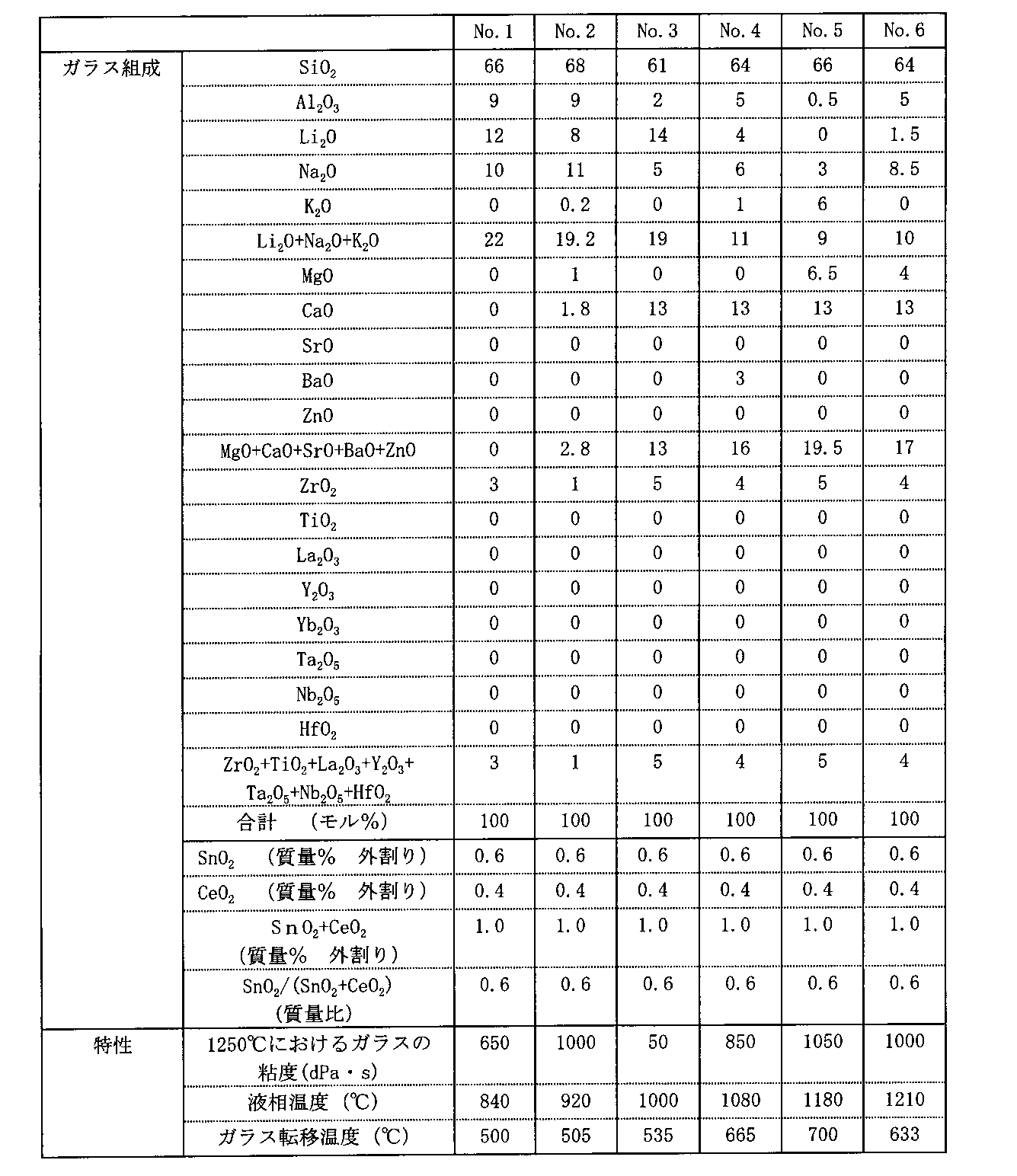
実施例1において作製したガラスブランクを用い、磁気ディスク基板の外周となる部分と中心孔になる部分にスクライブ加工を施した。こうした加工で、外側および外側に2つの同心円状の溝を形成する。次いで、スクライブ加工した部分を部分的に加熱して、ガラスの熱膨張の差異により、スクライブ加工した溝に沿ってクラックを発生させ、外側同心円の外側部分と内側部分とが除去される。これにより、真円形状のディスク状ガラスとなる。この加工によってシアマークの痕跡が完全に除去される。
実施例2において作製した磁気記録媒体基板(磁気ディスク用ガラス基板)の両主表面上に、インライン型スパッタリング装置を用いて、順に、CrTiの付着層、CoTaZr/Ru/CoTaZrの軟磁性層、CoCrSiO2の非磁性グラニュラー下地層、CoCrPt-SiO2・TiO2のグラニュラー磁性層、水素化カーボン保護膜を成膜し、最上層にディップ法によりパーフルオロポリエーテル潤滑層を成膜して磁気記録媒体(磁気ディスク)を得た。このようにして得た磁気ディスクをハードディスクドライブに組み込み、動作確認をしたところ所期の性能を得ることができた。
Claims (8)
- 連続的に流出する溶融ガラス流の先端部を分離して溶融ガラス塊を形成する溶融ガラス塊形成工程と、
当該溶融ガラス塊形成工程を経た後に、下方へと落下する上記溶融ガラス塊を、上記溶融ガラス塊の落下方向に対して交叉する方向に対向配置された第一のプレス成形型および第二のプレス成形型によりプレス成形するプレス成形工程と、を少なくとも経てガラスブランクを製造し、
上記プレス成形が、
上記溶融ガラス流の先端部を分離する際に上記溶融ガラス塊表面に形成された分離痕が、上記第一のプレス成形型の成形面および上記第二のプレス成形型の成形面から選択される少なくとも一方の成形面に対向した状態で、上記溶融ガラス塊と、上記分離痕に対向する成形面とを接触させるように実施され、
1枚の上記ガラスブランクが、1枚の中心孔を有する磁気記録媒体基板を作製するために用いられることを特徴とするガラスブランクの製造方法。 - 請求項1に記載のガラスブランクの製造方法において、
前記溶融ガラス塊が、鉛直方向の下方側へと連続的に流出する溶融ガラス流の先端部を分離することにより形成され、
前記プレス成形工程において、前記溶融ガラス流の先端部を分離する際に前記溶融ガラス塊の上部表面に形成された分離痕が、前記第一のプレス成形型の成形面および前記第二のプレス成形型の成形面から選択されるいずれか一方の成形面に対向した状態で、前記溶融ガラス塊と、前記分離痕に対向する成形面とを接触させることができるように、前記溶融ガラス塊を回転させるために、
(1)前記溶融ガラス塊形成工程の実施中において、前記溶融ガラス塊として分離される前記溶融ガラス流の先端部、および、
(2)前記溶融ガラス塊形成工程の終了直後から前記プレス成形工程の開始直前までの期間において、落下中の前記溶融ガラス塊、
から選択される少なくとも一方の被プレス成形ガラス素材に、鉛直方向と平行を成す上記被プレス成形ガラス素材の中心軸に対して直交する方向に作用する力のベクトルの大きさの総和が、実質的に0を超えるように、鉛直方向に対して交叉する方向から外力を付与する外力付与工程を実施することを特徴とするガラスブランクの製造方法。 - 請求項2に記載のガラスブランクの製造方法において、
前記溶融ガラス流の垂下する方向と直交する平面における前記溶融ガラス流の先端部近傍の断面の形状が、長径と短径とを有する略楕円形状を成し、
前記溶融ガラス流の先端部の分離が、前記溶融ガラス流の垂下する方向と略直交し、かつ、前記溶融ガラス流の先端部近傍の断面の長径方向と略一致する方向から、前記溶融ガラス流に対して、一対のシアブレードを互いに反対方向かつ鉛直方向に対して交叉する方向から貫入させることにより実施されることを特徴とするガラスブランクの製造方法。 - 請求項2または3に記載のガラスブランクの製造方法において、
前記溶融ガラス流の先端部の分離が、前記溶融ガラス流の垂下する方向と略直交する方向から、前記溶融ガラス流に対して、一対のシアブレードを互いに反対方向かつ鉛直方向に対して交叉する方向から貫入させることにより実施され、
上記一対のシアブレードの刃部が分岐し、その形状がV字形状およびU字形状から選択されるいずれか一方の形状であることを特徴とするガラスブランクの製造方法。 - 請求項1~4のいずれか1つに記載のガラスブランクの製造方法において、
前記プレス成形工程を実施する直前の前記溶融ガラス塊の表面に存在する前記分離痕が、
前記溶融ガラス塊の中心点と、前記第一のプレス成形型の成形面および前記第二のプレス成形型の成形面から選択されるいずれか一方の成形面と、を最短距離で結ぶ直線上に位置していることを特徴とするガラスブランクの製造方法。 - 請求項1~5のいずれか1つに記載のガラスブランクの製造方法において、
前記プレス成形工程の実施により、前記溶融ガラス塊が、前記第一のプレス成形型の成形面と前記第二のプレス成形型の成形面との間で完全に押広げられて板状ガラスに成形された際に、
前記第一のプレス成形型および前記第二のプレス成形型の成形面の少なくとも上記板状ガラスと接触する領域が、平坦面を形成していることを特徴とするガラスブランクの製造方法。 - 連続的に流出する溶融ガラス流の先端部を分離して溶融ガラス塊を形成する溶融ガラス塊形成工程と、
当該溶融ガラス塊形成工程を経た後に、下方へと落下する上記溶融ガラス塊を、上記溶融ガラス塊の落下方向に対して交叉する方向に対向配置された第一のプレス成形型および第二のプレス成形型によりプレス成形するプレス成形工程と、を少なくとも経てガラスブランクを製造した後、さらに、
上記ガラスブランクの主表面の中央部に中心孔を形成する中心孔形成工程と、
上記主表面を研磨する研磨工程と、
を少なくとも経て、1枚の上記ガラスブランクから1枚の磁気記録媒体基板を製造し、
上記プレス成形が、
上記溶融ガラス流の先端部を分離する際に上記溶融ガラス塊表面に形成された分離痕が、上記第一のプレス成形型の成形面および上記第二のプレス成形型の成形面から選択される少なくとも一方の成形面に対向した状態で、上記溶融ガラス塊と、上記分離痕に対向する成形面とを接触させるように実施されることを特徴とする磁気記録媒体基板の製造方法。 - 連続的に流出する溶融ガラス流の先端部を分離して溶融ガラス塊を形成する溶融ガラス塊形成工程と、
当該溶融ガラス塊形成工程を経た後に、下方へと落下する上記溶融ガラス塊を、上記溶融ガラス塊の落下方向に対して交叉する方向に対向配置された第一のプレス成形型および第二のプレス成形型によりプレス成形するプレス成形工程と、を少なくとも経てガラスブランクを製造し、さらに、
上記ガラスブランクの主表面の中央部に中心孔を形成する中心孔形成工程と、
上記主表面を研磨する研磨工程と、
を少なくとも経て、1枚の上記ガラスブランクから1枚の磁気記録媒体基板を製造した後に、
上記磁気記録媒体基板の主表面上に磁気記録層を形成する磁気記録層形成工程を少なくとも経て、磁気記録媒体を製造し、
上記プレス成形が、
上記溶融ガラス流の先端部を分離する際に上記溶融ガラス塊表面に形成された分離痕が、上記第一のプレス成形型の成形面および上記第二のプレス成形型の成形面から選択される少なくとも一方の成形面に対向した状態で、上記溶融ガラス塊と、上記分離痕に対向する成形面とを接触させるように実施されることを特徴とする磁気記録媒体の製造方法。
Priority Applications (4)
| Application Number | Priority Date | Filing Date | Title |
|---|---|---|---|
| SG2012070777A SG184234A1 (en) | 2010-03-31 | 2011-03-11 | Method for producing glass blank, method for producing magnetic recording medium substrate, and method for producing magnetic recording medium |
| PH1/2012/501892A PH12012501892A1 (en) | 2010-03-31 | 2011-03-11 | Method for manufacturing glass blank, method for manufacturing magnetic recording medium substrate and method for manufacturing magnetic recording medium |
| CN201180013357.8A CN102791642B (zh) | 2010-03-31 | 2011-03-11 | 玻璃坯料的制造方法、磁记录介质基板的制造方法以及磁记录介质的制造方法 |
| JP2012508193A JP5499159B2 (ja) | 2010-03-31 | 2011-03-11 | ガラスブランクの製造方法、磁気記録媒体基板の製造方法および磁気記録媒体の製造方法 |
Applications Claiming Priority (4)
| Application Number | Priority Date | Filing Date | Title |
|---|---|---|---|
| JP2010083725 | 2010-03-31 | ||
| JP2010-083725 | 2010-03-31 | ||
| JP2010-224029 | 2010-10-01 | ||
| JP2010224029 | 2010-10-01 |
Publications (1)
| Publication Number | Publication Date |
|---|---|
| WO2011122303A1 true WO2011122303A1 (ja) | 2011-10-06 |
Family
ID=44712026
Family Applications (1)
| Application Number | Title | Priority Date | Filing Date |
|---|---|---|---|
| PCT/JP2011/055753 Ceased WO2011122303A1 (ja) | 2010-03-31 | 2011-03-11 | ガラスブランクの製造方法、磁気記録媒体基板の製造方法および磁気記録媒体の製造方法 |
Country Status (7)
| Country | Link |
|---|---|
| US (1) | US20110283739A1 (ja) |
| JP (1) | JP5499159B2 (ja) |
| CN (1) | CN102791642B (ja) |
| MY (1) | MY156953A (ja) |
| PH (1) | PH12012501892A1 (ja) |
| SG (1) | SG184234A1 (ja) |
| WO (1) | WO2011122303A1 (ja) |
Cited By (3)
| Publication number | Priority date | Publication date | Assignee | Title |
|---|---|---|---|---|
| WO2013147149A1 (ja) * | 2012-03-30 | 2013-10-03 | Hoya株式会社 | 磁気ディスク用ガラスブランクの製造方法および磁気ディスク用ガラス基板の製造方法 |
| WO2014103295A1 (ja) * | 2012-12-27 | 2014-07-03 | Hoya株式会社 | ハードディスク用ガラス基板の製造方法 |
| JPWO2014046240A1 (ja) * | 2012-09-20 | 2016-08-18 | Hoya株式会社 | 磁気ディスク用ガラスブランクの製造方法、磁気ディスク用ガラス基板の製造方法、及び磁気ディスク用ガラスブランク |
Families Citing this family (3)
| Publication number | Priority date | Publication date | Assignee | Title |
|---|---|---|---|---|
| US8806895B2 (en) * | 2010-12-09 | 2014-08-19 | Hoya Corporation | Manufacturing method for a glass substrate for magnetic disk |
| JP2012160252A (ja) | 2011-01-31 | 2012-08-23 | Hoya Corp | 磁気ディスク用ガラス基板の製造方法 |
| US8931308B2 (en) * | 2011-02-10 | 2015-01-13 | Hoya Corporation | Method of producing glass blank for substrate of information recording medium, substrate for information recording medium, and information recording medium; and manufacturing apparatus for glass blank for substrate of information recording medium |
Citations (3)
| Publication number | Priority date | Publication date | Assignee | Title |
|---|---|---|---|---|
| JPH05221663A (ja) * | 1992-02-07 | 1993-08-31 | Olympus Optical Co Ltd | 軟化ガラスの供給方法および装置 |
| JP2003054965A (ja) * | 2001-08-08 | 2003-02-26 | Minolta Co Ltd | ガラスのプレス成形方法および該方法を用いたハードディスク用ガラス基板の製造方法 |
| JP4380379B2 (ja) * | 2004-03-19 | 2009-12-09 | コニカミノルタオプト株式会社 | 情報記録媒体用ガラス基板の製造方法 |
Family Cites Families (12)
| Publication number | Priority date | Publication date | Assignee | Title |
|---|---|---|---|---|
| US2812619A (en) * | 1954-04-05 | 1957-11-12 | Emhart Mfg Co | Glass feeder shears provided with charge turning mechanism |
| US3130028A (en) * | 1959-05-26 | 1964-04-21 | Pittsburgh Plate Glass Co | Glass feeding |
| US3130029A (en) * | 1959-06-23 | 1964-04-21 | Bausch & Lomb | Method for making fused multifocal lenses |
| BE758285A (fr) * | 1969-10-30 | 1971-04-30 | Corning Glass Works | Ciseaux de decoupe d'une paraison |
| JPS5219209B2 (ja) * | 1973-05-15 | 1977-05-26 | ||
| US4015967A (en) * | 1976-03-31 | 1977-04-05 | Owens-Illinois, Inc. | Method for shearing and turning the glass gob |
| US6626010B1 (en) * | 1999-10-19 | 2003-09-30 | Hoya Corporation | Method for floating glass lump, method for preparing glass lump and method for preparing molded glass, and apparatus used for the methods |
| JP2001302259A (ja) * | 2000-04-18 | 2001-10-31 | Asahi Techno Glass Corp | ガラス成形体とその製造方法およびガラス基板の製造方法 |
| CN1175401C (zh) * | 2000-04-28 | 2004-11-10 | 三井金属矿业株式会社 | 磁记录介质用玻璃基板的制造方法 |
| JP2004288228A (ja) * | 2003-01-31 | 2004-10-14 | Hoya Corp | 情報記録媒体用基板、情報記録媒体およびその製造方法 |
| US7395679B2 (en) * | 2004-03-19 | 2008-07-08 | Konica Minolta Opto, Inc. | Method of manufacturing glass substrate for information recording medium |
| SG177343A1 (en) * | 2009-12-29 | 2012-02-28 | Hoya Corp | Glass substrate for magnetic disk and manufacturing method thereof |
-
2011
- 2011-03-11 WO PCT/JP2011/055753 patent/WO2011122303A1/ja not_active Ceased
- 2011-03-11 CN CN201180013357.8A patent/CN102791642B/zh not_active Expired - Fee Related
- 2011-03-11 PH PH1/2012/501892A patent/PH12012501892A1/en unknown
- 2011-03-11 SG SG2012070777A patent/SG184234A1/en unknown
- 2011-03-11 JP JP2012508193A patent/JP5499159B2/ja not_active Expired - Fee Related
- 2011-03-11 MY MYPI2012003666A patent/MY156953A/en unknown
- 2011-03-24 US US13/071,212 patent/US20110283739A1/en not_active Abandoned
Patent Citations (3)
| Publication number | Priority date | Publication date | Assignee | Title |
|---|---|---|---|---|
| JPH05221663A (ja) * | 1992-02-07 | 1993-08-31 | Olympus Optical Co Ltd | 軟化ガラスの供給方法および装置 |
| JP2003054965A (ja) * | 2001-08-08 | 2003-02-26 | Minolta Co Ltd | ガラスのプレス成形方法および該方法を用いたハードディスク用ガラス基板の製造方法 |
| JP4380379B2 (ja) * | 2004-03-19 | 2009-12-09 | コニカミノルタオプト株式会社 | 情報記録媒体用ガラス基板の製造方法 |
Cited By (4)
| Publication number | Priority date | Publication date | Assignee | Title |
|---|---|---|---|---|
| WO2013147149A1 (ja) * | 2012-03-30 | 2013-10-03 | Hoya株式会社 | 磁気ディスク用ガラスブランクの製造方法および磁気ディスク用ガラス基板の製造方法 |
| JPWO2014046240A1 (ja) * | 2012-09-20 | 2016-08-18 | Hoya株式会社 | 磁気ディスク用ガラスブランクの製造方法、磁気ディスク用ガラス基板の製造方法、及び磁気ディスク用ガラスブランク |
| WO2014103295A1 (ja) * | 2012-12-27 | 2014-07-03 | Hoya株式会社 | ハードディスク用ガラス基板の製造方法 |
| JPWO2014103295A1 (ja) * | 2012-12-27 | 2017-01-12 | Hoya株式会社 | ハードディスク用ガラス基板の製造方法 |
Also Published As
| Publication number | Publication date |
|---|---|
| CN102791642A (zh) | 2012-11-21 |
| CN102791642B (zh) | 2015-06-24 |
| PH12012501892A1 (en) | 2019-03-22 |
| SG184234A1 (en) | 2012-10-30 |
| US20110283739A1 (en) | 2011-11-24 |
| MY156953A (en) | 2016-04-15 |
| JP5499159B2 (ja) | 2014-05-21 |
| JPWO2011122303A1 (ja) | 2013-07-08 |
Similar Documents
| Publication | Publication Date | Title |
|---|---|---|
| JP5662423B2 (ja) | 磁気記録媒体ガラス基板用ガラスブランクの製造方法、磁気記録媒体ガラス基板の製造方法および磁気記録媒体の製造方法 | |
| CN107507632B (zh) | 磁盘用玻璃基板的制造方法 | |
| JP5499159B2 (ja) | ガラスブランクの製造方法、磁気記録媒体基板の製造方法および磁気記録媒体の製造方法 | |
| WO2013001841A1 (ja) | 磁気ディスク用ガラス基板及びその製造方法 | |
| JP5307094B2 (ja) | 情報記録媒体基板用ガラスブランク、情報記録媒体用基板及び情報記録媒体の製造方法並びに情報記録媒体基板用ガラスブランク製造装置 | |
| JP6138042B2 (ja) | 磁気ディスク用ガラス基板の製造方法 | |
| WO2012147372A1 (ja) | 磁気ディスク用ガラスブランクの製造方法、磁気ディスク用ガラス基板の製造方法、磁気ディスク用ガラスブランク | |
| JP2012230748A (ja) | 磁気ディスク用ガラス基板の製造方法 | |
| US20260080899A1 (en) | Substrate for magnetic disk and method for manufacturing same, and magnetic disk | |
| JP5330307B2 (ja) | ガラスブランクの製造方法、磁気記録媒体基板の製造方法および磁気記録媒体の製造方法 | |
| JP5427673B2 (ja) | ガラスブランクの製造方法、磁気録媒体基板の製造方法および磁気記録媒体の製造方法 | |
| WO2012111092A1 (ja) | 情報記録媒体基板用ガラスブランク、情報記録媒体用基板及び情報記録媒体の製造方法並びに情報記録媒体基板用ガラスブランク製造装置 | |
| JP5386429B2 (ja) | ガラスブランクの製造方法、磁気記録媒体基板の製造方法および磁気記録媒体の製造方法 | |
| JP5027188B2 (ja) | ガラスブランクの製造方法、情報記録媒体用基板の製造方法、および、情報記録媒体の製造方法 | |
| JP4926898B2 (ja) | ディスク状ガラス、情報記録媒体用基板および情報記録媒体の製造方法 | |
| JP5479536B2 (ja) | ガラスブランクの製造方法、ガラスプレス用の下型、プレス成形装置、情報記録媒体用基板の製造方法、および、情報記録媒体の製造方法 | |
| JPWO2013147149A1 (ja) | 磁気ディスク用ガラスブランクの製造方法および磁気ディスク用ガラス基板の製造方法 | |
| JPWO2014046240A1 (ja) | 磁気ディスク用ガラスブランクの製造方法、磁気ディスク用ガラス基板の製造方法、及び磁気ディスク用ガラスブランク | |
| JP2010205354A (ja) | ガラスブランクの製造方法、プレス成型装置、情報記録媒体用基板の製造方法、および、情報記録媒体の製造方法 | |
| JP2013209262A (ja) | 磁気ディスク用ガラスブランクの製造方法および磁気ディスク用ガラス基板の製造方法 |
Legal Events
| Date | Code | Title | Description |
|---|---|---|---|
| WWE | Wipo information: entry into national phase |
Ref document number: 201180013357.8 Country of ref document: CN |
|
| 121 | Ep: the epo has been informed by wipo that ep was designated in this application |
Ref document number: 11762543 Country of ref document: EP Kind code of ref document: A1 |
|
| WWE | Wipo information: entry into national phase |
Ref document number: 2012508193 Country of ref document: JP |
|
| WWE | Wipo information: entry into national phase |
Ref document number: 12012501892 Country of ref document: PH |
|
| WWE | Wipo information: entry into national phase |
Ref document number: 1201005071 Country of ref document: TH |
|
| NENP | Non-entry into the national phase |
Ref country code: DE |
|
| 122 | Ep: pct application non-entry in european phase |
Ref document number: 11762543 Country of ref document: EP Kind code of ref document: A1 |