WO2011122192A1 - 動力伝達装置 - Google Patents
動力伝達装置 Download PDFInfo
- Publication number
- WO2011122192A1 WO2011122192A1 PCT/JP2011/054360 JP2011054360W WO2011122192A1 WO 2011122192 A1 WO2011122192 A1 WO 2011122192A1 JP 2011054360 W JP2011054360 W JP 2011054360W WO 2011122192 A1 WO2011122192 A1 WO 2011122192A1
- Authority
- WO
- WIPO (PCT)
- Prior art keywords
- power transmission
- transmission device
- oil
- lubricating oil
- gear
- Prior art date
- Legal status (The legal status is an assumption and is not a legal conclusion. Google has not performed a legal analysis and makes no representation as to the accuracy of the status listed.)
- Ceased
Links
Images


Classifications
-
- F—MECHANICAL ENGINEERING; LIGHTING; HEATING; WEAPONS; BLASTING
- F16—ENGINEERING ELEMENTS AND UNITS; GENERAL MEASURES FOR PRODUCING AND MAINTAINING EFFECTIVE FUNCTIONING OF MACHINES OR INSTALLATIONS; THERMAL INSULATION IN GENERAL
- F16H—GEARING
- F16H57/00—General details of gearing
- F16H57/04—Features relating to lubrication or cooling or heating
- F16H57/048—Type of gearings to be lubricated, cooled or heated
- F16H57/0482—Gearings with gears having orbital motion
- F16H57/0483—Axle or inter-axle differentials
-
- F—MECHANICAL ENGINEERING; LIGHTING; HEATING; WEAPONS; BLASTING
- F16—ENGINEERING ELEMENTS AND UNITS; GENERAL MEASURES FOR PRODUCING AND MAINTAINING EFFECTIVE FUNCTIONING OF MACHINES OR INSTALLATIONS; THERMAL INSULATION IN GENERAL
- F16H—GEARING
- F16H57/00—General details of gearing
- F16H57/02—Gearboxes; Mounting gearing therein
- F16H57/037—Gearboxes for accommodating differential gearings
-
- F—MECHANICAL ENGINEERING; LIGHTING; HEATING; WEAPONS; BLASTING
- F16—ENGINEERING ELEMENTS AND UNITS; GENERAL MEASURES FOR PRODUCING AND MAINTAINING EFFECTIVE FUNCTIONING OF MACHINES OR INSTALLATIONS; THERMAL INSULATION IN GENERAL
- F16H—GEARING
- F16H57/00—General details of gearing
- F16H57/04—Features relating to lubrication or cooling or heating
- F16H57/0457—Splash lubrication
-
- F—MECHANICAL ENGINEERING; LIGHTING; HEATING; WEAPONS; BLASTING
- F16—ENGINEERING ELEMENTS AND UNITS; GENERAL MEASURES FOR PRODUCING AND MAINTAINING EFFECTIVE FUNCTIONING OF MACHINES OR INSTALLATIONS; THERMAL INSULATION IN GENERAL
- F16H—GEARING
- F16H57/00—General details of gearing
- F16H57/04—Features relating to lubrication or cooling or heating
- F16H57/042—Guidance of lubricant
- F16H57/0427—Guidance of lubricant on rotary parts, e.g. using baffles for collecting lubricant by centrifugal force
-
- F—MECHANICAL ENGINEERING; LIGHTING; HEATING; WEAPONS; BLASTING
- F16—ENGINEERING ELEMENTS AND UNITS; GENERAL MEASURES FOR PRODUCING AND MAINTAINING EFFECTIVE FUNCTIONING OF MACHINES OR INSTALLATIONS; THERMAL INSULATION IN GENERAL
- F16H—GEARING
- F16H57/00—General details of gearing
- F16H57/04—Features relating to lubrication or cooling or heating
- F16H57/045—Lubricant storage reservoirs, e.g. reservoirs in addition to a gear sump for collecting lubricant in the upper part of a gear case
-
- F—MECHANICAL ENGINEERING; LIGHTING; HEATING; WEAPONS; BLASTING
- F16—ENGINEERING ELEMENTS AND UNITS; GENERAL MEASURES FOR PRODUCING AND MAINTAINING EFFECTIVE FUNCTIONING OF MACHINES OR INSTALLATIONS; THERMAL INSULATION IN GENERAL
- F16H—GEARING
- F16H57/00—General details of gearing
- F16H57/04—Features relating to lubrication or cooling or heating
- F16H57/0467—Elements of gearings to be lubricated, cooled or heated
- F16H57/0469—Bearings or seals
- F16H57/0471—Bearing
-
- Y—GENERAL TAGGING OF NEW TECHNOLOGICAL DEVELOPMENTS; GENERAL TAGGING OF CROSS-SECTIONAL TECHNOLOGIES SPANNING OVER SEVERAL SECTIONS OF THE IPC; TECHNICAL SUBJECTS COVERED BY FORMER USPC CROSS-REFERENCE ART COLLECTIONS [XRACs] AND DIGESTS
- Y10—TECHNICAL SUBJECTS COVERED BY FORMER USPC
- Y10T—TECHNICAL SUBJECTS COVERED BY FORMER US CLASSIFICATION
- Y10T74/00—Machine element or mechanism
- Y10T74/19—Gearing
- Y10T74/19991—Lubrication
Definitions
- the present invention relates to a power transmission device.
- the lubricating oil is used as the working oil and is disposed between the pump housing and the pump cover that defines the first housing chamber that houses the torque converter and the second housing chamber that houses the planetary gear train of the transmission.
- a lubricating oil passage is formed in the pump housing, and a lubricating oil supply port that penetrates the cover is formed in the pump cover at a position that matches the lubricating oil passage.
- a communication groove is formed around the oil supply port to connect the lubricant oil supply port and the clutch plate side of the brake that selectively fixes the rotating element of the planetary gear train (for example, Patent Document 2). reference).
- a hydraulic transmission is provided and the former oil pump (an oil pump for pumping lubricating oil for lubrication) is used instead of the former oil pump (for the transmission).
- the former oil pump an oil pump for pumping lubricating oil for lubrication
- the former oil pump for the transmission.
- the main purpose of the power transmission device of the present invention is to suppress the shortage of lubricating oil supplied to a predetermined lubrication target.
- the power transmission device of the present invention employs the following means in order to achieve the main object described above.
- the power transmission device of the present invention is A power transmission device including a hydraulic transmission that is mounted on a vehicle and accommodated in a case and transmits power from a prime mover to an axle, A reservoir for storing lubricating oil; A pump for pumping that is driven by the prime mover and pumps the lubricating oil stored in the storage section to the transmission as hydraulic oil for the transmission; A scooping gear that scoops up the lubricating oil stored in the storage part as it rotates, A receiving guide portion that receives the lubricating oil scraped up by the scraping gear and guides it to a predetermined lubrication target; A leakage hydraulic oil guide section that guides leakage hydraulic oil that leaks when pumping hydraulic oil from the pump for pumping to the receiving guide section; It is a summary to provide.
- the scraping gear that scrapes the lubricant stored in the storage portion with rotation, and the receiving guide that receives the lubricant that is scraped by the scraping gear and guides the lubricant to a predetermined lubrication target and a leakage hydraulic oil guide portion that receives leakage hydraulic oil that leaks when hydraulic oil is pumped from the pressure pump and guides it to the guide portion. Therefore, the lubricating oil that is scraped up by the scraping gear and the lubricating oil that is discharged from the pump for pumping and guided by the leakage hydraulic oil guide portion are once collected in the receiving guide portion and guided to a predetermined lubrication target.
- the receiving guide portion can be opened to the atmosphere at a location different from the location where the leakage hydraulic oil is guided to the predetermined lubrication target.
- the receiving guide portion includes a main body that temporarily stores lubricating oil, an introduction portion that introduces the lubricating oil scraped up by the scraping gear into the main body, And a guide for lubrication for guiding the lubricant to the predetermined lubrication target.
- the main body can be further reduced.
- the receiving guide portion includes a main body, an introduction portion, and a lubrication guide portion
- the introduction portion is formed so as to be lowered toward the main body side. You can also.
- a shielding object is disposed between the scraping gear and the predetermined lubrication target.
- the shield is a counter driven gear that is attached to a counter shaft and meshes with a counter drive gear that is attached to an output shaft of the transmission.
- a differential ring gear meshing with a differential pinion gear attached to a counter shaft and coupled to a differential mechanism connected to the axle, and the predetermined lubrication target is a bearing that rotatably supports the counter shaft.
- the main body is disposed on the opposite side of the counter-driven gear from the differential ring gear gear, and the lubrication guide portion extends along the inner wall surface of the case. It can also be formed.
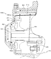
- FIG. 4 is an explanatory diagram showing a state of arrangement in a case 21.
- FIG. 3 is a partial cross-sectional view showing the AA partial cross-section of FIG. 2.
- FIG. 3 is a partial cross-sectional view showing a BB partial cross section of FIG. 2.
- FIG. 1 is a configuration diagram showing an outline of a configuration of a power transmission device 20 as an embodiment of the present invention.
- the power transmission device 20 of the embodiment is configured as a transaxle device that is mounted on the automobile 10 and shifts the power from the engine 12 and transmits the power to the left and right front wheels 18a and 18b.
- a torque converter 22 with a lock-up clutch having an input-side pump impeller 23 connected to the shaft 14 and an output-side turbine runner 24, and a hydraulic oil (lubricant) that is disposed downstream of the torque converter 22 and driven by the engine 12 Oil pump 30 for pumping oil), input shaft 41 connected to turbine runner 24 of torque converter 22, and output shaft 42.
- Oil pump 30 for pumping oil Oil pump 30 for pumping oil
- Hydraulic stepped automatic transmission 40 and hydraulic oil from oil pump 30 The hydraulic circuit 50 is supplied to the torque converter 22 (lock-up clutch) and the automatic transmission 40 (clutch and brake) as needed, and is connected to the output shaft 42 of the automatic transmission 40 and the front wheel 18a. , 18b, a gear mechanism 60 connected to axles 19a, 19b via a differential mechanism (differential gear) 70, and a case 21 (see FIG. 2) for housing them.
- the oil pump 30 is configured as a so-called gear pump having a pump assembly 31 including a pump body 32 and a pump cover 34 fixed to a case 21 (see FIG. 2), and an external gear 35 disposed in the pump assembly 31.
- the external gear 35 is connected to the pump impeller 23 via the hub 25 and forms a crescent with internal teeth (not shown) formed in the pump body 32.
- the pump body 32 is formed with a discharge oil passage 33 (see FIGS. 2 and 4) for discharging the lubricating oil.
- the outer periphery of the hub 25 and the inner periphery of the pump body 32 are sealed by an oil seal 36 to prevent leakage of the lubricating oil (discharge of the lubricating oil from other than the discharge oil passage 33).
- the oil pump 30 configured in this manner sucks the lubricating oil stored in the bottom portion of the case 21 (hereinafter referred to as the storage portion 21 a), and most of the oil is stored.
- the discharge oil passage 33 is formed so that the lubricating oil moves obliquely upward and is discharged, but the lubricating oil is pumped by the rotation of the external gear 35. Therefore, it is possible to discharge the leaking hydraulic oil through the discharge oil passage 33.
- the automatic transmission 40 is configured as a four-stage stepped transmission capable of switching between forward 1st to 4th, reverse, and neutral by changing the engagement state (on / off) of a plurality of clutches and brakes. .
- ON / OFF of the clutch and the brake is performed by adjusting the hydraulic pressure applied to the clutch and the brake by the operation of the hydraulic circuit 50.
- the gear mechanism 60 includes a counter drive gear 61 attached to the output shaft 42 of the automatic transmission 40, a counter driven gear 63 attached to a counter shaft 62 disposed in parallel to the output shaft 42, and meshed with the counter drive gear 61.
- a differential pinion gear (final drive gear) 64 attached to the shaft 62 and a differential ring gear (final driven gear) 65 that meshes with the differential pinion gear 64 and is connected to a differential mechanism (differential gear) 70 are provided.
- the differential mechanism 70 is configured as a well-known differential gear, and is rotatably supported in the case 21 and connected to the differential ring gear 65, and a shaft rotatably supported by the differential case 71.
- Each side gear has an axle 19a connected to the front wheels 18a, 18b, 19b is connected.
- FIG. 2 is an explanatory view showing a state of arrangement in the case 21,
- FIG. 3 is a partial cross-sectional view showing a partial cross-section AA in FIG. 2
- FIG. 4 is a partial cross-section BB in FIG. FIG.
- a solid line arrow indicates the rotation direction of the counter driven gear 63 and the differential ring gear 65 during forward traveling
- a broken line arrow in FIGS. 2 to 4 indicates the flow of the lubricating oil.
- the differential ring gear 65 is a lubricating oil in which a part of the outer teeth is stored in the storage portion 21 a at a position on the lower left side in the figure in the case 21 (hereinafter, this lubricating oil is referred to as stored oil).
- the case 21 is formed so that the bottom 80a is lowered toward the upper left side (upper right side in FIG. 2) of the counter driven gear 63 toward the inner wall surface side (left side in the figure) of the case 21.
- a catch tank 80 capable of temporarily storing lubricating oil is provided, and a counter shaft 62 is rotatably supported along the inner wall surface of the case 21 on the lower left side of the catch tank 80 in the figure.
- a clearance (hereinafter referred to as an oil passage) 82 for guiding the lubricating oil from the catch tank 80 by gravity is formed in the bearing 62a. Therefore, the lubricating oil in the catch tank 80 flows to the left side in FIG.
- the catch tank 80 is assumed to be open to the atmosphere at a different location from the oil passage 82 side. Therefore, when the lubricating oil supplied to the catch tank 80 is large, a part of the lubricating oil overflows from the catch tank 80. Further, a portion (hereinafter referred to as a ceiling portion) 21b located above the differential ring gear 65 in the case 21 is formed so as to be lowered toward the catch tank 80 side (left side in the figure).
- the lubricating oil that has been scraped up by the differential ring gear 65 and the counter driven gear 63 and has reached the ceiling portion 21b moves to the catch tank 80 side through the ceiling portion 21b and drops by gravity, thereby supplying the catch tank 80. Is done.
- the case 21 is formed with an oil passage 84 that communicates a position that aligns with the oil passage 33 for discharging the oil pump 30 and a position that is above the catch tank 80. ing. Accordingly, the leaking hydraulic oil (lubricating oil) discharged through the discharge oil passage 33 is supplied to the catch tank 80 through the oil passage 84. Note that the amount of hydraulic fluid that leaks through the oil passage 84 increases as the rotational speed of the external gear 35 increases (the amount of hydraulic fluid pumped increases).
- the amount of hydraulic oil pumped by the oil pump 30 is reduced, so that the discharged supply oil is reduced, but the lubricating oil stored in the storage portion 21a is increased (the oil level is reduced). Therefore, the amount of lubricating oil (hereinafter referred to as “diff-squeezed-up reaching oil”) that is scraped up by the differential ring gear 65 and reaches the catch tank 80 via the ceiling portion 21b tends to increase. Therefore, even if one of the discharged supply oil and the differential lift-up reaching oil is small, the discharged supply oil, the differential lift-up reaching oil, and the counter driven gear 63 are scraped up and reach the catch tank 80 via the ceiling portion 21b.
- a certain amount of lubricating oil is supplied to the catch tank 80 as the total amount of lubricating oil, and it is possible to suppress a shortage of lubricating oil supplied to the bearing 62a.
- the leaking hydraulic oil (lubricating oil) discharged from the oil pump 30 and guided by the oil passage 84 and the lubricating oil scraped up by the differential ring gear 65 and the counter driven gear 63 are once collected in the catch tank 80 and passed through the oil passage 82. Therefore, the oil passage 82 can be simplified as compared with those in which an oil passage leading to the bearing 62a is formed for each of the bearings 62a.
- the upper part of the catch tank 80 is opened to the atmosphere, when there is a large amount of discharged supply oil or scooping up oil, a part of the lubricating oil overflows from the catch tank 80, and the lubricating oil is excessive in the bearing 62a. It can suppress that it is supplied to. Moreover, since the leakage hydraulic oil (lubricating oil) discharged from the oil pump 30 is once supplied to the catch tank 80 (the upper part is open to the atmosphere) via the oil passage 84, the leakage hydraulic oil is excessively accumulated in the oil passage 84. And a large pressure can be prevented from acting on the oil seal 82 and the oil passage 84.
- the lubricating oil scraped up by the differential ring gear 65 is directly supplied to the bearing 62a.
- the lubricating oil scraped up by the differential ring gear 65 is supplied to the bearing 62a via the ceiling portion 21b, the catch tank 80, and the oil passage 82. can do.
- the catch tank 80 receives the lubricating oil scraped up by the catch tank 80, the oil passage 82 for supplying the lubricating oil of the catch tank 80 to the bearing 62a, and the differential ring gear 65. 80 is provided, and an oil passage 84 that guides leakage hydraulic oil (lubricating oil) discharged from the oil pump 30 to the catch tank 80 is provided, and is scraped up by the differential ring gear 65 and passes through the ceiling 21b.
- the lubricating oil supplied to the bearing 62a can be suppressed.
- the lubricating oil discharged from the oil pump 30 and guided by the oil passage 84 and the lubricating oil scraped up by the differential ring gear 65 are once collected in the catch tank 80 and supplied to the bearing 62a through the oil passage 82.
- the oil passage 84 can be simplified as compared with the case where the oil passage is formed so that both are guided to the bearing 62a.
- the ceiling portion 21b of the case 21 is formed so as to be lowered toward the catch tank 80 side.
- the lubrication scraped up by the differential ring gear 65 is used. It is good also as what forms a catch tank so that oil can be received.
- the width of the bottom portion 180 a of the catch tank 180 may be formed to a width that can receive the lubricating oil scraped up by the differential ring gear 65.
- the leakage hydraulic oil (lubricating oil) discharged from the oil pump 30 and guided by the oil passage 84 and the lubricating oil scooped up by the differential ring gear 65 and the counter driven gear 63 are once in the catch tank 80.
- the lubricant oil is collected by the counter driven gear 63, the lubricant oil collected by the counter driven gear 63 may not be collected in the catch tank 80.
- the catch tank 80 and the oil passage 82 are formed separately, but may be formed integrally.
- the lubricating oil of the catch tank 80 is supplied to the bearing 62a via the oil passage 82.
- the lubricating oil is not limited to the bearing 62a, and other bearings, gears, shafts, etc. It may be supplied to any member (object to be lubricated).
- the automatic transmission 40 having a four-speed transmission capable of switching between forward 1st to 4th speeds, reverse and neutral is provided.
- the power transmission apparatus 20 includes a hydraulic transmission
- a transmission having any number of stages such as a 5-speed, 6-speed, and 8-speed may be provided, or a continuously variable transmission may be provided.
- the automatic transmission 40 corresponds to a “transmission”
- the storage portion 21a of the case 21 corresponds to a “storage portion”
- the oil pump 30 corresponds to a “pressure pump”
- a gear having a differential ring gear 65a
- the mechanism 60 corresponds to a “gear mechanism”
- the ceiling 21 b of the case 21, the catch tank 80, and the oil passage 82 correspond to a “receiving guide portion”
- the oil passage 84 corresponds to a “leaking hydraulic oil guide portion”.
- the present invention can be used in the power transmission device manufacturing industry.
Landscapes
- Engineering & Computer Science (AREA)
- General Engineering & Computer Science (AREA)
- Mechanical Engineering (AREA)
- General Details Of Gearings (AREA)
Abstract
Description
車両に搭載されると共にケースに収容され、原動機からの動力を車軸に伝達する油圧式の変速機を備える動力伝達装置であって、
潤滑油を貯留する貯留部と、
前記原動機によって駆動され、前記貯留部に貯留されている潤滑油を前記変速機の作動油として該変速機に圧送する圧送用ポンプと、
前記貯留部に貯留されている潤滑油を回転に伴って掻き上げる掻き上げギヤと、
前記掻き上げギヤによって掻き上げられる潤滑油を受け止めて所定の潤滑対象に導く受け止めガイド部と、
前記圧送用ポンプから作動油を圧送する際に漏れる漏れ作動油を前記受け止めガイド部に導く漏れ作動油用ガイド部と、
を備えることを要旨とする。
Claims (7)
- 車両に搭載されると共にケースに収容され、原動機からの動力を車軸に伝達する油圧式の変速機を備える動力伝達装置であって、
潤滑油を貯留する貯留部と、
前記原動機によって駆動され、前記貯留部に貯留されている潤滑油を前記変速機の作動油として該変速機に圧送する圧送用ポンプと、
前記貯留部に貯留されている潤滑油を回転に伴って掻き上げる掻き上げギヤと、
前記掻き上げギヤによって掻き上げられる潤滑油を受け止めて所定の潤滑対象に導く受け止めガイド部と、
前記圧送用ポンプから作動油を圧送する際に漏れる漏れ作動油を前記受け止めガイド部に導く漏れ作動油用ガイド部と、
を備える動力伝達装置。 - 請求項1記載の動力伝達装置であって、
前記受け止めガイド部は、前記漏れ作動油を前記所定の潤滑対象に導く箇所とは異なる箇所が大気開放されてなる、
動力伝達装置。 - 請求項1または2記載の動力伝達装置であって、
前記受け止めガイド部は、潤滑油を一時的に貯留する本体と、前記掻き上げギヤによって掻き上げられる潤滑油を前記本体に導入する導入部と、前記本体の潤滑油を前記所定の潤滑対象に導く潤滑用ガイド部と、を有する、
動力伝達装置。 - 請求項3記載の動力伝達装置であって、
前記導入部は、前記本体側に向けて低くなるように形成されてなる、
動力伝達装置。 - 請求項3または4記載の動力伝達装置であって、
前記掻き上げギヤと前記所定の潤滑対象との間には遮蔽物が配置されてなる、
動力伝達装置。 - 請求項5記載の動力伝達装置であって、
前記遮蔽物は、カウンタシャフトに取り付けられ、前記変速機の出力軸に取り付けられたカウンタドライブギヤと噛合するカウンタドリブンギヤであり、
前記掻き上げギヤは、前記カウンタシャフトに取り付けられたデファレンシャルピニオンギヤと噛合すると共に前記車軸に接続された差動機構に連結されたデファレンシャルリングギヤであり、
前記所定の潤滑対象は、前記カウンタシャフトを回転自在に支持するベアリングである、
動力伝達装置。 - 請求項6記載の動力伝達装置であって、
前記本体は、前記カウンタドリブンギヤに対して前記デファレンシャルリングギヤギヤとは反対側に配置されてなり、
前記潤滑用ガイド部は、前記ケースの内壁面に沿って形成されてなる、
動力伝達装置。
Priority Applications (3)
| Application Number | Priority Date | Filing Date | Title |
|---|---|---|---|
| DE112011100148T DE112011100148T5 (de) | 2010-03-31 | 2011-02-25 | Kraftübertragungsvorrichtung |
| BR112012020124-7A BR112012020124A2 (pt) | 2010-03-31 | 2011-02-25 | dispositivo de transmissão de energia |
| CN201180009011.0A CN102753863B (zh) | 2010-03-31 | 2011-02-25 | 动力传递装置 |
Applications Claiming Priority (2)
| Application Number | Priority Date | Filing Date | Title |
|---|---|---|---|
| JP2010082491A JP5333320B2 (ja) | 2010-03-31 | 2010-03-31 | 動力伝達装置 |
| JP2010-082491 | 2010-03-31 |
Publications (1)
| Publication Number | Publication Date |
|---|---|
| WO2011122192A1 true WO2011122192A1 (ja) | 2011-10-06 |
Family
ID=44710296
Family Applications (1)
| Application Number | Title | Priority Date | Filing Date |
|---|---|---|---|
| PCT/JP2011/054360 Ceased WO2011122192A1 (ja) | 2010-03-31 | 2011-02-25 | 動力伝達装置 |
Country Status (6)
| Country | Link |
|---|---|
| US (1) | US8366577B2 (ja) |
| JP (1) | JP5333320B2 (ja) |
| CN (1) | CN102753863B (ja) |
| BR (1) | BR112012020124A2 (ja) |
| DE (1) | DE112011100148T5 (ja) |
| WO (1) | WO2011122192A1 (ja) |
Cited By (2)
| Publication number | Priority date | Publication date | Assignee | Title |
|---|---|---|---|---|
| WO2013047018A1 (ja) * | 2011-09-29 | 2013-04-04 | アイシン・エィ・ダブリュ株式会社 | 動力伝達装置 |
| JP2013194771A (ja) * | 2012-03-16 | 2013-09-30 | Honda Motor Co Ltd | 終減速装置 |
Families Citing this family (23)
| Publication number | Priority date | Publication date | Assignee | Title |
|---|---|---|---|---|
| US20120283060A1 (en) * | 2011-05-02 | 2012-11-08 | American Axle & Manufacturing, Inc. | Lubrication distribution within rear drive module |
| JP2014015979A (ja) * | 2012-07-09 | 2014-01-30 | Honda Motor Co Ltd | ディファレンシャルギヤのベアリング潤滑構造 |
| JP5790630B2 (ja) * | 2012-12-05 | 2015-10-07 | トヨタ自動車株式会社 | 潤滑油供給構造 |
| JP5920235B2 (ja) * | 2013-02-04 | 2016-05-18 | トヨタ自動車株式会社 | 車両用駆動装置 |
| US8960362B2 (en) * | 2013-06-28 | 2015-02-24 | Caterpillar Inc. | Lubrication arrangement for a drive axle of a haul vehicle |
| JP6188616B2 (ja) * | 2014-03-27 | 2017-08-30 | アイシン・エィ・ダブリュ株式会社 | 動力伝達装置 |
| JP6022628B2 (ja) * | 2015-03-30 | 2016-11-09 | 本田技研工業株式会社 | 伝動装置 |
| JP6314947B2 (ja) * | 2015-10-02 | 2018-04-25 | トヨタ自動車株式会社 | 動力伝達装置の冷却構造 |
| US9631715B1 (en) * | 2015-10-20 | 2017-04-25 | Ford Global Technologies, Llc | One-piece integrated chain snubber and oil diverter for a transaxle |
| JP2017118774A (ja) * | 2015-12-25 | 2017-06-29 | 三菱自動車工業株式会社 | 車両駆動用電動機の油冷却システム |
| DE102016212369A1 (de) * | 2016-07-07 | 2018-01-11 | Zf Friedrichshafen Ag | Fahrzeuggetriebe |
| JP6446425B2 (ja) * | 2016-12-20 | 2018-12-26 | 本田技研工業株式会社 | 動力装置 |
| JP2019074104A (ja) * | 2017-10-12 | 2019-05-16 | トヨタ自動車株式会社 | 車両用動力伝達装置 |
| JP6954183B2 (ja) * | 2018-02-28 | 2021-10-27 | トヨタ自動車株式会社 | 車両用駆動装置 |
| JP6927086B2 (ja) * | 2018-03-02 | 2021-08-25 | トヨタ自動車株式会社 | 車両用動力伝達装置の潤滑装置 |
| JP6927087B2 (ja) * | 2018-03-02 | 2021-08-25 | トヨタ自動車株式会社 | 車両用動力伝達装置の潤滑装置 |
| JP6923753B2 (ja) * | 2018-04-26 | 2021-08-25 | 本田技研工業株式会社 | 車両用動力伝達装置 |
| CN110296185B (zh) * | 2019-08-06 | 2024-01-30 | 特百佳动力科技股份有限公司 | 一种重型变速箱 |
| JP7051926B2 (ja) * | 2020-03-25 | 2022-04-11 | 本田技研工業株式会社 | 車両用動力伝達装置の潤滑構造 |
| JP7671157B2 (ja) * | 2021-03-08 | 2025-05-01 | ニデック株式会社 | 駆動装置 |
| JP7501485B2 (ja) * | 2021-09-28 | 2024-06-18 | 株式会社アイシン | 車両用駆動装置 |
| JP7829436B2 (ja) * | 2022-07-27 | 2026-03-13 | ダイハツ工業株式会社 | 変速機 |
| JPWO2024203567A1 (ja) * | 2023-03-31 | 2024-10-03 |
Citations (4)
| Publication number | Priority date | Publication date | Assignee | Title |
|---|---|---|---|---|
| JPS6353068U (ja) * | 1986-09-25 | 1988-04-09 | ||
| JPH0616760U (ja) * | 1992-06-08 | 1994-03-04 | 三菱自動車工業株式会社 | オイルポンプの支持構造 |
| JP2007085409A (ja) * | 2005-09-21 | 2007-04-05 | Jatco Ltd | 自動変速装置 |
| JP2009250422A (ja) * | 2008-04-10 | 2009-10-29 | Toyota Motor Corp | 動力伝達装置の流体通路構造 |
Family Cites Families (6)
| Publication number | Priority date | Publication date | Assignee | Title |
|---|---|---|---|---|
| US4429587A (en) * | 1981-09-10 | 1984-02-07 | General Electric Company | Attitude insensitive lubrication systems |
| DE3209514C2 (de) * | 1982-03-16 | 1984-04-26 | BHS-Bayerische Berg-, Hütten- und Salzwerke AG, 8000 München | In sich geschlossene Getriebeanlage mit Druckschmierung |
| JPS60107450U (ja) * | 1983-12-23 | 1985-07-22 | トヨタ自動車株式会社 | 自動車用終減速機の潤滑機構 |
| JP4500177B2 (ja) * | 2005-02-21 | 2010-07-14 | アイシン・エーアイ株式会社 | 変速機 |
| JP4632204B2 (ja) | 2005-09-21 | 2011-02-16 | アステラス製薬株式会社 | 下痢型過敏性腸症候群治療剤 |
| JP4898653B2 (ja) * | 2007-12-27 | 2012-03-21 | アイシン・エィ・ダブリュ株式会社 | 車両用動力伝達装置 |
-
2010
- 2010-03-31 JP JP2010082491A patent/JP5333320B2/ja not_active Expired - Fee Related
-
2011
- 2011-02-25 DE DE112011100148T patent/DE112011100148T5/de not_active Withdrawn
- 2011-02-25 BR BR112012020124-7A patent/BR112012020124A2/pt not_active Application Discontinuation
- 2011-02-25 WO PCT/JP2011/054360 patent/WO2011122192A1/ja not_active Ceased
- 2011-02-25 CN CN201180009011.0A patent/CN102753863B/zh not_active Expired - Fee Related
- 2011-03-08 US US13/042,896 patent/US8366577B2/en not_active Expired - Fee Related
Patent Citations (4)
| Publication number | Priority date | Publication date | Assignee | Title |
|---|---|---|---|---|
| JPS6353068U (ja) * | 1986-09-25 | 1988-04-09 | ||
| JPH0616760U (ja) * | 1992-06-08 | 1994-03-04 | 三菱自動車工業株式会社 | オイルポンプの支持構造 |
| JP2007085409A (ja) * | 2005-09-21 | 2007-04-05 | Jatco Ltd | 自動変速装置 |
| JP2009250422A (ja) * | 2008-04-10 | 2009-10-29 | Toyota Motor Corp | 動力伝達装置の流体通路構造 |
Cited By (4)
| Publication number | Priority date | Publication date | Assignee | Title |
|---|---|---|---|---|
| WO2013047018A1 (ja) * | 2011-09-29 | 2013-04-04 | アイシン・エィ・ダブリュ株式会社 | 動力伝達装置 |
| JP2013072551A (ja) * | 2011-09-29 | 2013-04-22 | Aisin Aw Co Ltd | 動力伝達装置 |
| US9309959B2 (en) | 2011-09-29 | 2016-04-12 | Aisin Aw Co., Ltd. | Power transmission device |
| JP2013194771A (ja) * | 2012-03-16 | 2013-09-30 | Honda Motor Co Ltd | 終減速装置 |
Also Published As
| Publication number | Publication date |
|---|---|
| US20110245009A1 (en) | 2011-10-06 |
| JP2011214641A (ja) | 2011-10-27 |
| JP5333320B2 (ja) | 2013-11-06 |
| CN102753863A (zh) | 2012-10-24 |
| BR112012020124A2 (pt) | 2020-08-18 |
| US8366577B2 (en) | 2013-02-05 |
| CN102753863B (zh) | 2015-06-10 |
| DE112011100148T5 (de) | 2012-10-04 |
Similar Documents
| Publication | Publication Date | Title |
|---|---|---|
| JP5333320B2 (ja) | 動力伝達装置 | |
| JP5408218B2 (ja) | 動力伝達装置 | |
| US3601515A (en) | Lubricant pump | |
| JP4898653B2 (ja) | 車両用動力伝達装置 | |
| US8821332B2 (en) | Power transmission device | |
| JP4744581B2 (ja) | 車両用動力伝達装置 | |
| JP4898654B2 (ja) | 車両用動力伝達装置 | |
| WO2014155934A1 (ja) | 変速機の潤滑構造 | |
| CN104728408B (zh) | 变速器的润滑结构 | |
| JP2009127794A (ja) | 自動変速機 | |
| JP2009074564A (ja) | オイル供給装置 | |
| CN103775596B (zh) | 用于自动变速器的液压泵结构 | |
| JP2010007761A (ja) | 動力伝達装置の潤滑装置 | |
| JP4814772B2 (ja) | ディファレンシャル装置の潤滑構造 | |
| JP2015090213A (ja) | ポンプスプライン潤滑構造 | |
| KR20250093549A (ko) | 기어 박스 및 자동차 | |
| JP2014240680A (ja) | 変速機の潤滑構造 | |
| JP4986601B2 (ja) | 車両用駆動装置の潤滑構造 | |
| CN108006175A (zh) | 一种摩托车变速箱 | |
| JP5790138B2 (ja) | 潤滑油供給装置 | |
| CN105351505A (zh) | 一种带贯通轴取力器的变速器润滑系统 | |
| JP2006144993A (ja) | リバースアイドラ軸の潤滑構造 | |
| KR102094031B1 (ko) | 수동변속기 윤활구조 | |
| KR20000019175U (ko) | 수동 변속기의 오일 공급 장치 | |
| CN115539605A (zh) | 一种纯电动装载机变速器 |
Legal Events
| Date | Code | Title | Description |
|---|---|---|---|
| WWE | Wipo information: entry into national phase |
Ref document number: 201180009011.0 Country of ref document: CN |
|
| 121 | Ep: the epo has been informed by wipo that ep was designated in this application |
Ref document number: 11762432 Country of ref document: EP Kind code of ref document: A1 |
|
| WWE | Wipo information: entry into national phase |
Ref document number: 1120111001487 Country of ref document: DE Ref document number: 112011100148 Country of ref document: DE |
|
| WWE | Wipo information: entry into national phase |
Ref document number: 7227/CHENP/2012 Country of ref document: IN |
|
| WWE | Wipo information: entry into national phase |
Ref document number: 1201004065 Country of ref document: TH |
|
| 122 | Ep: pct application non-entry in european phase |
Ref document number: 11762432 Country of ref document: EP Kind code of ref document: A1 |
|
| REG | Reference to national code |
Ref country code: BR Ref legal event code: B01A Ref document number: 112012020124 Country of ref document: BR |
|
| ENP | Entry into the national phase |
Ref document number: 112012020124 Country of ref document: BR Kind code of ref document: A2 Effective date: 20120810 |