WO2011121646A1 - カバーフィルム剥離装置及びカバーフィルム剥離方法 - Google Patents
カバーフィルム剥離装置及びカバーフィルム剥離方法 Download PDFInfo
- Publication number
- WO2011121646A1 WO2011121646A1 PCT/JP2010/002314 JP2010002314W WO2011121646A1 WO 2011121646 A1 WO2011121646 A1 WO 2011121646A1 JP 2010002314 W JP2010002314 W JP 2010002314W WO 2011121646 A1 WO2011121646 A1 WO 2011121646A1
- Authority
- WO
- WIPO (PCT)
- Prior art keywords
- adhesive tape
- cover film
- adhesive
- roller
- pressing
- Prior art date
- Legal status (The legal status is an assumption and is not a legal conclusion. Google has not performed a legal analysis and makes no representation as to the accuracy of the status listed.)
- Ceased
Links
Images









Classifications
-
- B—PERFORMING OPERATIONS; TRANSPORTING
- B65—CONVEYING; PACKING; STORING; HANDLING THIN OR FILAMENTARY MATERIAL
- B65H—HANDLING THIN OR FILAMENTARY MATERIAL, e.g. SHEETS, WEBS, CABLES
- B65H41/00—Machines for separating superposed webs
-
- B—PERFORMING OPERATIONS; TRANSPORTING
- B29—WORKING OF PLASTICS; WORKING OF SUBSTANCES IN A PLASTIC STATE IN GENERAL
- B29C—SHAPING OR JOINING OF PLASTICS; SHAPING OF MATERIAL IN A PLASTIC STATE, NOT OTHERWISE PROVIDED FOR; AFTER-TREATMENT OF THE SHAPED PRODUCTS, e.g. REPAIRING
- B29C63/00—Lining or sheathing, i.e. applying preformed layers or sheathings of plastics; Apparatus therefor
- B29C63/0004—Component parts, details or accessories; Auxiliary operations
- B29C63/0013—Removing old coatings
-
- B—PERFORMING OPERATIONS; TRANSPORTING
- B32—LAYERED PRODUCTS
- B32B—LAYERED PRODUCTS, i.e. PRODUCTS BUILT-UP OF STRATA OF FLAT OR NON-FLAT, e.g. CELLULAR OR HONEYCOMB, FORM
- B32B43/00—Operations specially adapted for layered products and not otherwise provided for, e.g. repairing; Apparatus therefor
- B32B43/006—Delaminating
-
- B—PERFORMING OPERATIONS; TRANSPORTING
- B65—CONVEYING; PACKING; STORING; HANDLING THIN OR FILAMENTARY MATERIAL
- B65H—HANDLING THIN OR FILAMENTARY MATERIAL, e.g. SHEETS, WEBS, CABLES
- B65H2801/00—Application field
- B65H2801/61—Display device manufacture, e.g. liquid crystal displays
Definitions
- the present invention is a cover film peeling apparatus for peeling a cover film bonded to protect the surface of a plate material by the adhesive force of an adhesive tape, and is particularly bonded to a polarizing plate used in a liquid crystal display panel.
- the present invention relates to a cover film peeling apparatus and a cover film peeling method suitable for peeling a cover film.
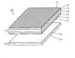
- a cover film is formed on the surfaces of the polarizing plates 112 and 112 used in the liquid crystal display panel 110 in order to prevent damage to the surfaces of the polarizing plates 112 and 112 in the manufacturing process of the liquid crystal display panel 110.
- 111 and 111 are pasted.
- the liquid crystal display module 100 includes a liquid crystal display panel 110 and a backlight unit 120 for illuminating the liquid crystal display panel 110. Before the liquid crystal display panel 110 and the backlight unit 120 are joined, a liquid crystal display is provided. The cover film 111 attached to the polarizing plate 112 of the panel 110 is peeled off.
- a cover film peeling method for peeling the cover film 111 affixed to the polarizing plate 112
- a pressure-sensitive adhesive tape (not shown) is pressed against and adhered to the cover film 111, and the cover film 111 is peeled by moving the pressure-sensitive adhesive tape.
- a method has been proposed. When the cover film 111 is peeled manually, dust scattered from the human body may adhere to the surface of the polarizing plate 112 after the cover film 111 is peeled off, and the function of the liquid crystal display panel 110 may be impaired. The work is becoming mechanized.
- a cover film peeling apparatus for example, in Patent Document 1, as shown in FIG. 7, an adhesive tape is provided at a position where a cover film 203 attached to the surface of the polarizing plate 202 adsorbed to the adsorption plate 201 is disposed. After the guide means 204 is moved horizontally, the cover film 203 is transferred by conveying the adhesive tape 207 spanned from the adhesive tape supply means 205 to the adhesive tape collection means 206 from the adhesive tape supply means 205 to the adhesive tape collection means 206.
- a cover film peeling apparatus 200 for peeling from the polarizing plate 202 is disclosed.
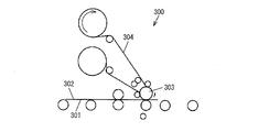
- an adhesive tape 304 is attached to the front end portion of the cover film 302 attached to the surface of the plate material 301 by a pressing roller 303.
- the pressure roller 303 is rotated in the direction of winding the adhesive tape 304, and the cover film 302 is peeled from the plate material 301 while being wound around the pressure roller 303 by the adhesive force of the adhesive tape 304.
- FIG. 8B the front end portion of the cover film 302 wound around the pressing roller 303 is sandwiched by a film clamper 310, and the film clamper 310 is lifted upward, whereby the cover film 302 is removed from the plate material 301. It comes to peel from.
- Japanese Patent Publication Japanese Patent Laid-Open No. 11-174229 (published July 2, 1999)” Japanese Patent Publication “Japanese Patent Laid-Open No. 6-278936 (published Oct. 4, 1994)”
- the wrapping angle of the cover film 302 around the pressing roller 303 is increased, the adhesive area between the adhesive tape 304 and the cover film 302 is increased, so that the adhesive force is increased and the cover film 302 is successfully peeled from the plate material 301.
- the rate can be increased, there is a problem that the consumption of the adhesive tape 304 increases.
- the present invention has been made in view of the above-described conventional problems, and its purpose is to reliably peel the cover film bonded to the plate material from the plate material with the adhesive tape and to reduce the consumption of the adhesive tape. It is providing the cover film peeling apparatus and cover film peeling method which are obtained.
- the cover film peeling apparatus of the present invention presses an adhesive tape against a cover film bonded to a plate material, and peels the cover film from the plate material by the adhesive force of the adhesive tape.
- an adhesive tape supply roller for supplying the adhesive tape
- an adhesive tape recovery roller for recovering the adhesive tape
- a rotation driving means for rotating the adhesive tape supply roller and the adhesive tape recovery roller in forward and reverse directions, respectively.
- an adhesive tape pressing member that presses a part of the adhesive surface of the adhesive tape spanned between the adhesive tape supply roller and the adhesive tape recovery roller against a cover film bonded to a plate material, and the adhesive tape The pressing member is not used on the adhesive tape at the tip of the cover film.
- the pressure-sensitive adhesive surface is pressed and adhered, and the rotation driving means is configured such that the unused adhesive surface of the adhesive tape adheres to the tip of the cover film, and then the cover film is used on the adhesive surface after use of the adhesive tape.
- the adhesive tape supply roller is rotated so as to convey the adhesive tape in the direction opposite to the supply direction in order to adhere the portion other than the tip of the adhesive.
- the cover film peeling method of the present invention presses an adhesive tape against a cover film bonded to a plate material, and peels the cover film from the plate material by the adhesive force of the adhesive tape.
- the unused adhesive surface of the adhesive tape spanned between the adhesive tape supply roller and the adhesive tape recovery roller is pressed against the tip of the cover film bonded to the plate material and adhered, and the cover film After the unused adhesive surface of the adhesive tape is adhered to the tip of the adhesive tape, the adhesive tape is opposite to the supply direction in order to adhere parts other than the tip of the cover film with the adhesive surface after use of the adhesive tape. It is characterized by being conveyed in the direction.
- the adhesive surface after use in an adhesive tape is a used adhesive surface that has been peeled off by sticking the cover film at least once, and remains adhesive.
- the cover film peeling device presses the adhesive tape against the cover film bonded to the plate material, and peels the cover film from the plate material by the adhesive force of the adhesive tape.
- the unused adhesive surface of the adhesive tape is pressed and adhered to the tip of the cover film with the adhesive tape pressing member.
- the adhesive tape supply roller is used to convey the adhesive tape in a direction opposite to the supply direction so that the rotation drive means adheres a part other than the tip of the cover film to the adhesive surface after use in the adhesive tape. Rotate.
- the adhesive tape is transported in the direction opposite to the supply direction, and sticks to the used part of the adhesive tape in the cover film that is sequentially peeled off.
- unused adhesive tape does not consume more than the amount to be adhered to the tip of the cover film.
- unused adhesive tape is used in a minimum amount at the front end of the cover film. For this reason, the consumption of an adhesive tape can be reduced.
- the cover film that is sequentially peeled off is not peeled only by the adhesive force of the adhesive tape adhered to the tip of the cover film. Adhere to the part after use. As a result, the adhesive strength remains even in the portion after use, thereby increasing the adhesive strength. For this reason, like patent document 2, peeling of the cover film from a board
- the cover film peeling apparatus includes a pressure-sensitive adhesive tape supply roller that supplies a pressure-sensitive adhesive tape, a pressure-sensitive adhesive tape collection roller that collects the pressure-sensitive adhesive tape, a pressure-sensitive adhesive tape supply roller, and a pressure-sensitive adhesive tape collection roller.
- Rotation drive means for rotating in the reverse and reverse directions, and an adhesive for pressing a part of the adhesive surface of the adhesive tape spanned between the adhesive tape supply roller and the adhesive tape collecting roller against the cover film bonded to the plate material
- a tape pressing member, and the adhesive tape pressing member presses and adheres an unused adhesive surface of the adhesive tape to the tip of the cover film, and the rotation driving means is attached to the tip of the cover film.
- cover with the adhesive surface after use of the adhesive tape In order to adhere the portion other than the tip of Irumu, the feed direction of the adhesive tape which is intended to rotate the adhesive tape supply roller to convey the opposite direction.
- the cover film peeling method of the present invention is a front end portion of a cover film in which an unused adhesive surface in an adhesive tape that is stretched between an adhesive tape supply roller and an adhesive tape recovery roller is bonded to a plate material.
- the adhesive film is adhered to the tip of the cover film after the unused adhesive surface is adhered to the tip of the cover film, and then the adhesive tape is adhered to a portion other than the tip of the cover film on the adhesive surface after use of the adhesive tape. Therefore, this is a method of transporting the adhesive tape in the direction opposite to the supply direction.
- the cover film bonded to the plate material is surely peeled off from the plate material with the adhesive tape, and the cover film peeling apparatus and the cover film peeling method capable of reducing the consumption amount of the adhesive tape are provided.
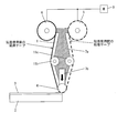
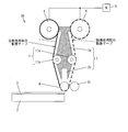
- FIG. 1 shows an embodiment of a cover film peeling apparatus according to the present invention, and is a side view showing a configuration of a cover film peeling apparatus. It is a side view which shows a cover film peeling apparatus when the front-end
- a cover film peeling apparatus it is a side view which shows the adhesive tape of the final state when a cover film is collect
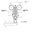
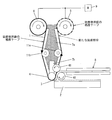
- the other embodiment of the cover film peeling apparatus in this invention is shown, Comprising: It is a side view which shows the structure of a cover film peeling apparatus. It is a side view which shows a cover film peeling apparatus when the front-end
- FIG. 1A is a side view showing the configuration of the cover film peeling apparatus 10.
- the cover film peeling apparatus 10 of this Embodiment is an apparatus which peels the cover film 3 bonded together to the board
- the cover film peeling apparatus 10 includes an adhesive tape pressing roller 4 as an adhesive tape pressing member, a first moving unit and a second moving unit (not shown) that are moving means, an adhesive tape supply roller 5, and an adhesive tape collecting roller. 6 and a rotation drive motor 9 as a rotation drive means for rotating the adhesive tape supply roller 5 and the adhesive tape recovery roller 6 forward and backward, respectively.
- the cover film peeling apparatus 10 includes a base 7 including a first base 7a and a second base 7b, and a tension control member 11 including a first tension control member 11a and a second tension control member 11b, and a cover.
- a cover film collecting unit 8 as film collecting means is further provided.
- the base 7, the tension control member 11, and the cover film collection unit 8 are not necessarily present in the present invention.
- the adhesive tape supply roller 5, the adhesive tape recovery roller 6, the tension control member 11 and the adhesive tape pressing roller 4 are supported by the first base 7a.
- the adhesive tape 1 is pulled out from the adhesive tape supply roller 5, wound around the first tension control member 11a, the adhesive tape pressing roller 4 and the second tension control member 11b, and recovered by the adhesive tape recovery roller 6. At this time, the adhesive tape 1 is wound so that the adhesive surface is on the outside, and the adhesive tape 1 is supplied to the adhesive tape 1 by a rotation drive motor 9 that rotationally drives the adhesive tape supply roller 5 and the adhesive tape recovery roller 6. It can be conveyed in the forward / reverse direction with respect to the direction.
- the first tension control member 11a and the second tension control member 11b apply tension to the adhesive tape 1 so that the adhesive tape 1 wound around the adhesive tape pressing roller 4 does not loosen.
- the pressure-sensitive adhesive tape pressing roller 4 that is a pressure-sensitive adhesive tape pressing member is configured by a rotatable roller shown in FIG.
- the pressure-sensitive adhesive tape pressing member of the present invention is not necessarily limited to this.
- the pressing surface may be formed flat so that the pressing position can be easily aligned, or a combination of this and a roller. May be.
- the first moving part not shown in FIG. 1A is the direction along the surface where the cover film 3 to be peeled is bonded, and the direction in which the cover film 3 is separated, that is, the adhesive tape pressing roller 4 presses the cover film 3.
- the first base 7a is moved in the direction of advancing and retreating.
- an actuator capable of controlling movement by an electrical signal is preferably used.
- the pressure-sensitive adhesive tape pressing roller 4 is supported by the second base 7b, and the second base 7b is moved away from the surface of the plate 2 to which the cover film 3 to be peeled is bonded by the second moving part. You may make it move with respect to the 1st base 7a.
- the second moving unit is preferably configured to be able to control the pressing force applied to the plate member 2 by the adhesive tape pressing roller 4, and for example, a spring, an air cylinder, or the like is preferably used.
- the adhesive tape supply roller 5, the adhesive tape recovery roller 6, the first base 7a and the second base 7b, and the adhesive tape pressing roller 4 are adhesive tape guides that regulate the travel path of the adhesive tape 1 in the present invention. It functions as a means.
- the plate material 2 on which the cover film 3 is bonded is put into the cover film peeling apparatus 10.
- the first base 7 a and the second base 7 b are moved forward by a moving unit (not shown) so that the adhesive tape pressing roller 4 presses the tip of the cover film 3.
- the unused adhesive surface of the adhesive tape 1 wound around the adhesive tape pressing roller 4 is adhered to the tip of the cover film 3.
- tip part of the cover film 3 which adheres the unused adhesive surface in the adhesive tape 1 is 1 mm or more and 1/10 or less of the diagonal length of the cover film 3, for example.
- tip part of the cover film 3 which adheres the unused adhesive surface in the adhesive tape 1 contains the corner
- the adhesive force of the adhesive tape 1 is sufficient to obtain an opportunity for peeling at the tip of the cover film 3, and the adhesive force needs to be greater than the adhesive force between the cover film 3 and the plate material 2. This is because.
- the direction along the surface of the plate material 2 on which the cover film 3 to be peeled is bonded, with the adhesive tape pressing roller 4 pressing the tip of the cover film 3.
- the first base 7a and the second base 7b are further translated by the moving unit.
- the entire cover film 3 is peeled from the plate 2 by further transporting the adhesive tape 1 in the direction opposite to the adhesive tape supply direction by the adhesive tape supply roller 5 and the adhesive tape recovery roller 6. At this time, the entire cover film 3 is adhered to the unused adhesive surface of the adhesive tape 1 and the adhesive surface after use.
- the adhesive tape 1 is conveyed in the adhesive tape supply direction, that is, in the clockwise direction by the adhesive tape supply roller 5 and the adhesive tape recovery roller 6, and adheres to the adhesive tape pressing roller 4.
- the cover film 3 is peeled off from the adhesive tape 1 and collected by the cover film collecting unit 8 arranged on the tape collecting roller 6 side.
- the cover film collecting unit 8 is composed of an upper plate 8a and a lower plate 8b having a gap 8c into which the cover film 3 can be inserted, and the adhesive film 1 is conveyed by conveying the adhesive tape 1 in the supply direction or in the opposite direction.
- the cover film 3 adhered to the tape 1 can be inserted into the gap 8c between the upper plate 8a and the lower plate 8b. That is, in the cover film collecting unit 8, for example, the upper plate 8a protrudes more toward the adhesive tape pressing roller 4 side than the lower plate 8b, and the adhesive tape is in the center at the tip of the upper plate 8a on the adhesive tape pressing roller 4 side. A recess 8d wider than 1 is formed.
- the cover film collection unit 8 by moving the cover film collection unit 8 in the direction of the adhesive tape pressing roller 4 and in the direction parallel to the plate member 2, the width of the adhesive tape 1 is reduced as shown in FIG. Since it is narrower than the width of the cover film 3, the cover film 3 can slide to the back side of the upper plate 8 a and the cover film 3 can be collected in the gap 8 c of the cover film collection unit 8.
- the cover film recovery unit 8 may be disposed on the adhesive tape supply roller 5 side with respect to the adhesive tape pressing roller 4. In this case, the adhesive tape 1 is removed by the adhesive tape supply roller 5 and the adhesive tape recovery roller 6. The cover film 3 is peeled off and collected from the adhesive tape 1 when being sent in the direction opposite to the adhesive tape supply direction, that is, in the counterclockwise direction.
- the non-adhesive part before use of the adhesive tape 1 adheres to the pressing part of the adhesive tape pressing roller 4, that is, the part where the adhesive tape pressing roller 4 presses the cover film 3.
- the adhesive tape 1 is moved in the adhesive tape supply direction (clockwise direction) or in the direction opposite to the adhesive tape supply direction (counterclockwise direction) so that the tape 1 is positioned. Transport.
- the non-adhesion part before using the adhesive tape 1 conveys the adhesive tape 1 so that only the front-end
- the adhesive tape 1 is pressed against the cover film 3 bonded to the plate 2, and the cover film 3 is removed by the adhesive force of the adhesive tape 1. Peel from the plate 2.
- the cover film peeling device 10 rotates the adhesive tape supply roller 5 for supplying the adhesive tape 1, the adhesive tape recovery roller 6 for recovering the adhesive tape 1, the adhesive tape supply roller 5, and the adhesive tape recovery roller 6. And a rotation drive motor 9 that rotates in the reverse direction, and a cover film 3 in which a part of the adhesive surface of the adhesive tape 1 spanned between the adhesive tape supply roller 5 and the adhesive tape recovery roller 6 is bonded to the plate 2. And an adhesive tape pressing roller 4 to be pressed.
- the pressure-sensitive adhesive tape pressing roller 4 presses and adheres an unused pressure-sensitive adhesive surface of the pressure-sensitive adhesive tape 1 to the tip of the cover film 3, and the rotational drive motor 9 After the adhesive surface in use is adhered, the adhesive tape 1 is transported in the direction opposite to the supply direction so as to adhere the portion other than the tip of the cover film 3 with the adhesive surface after use in the adhesive tape 1.
- the adhesive tape supply roller 5 is rotated.
- the cover film peeling apparatus 10 presses the adhesive tape 1 against the cover film 3 bonded to the plate material 2 and peels the cover film 3 from the plate material 2 by the adhesive force of the adhesive tape 1.
- the adhesive tape pressing roller 4 is used to press and adhere the unused adhesive surface of the adhesive tape 1 to the tip of the cover film 3.
- the adhesive tape 1 is transported in the direction opposite to the supply direction so as to adhere the portion other than the tip of the cover film 3 on the adhesive surface after use in the adhesive tape 1 by the rotary drive motor 9.
- the adhesive tape supply roller 5 is rotated.
- the adhesive tape 1 is conveyed in the reverse direction to a supply direction, and adheres to the part after the use of the adhesive tape 1 in the cover film 3 peeled one by one. .
- the unused adhesive tape 1 does not consume more than the amount to be adhered to the tip of the cover film 3. That is, the unused adhesive tape 1 is used in a necessary minimum amount at the front end portion of the cover film 3. For this reason, the consumption of the adhesive tape 1 can be reduced.
- a cover film peeling apparatus 10 and a cover film peeling method capable of reliably peeling the cover film 3 bonded to the plate material 2 from the plate material 2 with the pressure-sensitive adhesive tape 1 and reducing the consumption amount of the pressure-sensitive adhesive tape 1. Can do.
- the unused portion of the adhesive tape 1 reaches a predetermined position by moving the adhesive tape 1 in the adhesive tape supply direction. Then, the adhesive tape 1 is conveyed. Thereby, peeling of the cover film 3 in the next board
- the adhesive tape guide means which regulates the travel path of the adhesive tape 1 is provided so that relative movement with respect to the cover film 3 is possible
- the adhesive tape guide means is The first base 7a that rotatably supports the adhesive tape supply roller 5 and the adhesive tape collection roller 6 and the adhesive tape pressing roller 4 are fixed, and the adhesive tape pressing roller 4 is in the direction of pressing the cover film 3. It is possible to provide a second base 7b supported by the first base 7a so as to be movable forward and backward.
- the adhesive tape supply roller 5, the adhesive tape collection roller 6, and the adhesive tape pressing roller 4 can be integrally moved relative to the cover film 3 by the adhesive tape guide means, The position of the tip portion and the position of the adhesive tape 1 can be easily aligned. As a result, the cover film 3 can be reliably peeled off with the minimum necessary amount of the adhesive tape 1. Further, the cover film 3 can be easily peeled off from the plate 2 by moving the adhesive tape guiding means and the plate 2 relative to the surface of the plate 2, for example.
- the cover film peeling apparatus 10 of this Embodiment is provided with the cover film collection
- recovery part 8 is the clearance gap 8c into which the cover film 3 can be inserted.
- the upper plate 8a and the lower plate 8b are provided, and the adhesive tape 1 is transported in the supply direction or in the opposite direction so that the cover film 3 adhered to the adhesive tape 1 is attached to the upper plate 8a and the lower plate. 8b can be inserted into the gap 8c.
- recovery part 8 consists of the upper side board 8a and the lower side board 8b which have the clearance gap 8c which can insert the cover film 3, and supplies the adhesive tape 1 to a supply direction or the opposite direction.
- the cover film 3 adhered to the adhesive tape 1 can be inserted into the gap 8c between the upper plate 8a and the lower plate 8b.
- the adhesive tape 1 after use is generally less adhesive than when not in use. Therefore, since the cover film 3 adhered to the adhesive surface after use in the adhesive tape 1 is easily peeled off from the adhesive tape 1, it can be easily recovered by the cover film recovery unit 8.
- the cover film 3 when the cover film 3 is continuously peeled from the plate material 2, the previously peeled cover film 3 has been peeled off from the adhesive tape 1, so that the previously peeled cover film 3 does not interfere with the next.
- the cover film 3 can be peeled off.
- the cover film 3 can be peeled repeatedly and under the same conditions, and the cover film 3 can be peeled repeatedly and reliably.
- FIGS. 2 (a) to 2 (c) The configurations other than those described in the present embodiment are the same as those in the first embodiment.
- members having the same functions as those shown in the drawings of the first embodiment are given the same reference numerals, and explanation thereof is omitted.
- one adhesive tape pressing roller 4 as an adhesive tape pressing member is provided in the cover film peeling apparatus 10 of the first embodiment.
- the cover film peeling apparatus 20 in the present embodiment is shown in FIG.
- the first adhesive tape pressing roller 4a and the second adhesive tape pressing roller 4b as the adhesive tape pressing members are different in that a plurality of such as two are installed.
- the structure other than that is the same structure as the cover film peeling apparatus 10 of the said Embodiment 1.
- the cover film peeling apparatus 20 in this Embodiment while installing the 1st adhesive tape press roller 4a in the peeling start side of the cover film 3, ie, the front side of the cover film 3,
- the second adhesive tape pressing roller 4b is installed so as to be adjacent to the center side with respect to the first adhesive tape pressing roller 4a with respect to the front end portion of the cover film 3.
- the first adhesive tape pressing roller 4a can move in the direction in which the cover film 3 is peeled, that is, in the retreat direction with respect to the pressing direction. ing.
- the plate material 2 on which the cover film 3 is bonded is put into the cover film peeling apparatus 20.
- the unused part of the adhesive tape 1 wound between the first adhesive tape pressing roller 4 a and the second adhesive tape pressing roller 4 b is the tip of the cover film 3.
- the base 7 composed of the first base 7a and the second bases 7b and 7b is moved forward by a moving part (not shown) so as to press the part, and wound around the first adhesive tape pressing roller 4a and the second adhesive tape pressing roller 4b.
- the unused adhesive surface of the applied adhesive tape 1 is adhered to the tip of the cover film 3.
- the first adhesive tape pressing roller 4 a moves backward in the direction of peeling the cover film 3, thereby obtaining a trigger for peeling the cover film 3.
- the subsequent operations are the same as those described with reference to FIGS. 1 (d) to 1 (f).
- a plurality of adhesive tape pressing rollers such as the first adhesive tape pressing roller 4a and the second adhesive tape pressing roller 4b, are provided.
- the first adhesive tape pressing roller 4a is installed on the peeling start side of the cover film 3, and the second adhesive tape pressing roller 4b is placed from the tip of the cover film 3 with respect to the first adhesive tape pressing roller 4a. Is also installed adjacent to the center side.
- an intermediate position between the first adhesive tape pressing roller 4 a and the second adhesive tape pressing roller 4 b in the adhesive tape 1 can be positioned and pressed at the end of the cover film 3.
- the posture of the pressure-sensitive adhesive tape 1 wound between the first pressure-sensitive adhesive tape pressing roller 4a and the second pressure-sensitive adhesive tape pressing roller 4b is the surface of the plate 2 on which the cover film 3 to be peeled is bonded. It can be made substantially parallel and substantially flat.
- the cover film 3 can be peeled off by retreating the first adhesive tape pressing roller 4a located in front of the cover film 3 from the state where the adhesive tape 1 is pressed in parallel with the cover film 3. .
- tip part of the cover film 3 can be peeled by the retreat movement of the 1st adhesive tape press roller 4a, without conveying the adhesive tape 1 by the adhesive tape supply roller 5 and the adhesive tape collection
- the first adhesive tape pressing roller 4a does not need to be present on the cover film 3, and the unused adhesive tape 1 wound between the first adhesive tape pressing roller 4a and the second adhesive tape pressing roller 4b is unused.
- the part should just be located in the front-end
- the first adhesive tape pressing roller 4a and the second adhesive tape pressing roller 4b are made of a material harder than the plate material 2, the extreme end portion of the plate material 2 that is likely to be cracked or chipped is formed on the first adhesive tape pressing roller 4a. Or since it does not press with the 2nd adhesive tape press roller 4b, it can suppress that the board
- FIGS. 3 (a) to 3 (d) The configurations other than those described in the present embodiment are the same as those in the first embodiment and the second embodiment.
- members having the same functions as those shown in the drawings of Embodiment 1 and Embodiment 1 are given the same reference numerals, and the description thereof is omitted.
- the cover film peeling device 30 in the present embodiment is provided with a pressing member 31 on the side of the adhesive tape pressing roller 4, and the adhesive tape pressing roller 4 and the pressing member 31
- the point that the adhesive tape 1 and the peeled cover film 3 are sandwiched therebetween is different from the cover film peeling apparatus 10 of the first embodiment.
- the structure of those other than this is the same as that of the cover film peeling apparatus 10 of the said Embodiment 1.
- the pressing member 31 is disposed on the adhesive tape supply roller 5 side with respect to the adhesive tape pressing roller 4.
- the gap with the adhesive tape pressing roller 4 can be moved freely.
- the plate material 2 on which the cover film 3 is bonded is put into the cover film peeling apparatus 30.
- the base 7 including the first base 7 a and the second base 7 b is moved by a moving unit (not shown) so that the adhesive tape pressing roller 4 presses the tip of the cover film 3.
- the adhesive tape pressing roller 4 presses the tip of the cover film 3.
- the base 7 is translated by the moving unit in the direction along the surface.
- the adhesive tape 1 is transported in the direction opposite to the adhesive tape supply direction by the adhesive tape supply roller 5 and the adhesive tape collection roller 6 to obtain an opportunity for peeling the cover film 3.
- the pressing member 31 is in a position that maintains a gap larger than the thickness of the adhesive tape 1 and the cover film 3 between the pressing tape 4 and the pressing member 31 after the cover film 3 is conveyed to the clamping position. 31 moves in parallel to the adhesive tape pressing roller 4 side, and sandwiches the adhesive tape 1 and the peeled cover film 3.
- the base 7 is moved obliquely by the moving part in the direction along the surface of the plate 2 where the cover film 3 to be peeled is bonded and in the direction away from the surface.
- the base 7 is further moved and the adhesive tape 1 is conveyed in the direction opposite to the adhesive tape supply direction by the adhesive tape supply roller 5 and the adhesive tape recovery roller 6.
- the entire cover film 3 is peeled from the plate material 2.
- the entire cover film 3 is adhered to the unused adhesive surface and the used adhesive surface of the adhesive tape 1.
- this adhesive tape 1 is a direction opposite to a supply direction.
- a pressing member 31 is provided to press the adhered cover film 3 against the adhesive tape when transported to the adhesive tape. That is, in the present embodiment, the adhesive tape 1 and the peeled cover film 3 are sandwiched between the adhesive tape pressing roller 4 and the pressing member 31.
- the peeled cover film can be sandwiched between the pressure-sensitive adhesive tape 1 and the pressing member 31. Since the cover film 3 is supported by the clamping force between the adhesive tape 1 and the pressing member 31, the cover film 3 can be peeled off more reliably.
- the conveyance of the adhesive tape 1 by the adhesive tape supply roller 5 and the adhesive tape recovery roller 6 is stopped, and the base 7 is moved obliquely by the moving unit.
- the angle between the surface of the cover film 3 to be peeled and the peeled cover film 3 can be freely adjusted to an angle suitable for peeling the cover film 3, so that the entire cover film 3 is peeled off. Can be performed more reliably.
- the configurations other than those described in the present embodiment are the same as those in the first to third embodiments.
- members having the same functions as those shown in the drawings of Embodiments 1 to 3 are given the same reference numerals, and descriptions thereof are omitted.
- the cover film peeling apparatus 40 in the present embodiment is implemented in that a cover film collection guide portion 41 is arranged on the adhesive tape supply roller 5 side with respect to the adhesive tape pressing roller 4. This is a point different from the cover film peeling apparatus 10 of the first embodiment.
- the cover film collection guide portion 41 is disposed at a position where it does not interfere with the adhesive tape 1 and at a position where movement of the peeled cover film 3 is restricted.
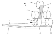
- 4 (a) and 4 (b) are side views of the cover film peeling apparatus 40
- FIGS. 5 (a) and 5 (b) are partial perspective views thereof.
- the plate material 2 to which the cover film 3 is bonded is put into the cover film peeling device 40, and the adhesive tape pressing roller 4 presses the front end of the cover film 3.
- the base 7 composed of the first base 7 a and the second base 7 b is moved forward by a moving part (not shown), and the unused adhesive surface of the adhesive tape 1 wound around the adhesive tape pressing roller 4 is used as the tip of the cover film 3. Adhere to.
- the base 7 is moved in parallel in the direction along the surface of the plate 2 on which the cover film 3 to be peeled is bonded, and the adhesive tape 1 is moved by the adhesive tape supply roller 5 and the adhesive tape recovery roller 6. Is transported in the direction opposite to the adhesive tape supply direction to obtain an opportunity for peeling the cover film 3.
- the width of the pressure-sensitive adhesive tape pressing roller 4 is smaller than the width of the cover film 3 and larger than the width of the pressure-sensitive adhesive tape 1.
- the cover film collection guide portion 41 is disposed at an outer position that does not interfere with the adhesive tape 1.
- the peeled cover film 3 is peeled from the adhesive tape 1 and sent to the cover film collection part 8 as cover film collection means.
- the cover film collection guide unit 41 is arranged so as to sandwich the peeled cover film 3 and is a pinch roller that is driven to rotate, so that the peeled cover film 3 is more reliably attached to the cover film collection unit 8. Can send.
- the subsequent operation is the same as that described with reference to FIG.
- the cover film 3 can insert the cover film 3
- the cover film 3 is composed of an upper plate 8a and a lower plate 8b having a gap, and the adhesive tape 1 is conveyed in the direction opposite to the supply direction, whereby the cover film 3 adhered to the adhesive tape 1 is removed from the cover film collection guide section. 41, it can be inserted into the gap 8c between the upper plate 8a and the lower plate 8b.
- the cover film 3 released from the plate material 2 is peeled off from the adhesive tape 1 and recovered by the cover film recovery guide unit 41 and the cover film recovery unit 8, so that the separation process of the cover film 3 and the adhesive tape 1 is performed. It can be performed.
- recovery part 8 consists of the upper side board 8a and the lower side board 8b which have the clearance gap 8c which can insert the cover film 3, and is the direction opposite to the supply direction of the adhesive tape 1
- the cover film 3 adhered to the adhesive tape 1 can be inserted into the gap 8c between the upper plate 8a and the lower plate 8b.
- the adhesive tape 1 after use is generally less adhesive than when not in use. Therefore, since the cover film 3 adhered to the adhesive surface after use in the adhesive tape 1 is easily peeled off from the adhesive tape 1, it can be easily recovered by the cover film recovery unit 8.
- the cover film 3 when the cover film 3 is continuously peeled from the plate material 2, the previously peeled cover film 3 has been peeled off from the adhesive tape 1, so that the previously peeled cover film 3 does not interfere with the next.
- the cover film 3 can be peeled off.
- the cover film 3 can be peeled repeatedly and under the same conditions, and the cover film 3 can be peeled repeatedly and reliably.
- the adhesive tape guide means for regulating the travel path of the adhesive tape is provided so as to be relatively movable with respect to the cover film
- the adhesive tape guide means is The adhesive tape supply roller and the adhesive tape recovery roller, a first base that rotatably supports the adhesive tape supply roller and the adhesive tape recovery roller, the adhesive tape pressing member fixed, and the adhesive tape pressing member It is preferable to include a second base supported by the first base so as to be able to move forward and backward with respect to the pressing direction to the cover film.
- the adhesive tape supply roller, the adhesive tape recovery roller, and the adhesive tape pressing member can be integrally moved relative to the cover film by the adhesive tape guide means, the position of the front end portion of the cover film and The position of the adhesive tape can be easily aligned.
- the cover film can be reliably peeled off with the minimum amount of adhesive tape.
- the cover film can be easily peeled from the plate material by moving the adhesive tape guiding means and the plate material, for example, relative to the surface of the plate material.
- the present invention provides specific means for moving the adhesive tape pressing member forward and backward in the pressing direction toward the surface of the plate material on which the cover film to be peeled is bonded, and in this specific means, the adhesive tape pressing It becomes possible to make it the structure which can control pressing force by the advancing / retreating movement of the member to the pressing direction. As a result, it becomes easy to control the pressing force of the adhesive tape against the plate material. Therefore, since the pressing force of the adhesive tape against the plate material can be minimized, for example, even if the plate material is a thin glass substrate, the cover film can be peeled without being damaged.
- a spring, an air cylinder, etc. can be used suitably, for example.
- the cover film peeling apparatus of the present invention it is preferable that a plurality of the adhesive tape pressing members are provided.
- the first adhesive tape pressing member and the second adhesive tape pressing member in the adhesive tape
- the intermediate position can be positioned at the end of the cover film and pressed.
- the cover film can be peeled off by retreating, for example, the first adhesive tape pressing member located in front of the cover film from the state where the adhesive tape is pressed in parallel with the cover film.
- tip part of a cover film can be peeled by the retraction movement of a 1st adhesive tape press member, without conveying the adhesive tape by an adhesive tape supply roller and an adhesive tape collection
- the first adhesive tape pressing member and the second adhesive tape pressing member are harder than the plate material
- the first adhesive tape pressing member or the second adhesive tape pressing member is the endmost portion of the plate material that is likely to be cracked or chipped. Since it does not press with a member, it can suppress that a board
- the adhesive film peeling apparatus of the present invention after the unused adhesive surface of the adhesive tape was adhered to the tip of the cover film, the adhesive film was adhered when transported in the direction opposite to the supply direction. It is preferable that a pressing member that presses the cover film against the adhesive tape side is provided.
- the peeled-off cover film can be sandwiched between the pressure-sensitive adhesive tape and the pressing member, and the pressure-sensitive adhesive strength of the pressure-sensitive adhesive tape and the pressure-sensitive adhesive tape Since the cover film is supported by the clamping force with the pressing member, the cover film can be peeled more reliably.
- the cover film peeling apparatus of the present invention includes cover film collecting means for collecting the peeled cover film, and the cover film collecting means includes an upper plate and a lower plate having a gap into which the cover film can be inserted. It is preferable that the cover film adhered to the adhesive tape can be inserted into the gap between the upper plate and the lower plate by conveying the adhesive tape in the supply direction or in the opposite direction. .
- the cover film collecting means is composed of an upper plate and a lower plate having a gap into which the cover film can be inserted, and the adhesive film is conveyed in the supply direction or in the opposite direction, thereby providing the adhesive film.
- the cover film adhered to the tape can be inserted into the gap between the upper plate and the lower plate.
- the adhesive tape after use is generally less adhesive than when not in use. Therefore, since the cover film adhered to the adhesive surface after use in the adhesive tape is easily peeled off from the adhesive tape, it can be easily recovered by the cover film recovery means.
- the cover film when the cover film is continuously peeled from the plate material, the first peeled cover film is peeled off from the adhesive tape, so that the next peeled film is peeled off without interference. It can be performed. As a result, the cover film can be repeatedly peeled under the same conditions, and the cover film can be peeled repeatedly and reliably.
- the cover film can be reliably peeled off and the consumption of the adhesive tape can be reduced as compared with the conventional method.
- the cover film of the polarizing plate in the manufacturing process of the liquid crystal display panel is peeled off. It can utilize suitably for the cover film peeling apparatus and cover film peeling method to perform.
Landscapes
- Engineering & Computer Science (AREA)
- Manufacturing & Machinery (AREA)
- Folding Of Thin Sheet-Like Materials, Special Discharging Devices, And Others (AREA)
Abstract
本発明のカバーフィルム剥離装置(10)は、粘着テープ供給ローラ(5)と、粘着テープ回収ローラ(6)と、粘着テープ供給ローラ(5)及び粘着テープ回収ローラ(6)をそれぞれ正回転及び逆回転に回転させる回転駆動モータ(9)と、粘着テープ供給ローラ(5)と粘着テープ回収ローラ(6)との間に架け渡された粘着テープ(1)における一部の粘着面を板材(2)に貼り合わされたカバーフィルム(3)に押圧させる粘着テープ押圧ローラ(4)とを備える。粘着テープ押圧ローラ(4)は、カバーフィルム(3)の先端部に粘着テープ(1)における未使用の粘着面を押圧して粘着させる共に、回転駆動モータ(9)は、カバーフィルム(3)の先端部に粘着テープ(1)における未使用の粘着面が粘着した後、該粘着テープ(1)における使用後の粘着面にてカバーフィルム(3)の先端部以外の部分を粘着すべく、該粘着テープ(1)を供給方向とは逆方向へ搬送するように粘着テープ供給ローラ(5)を回転させる。これにより、板材に貼り合わされたカバーフィルムを粘着テープにて板材から確実に剥離すると共に、粘着テープの消費量を低減し得るカバーフィルム剥離装置及びカバーフィルム剥離方法を提供する。
Description
本発明は、板材の表面を保護するために貼り合わされたカバーフィルムを、粘着テープの粘着力によって剥離するカバーフィルム剥離装置であって、特に、液晶表示パネルに用いられている偏光板に貼り合わされたカバーフィルムを剥離するのに適したカバーフィルム剥離装置及びカバーフィルム剥離方法に関するものである。
図6に示すように、液晶表示パネル110に用いられている偏光板112・112の表面には、液晶表示パネル110の製造工程における該偏光板112・112の表面の損傷を防ぐために、カバーフィルム111・111が貼り付けられている。
液晶表示モジュール100は、液晶表示パネル110と液晶表示パネル110を照明するためのバックライトユニット120とによって構成されており、これら液晶表示パネル110とバックライトユニット120とを接合する前に、液晶表示パネル110の偏光板112に貼り付けられたカバーフィルム111は剥離される。
上記偏光板112に貼り付けられたカバーフィルム111を剥離するカバーフィルム剥離方法として、図示しない粘着テープをカバーフィルム111に押圧して粘着させ、この粘着テープを移動させることによってカバーフィルム111を剥離する方法が提案されている。カバーフィルム111の剥離作業を人手によって行う場合、人体から飛散した塵埃がカバーフィルム111剥離後の偏光板112表面に付着し、液晶表示パネル110の機能を損ねる恐れがあるため、カバーフィルム111の剥離作業を機械化するようになってきている。
このようなカバーフィルム剥離装置として、例えば特許文献1には、図7に示すように、吸着プレート201に吸着された偏光板202の表面に貼り付けられたカバーフィルム203の配設位置に粘着テープ案内手段204を水平移動した後、粘着テープ供給手段205から粘着テープ回収手段206まで架け渡された粘着テープ207を粘着テープ供給手段205から粘着テープ回収手段206まで搬送することによって、カバーフィルム203を偏光板202から剥離するカバーフィルム剥離装置200が開示されている。
また、例えば特許文献2に開示されたカバーフィルム剥離装置300では、図8(a)に示すように、板材301の表面に貼り付けられたカバーフィルム302の先端部に押圧ローラ303により粘着テープ304を押圧し、粘着テープ304を巻き取る方向に押圧ローラ303を回転させ、カバーフィルム302を粘着テープ304の粘着力により押圧ローラ303に巻き付けつつ板材301から剥離させる。次いで、図8(b)に示すように、押圧ローラ303に巻き付いたカバーフィルム302の先端部をフィルムクランパ310にて挟持し、このフィルムクランパ310を上方へ引き上げることにより、カバーフィルム302を板材301から剥離するようになっている。
しかしながら、上記従来の特許文献1に開示されたカバーフィルム剥離装置200では、カバーフィルム203の長さ方向全域に粘着テープ207を貼り付けているので、粘着テープ207の消費量が多いという問題がある。
また、特許文献2に開示されたカバーフィルム剥離装置300では、押圧ローラ303により粘着テープ304をカバーフィルム302の先端部に押圧して粘着させた後、フィルムクランパ310にて挟持する前に、押圧ローラ303をカバーフィルム302側の表面から離間する方向に少し移動させることによって、カバーフィルム302を板材301から剥離する。
このため、押圧ローラ303の外周のみの粘着テープ304による粘着力がカバーフィルム302を板材301から剥離するのに必要な力に対して充分でない場合には、カバーフィルム302が粘着テープ304から剥がれてしまうので、板材301からのカバーフィルム302の剥離が失敗することになる。
一方、カバーフィルム302の押圧ローラ303への巻き付け角度を大きくすれば、粘着テープ304とカバーフィルム302との粘着面積が増大するので粘着力が増大し、かつ板材301からのカバーフィルム302の剥離成功率を高めることができるが、粘着テープ304の消費量が増えるという問題がある。
本発明は、上記従来の問題点に鑑みなされたものであって、その目的は、板材に貼り合わされたカバーフィルムを粘着テープにて板材から確実に剥離すると共に、粘着テープの消費量を低減し得るカバーフィルム剥離装置及びカバーフィルム剥離方法を提供することにある。
本発明のカバーフィルム剥離装置は、上記課題を解決するために、板材に貼り合わされたカバーフィルムに粘着テープを押圧し、上記粘着テープの粘着力によって上記カバーフィルムを上記板材から剥離するカバーフィルム剥離装置において、上記粘着テープを供給する粘着テープ供給ローラと、上記粘着テープを回収する粘着テープ回収ローラと、上記粘着テープ供給ローラ及び粘着テープ回収ローラをそれぞれ正回転及び逆回転に回転させる回転駆動手段と、上記粘着テープ供給ローラと粘着テープ回収ローラとの間に架け渡された粘着テープにおける一部の粘着面を板材に貼り合わされたカバーフィルムに押圧させる粘着テープ押圧部材とを備え、上記粘着テープ押圧部材は、上記カバーフィルムの先端部に粘着テープにおける未使用の粘着面を押圧して粘着させる共に、上記回転駆動手段は、上記カバーフィルムの先端部に粘着テープにおける未使用の粘着面が粘着した後、該粘着テープにおける使用後の粘着面にてカバーフィルムの先端部以外の部分を粘着すべく、該粘着テープを供給方向とは逆方向へ搬送するように上記粘着テープ供給ローラを回転させることを特徴としている。
本発明のカバーフィルム剥離方法は、上記課題を解決するために、板材に貼り合わされたカバーフィルムに粘着テープを押圧し、上記粘着テープの粘着力によって上記カバーフィルムを上記板材から剥離するカバーフィルム剥離方法において、粘着テープ供給ローラと粘着テープ回収ローラとの間に架け渡された粘着テープにおける未使用の粘着面を板材に貼り合わされたカバーフィルムの先端部に押圧して粘着させる共に、上記カバーフィルムの先端部に粘着テープにおける未使用の粘着面が粘着した後、該粘着テープにおける使用後の粘着面にてカバーフィルムの先端部以外の部分を粘着すべく、該粘着テープを供給方向とは逆方向へ搬送することを特徴としている。
尚、粘着テープにおける使用後の粘着面とは、少なくとも一度カバーフィルムを粘着して剥がしたことがある使用済の粘着面であって、粘着力が残っているものをいう。
上記の発明によれば、カバーフィルム剥離装置は、板材に貼り合わされたカバーフィルムに粘着テープを押圧し、上記粘着テープの粘着力によって上記カバーフィルムを板材から剥離する。
この場合、カバーフィルムを剥離するには、カバーフィルムの先端部において剥離のきっかけが得られればよく、そのために必要な粘着テープの量は少量でよい。
そこで、本発明では、粘着テープ押圧部材にて、カバーフィルムの先端部に粘着テープにおける未使用の粘着面を押圧して粘着させる。次いで、回転駆動手段にて、粘着テープにおける使用後の粘着面にてカバーフィルムの先端部以外の部分を粘着すべく、該粘着テープを供給方向とは逆方向へ搬送するように粘着テープ供給ローラを回転させる。
これにより、カバーフィルムを板材から剥離するときには、粘着テープは、供給方向とは逆方向に搬送され、順次剥離されるカバーフィルムにおける粘着テープの使用後の部分に粘着していく。
この結果、未使用の粘着テープはカバーフィルムの先端部に粘着させる量よりも多く消費しない。すなわち、未使用の粘着テープはカバーフィルムの先端部において必要最小限の量だけ使用される。このため、粘着テープの消費量を低減することができる。
また、本発明では、カバーフィルムを板材から剥離するときに、単に、カバーフィルムの先端部に粘着された粘着テープの粘着力のみで剥離するのではなく、順次剥離されるカバーフィルムが粘着テープの使用後の部分に順次粘着していく。この結果、使用後の部分といえども粘着力は残っているので、これにより粘着力が増大される。このため、特許文献2のように、カバーフィルムが粘着テープから剥がれてしまうことによって板材からのカバーフィルムの剥離が失敗するということもない。
したがって、板材に貼り合わされたカバーフィルムを粘着テープにて板材から確実に剥離すると共に、粘着テープの消費量を低減し得るカバーフィルム剥離装置及びカバーフィルム剥離方法を提供することができる。
本発明のカバーフィルム剥離装置は、以上のように、粘着テープを供給する粘着テープ供給ローラと、上記粘着テープを回収する粘着テープ回収ローラと、上記粘着テープ供給ローラ及び粘着テープ回収ローラをそれぞれ正回転及び逆回転に回転させる回転駆動手段と、上記粘着テープ供給ローラと粘着テープ回収ローラとの間に架け渡された粘着テープにおける一部の粘着面を板材に貼り合わされたカバーフィルムに押圧させる粘着テープ押圧部材とを備え、上記粘着テープ押圧部材は、上記カバーフィルムの先端部に粘着テープにおける未使用の粘着面を押圧して粘着させる共に、上記回転駆動手段は、上記カバーフィルムの先端部に粘着テープにおける未使用の粘着面が粘着した後、該粘着テープにおける使用後の粘着面にてカバーフィルムの先端部以外の部分を粘着すべく、該粘着テープを供給方向とは逆方向へ搬送するように上記粘着テープ供給ローラを回転させるものである。
本発明のカバーフィルム剥離方法は、以上のように、粘着テープ供給ローラと粘着テープ回収ローラとの間に架け渡された粘着テープにおける未使用の粘着面を板材に貼り合わされたカバーフィルムの先端部に押圧して粘着させる共に、上記カバーフィルムの先端部に粘着テープにおける未使用の粘着面が粘着した後、該粘着テープにおける使用後の粘着面にてカバーフィルムの先端部以外の部分を粘着すべく、該粘着テープを供給方向とは逆方向へ搬送する方法である。
それゆえ、板材に貼り合わされたカバーフィルムを粘着テープにて板材から確実に剥離すると共に、粘着テープの消費量を低減し得るカバーフィルム剥離装置及びカバーフィルム剥離方法を提供するという効果を奏する。
〔実施の形態1〕
本発明の一実施形態について図1(a)~図1(f)に基づいて説明すれば、以下のとおりである。図1(a)は、上記カバーフィルム剥離装置10の構成を示す側面図である。
本発明の一実施形態について図1(a)~図1(f)に基づいて説明すれば、以下のとおりである。図1(a)は、上記カバーフィルム剥離装置10の構成を示す側面図である。
本実施の形態のカバーフィルム剥離装置10は、図1(a)に示すように、粘着テープ1の粘着力により、板材2に貼り合わされたカバーフィルム3を板材2から剥がす装置である。そして、カバーフィルム剥離装置10は、粘着テープ押圧部材としての粘着テープ押圧ローラ4と、移動手段である図示しない第1移動部及び第2移動部と、粘着テープ供給ローラ5と、粘着テープ回収ローラ6と、上記粘着テープ供給ローラ5及び粘着テープ回収ローラ6をそれぞれ正回転及び逆回転に回転させる回転駆動手段としての回転駆動モータ9と備えている。
また、カバーフィルム剥離装置10は、第1ベース7a及び第2ベース7bからなるベース7、並びに第1テンション制御部材11a及び第2テンション制御部材11bからなるテンション制御部材11を備えていると共に、カバーフィルム回収手段としてのカバーフィルム回収部8をさらに備えている。尚、本発明においては、これらベース7、テンション制御部材11及びカバーフィルム回収部8は、本発明においては必ずしも存在しなくてもよい。
上記粘着テープ供給ローラ5、粘着テープ回収ローラ6、テンション制御部材11及び粘着テープ押圧ローラ4は、第1ベース7aによって支持されている。
また、粘着テープ1は、粘着テープ供給ローラ5から引き出され、第1テンション制御部材11a、粘着テープ押圧ローラ4及び第2テンション制御部材11bに巻きかけられ、粘着テープ回収ローラ6に回収される。このとき、粘着テープ1は、粘着面が外側になるように巻きかけられており、粘着テープ供給ローラ5及び粘着テープ回収ローラ6を回転駆動する回転駆動モータ9によって、粘着テープ1を粘着テープ供給方向に対して正逆自在に搬送することができる。
上記第1テンション制御部材11a及び第2テンション制御部材11bは、粘着テープ押圧ローラ4に巻き掛けられた粘着テープ1が弛まないように、粘着テープ1にテンションを与える。
尚、本実施の形態では、粘着テープ押圧部材である粘着テープ押圧ローラ4は、粘着テープ1の搬送を滑らかにするように図1(a)に示す回転自在なローラで構成されているが、本発明の粘着テープ押圧部材は、必ずしもこれに限らず、例えば、押圧位置合わせが容易となるように押圧面が平坦に形成されていてもよく、又はこれとローラとの組合せにて構成されていてもよい。
図1(a)に示されていない前記第1移動部は、剥離すべきカバーフィルム3が貼り合わされた面に沿った方向、及び離接する方向つまり粘着テープ押圧ローラ4がカバーフィルム3への押圧に際して進退移動する方向に、第1ベース7aを移動させるものである。第1移動部としては、電気的な信号によって移動を制御できるアクチュエータが好適に用いられる。尚、粘着テープ押圧ローラ4を第2ベース7bにて支持し、第2移動部によって板材2における、剥離すべきカバーフィルム3が貼り合わされた面に対して離接する方向に、第2ベース7bを第1ベース7aに対して移動させるようにしてもよい。第2移動部は、粘着テープ押圧ローラ4による板材2への押圧力を制御可能に構成することが好ましく、例えば、バネやエアシリンダ等が好適に用いられる。
尚、このことから、粘着テープ供給ローラ5、粘着テープ回収ローラ6、第1ベース7a及び第2ベース7b、粘着テープ押圧ローラ4は、本発明における粘着テープ1の走行経路を規制する粘着テープ案内手段として機能している。
次に、上記構成のカバーフィルム剥離装置10における、カバーフィルム3の剥離動作について、図1(a)~図1(f)を参照して以下に説明する。
まず、図1(a)に示すように、カバーフィルム3が貼り合わされた板材2が、カバーフィルム剥離装置10に投入される。
次に、図1(b)に示すように、粘着テープ押圧ローラ4がカバーフィルム3の先端部を押圧するように、図示しない移動部によって第1ベース7a及び第2ベース7bを進出移動させることにより、粘着テープ押圧ローラ4に巻きかけられた粘着テープ1における未使用の粘着面をカバーフィルム3の先端部に粘着させる。尚、粘着テープ1における未使用の粘着面を粘着させるカバーフィルム3の先端部の長さは、例えば1mm以上かつカバーフィルム3の対角長さの10分の1以下が好ましい。また、粘着テープ1における未使用の粘着面を粘着させるカバーフィルム3の先端部はカバーフィルム3の角部を含み、粘着テープ押圧ローラ4はカバーフィルム3の対角線上を走行することが好ましい。この理由は、カバーフィルム3の先端部において剥離のきっかけが得られるだけの粘着テープ1の粘着力が必要であり、その粘着力はカバーフィルム3と板材2との粘着力よりも大きいことが必要であるためである。
次に、図1(c)に示すように、粘着テープ押圧ローラ4がカバーフィルム3の先端部を押圧した状態で、板材2における、剥離すべきカバーフィルム3が貼り合わされた面に沿った方向に移動部によって第1ベース7a及び第2ベース7bを平行移動させる。そして、粘着テープ供給ローラ5及び粘着テープ回収ローラ6によって粘着テープ1を粘着テープ供給方向とは逆方向に搬送することにより、カバーフィルム3の剥離のきっかけを得る。
次に、図1(d)に示すように、粘着テープ押圧ローラ4がカバーフィルム3の先端部を押圧した状態で、板材2における、剥離すべきカバーフィルム3が貼り合わされた面に沿った方向に移動部によって第1ベース7a及び第2ベース7bをさらに平行移動させる。そして、粘着テープ供給ローラ5及び粘着テープ回収ローラ6によって粘着テープ1を粘着テープ供給方向とは逆方向にさらに搬送することにより、カバーフィルム3全体を板材2から剥離する。このとき、カバーフィルム3全体が粘着テープ1の未使用の粘着面及び使用後の粘着面に粘着された状態となる。
次に、図1(e)に示すように、粘着テープ供給ローラ5及び粘着テープ回収ローラ6によって粘着テープ1を粘着テープ供給方向つまり時計回り方向に搬送し、粘着テープ押圧ローラ4に対して粘着テープ回収ローラ6側に配置されたカバーフィルム回収部8にて、カバーフィルム3を粘着テープ1から剥離して回収する。
上記カバーフィルム回収部8は、カバーフィルム3が挿入可能な隙間8cを有する上側板8aと下側板8bとからなっており、かつ粘着テープ1を供給方向又はその反対方向に搬送することにより、粘着テープ1に粘着されたカバーフィルム3を上側板8aと下側板8bとの隙間8cに挿入可能となっている。すなわち、カバーフィルム回収部8は、例えば、上側板8aが下側板8bよりも粘着テープ押圧ローラ4側に突出しており、かつ上側板8aにおける粘着テープ押圧ローラ4側の先端部における中央に粘着テープ1よりも幅の広い凹部8dが形成されている。
この構成により、カバーフィルム回収部8を粘着テープ押圧ローラ4の方向であって板材2と平行な方向に移動させることによって、後述する図5(a)に示すように、粘着テープ1の幅がカバーフィルム3の幅よりも狭いので、カバーフィルム3が上側板8aの裏側に摺動して、カバーフィルム3をカバーフィルム回収部8の隙間8cに回収することができる。
尚、カバーフィルム回収部8は、粘着テープ押圧ローラ4に対して粘着テープ供給ローラ5側に配置してもよく、この場合は、粘着テープ供給ローラ5及び粘着テープ回収ローラ6によって粘着テープ1を粘着テープ供給方向とは逆方向つまり反時計回り方向に送る際に、カバーフィルム3を粘着テープ1から剥離して回収する。
次に、図1(f)に示すように、粘着テープ1の使用前である未粘着部が粘着テープ押圧ローラ4の押圧部、つまり粘着テープ押圧ローラ4がカバーフィルム3を押圧する部分に粘着テープ1が位置するように、粘着テープ供給ローラ5及び粘着テープ回収ローラ6によって、粘着テープ供給方向(時計回り方向)又は粘着テープ供給方向とは逆方向(反時計回り方向)に粘着テープ1を搬送する。
このように、本実施の形態では、粘着テープ1の使用前である未粘着部が、カバーフィルム3の先端部のみを押圧するように粘着テープ1を搬送するので、粘着テープ1の消費量を少なくすることができる。また、粘着テープ1の使用前である未粘着部がカバーフィルム3の先端部を押圧して粘着するので、剥離のきっかけを得るための十分な粘着力を有するため、カバーフィルム3の剥離を確実に行うことができる。
以上のように、本実施の形態のカバーフィルム剥離装置10及びカバーフィルム剥離方法は、板材2に貼り合わされたカバーフィルム3に粘着テープ1を押圧し、粘着テープ1の粘着力によってカバーフィルム3を板材2から剥離する。そして、カバーフィルム剥離装置10は、粘着テープ1を供給する粘着テープ供給ローラ5と、粘着テープ1を回収する粘着テープ回収ローラ6と、粘着テープ供給ローラ5及び粘着テープ回収ローラ6をそれぞれ正回転及び逆回転に回転させる回転駆動モータ9と、粘着テープ供給ローラ5と粘着テープ回収ローラ6との間に架け渡された粘着テープ1における一部の粘着面を板材2に貼り合わされたカバーフィルム3に押圧させる粘着テープ押圧ローラ4とを備えている。上記粘着テープ押圧ローラ4は、カバーフィルム3の先端部に粘着テープ1における未使用の粘着面を押圧して粘着させる共に、回転駆動モータ9は、カバーフィルム3の先端部に粘着テープ1における未使用の粘着面が粘着した後、該粘着テープ1における使用後の粘着面にてカバーフィルム3の先端部以外の部分を粘着すべく、該粘着テープ1を供給方向とは逆方向へ搬送するように粘着テープ供給ローラ5を回転させる。
上記の構成によれば、カバーフィルム剥離装置10は、板材2に貼り合わされたカバーフィルム3に粘着テープ1を押圧し、粘着テープ1の粘着力によってカバーフィルム3を板材2から剥離する。
この場合、カバーフィルム3を剥離するには、カバーフィルム3の先端部において剥離のきっかけが得られればよく、そのために必要な粘着テープ1の量は少量でよい。
そこで、本実施の形態では、粘着テープ押圧ローラ4にて、カバーフィルム3の先端部に粘着テープ1における未使用の粘着面を押圧して粘着させる。次いで、回転駆動モータ9にて、粘着テープ1における使用後の粘着面にてカバーフィルム3の先端部以外の部分を粘着すべく、該粘着テープ1を供給方向とは逆方向へ搬送するように粘着テープ供給ローラ5を回転させる。
これにより、カバーフィルム3を板材2から剥離するときには、粘着テープ1は、供給方向とは逆方向に搬送され、順次剥離されるカバーフィルム3における粘着テープ1の使用後の部分に粘着していく。
この結果、未使用の粘着テープ1はカバーフィルム3の先端部に粘着させる量よりも多く消費しない。すなわち、未使用の粘着テープ1はカバーフィルム3の先端部において必要最小限の量だけ使用される。このため、粘着テープ1の消費量を低減することができる。
また、本実施の形態では、カバーフィルム3を板材2から剥離するときに、単に、カバーフィルム3の先端部に粘着された粘着テープ1の粘着力のみで剥離するのではなく、順次剥離されるカバーフィルム3が粘着テープ1の使用後の部分に順次粘着していく。この結果、使用後の部分といえども粘着力は残っているので、これにより粘着力が増大される。このため、前記特許文献2のように、カバーフィルム3が粘着テープ1から剥がれてしまうことによって板材2からのカバーフィルム3の剥離が失敗するということもない。
したがって、板材2に貼り合わされたカバーフィルム3を粘着テープ1にて板材2から確実に剥離すると共に、粘着テープ1の消費量を低減し得るカバーフィルム剥離装置10及びカバーフィルム剥離方法を提供することができる。
尚、本実施の形態では、1個目の板材2におけるカバーフィルム3の剥離が終了すると、粘着テープ1を粘着テープ供給方向へ移動させることによって、粘着テープ1の未使用部分が所定位置まで到達するように粘着テープ1を搬送する。これにより、次の板材2におけるカバーフィルム3の剥離を、1個目の板材2におけるカバーフィルム3と同様に行うことができる。
また、本実施の形態のカバーフィルム剥離装置10では、粘着テープ1の走行経路を規制する粘着テープ案内手段が、カバーフィルム3に対して相対移動可能に設けられていると共に、粘着テープ案内手段は、粘着テープ供給ローラ5及び粘着テープ回収ローラ6を回転可能に支持する第1ベース7aと、粘着テープ押圧ローラ4を固定し、かつ該粘着テープ押圧ローラ4がカバーフィルム3への押圧方向に対して進退移動可能となるように第1ベース7aに支持される第2ベース7bとを備えているとすることができる。
これにより、粘着テープ供給ローラ5及び粘着テープ回収ローラ6並びに粘着テープ押圧ローラ4が、粘着テープ案内手段にて一体となってカバーフィルム3に対して相対移動することができるので、カバーフィルム3の先端部の位置と粘着テープ1の位置とを容易に位置合わせすることができる。この結果、必要最小量の粘着テープ1にてカバーフィルム3の剥離を確実に行うことができる。また、粘着テープ案内手段と板材2とを例えば該板材2の表面に平行に相対的に移動させることによって、カバーフィルム3を板材2から容易に剥離することができる。
さらに、本実施の形態では、板材2における、剥離すべきカバーフィルム3が貼り合わされた面に向けて粘着テープ押圧ローラ4を押圧方向に進退移動させる具体的手段を提供すると共に、この具体的手段では、粘着テープ押圧ローラ4の押圧方向への進退移動によって押圧力を制御し得る構成とすることが可能となる。この結果、板材2に対する粘着テープ1の押圧力を制御することが容易になる。したがって、板材2に対する粘着テープ1の押圧力を最小にすることができるので、例えば板材2が薄いガラス基板であっても損傷することなくカバーフィルム3の剥離を行うことができる。尚、押圧力の制御を可能にする構成として、例えば、バネやエアシリンダ等を好適に用いることができる。
また、本実施の形態のカバーフィルム剥離装置10では、剥離されたカバーフィルム3を回収するカバーフィルム回収部8を備えていると共に、カバーフィルム回収部8は、カバーフィルム3が挿入可能な隙間8cを有する上側板8aと下側板8bとからなっており、かつ粘着テープ1を供給方向又はその反対方向に搬送することにより、該粘着テープ1に粘着されたカバーフィルム3を上側板8aと下側板8bとの隙間8cに挿入可能となっている。
これにより、カバーフィルム回収部8にて、板材2から剥離されたカバーフィルム3を粘着テープ1から引き剥がして回収するので、カバーフィルム3と粘着テープ1との分離処理を行うことができる。
また、本実施の形態では、カバーフィルム回収部8は、カバーフィルム3が挿入可能な隙間8cを有する上側板8aと下側板8bとからなっており、かつ粘着テープ1を供給方向又はその反対方向に搬送することにより、該粘着テープ1に粘着されたカバーフィルム3を上側板8aと下側板8bとの隙間8cに挿入可能となっている。
ここで、使用後の粘着テープ1は、一般的に、未使用時よりも粘着力が低下する。したがって、粘着テープ1における使用後の粘着面に粘着したカバーフィルム3は粘着テープ1から剥離し易いので、カバーフィルム回収部8によって容易に回収することができる。
さらに、板材2からのカバーフィルム3の剥離を連続的に行う場合、先に剥離したカバーフィルム3は粘着テープ1から引き剥がされているので、先に剥離したカバーフィルム3が干渉することなく次のカバーフィルム3の剥離を行うことができる。この結果、繰り返し、同様の条件にてカバーフィルム3の剥離を行うことができ、カバーフィルム3の剥離を繰り返し確実に行うことができる。
〔実施の形態2〕
本発明の他の実施の形態について図2(a)~図2(c)に基づいて説明すれば、以下のとおりである。尚、本実施の形態において説明すること以外の構成は、前記実施の形態1と同じである。また、説明の便宜上、前記の実施の形態1の図面に示した部材と同一の機能を有する部材については、同一の符号を付し、その説明を省略する。
本発明の他の実施の形態について図2(a)~図2(c)に基づいて説明すれば、以下のとおりである。尚、本実施の形態において説明すること以外の構成は、前記実施の形態1と同じである。また、説明の便宜上、前記の実施の形態1の図面に示した部材と同一の機能を有する部材については、同一の符号を付し、その説明を省略する。
前記実施の形態1のカバーフィルム剥離装置10では粘着テープ押圧部材としての粘着テープ押圧ローラ4は1個設けられていたが、本実施の形態におけるカバーフィルム剥離装置20は、図2(a)に示すように、粘着テープ押圧部材としての第1粘着テープ押圧ローラ4a及び第2粘着テープ押圧ローラ4bが、2個等の複数設置されている点が異なっている。尚、それ以外の構成は、前記実施の形態1のカバーフィルム剥離装置10と同様の構成である。
本実施の形態におけるカバーフィルム剥離装置20では、図2(a)に示すように、第1粘着テープ押圧ローラ4aをカバーフィルム3の剥離開始側につまりカバーフィルム3の前方側に設置すると共に、第2粘着テープ押圧ローラ4bを第1粘着テープ押圧ローラ4aに対してカバーフィルム3の先端部よりも中央側に隣接するように設置する。そして、第2粘着テープ押圧ローラ4bがカバーフィルム3を押圧した状態にて、第1粘着テープ押圧ローラ4aがカバーフィルム3を剥離する方向つまり押圧方向に対する退却方向に移動することができるようになっている。
上記構成のカバーフィルム剥離装置20における、カバーフィルム3の剥離動作について、図2(a)~図2(c)を参照して以下に説明する。
まず、図2(a)に示すように、カバーフィルム3が貼り合わされた板材2が、カバーフィルム剥離装置20に投入される。
次に、図2(b)に示すように、第1粘着テープ押圧ローラ4aと第2粘着テープ押圧ローラ4bとの間に巻きかけられた粘着テープ1の未使用部分が、カバーフィルム3の先端部を押圧するように、図示しない移動部によって第1ベース7a及び第2ベース7b・7bからなるベース7を進出移動させて、第1粘着テープ押圧ローラ4a及び第2粘着テープ押圧ローラ4bに巻きかけられた粘着テープ1の未使用の粘着面をカバーフィルム3の先端部に粘着させる。
次に、図2(c)に示すように、第1粘着テープ押圧ローラ4aがカバーフィルム3を剥離する方向に退却移動することにより、カバーフィルム3の剥離のきっかけを得る。以降の動作は、前記図1(d)~図1(f)を参照して説明したものと同様である。
以上のように、本実施の形態のカバーフィルム剥離装置2では、粘着テープ押圧ローラは、第1粘着テープ押圧ローラ4aと第2粘着テープ押圧ローラ4bとの2個等の複数設けられている。具体的には、第1粘着テープ押圧ローラ4aをカバーフィルム3の剥離開始側に設置すると共に、第2粘着テープ押圧ローラ4bを第1粘着テープ押圧ローラ4aに対してカバーフィルム3の先端部よりも中央側に隣接するように設置している。
これにより、例えば、粘着テープ1における第1粘着テープ押圧ローラ4aと第2粘着テープ押圧ローラ4bとの中間位置をカバーフィルム3の端部に位置させて押圧することができる。詳細には、第1粘着テープ押圧ローラ4aと第2粘着テープ押圧ローラ4bとの間に巻きかけられた粘着テープ1の姿勢を、板材2における、剥離すべきカバーフィルム3が貼り合わされた面と略平行かつ略平坦にすることができる。
この結果、粘着テープ1の未使用部分をカバーフィルム3の先端部に位置合わせして容易に粘着させることができる。そして、粘着テープ1がカバーフィルム3と平行に押圧している状態から、カバーフィルム3の前方に位置する第1粘着テープ押圧ローラ4aを退却移動することによって、カバーフィルム3を引き剥がすことができる。このため、粘着テープ供給ローラ5及び粘着テープ回収ローラ6による粘着テープ1の搬送を行わずに、第1粘着テープ押圧ローラ4aの退却移動によってカバーフィルム3の先端部を剥離することができる。
そのため、第1粘着テープ押圧ローラ4aがカバーフィルム3上に存在する必要がなく、第1粘着テープ押圧ローラ4aと第2粘着テープ押圧ローラ4bとの間に巻きかけられた粘着テープ1の未使用部分が、カバーフィルム3の先端部に位置すればよい。この結果、第1粘着テープ押圧ローラ4a及び第2粘着テープ押圧ローラ4bが板材2よりも硬い材質であっても、割れや欠けが生じ易い板材2の最端部を第1粘着テープ押圧ローラ4a又は第2粘着テープ押圧ローラ4bにて押圧しないので、カバーフィルム3の剥離時に板材2を損傷することを抑制することができる。
〔実施の形態3〕
本発明のさらに他の実施の形態について図3(a)~図3(d)に基づいて説明すれば、以下のとおりである。尚、本実施の形態において説明すること以外の構成は、前記実施の形態1及び実施の形態2と同じである。また、説明の便宜上、前記の実施の形態1及び実施の形態1の図面に示した部材と同一の機能を有する部材については、同一の符号を付し、その説明を省略する。
本発明のさらに他の実施の形態について図3(a)~図3(d)に基づいて説明すれば、以下のとおりである。尚、本実施の形態において説明すること以外の構成は、前記実施の形態1及び実施の形態2と同じである。また、説明の便宜上、前記の実施の形態1及び実施の形態1の図面に示した部材と同一の機能を有する部材については、同一の符号を付し、その説明を省略する。
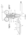
本実施の形態におけるカバーフィルム剥離装置30は、図3(a)に示すように、粘着テープ押圧ローラ4の横側に押さえ部材31を配設し、粘着テープ押圧ローラ4と押さえ部材31との間に粘着テープ1及び剥離されたカバーフィルム3を挟み込むようにしている点が、実施の形態1のカバーフィルム剥離装置10と異なっている点である。尚、これ以外の構成は、前記実施の形態1のカバーフィルム剥離装置10と同様である。
具体的には、本実施の形態のカバーフィルム剥離装置30では、図3(a)に示すように、押さえ部材31は、粘着テープ押圧ローラ4に対して粘着テープ供給ローラ5側に配置されており、粘着テープ押圧ローラ4との間隙を開閉自在に移動することができるようになっている。
上記構成のカバーフィルム剥離装置30によるカバーフィルム3の剥離動作について、図3(a)~図3(d)を参照して以下に説明する。
まず、図3(a)に示すように、カバーフィルム3が貼り合わされた板材2が、カバーフィルム剥離装置30に投入される。
次に、図3(b)に示すように、粘着テープ押圧ローラ4がカバーフィルム3の先端部を押圧するように、図示しない移動部によって第1ベース7a及び第2ベース7bからなるベース7を進出移動させて、粘着テープ押圧ローラ4に巻きかけられた粘着テープ1の未使用の粘着面をカバーフィルム3の先端部に粘着させた後、板材2における、剥離すべきカバーフィルム3が貼り合わされた面に沿った方向に、移動部によってベース7を平行移動させる。次いで、粘着テープ供給ローラ5及び粘着テープ回収ローラ6にて粘着テープ1を粘着テープ供給方向とは逆方向に搬送することによりカバーフィルム3の剥離のきっかけを得る。このとき、押さえ部材31は、粘着テープ押圧ローラ4との間に粘着テープ1及びカバーフィルム3の厚み以上の間隙を保った位置にあり、カバーフィルム3が挟持位置に搬送された後に、押さえ部材31が粘着テープ押圧ローラ4側に平行移動して、粘着テープ1及び剥離されたカバーフィルム3を挟み込む。
次に、図3(c)に示すように、板材2における、剥離すべきカバーフィルム3が貼り合わされた面に沿った方向かつ離間する方向に、移動部によって斜めにベース7を移動させる。
次に、図3(d)に示すように、さらにベース7を移動させると共に、粘着テープ供給ローラ5及び粘着テープ回収ローラ6にて粘着テープ1を粘着テープ供給方向とは逆方向に搬送することにより、カバーフィルム3全体を板材2から剥離する。このとき、カバーフィルム3全体が粘着テープ1の未使用の粘着面及び使用済の粘着面に粘着された状態となる。以降の動作は図1(f)を参照して説明したものと同様である。
以上のように、本実施の形態のカバーフィルム剥離装置30では、カバーフィルム3の先端部に粘着テープ1における未使用の粘着面を粘着させた後、該粘着テープ1を供給方向とは逆方向へ搬送するときに、粘着されたカバーフィルム3を粘着テープ側に押し付ける押さえ部材31が設けられている。すなわち、本実施の形態では、粘着テープ押圧ローラ4と押さえ部材31との間に粘着テープ1及び剥離されたカバーフィルム3を挟み込む構成にしている。
これにより、粘着テープ押圧ローラ4にてカバーフィルム3の剥離のきっかけを得た後、粘着テープ1と押さえ部材31との間に剥離されたカバーフィルムを挟み込むことができ、粘着テープ1の粘着力、及び粘着テープ1と押さえ部材31とによる挟持力によってカバーフィルム3を支持するので、カバーフィルム3の剥離をより確実に行うことができる。
また、粘着テープ1及び剥離されたカバーフィルム3を挟み込んだ状態で、粘着テープ供給ローラ5及び粘着テープ回収ローラ6による粘着テープ1の搬送を停止し、移動部によって斜めにベース7を移動させる。この結果、剥離すべきカバーフィルム3が貼り合わされた面と剥離されたカバーフィルム3とのなす角度を、カバーフィルム3を剥離するのに適する角度に自在に調整できるので、カバーフィルム3全体の剥離をより確実に行うことができる。
〔実施の形態4〕
本発明のさらに他の実施の形態について、図4(a)、図4(b)、図5(a)及び図5(b)に基づいて説明すれば、以下のとおりである。尚、本実施の形態において説明すること以外の構成は、前記実施の形態1~実施の形態3と同じである。また、説明の便宜上、前記の実施の形態1~実施の形態3の図面に示した部材と同一の機能を有する部材については、同一の符号を付し、その説明を省略する。
本発明のさらに他の実施の形態について、図4(a)、図4(b)、図5(a)及び図5(b)に基づいて説明すれば、以下のとおりである。尚、本実施の形態において説明すること以外の構成は、前記実施の形態1~実施の形態3と同じである。また、説明の便宜上、前記の実施の形態1~実施の形態3の図面に示した部材と同一の機能を有する部材については、同一の符号を付し、その説明を省略する。
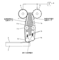
本実施の形態におけるカバーフィルム剥離装置40は、図4(a)に示すように、粘着テープ押圧ローラ4に対して粘着テープ供給ローラ5側にカバーフィルム回収案内部41を配置した点が、実施の形態1のカバーフィルム剥離装置10と異なっている点である。上記カバーフィルム回収案内部41は、粘着テープ1と干渉しない位置、かつ、剥離されたカバーフィルム3の移動を規制する位置に配置される。
上記構成のカバーフィルム剥離装置40におけるカバーフィルム3の剥離動作について、図4(a)、図4(b)、図5(a)及び図5(b)を参照して以下に説明する。図4(a)及び図4(b)はカバーフィルム剥離装置40の側面図であり、図5(a)及び図5(b)はその部分的な斜視図である。
まず、図4(a)に示すように、カバーフィルム3が貼り合わされた板材2が、カバーフィルム剥離装置40に投入され、粘着テープ押圧ローラ4がカバーフィルム3の先端部を押圧するように、図示しない移動部によって第1ベース7a及び第2ベース7bからなるベース7を進出移動させて、粘着テープ押圧ローラ4に巻きかけられた粘着テープ1における未使用の粘着面をカバーフィルム3の先端部に粘着させる。
その後、板材2における、剥離すべきカバーフィルム3が貼り合わされた面に沿った方向に、移動部によってベース7を平行移動させると共に、粘着テープ供給ローラ5及び粘着テープ回収ローラ6にて粘着テープ1を粘着テープ供給方向とは逆方向に搬送することにより、カバーフィルム3の剥離のきっかけを得る。このとき、図5(a)に示すように、粘着テープ押圧ローラ4の幅はカバーフィルム3の幅よりも小さく、かつ粘着テープ1の幅よりも大きい。また、カバーフィルム回収案内部41は粘着テープ1とは干渉しない外側の位置に配置されている。
次に、図4(b)及び図5(b)に示すように、さらにカバーフィルム3の剥離を進行させると、剥離されたカバーフィルム3の粘着テープ1に粘着されていない部分が、カバーフィルム回収案内部41によって規制されるので、剥離されたカバーフィルム3は粘着テープ1から剥離され、カバーフィルム回収手段としてのカバーフィルム回収部8に送られる。ここで、カバーフィルム回収案内部41は、剥離されたカバーフィルム3を挟み込むように配置して原動回転するピンチローラとすることによって、剥離されたカバーフィルム3をより確実にカバーフィルム回収部8に送ることができる。以降の動作は、図1(f)を参照して説明したものと同様である。
このように、本実施の形態のカバーフィルム剥離装置40では、剥離されたカバーフィルム3を回収するカバーフィルム回収部8を備えていると共に、カバーフィルム回収部8は、カバーフィルム3が挿入可能な隙間を有する上側板8aと下側板8bとからなっており、かつ粘着テープ1を供給方向とは反対方向に搬送することにより、該粘着テープ1に粘着されたカバーフィルム3をカバーフィルム回収案内部41にて上側板8aと下側板8bとの隙間8cに挿入可能となっている。
これにより、カバーフィルム回収案内部41及びカバーフィルム回収部8にて、板材2から剥離されたカバーフィルム3を粘着テープ1から引き剥がして回収するので、カバーフィルム3と粘着テープ1との分離処理を行うことができる。
また、本実施の形態では、カバーフィルム回収部8は、カバーフィルム3が挿入可能な隙間8cを有する上側板8aと下側板8bとからなっており、かつ粘着テープ1を供給方向とは反対方向に搬送することにより、該粘着テープ1に粘着されたカバーフィルム3を上側板8aと下側板8bとの隙間8cに挿入可能となっている。
ここで、使用後の粘着テープ1は、一般的に、未使用時よりも粘着力が低下する。したがって、粘着テープ1における使用後の粘着面に粘着したカバーフィルム3は粘着テープ1から剥離し易いので、カバーフィルム回収部8によって容易に回収することができる。
さらに、板材2からのカバーフィルム3の剥離を連続的に行う場合、先に剥離したカバーフィルム3は粘着テープ1から引き剥がされているので、先に剥離したカバーフィルム3が干渉することなく次のカバーフィルム3の剥離を行うことができる。この結果、繰り返し、同様の条件にてカバーフィルム3の剥離を行うことができ、カバーフィルム3の剥離を繰り返し確実に行うことができる。
以上のように、本発明のカバーフィルム剥離装置では、前記粘着テープの走行経路を規制する粘着テープ案内手段が、カバーフィルムに対して相対移動可能に設けられていると共に、上記粘着テープ案内手段は、前記粘着テープ供給ローラ及び粘着テープ回収ローラと、上記粘着テープ供給ローラ及び粘着テープ回収ローラを回転可能に支持する第1ベースと、前記粘着テープ押圧部材を固定し、かつ該粘着テープ押圧部材がカバーフィルムへの押圧方向に対して進退移動可能となるように上記第1ベースに支持される第2ベースとを備えていることが好ましい。
これにより、粘着テープ供給ローラ及び粘着テープ回収ローラ並びに粘着テープ押圧部材が、粘着テープ案内手段にて一体となってカバーフィルムに対して相対移動することができるので、カバーフィルムの先端部の位置と粘着テープの位置とを容易に位置合わせすることができる。この結果、必要最小量の粘着テープにてカバーフィルムの剥離を確実に行うことができる。また、粘着テープ案内手段と板材とを例えば該板材の表面に平行に相対的に移動させることによって、カバーフィルムを板材から容易に剥離することができる。
さらに、本発明では、板材における、剥離すべきカバーフィルムが貼り合わされた面に向けて粘着テープ押圧部材を押圧方向に進退移動させる具体的手段を提供すると共に、この具体的手段では、粘着テープ押圧部材の押圧方向への進退移動によって押圧力を制御し得る構成とすることが可能となる。この結果、板材に対する粘着テープの押圧力を制御することが容易になる。したがって、板材に対する粘着テープの押圧力を最小にすることができるので、例えば板材が薄いガラス基板であっても損傷することなくカバーフィルムの剥離を行うことができる。尚、押圧力の制御を可能にする構成として、例えば、バネやエアシリンダ等を好適に用いることができる。
本発明のカバーフィルム剥離装置では、前記粘着テープ押圧部材は複数設けられていることが好ましい。
これにより、例えば、粘着テープ押圧部材として第1粘着テープ押圧部材と第2粘着テープ押圧部材との2つを設けた場合、粘着テープにおける第1粘着テープ押圧部材と第2粘着テープ押圧部材との中間位置をカバーフィルムの端部に位置させて押圧することができる。
この結果、粘着テープがカバーフィルムと平行に押圧している状態から、カバーフィルムの前方に位置する例えば第1粘着テープ押圧部材を退却移動することによって、カバーフィルムを引き剥がすことができる。このため、粘着テープ供給ローラ及び粘着テープ回収ローラによる粘着テープの搬送を行わずに、第1粘着テープ押圧部材の退却移動によってカバーフィルムの先端部を剥離することができる。
また、第1粘着テープ押圧部材及び第2粘着テープ押圧部材が板材よりも硬い材質であっても、割れや欠けが生じ易い板材の最端部を第1粘着テープ押圧部材又は第2粘着テープ押圧部材にて押圧しないので、カバーフィルムの剥離時に板材を損傷することを抑制することができる。
本発明のカバーフィルム剥離装置では、前記カバーフィルムの先端部に粘着テープにおける未使用の粘着面を粘着させた後、該粘着テープを供給方向とは逆方向へ搬送するときに、上記粘着されたカバーフィルムを粘着テープ側に押し付ける押さえ部材が設けられていることが好ましい。
これにより、粘着テープ押圧部材にてカバーフィルムの剥離のきっかけを得た後、粘着テープと押さえ部材との間に剥離されたカバーフィルムを挟み込むことができ、粘着テープの粘着力、及び粘着テープと押さえ部材とによる挟持力によってカバーフィルムを支持するので、カバーフィルムの剥離をより確実に行うことができる。
本発明のカバーフィルム剥離装置では、剥離された前記カバーフィルムを回収するカバーフィルム回収手段を備えていると共に、上記カバーフィルム回収手段は、カバーフィルムが挿入可能な隙間を有する上側板と下側板とからなっており、かつ粘着テープを供給方向又はその反対方向に搬送することにより、該粘着テープに粘着されたカバーフィルムを上記上側板と下側板との隙間に挿入可能となっていることが好ましい。
これにより、カバーフィルム回収手段にて、板材から剥離されたカバーフィルムを粘着テープから引き剥がして回収するので、カバーフィルムと粘着テープとの分離処理を行うことができる。
また、本発明では、カバーフィルム回収手段は、カバーフィルムが挿入可能な隙間を有する上側板と下側板とからなっており、かつ粘着テープを供給方向又はその反対方向に搬送することにより、該粘着テープに粘着されたカバーフィルムを上記上側板と下側板との隙間に挿入可能となっている。
ここで、使用後の粘着テープは、一般的に、未使用時よりも粘着力が低下する。したがって、粘着テープにおける使用後の粘着面に粘着したカバーフィルムは粘着テープから剥離し易いので、カバーフィルム回収手段によって容易に回収することができる。
さらに、板材からのカバーフィルムの剥離を連続的に行う場合、先に剥離したカバーフィルムは粘着テープから引き剥がされているので、先に剥離したカバーフィルムが干渉することなく次のカバーフィルムの剥離を行うことができる。この結果、繰り返し、同様の条件にてカバーフィルムの剥離を行うことができ、カバーフィルムの剥離を繰り返し確実に行うことができる。
尚、本発明は、上述した各実施形態に限定されるものではなく、請求項に示した範囲で種々の変更が可能であり、異なる実施形態にそれぞれ開示された技術的手段を適宜組み合わせて得られる実施形態についても本発明の技術的範囲に含まれる。
本発明は、カバーフィルムを確実に剥離することができるとともに、従来の方法よりも粘着テープの消費量を少なくすることができるので、例えば、液晶表示パネルの製造工程における偏光板のカバーフィルムを剥離するカバーフィルム剥離装置及びカバーフィルム剥離方法に好適に利用できる。
1 粘着テープ
2 板材
3 カバーフィルム
4 粘着テープ押圧ローラ(粘着テープ押圧部材)
4a 第1粘着テープ押圧ローラ(粘着テープ押圧部材)
4b 第2粘着テープ押圧ローラ(粘着テープ押圧部材)
5 粘着テープ供給ローラ
6 粘着テープ回収ローラ
7 ベース
7a 第1ベース
7b 第2ベース
8 カバーフィルム回収部(カバーフィルム回収手段)
9 回転駆動モータ(回転駆動手段)
10 カバーフィルム剥離装置
11 テンション制御部材
11a 第1テンション制御部材
11b 第2テンション制御部材
20 カバーフィルム剥離装置
30 カバーフィルム剥離装置
31 押さえ部材
40 カバーフィルム剥離装置
41 カバーフィルム回収案内部
2 板材
3 カバーフィルム
4 粘着テープ押圧ローラ(粘着テープ押圧部材)
4a 第1粘着テープ押圧ローラ(粘着テープ押圧部材)
4b 第2粘着テープ押圧ローラ(粘着テープ押圧部材)
5 粘着テープ供給ローラ
6 粘着テープ回収ローラ
7 ベース
7a 第1ベース
7b 第2ベース
8 カバーフィルム回収部(カバーフィルム回収手段)
9 回転駆動モータ(回転駆動手段)
10 カバーフィルム剥離装置
11 テンション制御部材
11a 第1テンション制御部材
11b 第2テンション制御部材
20 カバーフィルム剥離装置
30 カバーフィルム剥離装置
31 押さえ部材
40 カバーフィルム剥離装置
41 カバーフィルム回収案内部
Claims (7)
- 板材に貼り合わされたカバーフィルムに粘着テープを押圧し、上記粘着テープの粘着力によって上記カバーフィルムを上記板材から剥離するカバーフィルム剥離装置において、
上記粘着テープを供給する粘着テープ供給ローラと、
上記粘着テープを回収する粘着テープ回収ローラと、
上記粘着テープ供給ローラ及び粘着テープ回収ローラをそれぞれ正回転及び逆回転に回転させる回転駆動手段と、
上記粘着テープ供給ローラと粘着テープ回収ローラとの間に架け渡された粘着テープにおける一部の粘着面を板材に貼り合わされたカバーフィルムに押圧させる粘着テープ押圧部材とを備え、
上記粘着テープ押圧部材は、上記カバーフィルムの先端部に粘着テープにおける未使用の粘着面を押圧して粘着させる共に、
上記回転駆動手段は、上記カバーフィルムの先端部に粘着テープにおける未使用の粘着面が粘着した後、該粘着テープにおける使用後の粘着面にてカバーフィルムの先端部以外の部分を粘着すべく、該粘着テープを供給方向とは逆方向へ搬送するように上記粘着テープ供給ローラを回転させることを特徴とするカバーフィルム剥離装置。 - 前記粘着テープの走行経路を規制する粘着テープ案内手段が、カバーフィルムに対して相対移動可能に設けられていると共に、
上記粘着テープ案内手段は、
前記粘着テープ供給ローラ及び粘着テープ回収ローラと、
上記粘着テープ供給ローラ及び粘着テープ回収ローラを回転可能に支持する第1ベースと、
前記粘着テープ押圧部材を固定し、かつ該粘着テープ押圧部材がカバーフィルムへの押圧方向に対して進退移動可能となるように上記第1ベースに支持される第2ベースとを備えていることを特徴とする請求項1記載のカバーフィルム剥離装置。 - 前記粘着テープ押圧部材は複数設けられていることを特徴とする請求項2記載のカバーフィルム剥離装置。
- 前記カバーフィルムの先端部に粘着テープにおける未使用の粘着面を粘着させた後、該粘着テープを供給方向とは逆方向へ搬送するときに、上記粘着されたカバーフィルムを粘着テープ側に押し付ける押さえ部材が設けられていることを特徴とする請求項1,2又は3記載のカバーフィルム剥離装置。
- 剥離された前記カバーフィルムを回収するカバーフィルム回収手段を備えていると共に、
上記カバーフィルム回収手段は、カバーフィルムが挿入可能な隙間を有する上側板と下側板とからなっており、かつ粘着テープを供給方向又はその反対方向に搬送することにより、該粘着テープに粘着されたカバーフィルムを上記上側板と下側板との隙間に挿入可能となっていることを特徴とする請求項1,2又は3記載のカバーフィルム剥離装置。 - 剥離された前記カバーフィルムを回収するカバーフィルム回収手段を備えていると共に、
上記カバーフィルム回収手段は、カバーフィルムが挿入可能な隙間を有する上側板と下側板とからなっており、かつ粘着テープを供給方向又はその反対方向に搬送することにより、該粘着テープに粘着されたカバーフィルムを上記上側板と下側板との隙間に挿入可能となっていることを特徴とする請求項4記載のカバーフィルム剥離装置。 - 板材に貼り合わされたカバーフィルムに粘着テープを押圧し、上記粘着テープの粘着力によって上記カバーフィルムを上記板材から剥離するカバーフィルム剥離方法において、
粘着テープ供給ローラと粘着テープ回収ローラとの間に架け渡された粘着テープにおける未使用の粘着面を板材に貼り合わされたカバーフィルムの先端部に押圧して粘着させる共に、
上記カバーフィルムの先端部に粘着テープにおける未使用の粘着面が粘着した後、該粘着テープにおける使用後の粘着面にてカバーフィルムの先端部以外の部分を粘着すべく、該粘着テープを供給方向とは逆方向へ搬送することを特徴とするカバーフィルム剥離方法。
Priority Applications (1)
| Application Number | Priority Date | Filing Date | Title |
|---|---|---|---|
| PCT/JP2010/002314 WO2011121646A1 (ja) | 2010-03-30 | 2010-03-30 | カバーフィルム剥離装置及びカバーフィルム剥離方法 |
Applications Claiming Priority (1)
| Application Number | Priority Date | Filing Date | Title |
|---|---|---|---|
| PCT/JP2010/002314 WO2011121646A1 (ja) | 2010-03-30 | 2010-03-30 | カバーフィルム剥離装置及びカバーフィルム剥離方法 |
Publications (1)
| Publication Number | Publication Date |
|---|---|
| WO2011121646A1 true WO2011121646A1 (ja) | 2011-10-06 |
Family
ID=44711444
Family Applications (1)
| Application Number | Title | Priority Date | Filing Date |
|---|---|---|---|
| PCT/JP2010/002314 Ceased WO2011121646A1 (ja) | 2010-03-30 | 2010-03-30 | カバーフィルム剥離装置及びカバーフィルム剥離方法 |
Country Status (1)
| Country | Link |
|---|---|
| WO (1) | WO2011121646A1 (ja) |
Cited By (6)
| Publication number | Priority date | Publication date | Assignee | Title |
|---|---|---|---|---|
| CN106809652A (zh) * | 2017-04-14 | 2017-06-09 | 常州亿晶光电科技有限公司 | 太阳能电池板钢化玻璃上料装置 |
| CN109366968A (zh) * | 2018-12-04 | 2019-02-22 | 深圳市西盟特电子有限公司 | 自动贴膜设备 |
| CN109390279A (zh) * | 2017-08-11 | 2019-02-26 | 中华映管股份有限公司 | 软性元件的取下方法 |
| CN113079649A (zh) * | 2021-03-25 | 2021-07-06 | 江苏创源电子有限公司 | 剥膜机构及覆盖膜贴合设备 |
| CN116199029A (zh) * | 2023-03-14 | 2023-06-02 | 苏州盈科电子有限公司 | 贴胶组件及粘合装置 |
| JP2025000751A (ja) * | 2019-08-01 | 2025-01-07 | 芝浦メカトロニクス株式会社 | 剥離装置 |
Citations (2)
| Publication number | Priority date | Publication date | Assignee | Title |
|---|---|---|---|---|
| JP2006186151A (ja) * | 2004-12-28 | 2006-07-13 | Tateyama Machine Kk | テープ剥離方法と装置 |
| JP2006232509A (ja) * | 2005-02-28 | 2006-09-07 | Lintec Corp | 剥離装置及び剥離方法 |
-
2010
- 2010-03-30 WO PCT/JP2010/002314 patent/WO2011121646A1/ja not_active Ceased
Patent Citations (2)
| Publication number | Priority date | Publication date | Assignee | Title |
|---|---|---|---|---|
| JP2006186151A (ja) * | 2004-12-28 | 2006-07-13 | Tateyama Machine Kk | テープ剥離方法と装置 |
| JP2006232509A (ja) * | 2005-02-28 | 2006-09-07 | Lintec Corp | 剥離装置及び剥離方法 |
Cited By (13)
| Publication number | Priority date | Publication date | Assignee | Title |
|---|---|---|---|---|
| CN106809652A (zh) * | 2017-04-14 | 2017-06-09 | 常州亿晶光电科技有限公司 | 太阳能电池板钢化玻璃上料装置 |
| CN109390279A (zh) * | 2017-08-11 | 2019-02-26 | 中华映管股份有限公司 | 软性元件的取下方法 |
| CN109366968B (zh) * | 2018-12-04 | 2024-02-20 | 深圳市西盟特电子有限公司 | 自动贴膜设备 |
| CN109366968A (zh) * | 2018-12-04 | 2019-02-22 | 深圳市西盟特电子有限公司 | 自动贴膜设备 |
| JP2025013335A (ja) * | 2019-08-01 | 2025-01-24 | 芝浦メカトロニクス株式会社 | 剥離装置 |
| JP2025000751A (ja) * | 2019-08-01 | 2025-01-07 | 芝浦メカトロニクス株式会社 | 剥離装置 |
| JP2025000753A (ja) * | 2019-08-01 | 2025-01-07 | 芝浦メカトロニクス株式会社 | 剥離装置 |
| JP7720463B2 (ja) | 2019-08-01 | 2025-08-07 | 芝浦メカトロニクス株式会社 | 剥離装置 |
| JP7720462B2 (ja) | 2019-08-01 | 2025-08-07 | 芝浦メカトロニクス株式会社 | 剥離装置 |
| JP7766158B2 (ja) | 2019-08-01 | 2025-11-07 | 芝浦メカトロニクス株式会社 | 剥離装置 |
| CN113079649B (zh) * | 2021-03-25 | 2022-02-18 | 江苏创源电子有限公司 | 剥膜机构及覆盖膜贴合设备 |
| CN113079649A (zh) * | 2021-03-25 | 2021-07-06 | 江苏创源电子有限公司 | 剥膜机构及覆盖膜贴合设备 |
| CN116199029A (zh) * | 2023-03-14 | 2023-06-02 | 苏州盈科电子有限公司 | 贴胶组件及粘合装置 |
Similar Documents
| Publication | Publication Date | Title |
|---|---|---|
| CN102138208B (zh) | 薄片剥离装置及剥离方法 | |
| TWI314119B (ja) | ||
| WO2011121646A1 (ja) | カバーフィルム剥離装置及びカバーフィルム剥離方法 | |
| JP2012006218A (ja) | フィルム貼付装置及び貼付方法 | |
| WO2010026909A1 (ja) | マウント装置及びマウント方法 | |
| JP4616160B2 (ja) | シート貼付装置およびシート貼付方法 | |
| JP2010023131A (ja) | フィルムの貼り付け装置及び貼り付け方法 | |
| JP2006143453A (ja) | テープ貼付装置 | |
| JP4861949B2 (ja) | シート貼付装置 | |
| JP5430087B2 (ja) | シート貼付装置及び貼付方法 | |
| JP2017022180A (ja) | シート供給装置および供給方法 | |
| JP5567436B2 (ja) | シート貼付装置及びシート貼付方法 | |
| JP6053132B2 (ja) | シート貼付装置およびシート貼付方法 | |
| JP2013133168A (ja) | シート材の貼付装置 | |
| JP5296604B2 (ja) | シート貼付装置及び貼付方法 | |
| JP4309391B2 (ja) | 間紙剥離装置 | |
| JP2011068414A (ja) | ラベル貼付装置 | |
| JP4451792B2 (ja) | フィルム材の剥離方法及び装置 | |
| JP4773105B2 (ja) | 剥離装置及びラベル貼付装置 | |
| JP6383285B2 (ja) | シート供給装置および供給方法 | |
| JP5103322B2 (ja) | シート剥離装置および剥離方法 | |
| JP2010195444A (ja) | シート貼付装置および貼付方法 | |
| JP6097604B2 (ja) | シート貼付装置及び貼付方法 | |
| JP2011093616A (ja) | ラベルを剥離する装置 | |
| JP2018080257A (ja) | 両面粘着シート貼付装置 |
Legal Events
| Date | Code | Title | Description |
|---|---|---|---|
| 121 | Ep: the epo has been informed by wipo that ep was designated in this application |
Ref document number: 10848829 Country of ref document: EP Kind code of ref document: A1 |
|
| NENP | Non-entry into the national phase |
Ref country code: DE |
|
| 122 | Ep: pct application non-entry in european phase |
Ref document number: 10848829 Country of ref document: EP Kind code of ref document: A1 |
|
| NENP | Non-entry into the national phase |
Ref country code: JP |