WO2011114573A1 - 局所空調システム、その制御装置 - Google Patents
局所空調システム、その制御装置 Download PDFInfo
- Publication number
- WO2011114573A1 WO2011114573A1 PCT/JP2010/069524 JP2010069524W WO2011114573A1 WO 2011114573 A1 WO2011114573 A1 WO 2011114573A1 JP 2010069524 W JP2010069524 W JP 2010069524W WO 2011114573 A1 WO2011114573 A1 WO 2011114573A1
- Authority
- WO
- WIPO (PCT)
- Prior art keywords
- local air
- unit
- air conditioners
- refrigerant supply
- air conditioner
- Prior art date
- Legal status (The legal status is an assumption and is not a legal conclusion. Google has not performed a legal analysis and makes no representation as to the accuracy of the status listed.)
- Ceased
Links
Images





Classifications
-
- F—MECHANICAL ENGINEERING; LIGHTING; HEATING; WEAPONS; BLASTING
- F25—REFRIGERATION OR COOLING; COMBINED HEATING AND REFRIGERATION SYSTEMS; HEAT PUMP SYSTEMS; MANUFACTURE OR STORAGE OF ICE; LIQUEFACTION SOLIDIFICATION OF GASES
- F25B—REFRIGERATION MACHINES, PLANTS OR SYSTEMS; COMBINED HEATING AND REFRIGERATION SYSTEMS; HEAT PUMP SYSTEMS
- F25B5/00—Compression machines, plants or systems, with several evaporator circuits, e.g. for varying refrigerating capacity
- F25B5/02—Compression machines, plants or systems, with several evaporator circuits, e.g. for varying refrigerating capacity arranged in parallel
-
- H—ELECTRICITY
- H05—ELECTRIC TECHNIQUES NOT OTHERWISE PROVIDED FOR
- H05K—PRINTED CIRCUITS; CASINGS OR CONSTRUCTIONAL DETAILS OF ELECTRIC APPARATUS; MANUFACTURE OF ASSEMBLAGES OF ELECTRICAL COMPONENTS
- H05K7/00—Constructional details common to different types of electric apparatus
- H05K7/20—Modifications to facilitate cooling, ventilating, or heating
- H05K7/20709—Modifications to facilitate cooling, ventilating, or heating for server racks or cabinets; for data centers, e.g. 19-inch computer racks
- H05K7/20836—Thermal management, e.g. server temperature control
-
- F—MECHANICAL ENGINEERING; LIGHTING; HEATING; WEAPONS; BLASTING
- F25—REFRIGERATION OR COOLING; COMBINED HEATING AND REFRIGERATION SYSTEMS; HEAT PUMP SYSTEMS; MANUFACTURE OR STORAGE OF ICE; LIQUEFACTION SOLIDIFICATION OF GASES
- F25B—REFRIGERATION MACHINES, PLANTS OR SYSTEMS; COMBINED HEATING AND REFRIGERATION SYSTEMS; HEAT PUMP SYSTEMS
- F25B2400/00—Component parts or details not otherwise provided for in this subclass
- F25B2400/06—Several compression cycles arranged in parallel
-
- F—MECHANICAL ENGINEERING; LIGHTING; HEATING; WEAPONS; BLASTING
- F25—REFRIGERATION OR COOLING; COMBINED HEATING AND REFRIGERATION SYSTEMS; HEAT PUMP SYSTEMS; MANUFACTURE OR STORAGE OF ICE; LIQUEFACTION SOLIDIFICATION OF GASES
- F25B—REFRIGERATION MACHINES, PLANTS OR SYSTEMS; COMBINED HEATING AND REFRIGERATION SYSTEMS; HEAT PUMP SYSTEMS
- F25B2400/00—Component parts or details not otherwise provided for in this subclass
- F25B2400/07—Details of compressors or related parts
- F25B2400/075—Details of compressors or related parts with parallel compressors
-
- F—MECHANICAL ENGINEERING; LIGHTING; HEATING; WEAPONS; BLASTING
- F25—REFRIGERATION OR COOLING; COMBINED HEATING AND REFRIGERATION SYSTEMS; HEAT PUMP SYSTEMS; MANUFACTURE OR STORAGE OF ICE; LIQUEFACTION SOLIDIFICATION OF GASES
- F25B—REFRIGERATION MACHINES, PLANTS OR SYSTEMS; COMBINED HEATING AND REFRIGERATION SYSTEMS; HEAT PUMP SYSTEMS
- F25B2600/00—Control issues
- F25B2600/02—Compressor control
- F25B2600/021—Inverters therefor
-
- Y—GENERAL TAGGING OF NEW TECHNOLOGICAL DEVELOPMENTS; GENERAL TAGGING OF CROSS-SECTIONAL TECHNOLOGIES SPANNING OVER SEVERAL SECTIONS OF THE IPC; TECHNICAL SUBJECTS COVERED BY FORMER USPC CROSS-REFERENCE ART COLLECTIONS [XRACs] AND DIGESTS
- Y02—TECHNOLOGIES OR APPLICATIONS FOR MITIGATION OR ADAPTATION AGAINST CLIMATE CHANGE
- Y02B—CLIMATE CHANGE MITIGATION TECHNOLOGIES RELATED TO BUILDINGS, e.g. HOUSING, HOUSE APPLIANCES OR RELATED END-USER APPLICATIONS
- Y02B30/00—Energy efficient heating, ventilation or air conditioning [HVAC]
- Y02B30/70—Efficient control or regulation technologies, e.g. for control of refrigerant flow, motor or heating
Definitions
- the present invention relates to a local air conditioning system that cools a relatively narrow area in a computer room or the like.
- an air conditioning system for cooling a space having a high heat generation density such as a computer room (server room etc.) accommodating a large number of computers
- the air conditioning for cooling the entire space (entire computer room etc.)
- a plurality of local air conditioners are arranged at various locations in the room (in the vicinity of each computer storage rack, etc.)
- Patent Document 1 relates to an air conditioning system of an information communication machine room in which a cold aisle and a hot aisle are formed by a plurality of server rack rows, for example, locally to the upper part of the cold aisle 105 in addition to the ambient air conditioner 107.
- the installation of the air conditioner 102 and the like are disclosed.
- Patent Document 2 there is a prior art described in Patent Document 2, for example.
- Patent Document 2 discloses that, regarding a cooling device in an electronic device, a plurality of cooling fans are used to make the cooling fans redundant, one cooling fan be in operation, and the other cooling fan be in standby state. There is. Then, for example, it is disclosed to sequentially switch between a cooling fan to be in operation and a cooling fan to be in standby state each time the power is turned on. At the same time, it is also disclosed to confirm whether the cooling fan has failed. JP, 2009-257721, A JP, 2001-68881, A
- the reason for providing a plurality of local air conditioners is that it is necessary to maintain the temperature of the cold aisle at a desired temperature (especially when there is no ambient air conditioner 107).
- an air conditioning system that uses a plurality of local air conditioners to cool a relatively narrow area (such as the above-mentioned cold aisle) in a computer room or the like is referred to as a local air conditioning system.
- one refrigerant supply unit is provided for the plurality of local air conditioners. That is, the refrigerant is supplied from a single refrigerant supply unit to the plurality of local air conditioners via the refrigerant piping and the like. For this reason, when this refrigerant supply unit breaks down (especially, the refrigerant pump may be broken), all the local air conditioners substantially do not function, and the cold aisle space can not be cooled.
- coolant pump is considered. That is, two refrigerant pumps may be provided, one of them may be operated, the other may be in standby, and when the operating refrigerant pump fails, the standby refrigerant pump may be operated. Alternatively, always operate both refrigerant pumps (however, the output is about 50%), and if one of them breaks down, keep the other refrigerant pump still operating (however, let the output be 100% etc.) It is also good. However, even in this case, two refrigerant pumps may fail.
- a local air conditioning system usually cools equipment such as a server device that generates a large amount of heat in a computer room or the like, and if it can not cool the cold aisle space, the temperature rises in a short time, causing server down. And other serious problems will occur.
- the temperature of the cold aisle can be maintained at a desired temperature. It is requested that you do so.
- the problem of the present invention is that in the local air conditioning system having a refrigerant supply unit in which a plurality of local air conditioners are installed in an arbitrary space to be cooled and the refrigerant is supplied to the plurality of local air conditioners to provide a local air conditioning system capable of maintaining the temperature of the space to be cooled at a desired temperature even when a failure occurs in the local air conditioner even when the refrigerant is not supplied, or a control device thereof and the like. It is.
- a local air conditioning system is a local air conditioning system for cooling an arbitrary space to be cooled, and comprises a first refrigerant supply unit and a plurality of local air conditioners to which refrigerant is supplied by the first refrigerant supply unit.
- a plurality of local air conditioners to which refrigerant is supplied by a first cooling system, a second refrigerant supply unit, and the second refrigerant supply unit, which are different from the local air conditioner group of the first cooling system A control system for managing and controlling all the local air conditioners and the first and second refrigerant supply units via a communication line, provided with a second cooling system consisting of a local air conditioner group; And the local air conditioner in an operating state is a driving unit, and the local air conditioner in a standby state is a standby unit, and a memory means for storing which one of the local air conditioner is the operating unit or the standby unit.
- the standby unit in the local air conditioner group of the other normal cooling system, the standby unit And redundant operation control means for setting it as an alternative operation unit which brings about an operation state instead of the operation unit of the cooling system in which the abnormality has occurred.
- the refrigerant supply unit fails in one of the cooling systems (the failure of the refrigerant pump, etc. Even if the cooling system is not functioning, it can be coped with using the standby unit of the other cooling system, and the temperature of the space to be cooled can be maintained at a desired temperature.
- the redundant operation control means sets the number of the alternative operation units to the number of operation units in the cooling system in which the abnormality has occurred and sets the operation unit to the alternative operation unit. Let it take over.
- the redundant operation control means sets the number of the alternative operation units to the number of the operation units in the abnormality-occurring cooling system, and sets the temperatures of the two cooling systems.
- the lower temperature setting is set as the temperature setting of the normal cooling system by comparing them with each other.
- the redundant operation control means determines that the number of operation units in the cooling system in which the abnormality has occurred when the standby unit does not exist on the normal cooling system side. If less than the above, all the standby units are used as the alternative operation unit, and the shortage of units is taken to lower the set temperature of the operation unit and the alternative operation unit in the normal cooling system and / or increase the set air volume. Execute the process
- a local air conditioning system for cooling an arbitrary space to be cooled, a first refrigerant supply unit and a plurality of local air conditioners to which refrigerant is supplied by the first refrigerant supply unit And a plurality of local air conditioners to which refrigerant is supplied by the second refrigerant supply unit, and a local air conditioner group of the first cooling system;
- the space to be cooled is a space sandwiched by two rows of equipment mounted racks, and the local air conditioner group of the first cooling system is arranged in any one of the equipment mounted racks.
- the local air conditioners of the second cooling system are arranged in a row corresponding to the other equipment mounting rack row, and the local air conditioners of the first cooling system and the local air conditioners of the first cooling system are arranged in a row.
- the local air conditioner group of the cooling system of No. 2 is provided to face the cooling target space.
- FIG. 7 is a processing flowchart diagram relating to redundant operation in the second embodiment.
- FIG.1 The structural example of the local air conditioning system of this example is shown to FIG.1, FIG.2, FIG.3.
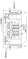
- FIG. 1 is a perspective view showing the appearance of the entire local air conditioning system of this example.
- FIG. 2 is a cross-sectional view of the overall configuration of the local air conditioning system of the present example.
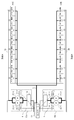
- FIG. 3 is an example of arrangement
- FIG. 4 is a detailed structural example in the local air conditioning system of this example, (a) is a detailed structural example of the local air conditioner 10, (b) is a detailed structural example of the cold-heat source unit 20.
- FIG. 4 is a detailed structural example in the local air conditioning system of this example, (a) is a detailed structural example of the local air conditioner 10, (b) is a detailed structural example of the cold-heat source unit 20.
- FIG. 4 is a detailed structural example in the local air conditioning system of this example, (a) is a detailed structural example of the local air conditioner 10, (b) is a detailed structural example of the cold-heat source unit 20.
- FIG. 4 is a detailed structural example in the local air conditioning system of this example, (a) is a detailed structural example of the local air conditioner 10, (b) is a detailed structural example of the cold-heat source unit 20.
- FIG. 4 is a detailed structural example in the local air conditioning system of this example, (a) is a detailed structural example of the local air conditioner 10,
- FIGS. 1 to 4 substantially the same components are denoted by the same reference numerals.
- the local air conditioning system of this example basically cools a specific cooling target space (such as the cold air space S shown) by a plurality of local air conditioners 10, and the entire cold air space S has a predetermined temperature It is controlled to keep in
- the cold air space S is a space between two rack rows (a space between the rack row 1 a and the rack row 1 b) as shown in FIGS. 1 and 2.
- one local air conditioning system is provided corresponding to one cold air space S.
- the rack row 1a is formed by arranging a plurality of equipment storage racks 1 in one row. Similarly, in the rack row 1b, a plurality of equipment storage racks 1 are arranged in one row. An electronic device 9 and the like (FIG. 2) are accommodated in each equipment accommodation rack 1.
- a plurality of local air conditioners 10 are installed above each of the rack rows.
- eight local air conditioners 10 are installed for the rack row 1a, and eight local air conditioners 10 are similarly installed for the rack row 1b. is set up.
- the former is referred to as a local air conditioner group of row A, and the latter is referred to as a local air conditioner group of row B.
- cold heat source unit 20 is provided for each row (for each group of local air conditioners in each row). That is, the illustrated cold-heat source unit 20a is provided for the row A local air conditioner group, and the illustrated cold-heat source unit 20b is provided for the local air conditioner group B.
- the cold heat source unit 20a supplies the refrigerant to all the eight local air conditioners 10 of the local air conditioner group in the A row via the refrigerant pipe 2a.
- the cold heat source unit 20b also supplies the refrigerant to all eight local air conditioners 10 of the local air conditioner group in row B via the refrigerant pipe 2b. That is, there are two systems for refrigerant supply.
- the cold heat source units 20a and 20b have substantially the same configuration, and in FIG. 1 and FIG. That is, the cold heat source unit 20 includes two pumps 21-1 and 21-2, inverters 22-1 and 22-2 for controlling the respective pumps 21, and a condenser 24 and the like. In practice, as shown in FIG. 4, a receiver tank 23 is further provided.
- the pump 21 is a refrigerant pump that pumps a refrigerant.
- the cold heat source unit 20 fails
- the refrigerant supply system also fails, and all the local air conditioners 10 related to this refrigerant supply system substantially stop functioning.
- the local air conditioning system of this example since the local air conditioning system of this example has two refrigerant supply systems, it will be described later unless the two systems do not function at the same time (the possibility is extremely low). It becomes possible to cope with the control processing of the controller 30. The details will be described later with reference to a flowchart showing control processing of the controller 30 and the like.
- one controller 30 is provided to control the entire one local air conditioning system corresponding to the one cold air space S. That is, the controller 30 includes all the local air conditioners 10 (here, 16 units of A row and B row together) and the two cold heat source units 20a and 20b for each row, and the communication lines 3 and 4 (see FIG. Control via 3). As for the cold heat source unit 20, the inverter 22 is mainly controlled via the communication line 4. Each local air conditioner 10 communicates with the local controller 13 shown in FIG. 4A via the communication line 3 to instruct, and the local controller 13 executes control according to the instruction (details will be given later with FIG. 4) explain).
- each local air conditioner 10 has an evaporator 11, a blower 12 and the like as a schematic configuration shown.
- the detailed configuration of each local air conditioner 10 will be described later with reference to FIG. 4 (a).
- the configuration itself of the local air conditioner 10 may be substantially the same as that of the related art.
- the configuration of the cold heat source unit 20 may be substantially similar to that of the related art. Therefore, these descriptions shall be simplified.
- coolant is supplied to the evaporator 11 of each local air conditioning machine 10 via the refrigerant
- the refrigerant is supplied from the cold heat source unit 20a to the evaporator 11 of each of the local air conditioners 10 in the group A of the local air conditioner group via the refrigerant pipe 2a.
- the refrigerant is supplied from the cold heat source unit 20b to the evaporator 11 of each of the local air conditioners 10 of the local air conditioner group in the B row via the refrigerant pipe 2b.
- the cold air space S is the space between the two rows of racks, that is, the rack row 1a and the rack row 1b as described above, and the cold air sent into the cold air space S is a rack of the rack row 1a and the rack row 1b.
- each rack 1 of the rack row 1a and the rack row 1b the surface facing the cold air space S is referred to as the front, and the opposite side is referred to as the back.
- the back side space may be referred to as a warm air space.
- the illustrated indoor space is, for example, a computer room (server room or the like).
- rack rows are not limited to only two rows 1a and 1b, and may be three or more, but are not shown here.
- the local cooling system of this example cools a relatively narrow space (here, the cold air space S) in the indoor space where the electronic device 9 (server apparatus etc.) is installed, and maintains it at a predetermined temperature
- the server apparatus and the like do not go down due to their own heat generation.
- the local air conditioner 10 redundant. That is, it is considered to provide a spare local air conditioner 10.
- a total of 16 local air conditioners 10 are provided with eight local air conditioners 10 for each row A and B for one cold air space S, but the cold air space It is not necessary to use 16 units to maintain the temperature of S at a predetermined temperature. For example, it is sufficient to operate 10 units, and the remaining 6 units are made to stand by as spares.
- the refrigerant supply of the system having the failure is stopped, and even if all the local air conditioners 10 of this system fail, the other normal system If there is a spare local air conditioner 10, the operation may be started.
- a cooling system consisting of a local air conditioner (1) to a local air conditioner (8), a cold heat source unit 20a, a refrigerant pipe 2a and the like is denoted as a system A, and a local air conditioner (9) to a local area
- the cooling system consisting of the air conditioner (16), the cold heat source unit 20b, the refrigerant pipe 2b and the like may be referred to as a system B in some cases.
- the controller 30 communicates with a local controller 13 (to be described later) of each local air conditioner 10 through the communication line 3 to collect status data (such as temperature) A process of sending an air flow instruction, an operation start / stop instruction, etc. is performed. Similarly, conventionally, communication with the cold heat source unit 20 through the communication line 4 is performed, and processing such as collecting state data or sending some instruction (operation start / stop instruction, rotation number instruction etc.) Is going.
- a unique identification number here, referred to as a station number
- the controller 30 manages and controls each local air conditioner 10 using this station number.
- the feature of the present method lies in the redundant operation control of the local air conditioner 10.
- one or more spare local air conditioners 10 are substantially provided. This is, for example, if the number necessary to maintain the cold air space S at a predetermined temperature is P, the number of P + ⁇ ( ⁇ ; 1 or more) is installed in advance. Then, basically, the controller 30 controls each local air conditioner 10 so that the P (or more P) local air conditioners 10 are in the operating state.
- the local air conditioner 10 which is not in operation is in the "standby state".
- Standby state means, as an example, a state in which the fan (the blower 12) is in the stop state, but not limited to this, the fan is in the stop state and the refrigerant is also in the stop state (the main plug is stopped and the evaporator is 11 may mean that the refrigerant does not flow in).
- the latter example a refrigerant
- FIG. 4A shows a detailed configuration of the local air conditioner 10. However, since this configuration and basic control may be regarded as existing configurations, they will be briefly described.
- the local air conditioner 10 includes an evaporator 11, a blower 12 (fan), a local controller 13, a solenoid valve (main plug) 14, an electronic expansion valve 15, and the like.
- the evaporator 11 and the blower 12 (fan) are as described above and will not be described here.
- the local controller 13 communicates with the controller 30 via the communication line 3. Then, in accordance with, for example, an instruction from the controller 30 (operation / standby instruction, set temperature, set air volume, etc.), various controls for realizing this instruction are performed. For example, according to the operation / standby instruction, the operation state or the above-mentioned "standby state” is set. In the operating state, the solenoid valve (main plug) 14 is opened, and in the "standby state", the solenoid valve (main plug) 14 is closed. In the operation state, a set temperature, a set air volume, and the like are instructed. The opening degree (EEV opening degree) of the electronic expansion valve 15 is adjusted and controlled in accordance with the set temperature.
- an instruction from the controller 30 operation / standby instruction, set temperature, set air volume, etc.
- the cold air volume is controlled by controlling the rotational speed of the blower 12 (fan).
- data collection processing is also performed, for example, to measure the temperature (blowing temperature) near the illustrated outlet. Note that these controls themselves may be considered as existing controls, but the contents of the instructions are according to the present method. Details will be described later.
- the local controller 13 adjusts the cooling performance by controlling the amount of refrigerant supplied to the evaporator 11, for example. This is achieved, for example, by controlling the electronic expansion valve 15 based on the set temperature (set value of the blowout temperature) instructed from the controller 30, the above-mentioned blowout temperature, etc. Control the flow rate of the refrigerant sent to the evaporator 11). This is basically control for setting the blow-out temperature to the set temperature.
- the refrigerant is gasified by cooling air (warm air).
- the refrigerant supplied to the evaporator 11 comes out of the evaporator 11 as refrigerant gas and is returned to the cold heat source unit 20 via the refrigerant pipe 2.
- FIG. 4 (b) shows a configuration example of the cold heat source unit 20. This configuration itself may be regarded as an existing configuration and will be briefly described below.
- the cold heat source unit 20 includes the pump 21, the inverter 22, the condenser 24 described above, and the receiver tank 23 illustrated.
- Cold water is supplied to the condenser 24 from a configuration (not shown) via a cold water pipe or the like.
- the illustrated three-way valve is not particularly relevant to the present method and will not be described.
- a three-way valve is not necessarily required and may be a general valve.
- the refrigerant gas returned to the cold heat source unit 20 is cooled by the cold water in the condenser 24 and liquefied, and is stored in the receiver tank 23 (receiver).
- the receiver 23 is provided, even if the amount of refrigerant supplied to the evaporator 11 changes due to load fluctuation, the liquid level of the receiver 23 moves up and down to cope with the load.
- FIG. 1 and 3 show an example in which the refrigerant pump 21 has a redundant configuration, but in the example of FIG. 4B, there is one pump 21 for each system.
- the configuration of the cold heat source unit 20 is separately identified by a code for each system. That is, with regard to the system A related to the group of local air conditioners 10 in the A row, the cold source unit 20a is provided, and the cold source unit 20a includes the pump 21a, the inverter 22a, the condenser 24a, the receiver tank 23a and the like.
- the cold heat source unit 20b is provided, and the cold heat source unit 20b has the pump 21b, the inverter 22b, the condenser 24b, the receiver tank 23b, etc. .
- the controller 30 collects data from each local controller 13 at predetermined time intervals via the communication line 3.
- Data to be collected are, for example, temperature and humidity, EEV opening degree and the like.
- the collected data is stored in a unit management table (not shown) (example of data configuration of unit management table: station number of each local controller 13, existence / nonexistence, operation / standby state, normal / fault state, setting value, temperature / humidity) ⁇ EEV opening degree / system).
- a unit management table (example of data configuration of unit management table: station number of each local controller 13, existence / nonexistence, operation / standby state, normal / fault state, setting value, temperature / humidity) ⁇ EEV opening degree / system).
- a specific example of the unit management table will be described later with reference to FIGS.
- the controller 30 refers to the data of the unit management table, and is proportional to the sum (load) of the EEV opening degrees of the local air conditioners 10 in operation in each system (system A, system B).
- the above cycle is repeated, and cooling is performed by releasing the heat in the room through the evaporator 11 and the condenser 24.
- the local air conditioner redundant control of the first embodiment will be described first.
- one of pump 21a and pump 21b may fail, for example. If the pump 21a fails, all the local air conditioners 10 of the system A will not be supplied with the refrigerant, and thus will not function substantially. In addition, although not described one by one, in the case of a system where such a pump failure or the like has occurred, control is substantially made to stop all local air conditioners 10 which were operating (for example, the above standby state). The controller 30 does this.
- the local air conditioner redundancy control of the first embodiment even if a failure occurs in which one of the two systems is suspended due to a pump failure, according to the local air conditioner redundancy control of the first embodiment, the possibility that the cold air space S can be maintained at a predetermined temperature Even if the cold air space S can not be maintained at a predetermined temperature, the temperature rise can be minimized to prevent the worst situation (such as server down).
- the controller 30 collects the operating / stopping states of the respective pumps 21a and 21b of the grids A and B, the states of the inverters 22a and 22b, the state of the refrigerant level, and the like in a predetermined cycle and stores them in the pump state table. Based on the collected data, it is determined whether the cold heat source unit 20 (the pump 21 thereof) of each system is normal or abnormal.
- the determination method may be arbitrary, but in the pump state table 40 in the example of FIG. 5 described later, if any one of the inverter 42 and the refrigerant level 43 is abnormal, for example, the determination 44 becomes abnormal.
- the controller 30 stops the operation of the cold heat source unit 20 (the pump 21 thereof) of the system for which the determination 44 has become abnormal, and sets the operation / stop state 41 as “stop”.
- the processing is performed, and the redundant operation in step S13 is performed as necessary. If both systems A and B are normal and one of the systems is abnormal, the operation stop and operation / stop state 41 are performed as described above after execution of the process of step S13 of FIG. 6 described later. The process to "stop” will be performed. Thereafter, if this state does not change, the determination in step S12 described later is the determination in (C) described later, and the operation is continued in this state.
- FIG. 5 shows an example of the data configuration of the pump state table 40. As shown in FIG. 5
- the illustrated pump state table 40 includes data items of the operation / stop state 41, the inverter 42, the refrigerant level 43, and the determination 44.
- the data of each of these data items is stored for each of the pump of system A and the pump of system B.
- the run / stop state 41 of the pump 21a is "run"
- the state 42 of the inverter 22a is "abnormal”
- the refrigerant level 43 is "normal”.
- the operation / stop state 41 of the pump 21a is "operation"
- the state 42 of the inverter 22a is "normal”
- the refrigerant level 43 is "normal”.
- the determination 44 is naturally "normal”.
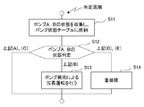
- controller 30 executes the process of FIG. 6 at a predetermined cycle.
- the process of FIG. 6 is a process of using the pump state table 40 or the like to determine whether or not to perform the redundant operation due to a pump abnormality.
- the controller 30 collects various data relating to the pump 21 from the respective cold source units 20a and 20b of the system A and the system B via the communication line 4, and collects the various data collected.
- the collected data (or the normal / abnormal determination result based on the collected data or the like) is stored in the operation / stop 41, the inverter 42, and the refrigerant level 43.
- step S12 based on the contents of the pump state table 40, it is determined whether or not the redundant operation due to the pump abnormality is to be performed (step S12). This is based on, for example, the judgment result (judgement 44) of the normality / abnormality of the pump and the operation / stop state 41, and the state of the pump is classified into any of the following (A) to (E) Branch the process according to the result.
- step S12 when it is classified into any of the following (A) and (C) in step S12, this processing is ended without processing as maintenance of the present condition.
- step S12 the redundant operation due to the pump abnormality is performed only when it is classified into the following (B) (step S13). The details of the process of step S13 will be described separately.
- step S14 it is determined that the major failure is present (step S14), and the present process is terminated.
- predetermined processing may be performed according to the serious failure determination, it is not described here because it is not relevant.
- step S13 is executed only in the case of this classification. That is, the system determined to be abnormal is shut down and alternate operation is performed in the normal system. Details will be described later.
- the example of the pump state table 40 shown in FIG. 6 corresponds to (B).
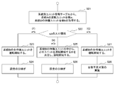
- FIG. 7 is a detailed flowchart of the process of step S13.
- the controller 30 has memorize
- the controller 30 has, for example, a CPU, a memory, a communication interface, etc. (not shown), and various data such as the above various tables 40, 50, 60 are stored in this memory, and a predetermined application program is made in advance. Is stored.
- the above-described various control processes and the like, and the processes of the flowcharts shown in FIG. 6, FIG. 7, and FIG. 10, etc. described above are executed by the CPU or the like (not shown) reading and executing this application program. It will be realized.
- the controller 30 collects information of each local air conditioner 10 of each system via the communication line 3 at predetermined intervals, and updates the unit management table 50 and the like as needed.
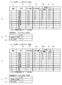
- FIG. 8 An example of the various tables 50, 60 is shown in FIG. 8 and will now be described with reference to FIG.
- the various tables 50 and 60 are provided separately for each system, and tables 50 and 60 for system A in FIGS. 8A and 8B and tables 50 for system B in FIGS. 8C and 8D, respectively. , 60.
- the tables for system A shown in FIGS. 8A and 8B may be referred to as a unit management table 50A and a system operation table 60A.
- the tables for system B shown in FIGS. 8C and 8D may be referred to as a unit management table 50B and a system operation table 60B.
- the station number 51 As shown in FIGS. 8A and 8C, in the unit management table 50, the station number 51, the state 52, the set temperature 53, the set air volume 54, and the measurement data 55 (EEV opening 55a, temperature 55b, ... etc. It consists of each data item such as.).
- the state 52 stores the state of each local air conditioner 10.
- the "state” is, for example, the presence / absence, the operation / standby, the presence / absence of abnormality, and the like.
- the set temperature of each local air conditioner 10 is stored in the set temperature 53. This may be set individually or may be set uniformly for each system.
- the system preset temperature 61 of the system operation table 60A of FIG. 8 (b) is set here. That is, the set temperature for the system set for each system is uniformly applied and set.
- the air volume '0' is naturally set for the local air conditioner 10 in the "standby” state. That is, the fan (fan 12) is stopped.
- the EEV opening 55a is also “0”, and the refrigerant is not supplied to the evaporator 11, but this is not a limitation. You may stop only).
- the local air conditioner 10 in an operating state may be referred to as a driving unit, and the local air conditioner 10 in a standby state may be referred to as a standby unit.
- FIG. 7 shows an example of processing when the pump of the system A is in abnormal operation while the pump of the system B is in normal operation.
- the number a of operation units of system A and the number b of standby units of system B are determined. That is, the number a of the local air conditioners 10 in the operating state in the system A where the pump abnormality has occurred and the number b of the local air conditioners 10 in the standby state in the normal system B are determined (step S21).
- the determination method of the local air conditioner 10 to start the operation may be various, and although not described in detail here, for example, it may be simply in the order of the station numbers or may be determined according to the temperature condition.
- the local air conditioner 10 (one or more candidates) to be started instead of the local air conditioner 10 is arbitrarily determined (for example, determined by a human) in advance. May be registered in an alternative operation setting table (not shown). In this case, it is natural to refer to this alternative operation setting table to determine the local air conditioner 10 which starts operation by alternative.
- priority may be determined.
- the priority order of the local air conditioners 10 located closer to the local air conditioner 10 to be substituted is set high.
- three alternative candidates for the local air conditioner (1) are to be registered, and when three local air conditioners (9), (10), and (11) are assumed to be three.
- the aircraft (9) has the highest priority, and the local air conditioner (11) has the lowest priority.
- the local air conditioner 10 for each local air conditioner 10 in advance, based on the positional relationship between the local air conditioner 10 and the other local air conditioners 10, when the local air conditioner 10 breaks down, it should be operated alternatively
- the local air conditioners are registered with priority.
- the priority may be determined according to the distance as described above, but is not limited thereto.
- another local air conditioner 10 of the same system is a substitute candidate.
- the local air conditioners (2), (3), etc. become alternative candidates.
- this method corresponds to the case where all the local air conditioners 10 of the system do not function due to a pump failure or the like, the local air conditioner 10 of another system is set as a substitute candidate.
- Steps S24 and S26 basically have substantially the same processing.
- the system setting temperature 61 which is the setting temperature as the system is set, and the individual setting 62 is set. It is The individual setting 62 is either “yes” or “none”, and is “none” in the illustrated example. When the individual setting 62 is "none", the set temperatures of all the local air conditioners 10 of the system are uniformly set to the value of the system set temperature 61.
- the system setting temperature 61 20.0 ° C., so all the locals of the system A as in the unit management table 50A shown in FIG. 8 (a)
- the set temperature 53 of the air conditioner is 20.0 ° C.
- the system setting temperature 61 21.0 ° C.
- the unit management table 50B The set temperature 53 of all the local air conditioners is 21.0 ° C.
- the set temperature 53 of each local air conditioner in the system can be set to any value individually. Even in this case, the set temperatures 53 of all the local air conditioners 10 are uniformly set to the value of the system set temperature 61 similarly to the case where the individual setting 62 is “none” by default, and then the set temperature is set.
- the set temperature 53 may be set to an arbitrary value only for the local air conditioner 10 where it is desired to individually set 53.
- the set air volume 54 may be substantially the same as the set temperature. That is, the set air volume 54 may be set to a uniform value in the system, or may be set individually for each local air conditioner 10.
- the setting handover process in steps S24 and S26 differs depending on whether the individual setting is "yes" or "no".
- the local air conditioner 10 (the local air conditioner 10 which was operating in the system A in the example of FIG. A standby unit that starts operation instead of this "original operation unit” will be called an "alternative unit".
- the "alternative unit” is always determined from among the (normal) standby units in the system where there is no pump failure.
- the "alternative unit” is determined from among the standby units in the system B.
- the set temperature of the “original operation unit” is set to the “substitutive unit” and is handed over.
- the setting value is acquired in the system-based unit management table 50, and thus acquired.
- this set-up temperature is higher than the "original operation unit” even if the "alternative unit” is operated if such takeover is not performed, there is a problem in maintaining the cooling target space at a predetermined temperature (It may not be a problem for the lower part).
- a system in which a pump failure occurs is referred to as an abnormal system, and a system in which a pump failure does not occur is sometimes referred to as a normal system.
- the lower one of the setting temperature of the abnormal system and the setting temperature of the normal system is set as the new system setting temperature of the normal system, and based on this, the setting of each local air conditioner 10 of the normal system Set the temperature 53.
- the system A is an abnormal system and the system B is a normal system
- the system setting temperature of the system A is 20.0 ° C. and the system setting temperature of the system B is 21. Since the temperature is 0 ° C., it is naturally 20.0 ° C. by comparing the two and judging the lower temperature.
- the system set temperature 61 is set to 20.0 ° C. in the system operation table 60B of the system B shown in FIG. 8D. Further, thereby, in the unit management table 50B of the system B shown in FIG. 8C, the set temperatures 53 of all the local air conditioners 10 are uniformly set to the value (20.0 ° C.) of the system set temperature 61. . Therefore, all the set temperatures 53 are 21.0 ° C. to 20.0 ° C. as illustrated. It is because it can be considered that there is no problem for the lower temperature.
- system operation table 60 how to decide the set temperature for each system (with / without individual setting, etc.) is arbitrarily determined by a designer / user or the like and set in advance (system operation table 60).
- step S28 the shortage countermeasure process of step S28 will be described in detail.
- measures such as “lowering the set temperature” and “increase the set air volume (increase the set air volume)” are basically performed. For example, both of the “lower the set temperature” and the “increase the set air volume (increase the set air volume)” may be performed, or only one of them may be performed.
- New set temperature current set temperature of each local air conditioner 53-P [° C] (B)
- the calculation formula of the new set temperature is as follows.
- New system set temperature 61 System set temperature 61-P [° C] As described above, when the system set temperature 61 changes, each set temperature 53 also changes uniformly.
- the target for determining and setting the new set temperature may be only the "alternative unit”, or may include not only the “alternative unit” but also the local air conditioner 10 which was operating in the normal system. It is also good.
- the maximum value (MAX air volume) of the air volume of the local air conditioner 10 is determined in advance, and the air volumes of all the local air conditioners 10 in a normal system (system B in this example) , MAX air flow.
- (B) The amount of increase in air volume is determined in advance according to the shortage. An example is given below.
- (C) Divide the deficient air volume between all the operating units (local air conditioners that were operating + "alternative unit”).
- the air flow increase amount is not calculated as the fixed value preset as described above, but is calculated according to the shortage of the air flow, the number of driving units, and the like.
- the air flow rate increase amount Q per one driving unit is calculated by the following formula.
- R the total value of the set air volume of the "original operation unit" without an alternative unit
- This air volume increase amount is added to the set air volume of each driving unit.
- the set air volume 54 of each standby unit is '0'
- the set air volume 54 is set to '40' at the same time as the existing operation unit when the operation is started. It shall be.
- the set air volume '40' is a predetermined value.
- the designer / user or the like arbitrarily determines and sets in advance which countermeasure should be taken (not taken). Further, as to the time to take measures, for example, it may be pre-set as one hour after the start of redundancy, and may be returned to the original set value when this time passes.
- 9A and 9B show the contents of the tables 50B and 60B related to the system B after execution of the countermeasure against the shortage of units in step S28 in the example shown in FIG.
- step S28 when the process of step S28 is performed, all standby units of the normal system (system B in this example) are started by the process of step S27. Therefore, the station number '5' that was the standby unit in FIG. Since four vehicles of '8' are started, as shown in FIG. 9 (a), all of these four states 52 become “drive”. Although not shown in the drawing, at this time, a predetermined set value ('40' in this example) is set to the set air volume 54 of these four units.
- the EEV opening degree is calculated and controlled on the side of the local controller 13 based on the set temperature and the current temperature (or the difference between these temperatures), other suction temperatures and control parameters. This is an existing technology and will not be described in particular.
- the processing of dividing the insufficient air volume in (2) and (c) above by the driving unit is performed as the above-mentioned “increase the air volume setting” process.
- the cold air space S can be maintained at a predetermined temperature even if the number is insufficient.
- 100% guarantee can not be made.
- the temperature rise in the cold air space S can be suppressed as much as possible, and the possibility of causing a serious failure such as a server device down can be extremely reduced.
- the refrigerant is supplied to the plurality of local air conditioners 10 by the common cold source unit 20.
- the required amount of refrigerant is supplied at the moment, but even if one local air conditioner 10 fails, when the standby unit in the same system is operated as a substitute, the number of operating units is Since there is no change, basically the required refrigerant supply amount will not change.
- the amount of refrigerant supplied by the cold heat source unit 20 is basically determined by the motor rotational speed of the pump 21.
- the motor rotation number of the pump 21 is inverter-controlled by the inverter 22, and the controller 30 controls the motor rotation number of the pump 21 by controlling the operating frequency of the inverter 22, thereby providing the refrigerant supply amount. Control. This is to calculate the operating frequency in the controller 30 based on the total value of the EEV opening. The formula for calculating the operating frequency is not particularly described.
- controller 30 controls the motor rotational speed of the pump 21 by the inverter 22 using the calculated new operating frequency to increase the supply amount of the refrigerant.
- a local air conditioning system in which one cold air space S is maintained at a predetermined temperature by two cooling systems each consisting of one refrigerant supply unit and a plurality of local air conditioners 10 Is proposed.
- this local air conditioning system when any one of the two cooling systems becomes abnormal due to a failure or the like of the refrigerant pump, the cold air can be operated by using the standby unit of the other normal system.
- the temperature of the space S can be maintained.
- the maintenance of the high temperature of the cool air space S can be realized by performing the handover of the setting.
- temperature maintenance of the cool air space S can be realized by executing the countermeasure process.
- one cold air space S is specified by two cooling systems each consisting of one refrigerant supply unit and a plurality of local air conditioners 10. It is a local air conditioning system that maintains the temperature. Therefore, the system configuration may be the configuration shown in FIGS. 1 to 4, and may also have a unit management table 50 for each system, a system operation table 60, etc. shown in FIG. Of course, these are not described here in particular.
- Example 1 corresponds to an abnormality as a whole of the system due to a failure or the like of the refrigerant pump.
- the second embodiment corresponds to the failure of the local air conditioner 10.
- the temperature of the cold air space S can be maintained by performing redundant operation.
- the above (A) is a state where the pumps 21 which are both refrigerant pumps of the systems A and B are operating normally, and one of the systems A and B is the above (C). Normal operation, the other is already stopped (only one system is operating).
- control of the controller 30 In any case, in a system operating normally, when there is one or more local air conditioners 10 in operation, and a failure occurs in any local air conditioner 10 in operation, control of the controller 30 To perform redundant operation.
- FIG. 10 shows a process flowchart relating to the redundant operation of the controller 30 in the second embodiment.
- the illustrated unit shall mean the local air conditioner 10.
- the unit management table 50 (50A, 50B) shown in FIG. 8 is referred to, and the contents of the table 50 are updated as needed.
- the controller 30 periodically communicates with the local controller 13 of each local air conditioner 10 via the communication line 3 to collect various information of each local air conditioner 10 (step S31).
- each local controller 13 has a self-check function and determines whether the own device is normal or abnormal.
- the information collected by the controller 30 includes the normality / abnormality.
- the controller 30 can determine the normality / abnormality of each local air conditioner 10 by referring to the collected information, and if all the local air conditioners 10 are normal (step S32, NO), this processing ends. Do.
- step S32 when there is an abnormality in one or more local air conditioners 10 (step S32, YES), first, in a system (referred to as own system) to which the local air conditioner 10 (referred to as a failure unit) to which this abnormality belongs It is determined whether there is a standby unit (step S33). If there is a standby unit (YES in step S33), a standby unit to start operation is determined (step S34). That is, the "alternative unit" for the faulty unit is determined.
- any standby unit among them is determined to be “alternative unit”.
- This determination method may be substantially the same as, for example, the method described in the above-mentioned step S 25, and for example, a table (alternative candidate or priority order is set) registered in advance in order of station number or temperature condition Determine the standby unit (alternative unit) to start operation with reference to.
- step S35 operation of this alternative unit is started, and setting handover processing is performed (step S35).
- the setting temperature of the failed unit is set as the setting temperature of the “alternative unit”, but the detailed description also shows the difference from the setting handover in step S39 described later. It shall be explained collectively later.
- step S33 is YES for the first and second ones out of the three failed units, and any standby unit is It is determined to be "alternative unit” (step S34), and the operation of "alternative unit” is started and the setting of the faulty unit is taken over by this "alternative unit” (step S35). Since step S33 is NO, the process proceeds to step S36 without executing steps S34 and S35.
- step S36 it is determined whether the number is insufficient. It is determined that the number is insufficient when step S33 is NO (step S36, YES). As described above, when “the number of failed units> the number of standby units”, the number is insufficient (including the case where there is no standby unit). If the number is not insufficient (step S36, NO), this process ends. In this case, the alternative operation can be realized by the standby unit in the own system, and it is not necessary to use the standby unit of another system.
- step S36 if the number is insufficient (step S36, YES), it is necessary to use standby units of other systems. However, if there is a pump abnormality in another system or there is no standby unit (step S37, NO), the standby unit of the other system can not be used, so step S40 is performed (in this case, step In S40, the answer is YES), and the shortage countermeasure process of step S41 is executed. Steps S40 and S41 will be described later.
- step S36, YES If only the own system is insufficient (step S36, YES) and the other systems are normal and there is one or more standby units (step S37, YES), the above-mentioned faulty unit is still an "alternative unit".
- step S38, S39 The same processing as the above-mentioned steps S34 and S35 is performed about the thing which is not decided (step S38, S39). That is, the "alternative unit" which is a standby unit to start operation in place of the faulty unit is determined (step S38).
- the determination method of the "alternative unit” may be the same as the method described above, and will not be described here. Then, operation of the "alternative unit” determined in step S38 is started, and setting handover processing is performed (step S39).
- step S35 since the standby unit in the same system as the faulty unit is set as the "alternative unit", the setting content of the faulty unit is handed over as it is.
- step S39 since the standby unit of the system different from the faulty unit is set as the "alternative unit", substantially the same process as the setting handover process in the first embodiment is performed. That is, in the case of "no individual setting", the lower one is adopted comparing the system preset temperature 61 of the system to which the faulty unit belongs and the system preset temperature 61 of the system to which the "alternative unit” belongs. It is assumed that a new system set temperature 61 of the system to which the alternative unit belongs. From this, this new system set temperature 61 becomes the set temperature 53 of the “alternative unit”.
- the set temperature 53 of the failed unit is set as the set temperature 53 of the “alternative unit”.
- steps S37 to S39 are repeatedly executed. This is substantially the same as repeated execution of the above steps S33 to S35, and if the determination in step S37 is YES for all the failed units, basically "alternative unit” is determined for all the failed units. The "alternative unit” will start operation. In this case, the determination in the next step S40, “Is the number of units insufficient?” Is NO, and this processing ends.
- step S37 determines whether there is also at least one faulty unit without an "alternative unit"
- step S40 determines whether there is also at least one faulty unit without an "alternative unit”. If there is also at least one faulty unit without an "alternative unit”, the determination in step S37 is NO, and the determination in step S40 is YES (the number of standby units is insufficient), and the shortage countermeasure process is executed. (Step S41).
- the shortage countermeasure process is executed (step S41).
- the shortage countermeasure process may be substantially the same as the shortage countermeasure process (the set temperature is lowered, the air volume is increased, etc.) in step S28, and will not be particularly described here.
- a plurality of local air conditioners 10 and a refrigerant supply unit for supplying refrigerant to each of the local air conditioners 10 with respect to an arbitrary space to be cooled (such as cold air space S)
- a local air conditioning system in which two cooling systems, each of which comprises the (cool source unit 20), are provided.
- a first cooling system (for example, the above system A) including a first refrigerant supply unit (for example, the cold heat source unit 20a) and a plurality of the local air conditioners 10 to which the refrigerant is supplied by the first refrigerant supply unit
- a second cooling system (for example, the above system) including a second refrigerant supply unit (for example, a cold source unit 20b) and a plurality of the local air conditioners 10 to which the refrigerant is supplied by the second refrigerant supply unit. B) are provided.
- the local air conditioner group according to the first cooling system and the local air conditioner group according to the second cooling system are different from each other, and overlap There is no.
- the local air conditioning system is basically a system for maintaining the space to be cooled at a desired temperature (a predetermined temperature set by a user or the like).
- both the first cooling system and the second cooling system are provided with one or more standby units.
- the standby unit in the other normal cooling system By starting the operation, it is possible to maintain the temperature of the space to be cooled at a desired temperature.
- the effect of maintaining the temperature of the space to be cooled to a desired temperature can be enhanced by passing the setting on the abnormal system side to the normal system side.
- the temperature setting of the local air conditioner 10 which was the operating unit in the cooling system in an abnormal state, is handed over to the temperature setting of the standby unit that starts the operation instead.
- lower preset temperatures may be applied to the normal grid side between the preset temperature on the abnormal grid side and the preset temperature on the normal grid side.
- the reason for maintaining the temperature of the space to be cooled to the desired temperature is to cool the heating element such as the server device, so even if the temperature of the space to be cooled becomes somewhat lower than the desired temperature It is not considered.
- the refrigerant pump breaks down
- the refrigerant pump in the case of a refrigerant supply unit having a redundant configuration of refrigerant pumps, for example, in the case of a refrigerant supply unit having two refrigerant pumps, the refrigerant pump is It means the case where both two have failed.
- the temperature of the space to be cooled can be maintained at a desired temperature by starting the standby operation of the standby unit.
- the standby unit to start this alternative operation is a standby unit of the same cooling system as the failed local air conditioner, but if there is no standby unit or if it is not enough, another cooling system standby unit is used. In this manner, the possibility of maintaining the temperature of the space to be cooled at a desired temperature can be increased.
- the space to be cooled is, for example, a space sandwiched by two rows of equipment mounting racks as shown in FIG. 1 to FIG. 3 etc.
- the local air conditioner group of the second cooling system is in a row corresponding to the other equipment mounting rack row, thereby forming a locality of the first cooling system.
- the air conditioner group and the local air conditioner group of the second cooling system are provided to face each other across the space to be cooled. Of course, it is not limited to such an example.
- the arbitrary space to be cooled (such as the cool air space S) is a space between two rack rows, and the local air conditioner 10 is provided above each rack row.
- a total of 16 local air conditioners 10 are provided, 8 for each rack row. That is, the two rows of local air conditioners 10 in rows A and B shown in the figure are provided, and each row consists of eight local air conditioners 10.
- 16 local air conditioners 10 are provided for one cooling target space, and the cooling target space is maintained at a predetermined temperature by these local air conditioners 10, but all 16 need to be operated. Rather, it has a redundant configuration.
- Some local air conditioners 10 are used as standby units as spare units.
- Each cold heat source unit 20a, 20b is provided with two pumps 21 for redundant operation, but when both pumps 21 fail in one of the cold heat source units 20, the local air conditioner 10 in that row All fail, so redundant operation (alternative operation) is performed by the local air conditioners 10 in the other row.
- the set temperatures of local air conditioners (1) to (8) are 20 ° C.
- the set temperature of the machines (9) to (16) is 21 ° C.
- the controller 30 is a standby unit in the row B and the local air conditioner (13) Among the units (16) to (16), for example, the local air conditioners (13) to (15) are started to operate instead of the local air conditioners (1) to (3). Furthermore, temperature setting etc. are performed. For example, there is a method of taking over the setting on the side of row A, and the temperature setting is set to 20 ° C. only for the local air conditioners (13) to (15). Alternatively, all the local air conditioners (9) to (15) may be set to the one with the lower temperature setting value. In this example, as described above, since the set temperature of row A is 20 ° C. and the set temperature of row B 21 ° C., the lower one of the temperature set values is 20 ° C., and all the local air conditioners (9) to (15) The set temperature of is 20 ° C.
- any one or more of the local air conditioners 10 fail, basically the standby unit in the same system is operated as a substitute, but if there is no standby unit or if there is not enough, the standby of another system It also uses a unit.
- the set temperature of row A is 20 ° C.
- the number of operating units 6 local air conditioners (1) to (6) are operating units and the rest are standby units
- setting of row B It is assumed that the system is operating at a temperature of 21 ° C. and the number of operating units 5 (local air conditioners (9) to (13) are operating units and the rest are standby units).
- the local air conditioners (1) to (3) in row A have failed.
- alternative operation is performed in the same row, but there are only two stand-by units for local air conditioners (7) and (8) for three unit failures, so one unit is missing.
- the controller 30 causes the local air conditioner (14) in row B to substitute for one of the operation shortages in row A.
- the set temperature may be set to 20 ° C. for only the local air conditioner (14), or all of 9 to 14 may be set to a lower temperature set value (20 ° C. in this example).
- a plurality of local air conditioners are installed in an arbitrary cooling target space, and a local air conditioner having a refrigerant supply unit for supplying the refrigerant to the plurality of local air conditioners
- a local air conditioner having a refrigerant supply unit for supplying the refrigerant to the plurality of local air conditioners
Landscapes
- Engineering & Computer Science (AREA)
- Physics & Mathematics (AREA)
- Thermal Sciences (AREA)
- General Engineering & Computer Science (AREA)
- Mechanical Engineering (AREA)
- Computer Hardware Design (AREA)
- Microelectronics & Electronic Packaging (AREA)
- Air Conditioning Control Device (AREA)
Abstract
Description
(A)両ポンプ正常運転:系統A,Bの両方とも、運転/停止状態41が“運転”且つ判定44が“正常”の場合が、この分類となる。
(B)一方は運転中異常発生、他方は正常運転:系統A,Bの両方とも運転/停止状態41は“運転”であるが、判定44はどちらか一方は“正常”で他方は“異常”の場合が、この分類となる。
(C)一方は正常運転、一方は既に停止:一方の系統は運転/停止状態41が“停止”となっており、他方の系統は運転/停止状態41が“運転”、且つ、判定44が“正常”の場合が、この分類となる。
(D)一方は運転中異常発生、一方は既に停止:一方の系統は運転/停止状態41が“停止”となっており、他方の系統は運転/停止状態41が“運転”、且つ、判定44が“異常”の場合が、この分類となる。
(E)両ポンプで運転中異常発生:系統A,Bの両方とも、運転/停止状態41が“運転”且つ判定44が“異常”の場合が、この分類となる。当然ながら、この場合も、重故障(冗長運転不能)とする。
(F) a=b:系統Bの全待機ユニットを運転開始する共に(ステップS23)、設定の引継ぎ処理を行う(ステップS24)。
(G) a>b:系統Bの全待機ユニットを運転開始すると共に(ステップS27)、台数不足対策処理を実行する(ステップS28)。すなわち、この場合、系統Bの待機ユニットを全て運転開始するが、系統Aの運転ユニット台数aに対し、系統Bの待機ユニット台数bが少ないため、台数不足が発生するので対策を行う。尚、図8の例では、上記の通り、a=5、b=4であるので、a>bであり、台数不足対策処理を実行することになる。
(H) a<b:系統Bの待機ユニットの中から、どのユニットを運転開始するかを決定し、運転を開始する(ステップS25)。そして、設定の引継ぎ処理を行う(ステップS26)。
例えば、予め設定温度の下げ幅を決めておく。つまり、所定値Pを設定しておく。そして、この所定値Pを用いて以下の算出式により新たな設定温度を決定・設定する(以下の通り、設定温度を所定値P分下げることになる)。
(b)個別設定なしの場合、新たな設定温度の算出式は以下の通りとなる。
上記の通り、系統設定温度61が変わることで各設定温度53も一律変わることになる。
これについては、例えば一例としては、
(a)一律、MAX風量にする。
(b)不足台数に応じて事前に、風量増加量を予め決めておく。一例を以下に記す。
不足台数=2~3台:風量増加量は+10
(但し、不足台数=4台以上の場合は、風量は一律でMAX風量とする)
尚、上記図8を用いた例では、不足台数は1台であり、図8(c)に示すように現在の設定風量は40であるので、新たな設定風量=40+5=45となる。これより、図9(a)に示すように、設定風量54は‘45’となっている。尚、図9については後に説明する。
(c)不足風量を全運転ユニット(運転中だった局所空調機+「代替ユニット」)で分割負担する。換言すれば、上記風量増加量を、上記のように予め設定される固定値とするのではなく、風量の不足分と運転ユニットの台数等に応じて、算出するものである。
ここで、R;代替ユニットが無い「もとの運転ユニット」の設定風量の合計値、
S;正常系統の全運転ユニットの台数(=正常系統で既に運転中であった台数+代替ユニットの台数)。換言すれば、正常系統における“もともとの運転台数”+“新たに運転を開始した台数”。
運転ユニット1台当たりの風量増加量Q = 40÷8=5となる。
Claims (9)
- 任意の冷却対象空間を冷却する局所空調システムにおいて、
第1の冷媒供給ユニットと、該第1の冷媒供給ユニットによって冷媒が供給される複数台の局所空調機から成る第1の冷却系統と、
第2の冷媒供給ユニットと、該第2の冷媒供給ユニットによって冷媒が供給される複数の局所空調機であって前記第1の冷却系統の局所空調機群とは異なる局所空調機群から成る第2の冷却系統とを設け、
通信線を介して全ての前記局所空調機と前記第1、第2の冷媒供給ユニットを管理制御する制御装置を備え、
該制御装置は、
運転状態の前記局所空調機を運転ユニット、待機状態の前記局所空調機を待機ユニットとし、前記各局所空調機がそれぞれ運転ユニット、待機ユニットのどちらであるかを記憶する記憶手段と、
前記第1、第2の冷媒供給ユニットの何れか一方に異常が発生した場合、他方の正常な冷却系統の前記局所空調機群のなかに前記待機ユニットがある場合には、該待機ユニットを異常発生した冷却系統の前記運転ユニットの代わりに運転状態とする代替運転ユニットとする冗長化運転制御手段と、
を有することを特徴とする局所空調システム。 - 前記冗長化運転制御手段は、前記代替運転ユニットの台数を、前記異常発生した冷却系統における運転ユニットの台数分とすると共に、前記運転ユニットの設定を前記代替運転ユニットに引き継がせることを特徴とする請求項1記載の局所空調システム。
- 前記冗長化運転制御手段は、前記代替運転ユニットの台数を、前記異常発生した冷却系統における運転ユニットの台数分とすると共に、前記2つの冷却系統の温度設定同士を比較して、より低い温度設定を前記正常な冷却系統の温度設定とすることを特徴とする請求項1記載の局所空調システム。
- 前記冗長化運転制御手段は、前記正常な冷却系統側に前記待機ユニットが無い場合、あるいは該待機ユニットの台数が前記異常発生した冷却系統における運転ユニットの台数よりも少ない場合には、該待機ユニット全てを前記代替運転ユニットとすると共に、前記正常な冷却系統における前記運転ユニット及び前記代替運転ユニットの設定温度を下げる又は/及び設定風量を増加する台数不足対策処理を実行することを特徴とする請求項1~3の何れかに記載の局所空調システム。
- 任意の冷却対象空間を冷却する局所空調システムにおいて、
第1の冷媒供給ユニットと、該第1の冷媒供給ユニットによって冷媒が供給される複数台の局所空調機から成る第1の冷却系統と、
第2の冷媒供給ユニットと、該第2の冷媒供給ユニットによって冷媒が供給される複数の局所空調機であって前記第1の冷却系統の局所空調機群とは異なる局所空調機群から成る第2の冷却系統とを設け、
通信線を介して全ての前記局所空調機と前記第1、第2の冷媒供給ユニットを管理制御する制御装置を備え、
該制御装置は、
運転状態の前記局所空調機を運転ユニット、待機状態の前記局所空調機を待機ユニットとし、前記各局所空調機がそれぞれ運転ユニット、待機ユニットのどちらであるかを記憶する記憶手段と、
任意の1台以上の前記局所空調機が故障した場合、該故障発生した局所空調機が属する前記冷却系統における前記待機ユニットを、該故障した運転ユニットの代わりに運転開始して代替運転ユニットとし、該待機ユニットが無い場合または足りない場合には、該故障発生した局所空調機が属しない前記冷却系統における前記待機ユニットを、該故障した運転ユニットの代わりに運転状態とする代替運転ユニットとする冗長化運転制御手段と、
を有することを特徴とする局所空調システム。 - 前記冷却対象空間は、2列の機器搭載ラック列に挟まれた空間であり、
前記第1の冷却系統の局所空調機群は何れか一方の機器搭載ラック列に対応して列を成し、前記第2の冷却系統の局所空調機群は他方の機器搭載ラック列に対応して列を成すことで、該第1の冷却系統の局所空調機群と該第2の冷却系統の局所空調機群とは前記冷却対象空間を挟んで対向して設けられることを特徴とする請求項1~5の何れかに記載の局所空調システム。 - 予め前記各局所空調機毎に、その局所空調機と他の局所空調機との位置関係に基づいて、その局所空調機が故障した場合に前記代替運転ユニットとすべき局所空調機を、1または複数登録しておき、複数登録する場合には優先順位を付して登録しておく第2の記憶手段を更に備え、
冗長化運転制御手段は、該第2の記憶手段に基づいて、前記代替運転ユニットを決定することを特徴とする請求項5記載の局所空調システム。 - 任意の冷却対象空間に対して局所空調機が複数台設置され、該局所空調機に対して冷媒供給する冷媒供給ユニットを備え、該各局所空調機と冷媒供給ユニットを通信線を介して制御する制御装置を更に備え、該各局所空調機と冷媒供給ユニットとによって前記冷却対象空間を冷却する局所空調システムにおける該制御装置であって、
前記冷媒供給ユニットとして第1の冷媒供給ユニットと第2の冷媒供給ユニットとを備え、前記第1の冷媒供給ユニットと該第1の冷媒供給ユニットによって冷媒を供給される複数台の前記局所空調機とから成る第1の冷却系統と、前記第2の冷媒供給ユニットと該第2の冷媒供給ユニットによって冷媒を供給される複数台の前記局所空調機とから成る第2の冷却系統とに対して、通信線を介して全ての前記局所空調機と前記第1、第2の冷媒供給ユニットを管理制御する制御手段を備え、
該制御手段は、
運転状態の前記局所空調機を運転ユニット、待機状態の前記局所空調機を待機ユニットとし、前記各局所空調機がそれぞれ運転ユニット、待機ユニットのどちらであるかを記憶する記憶手段と、
前記第1、第2の冷媒供給ユニットの何れか一方に異常が発生した場合、他方の正常な冷却系統の前記局所空調機群のなかに前記待機ユニットがある場合には、該待機ユニットを異常発生した冷却系統の前記運転ユニットの代わりに運転状態とする代替運転ユニットとする冗長化運転制御手段と、
を有することを特徴とする局所空調システムの制御装置。 - 任意の冷却対象空間に対して局所空調機が複数台設置され、該局所空調機に対して冷媒供給する冷媒供給ユニットを備え、該各局所空調機と冷媒供給ユニットを通信線を介して制御する制御装置を更に備え、該各局所空調機と冷媒供給ユニットとによって前記冷却対象空間を冷却する局所空調システムにおける該制御装置であって、
前記冷媒供給ユニットとして第1の冷媒供給ユニットと第2の冷媒供給ユニットとを備え、前記第1の冷媒供給ユニットと該第1の冷媒供給ユニットによって冷媒を供給される複数台の前記局所空調機とから成る第1の冷却系統と、前記第2の冷媒供給ユニットと該第2の冷媒供給ユニットによって冷媒を供給される複数台の前記局所空調機とから成る第2の冷却系統とに対して、通信線を介して全ての前記局所空調機と前記第1、第2の冷媒供給ユニットを管理制御する制御手段を備え、
該制御手段は、
運転状態の前記局所空調機を運転ユニット、待機状態の前記局所空調機を待機ユニットとし、前記各局所空調機がそれぞれ運転ユニット、待機ユニットのどちらであるかを記憶する記憶手段と、
任意の1台以上の前記局所空調機が故障した場合、該故障発生した局所空調機が属する前記冷却系統における前記待機ユニットを、該故障した運転ユニットの代わりに運転開始して代替運転ユニットとし、該待機ユニットが無い場合または足りない場合には、該故障発生した局所空調機が属しない前記冷却系統における前記待機ユニットを、該故障した運転ユニットの代わりに運転状態とする代替運転ユニットとする冗長化運転制御手段と、
を有することを特徴とする局所空調システムの制御装置。
Priority Applications (2)
| Application Number | Priority Date | Filing Date | Title |
|---|---|---|---|
| CN201080060856.8A CN102713450B (zh) | 2010-03-17 | 2010-11-02 | 局部空调系统和其控制装置 |
| JP2012505445A JP5440689B2 (ja) | 2010-03-17 | 2010-11-02 | 局所空調システム、その制御装置 |
Applications Claiming Priority (2)
| Application Number | Priority Date | Filing Date | Title |
|---|---|---|---|
| JP2010-060262 | 2010-03-17 | ||
| JP2010060262 | 2010-03-17 |
Publications (1)
| Publication Number | Publication Date |
|---|---|
| WO2011114573A1 true WO2011114573A1 (ja) | 2011-09-22 |
Family
ID=44648692
Family Applications (1)
| Application Number | Title | Priority Date | Filing Date |
|---|---|---|---|
| PCT/JP2010/069524 Ceased WO2011114573A1 (ja) | 2010-03-17 | 2010-11-02 | 局所空調システム、その制御装置 |
Country Status (3)
| Country | Link |
|---|---|
| JP (1) | JP5440689B2 (ja) |
| CN (1) | CN102713450B (ja) |
| WO (1) | WO2011114573A1 (ja) |
Cited By (2)
| Publication number | Priority date | Publication date | Assignee | Title |
|---|---|---|---|---|
| JP2014190563A (ja) * | 2013-03-26 | 2014-10-06 | Ntt Facilities Inc | 空調システム |
| WO2025126511A1 (ja) * | 2023-12-13 | 2025-06-19 | 株式会社デンソーテン | ディスプレイ装置及び情報処理装置 |
Families Citing this family (5)
| Publication number | Priority date | Publication date | Assignee | Title |
|---|---|---|---|---|
| TWI573968B (zh) * | 2014-10-24 | 2017-03-11 | Chunghwa Telecom Co Ltd | 空調控制系統及其方法 |
| CN105783210B (zh) * | 2014-12-26 | 2019-07-26 | 广州地铁设计研究院股份有限公司 | 一种应用于地铁车站的多联机空调系统及其控制方法 |
| CN109442677B (zh) * | 2018-09-18 | 2022-09-09 | 平安科技(深圳)有限公司 | 空调系统的故障控制方法、电子设备 |
| CN110410930A (zh) * | 2019-07-26 | 2019-11-05 | 广东美的制冷设备有限公司 | 空调的控制方法、系统及空调 |
| CN112503722B (zh) * | 2020-12-07 | 2021-12-31 | 珠海格力电器股份有限公司 | 设备的联动控制方法、系统、计算机设备和存储介质 |
Citations (6)
| Publication number | Priority date | Publication date | Assignee | Title |
|---|---|---|---|---|
| JPH0323734U (ja) * | 1989-07-18 | 1991-03-12 | ||
| JP2003065588A (ja) * | 2001-08-27 | 2003-03-05 | Hitachi Ltd | 空気調和装置 |
| JP2006064254A (ja) * | 2004-08-25 | 2006-03-09 | Ntt Power & Building Facilities Inc | 空調機監視システム、および空調機監視方法 |
| JP3842631B2 (ja) * | 2001-11-30 | 2006-11-08 | 高砂熱学工業株式会社 | 通信・情報処理機器室等の空調システム |
| JP2006308212A (ja) * | 2005-04-28 | 2006-11-09 | Shimizu Corp | 空調システムおよびその運転方法 |
| JP2010216776A (ja) * | 2009-03-18 | 2010-09-30 | Fuji Electric Systems Co Ltd | 局所空調システム、その制御装置、プログラム |
Family Cites Families (15)
| Publication number | Priority date | Publication date | Assignee | Title |
|---|---|---|---|---|
| US6034873A (en) * | 1998-06-02 | 2000-03-07 | Ericsson Inc | System and method for separating air flows in a cooling system |
| JP2001068881A (ja) * | 1999-08-26 | 2001-03-16 | Pfu Ltd | 電子機器における冷却ファンの制御方法および電子機器における冷却装置 |
| JP4558177B2 (ja) * | 2000-11-20 | 2010-10-06 | 高砂熱学工業株式会社 | 通信機器室等の空調システム |
| JP4422935B2 (ja) * | 2001-11-06 | 2010-03-03 | 三菱電機株式会社 | 空調システム |
| US7106590B2 (en) * | 2003-12-03 | 2006-09-12 | International Business Machines Corporation | Cooling system and method employing multiple dedicated coolant conditioning units for cooling multiple electronics subsystems |
| JP4302593B2 (ja) * | 2004-08-25 | 2009-07-29 | 株式会社Nttファシリティーズ | 空調機監視システム、および空調機監視方法 |
| JP4860301B2 (ja) * | 2006-03-02 | 2012-01-25 | ダブル・アイ・テー・ジャパン株式会社 | 空調システム |
| JP5243092B2 (ja) * | 2008-04-21 | 2013-07-24 | 株式会社Nttファシリティーズ | ラック型空調機 |
| JP2010043817A (ja) * | 2008-08-18 | 2010-02-25 | Fuji Denki Sosetsu Co Ltd | サーバ室の空調システム |
| JP5669348B2 (ja) * | 2008-08-26 | 2015-02-12 | 高砂熱学工業株式会社 | 電子通信機器室の冷却システム |
| JP5296457B2 (ja) * | 2008-08-27 | 2013-09-25 | 高砂熱学工業株式会社 | 空調システム |
| JP2010061446A (ja) * | 2008-09-04 | 2010-03-18 | Gac Corp | サーバークーラーシステム |
| CN201297710Y (zh) * | 2008-12-05 | 2009-08-26 | 珠海格力电器股份有限公司 | 电信中继站机房专用空调机组 |
| JP5290044B2 (ja) * | 2009-05-11 | 2013-09-18 | 株式会社Nttファシリティーズ | 空調機監視システム、および空調機監視方法 |
| US20110016893A1 (en) * | 2009-07-23 | 2011-01-27 | Warwick Graham Andrew Dawes | Redundant Cooling Method and System |
-
2010
- 2010-11-02 CN CN201080060856.8A patent/CN102713450B/zh not_active Expired - Fee Related
- 2010-11-02 JP JP2012505445A patent/JP5440689B2/ja not_active Expired - Fee Related
- 2010-11-02 WO PCT/JP2010/069524 patent/WO2011114573A1/ja not_active Ceased
Patent Citations (6)
| Publication number | Priority date | Publication date | Assignee | Title |
|---|---|---|---|---|
| JPH0323734U (ja) * | 1989-07-18 | 1991-03-12 | ||
| JP2003065588A (ja) * | 2001-08-27 | 2003-03-05 | Hitachi Ltd | 空気調和装置 |
| JP3842631B2 (ja) * | 2001-11-30 | 2006-11-08 | 高砂熱学工業株式会社 | 通信・情報処理機器室等の空調システム |
| JP2006064254A (ja) * | 2004-08-25 | 2006-03-09 | Ntt Power & Building Facilities Inc | 空調機監視システム、および空調機監視方法 |
| JP2006308212A (ja) * | 2005-04-28 | 2006-11-09 | Shimizu Corp | 空調システムおよびその運転方法 |
| JP2010216776A (ja) * | 2009-03-18 | 2010-09-30 | Fuji Electric Systems Co Ltd | 局所空調システム、その制御装置、プログラム |
Cited By (2)
| Publication number | Priority date | Publication date | Assignee | Title |
|---|---|---|---|---|
| JP2014190563A (ja) * | 2013-03-26 | 2014-10-06 | Ntt Facilities Inc | 空調システム |
| WO2025126511A1 (ja) * | 2023-12-13 | 2025-06-19 | 株式会社デンソーテン | ディスプレイ装置及び情報処理装置 |
Also Published As
| Publication number | Publication date |
|---|---|
| JPWO2011114573A1 (ja) | 2013-06-27 |
| CN102713450B (zh) | 2014-10-08 |
| CN102713450A (zh) | 2012-10-03 |
| JP5440689B2 (ja) | 2014-03-12 |
Similar Documents
| Publication | Publication Date | Title |
|---|---|---|
| JP5290044B2 (ja) | 空調機監視システム、および空調機監視方法 | |
| WO2011114573A1 (ja) | 局所空調システム、その制御装置 | |
| JP4421423B2 (ja) | 空調機監視システム、および空調機監視方法 | |
| US6182742B1 (en) | Cooling apparatus for use in an electronic system | |
| JP4630356B2 (ja) | 空調設備とict機器の連係制御方法 | |
| CN102483644B (zh) | 信息处理系统的运用管理方法及信息处理系统 | |
| US20130317654A1 (en) | Air-conditioning control system and air-conditioning control method | |
| CN104748324B (zh) | 在数据中心内控制空调单元的方法和设备 | |
| JP5268072B2 (ja) | 空調制御システム及びその運転方法 | |
| CN102971588A (zh) | 计算机室空调系统和其冗余控制器 | |
| JP7047305B2 (ja) | 空気調和装置 | |
| WO2012020495A1 (ja) | 局所空調システム、その制御装置、プログラム | |
| JP2010216776A (ja) | 局所空調システム、その制御装置、プログラム | |
| CN109982546B (zh) | 一种微模块数据中心、控制方法及装置 | |
| CN112833518A (zh) | 一种用于数据中心的空调控制系统 | |
| CN114183882A (zh) | 制冷机组控制方法、装置、电子设备及存储介质 | |
| JP5415201B2 (ja) | 空調システム、その制御装置 | |
| CN201297710Y (zh) | 电信中继站机房专用空调机组 | |
| JP6598986B2 (ja) | 空調システム、空調制御方法およびプログラム | |
| CN115788920B (zh) | 多水泵的切换方法、设备及计算机可读存储介质 | |
| CN118856446A (zh) | 核电厂暖通系统、核电厂暖通调节方法 | |
| JP4688112B2 (ja) | Ict機器とファシリティの連係制御システム及び連係制御方法 | |
| JP4905992B2 (ja) | ラック型空調機及びその運転方法 | |
| CN115451524B (zh) | 故障处理方法、装置、电子设备和计算机可读存储介质 | |
| JP2011220585A (ja) | サーバ室用空調システム |
Legal Events
| Date | Code | Title | Description |
|---|---|---|---|
| WWE | Wipo information: entry into national phase |
Ref document number: 201080060856.8 Country of ref document: CN |
|
| 121 | Ep: the epo has been informed by wipo that ep was designated in this application |
Ref document number: 10847979 Country of ref document: EP Kind code of ref document: A1 |
|
| WWE | Wipo information: entry into national phase |
Ref document number: 2012505445 Country of ref document: JP |
|
| NENP | Non-entry into the national phase |
Ref country code: DE |
|
| 122 | Ep: pct application non-entry in european phase |
Ref document number: 10847979 Country of ref document: EP Kind code of ref document: A1 |