WO2011111718A1 - 圧縮成形装置、及び金型 - Google Patents
圧縮成形装置、及び金型 Download PDFInfo
- Publication number
- WO2011111718A1 WO2011111718A1 PCT/JP2011/055421 JP2011055421W WO2011111718A1 WO 2011111718 A1 WO2011111718 A1 WO 2011111718A1 JP 2011055421 W JP2011055421 W JP 2011055421W WO 2011111718 A1 WO2011111718 A1 WO 2011111718A1
- Authority
- WO
- WIPO (PCT)
- Prior art keywords
- mold
- heat
- heat pipe
- compression molding
- raw material
- Prior art date
- Legal status (The legal status is an assumption and is not a legal conclusion. Google has not performed a legal analysis and makes no representation as to the accuracy of the status listed.)
- Ceased
Links
Images


Classifications
-
- B—PERFORMING OPERATIONS; TRANSPORTING
- B29—WORKING OF PLASTICS; WORKING OF SUBSTANCES IN A PLASTIC STATE IN GENERAL
- B29C—SHAPING OR JOINING OF PLASTICS; SHAPING OF MATERIAL IN A PLASTIC STATE, NOT OTHERWISE PROVIDED FOR; AFTER-TREATMENT OF THE SHAPED PRODUCTS, e.g. REPAIRING
- B29C33/00—Moulds or cores; Details thereof or accessories therefor
- B29C33/02—Moulds or cores; Details thereof or accessories therefor with incorporated heating or cooling means
-
- B—PERFORMING OPERATIONS; TRANSPORTING
- B29—WORKING OF PLASTICS; WORKING OF SUBSTANCES IN A PLASTIC STATE IN GENERAL
- B29C—SHAPING OR JOINING OF PLASTICS; SHAPING OF MATERIAL IN A PLASTIC STATE, NOT OTHERWISE PROVIDED FOR; AFTER-TREATMENT OF THE SHAPED PRODUCTS, e.g. REPAIRING
- B29C43/00—Compression moulding, i.e. applying external pressure to flow the moulding material; Apparatus therefor
- B29C43/32—Component parts, details or accessories; Auxiliary operations
- B29C43/36—Moulds for making articles of definite length, i.e. discrete articles
-
- B—PERFORMING OPERATIONS; TRANSPORTING
- B29—WORKING OF PLASTICS; WORKING OF SUBSTANCES IN A PLASTIC STATE IN GENERAL
- B29C—SHAPING OR JOINING OF PLASTICS; SHAPING OF MATERIAL IN A PLASTIC STATE, NOT OTHERWISE PROVIDED FOR; AFTER-TREATMENT OF THE SHAPED PRODUCTS, e.g. REPAIRING
- B29C43/00—Compression moulding, i.e. applying external pressure to flow the moulding material; Apparatus therefor
- B29C43/32—Component parts, details or accessories; Auxiliary operations
- B29C43/52—Heating or cooling
-
- F—MECHANICAL ENGINEERING; LIGHTING; HEATING; WEAPONS; BLASTING
- F16—ENGINEERING ELEMENTS AND UNITS; GENERAL MEASURES FOR PRODUCING AND MAINTAINING EFFECTIVE FUNCTIONING OF MACHINES OR INSTALLATIONS; THERMAL INSULATION IN GENERAL
- F16D—COUPLINGS FOR TRANSMITTING ROTATION; CLUTCHES; BRAKES
- F16D69/00—Friction linings; Attachment thereof; Selection of coacting friction substances or surfaces
-
- B—PERFORMING OPERATIONS; TRANSPORTING
- B29—WORKING OF PLASTICS; WORKING OF SUBSTANCES IN A PLASTIC STATE IN GENERAL
- B29C—SHAPING OR JOINING OF PLASTICS; SHAPING OF MATERIAL IN A PLASTIC STATE, NOT OTHERWISE PROVIDED FOR; AFTER-TREATMENT OF THE SHAPED PRODUCTS, e.g. REPAIRING
- B29C43/00—Compression moulding, i.e. applying external pressure to flow the moulding material; Apparatus therefor
- B29C43/32—Component parts, details or accessories; Auxiliary operations
- B29C43/36—Moulds for making articles of definite length, i.e. discrete articles
- B29C43/361—Moulds for making articles of definite length, i.e. discrete articles with pressing members independently movable of the parts for opening or closing the mould, e.g. movable pistons
- B29C2043/3615—Forming elements, e.g. mandrels or rams or stampers or pistons or plungers or punching devices
- B29C2043/3628—Forming elements, e.g. mandrels or rams or stampers or pistons or plungers or punching devices moving inside a barrel or container like sleeve
-
- B—PERFORMING OPERATIONS; TRANSPORTING
- B29—WORKING OF PLASTICS; WORKING OF SUBSTANCES IN A PLASTIC STATE IN GENERAL
- B29C—SHAPING OR JOINING OF PLASTICS; SHAPING OF MATERIAL IN A PLASTIC STATE, NOT OTHERWISE PROVIDED FOR; AFTER-TREATMENT OF THE SHAPED PRODUCTS, e.g. REPAIRING
- B29C33/00—Moulds or cores; Details thereof or accessories therefor
- B29C33/02—Moulds or cores; Details thereof or accessories therefor with incorporated heating or cooling means
- B29C33/04—Moulds or cores; Details thereof or accessories therefor with incorporated heating or cooling means using liquids, gas or steam
-
- B—PERFORMING OPERATIONS; TRANSPORTING
- B29—WORKING OF PLASTICS; WORKING OF SUBSTANCES IN A PLASTIC STATE IN GENERAL
- B29C—SHAPING OR JOINING OF PLASTICS; SHAPING OF MATERIAL IN A PLASTIC STATE, NOT OTHERWISE PROVIDED FOR; AFTER-TREATMENT OF THE SHAPED PRODUCTS, e.g. REPAIRING
- B29C45/00—Injection moulding, i.e. forcing the required volume of moulding material through a nozzle into a closed mould; Apparatus therefor
- B29C45/17—Component parts, details or accessories; Auxiliary operations
- B29C45/46—Means for plasticising or homogenising the moulding material or forcing it into the mould
- B29C45/56—Means for plasticising or homogenising the moulding material or forcing it into the mould using mould parts movable during or after injection, e.g. injection-compression moulding
- B29C45/561—Injection-compression moulding
-
- B—PERFORMING OPERATIONS; TRANSPORTING
- B29—WORKING OF PLASTICS; WORKING OF SUBSTANCES IN A PLASTIC STATE IN GENERAL
- B29L—INDEXING SCHEME ASSOCIATED WITH SUBCLASS B29C, RELATING TO PARTICULAR ARTICLES
- B29L2031/00—Other particular articles
- B29L2031/16—Frictional elements, e.g. brake or clutch linings
-
- B—PERFORMING OPERATIONS; TRANSPORTING
- B29—WORKING OF PLASTICS; WORKING OF SUBSTANCES IN A PLASTIC STATE IN GENERAL
- B29L—INDEXING SCHEME ASSOCIATED WITH SUBCLASS B29C, RELATING TO PARTICULAR ARTICLES
- B29L2031/00—Other particular articles
- B29L2031/34—Electrical apparatus, e.g. sparking plugs or parts thereof
- B29L2031/36—Plugs, connectors, or parts thereof
-
- F—MECHANICAL ENGINEERING; LIGHTING; HEATING; WEAPONS; BLASTING
- F16—ENGINEERING ELEMENTS AND UNITS; GENERAL MEASURES FOR PRODUCING AND MAINTAINING EFFECTIVE FUNCTIONING OF MACHINES OR INSTALLATIONS; THERMAL INSULATION IN GENERAL
- F16D—COUPLINGS FOR TRANSMITTING ROTATION; CLUTCHES; BRAKES
- F16D69/00—Friction linings; Attachment thereof; Selection of coacting friction substances or surfaces
- F16D69/04—Attachment of linings
- F16D2069/0425—Attachment methods or devices
- F16D2069/0491—Tools, machines, processes
Definitions
- the present invention relates to a compression molding apparatus and a mold.
- a brake friction member that brakes a vehicle is manufactured by putting a raw material into a mold and heating and pressing.
- a friction material that comes into contact with a disk or a brake drum that rotates together with an axle is pressed against a pressure plate or a rim.
- the friction material is a mixture of various materials combined with a binding material so as to exert a predetermined frictional force even in a severe use environment.
- thermoforming of the friction material in order to increase the thermal conductivity of the mold, for example, a heat pipe embedded in the mold has been devised (see, for example, Patent Document 1).
- the heat pipe is also used in other molding dies and snow melting devices (see, for example, Patent Documents 2 to 4).
- This invention is made
- the heat pipe built in the mold is wrapped with a heat insulating layer.
- a compression molding apparatus for forming a mold by feeding a raw material to the mold and heating and pressurizing the mold, the first mold forming a mold surrounding a region where the raw material is compression molded, and the mold A second mold for compressing the raw material put in the container, and a heat source part for supporting and heating the second mold, wherein the second mold has one end positioned on the heat source part side. And a heat pipe having the other end positioned on the pressing surface side that presses the raw material, and a heat insulating layer that wraps the heat pipe along the longitudinal direction of the heat pipe.
- the compression molding apparatus can be applied to, for example, thermoforming of a molding such as a friction material for a disc brake or a drum brake, and can be thermoformed by pressure-bonding the friction material to a pressure plate or a rim.
- a molding such as a friction material for a disc brake or a drum brake
- the mold is placed on a heat source unit such as a hot platen of a compression molding apparatus so that various shapes can be produced. Therefore, in order to efficiently transfer heat to the molding object, it is required to improve the thermal conductivity of the mold.
- the heat conductivity of the mold is improved by providing the mold with a heat pipe having one end positioned on the heat source side and the other end positioned on the pressing surface side that presses the object to be molded. ing.
- the compression molding apparatus has a heat insulating layer that wraps the heat pipe along the longitudinal direction of the heat pipe.
- the heat insulating layer is a space formed inside the second mold, and the space extends from the heat source side to the pressing surface and supports the pressing surface from behind. A part may be provided. If the mold is formed in this way, the inside of the mold that does not contribute to the temperature rise of the pressing surface is hollow, so that the pressing surface is efficiently heated by the heat pipe and moved by the heat pipe Heat is not wasted except for the temperature rise of the pressing surface, and efficient thermoforming becomes possible. Furthermore, since the pressing surface is supported by the support portion from behind, it can withstand the pressing force when pressing the workpiece.
- the second mold is a first member that forms the pressing surface, and a second member that is disposed between the first member and the heat source unit and supports the first member. And a first heat insulating material sandwiched between the first member and the second member, and a second heat insulating material sandwiched between the second member and the heat source unit.
- die is comprised separately from the 1st member which forms a press surface, and the other 2nd member other than that,
- a 2nd member is a 1st heat insulating material and a 2nd heat insulating material. Sandwiched. If the mold is formed in this way, the heat of the heat source part is transmitted to the first member by the heat pipe without being transmitted to the second member, and thus efficient thermoforming becomes possible.
- a gap for absorbing the amount of thermal expansion and contraction of the heat pipe may be provided on at least one end side of both ends of the heat pipe. If such a gap is provided, it is possible to prevent damage to the heat pipe due to expansion and contraction caused by a difference in coefficient of linear expansion due to a difference in use temperature between normal temperature and thermoforming of the heat pipe.
- the second mold includes a third member that forms the pressing surface, and a fourth member that is disposed between the third member and the heat source unit and supports the third member.
- a heat pipe arranged so as to straddle the region where the third member is disposed and the other region may be embedded. If the heat pipe is embedded in the fourth member in this way, the amount of heat radiated from the fourth member to the surroundings in the process of transferring heat from the heat source part to the third member via the fourth member is reduced. Therefore, the heat of the heat source part is effectively transmitted to the pressing surface.
- the present invention is a compression molding mold in which a raw material is charged into a mold and heated and pressed to form a mold, and a first mold that forms a mold surrounding a region where the raw material is compression molded And a second mold for compressing the raw material put in the mold, wherein the second mold has one end located on the heat source part side that supports and heats the second mold
- the heat pipe having the other end positioned on the pressing surface side that presses the raw material and a heat insulating layer that wraps the heat pipe along the longitudinal direction of the heat pipe may be included.
- the invention of the present application is a compression molding apparatus for charging a raw material into a mold and heating and pressurizing to form a first mold for forming a mold surrounding a region where the raw material is compression molded,
- a second mold for compressing the raw material placed in the mold, and a heat source part for supporting and heating the second mold, and the second mold forms the pressing surface.
- the heat pipe is embedded in the fourth member supporting the third member in this way, the heat of the heat source part transmitted to the pressing surface of the third member via the fourth member is the fourth member. Since heat is not easily radiated from the member to the surroundings, the heat of the heat source part is effectively transmitted to the pressing surface.
- the fourth member is a plate-like member disposed between the third member and the heat source part, and the fourth member includes the third member of the heat of the heat source part.
- the heat pipe extending along the surface supporting the third member is disposed by the third member so as to convey heat of the region other than the region where the member is disposed to the third member. It may be embedded in a state where it is arranged so as to straddle the region that is being used and the other region.
- a plate-like member arranged between the third member and the heat source part is embedded with a heat pipe that carries heat in a region other than the region where the third member is arranged to the third member Since the heat of the heat source part radiated to the surroundings gathers in the third member, the heat of the heat source part is effectively transmitted to the pressing surface.
- the third member is supported by a central portion of the fourth member, and the fourth member has the heat disposed so as to straddle the peripheral portion of the central portion and the central portion.
- a pipe may be embedded. If the heat pipe arranged so as to straddle the central part of the fourth member supporting the third member and the peripheral part thereof is embedded in the fourth member, the heat is radiated from the peripheral part to the surroundings. Since the heat of the heat source unit collects in the center, the heat of the heat source unit is effectively transmitted to the pressing surface.
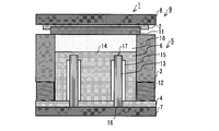
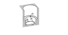
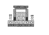
- FIG. 1 is a structural diagram of a compression molding apparatus 1 according to the first embodiment of the present invention.
- the compression molding apparatus 1 includes a mold 5 having a punch (second mold) 6 erected on an upper mold 2, a middle mold 3, and a lower mold 4, and a lower mold 4.
- a thermoforming device main body 9 having a lower heating plate (heat source part) 7 to which the punch 6 is fixed and an upper heating plate 8 to which the upper die 2 is fixed.
- the lower heating plate 7 and the upper heating plate 8 incorporate a heating heater (not shown).
- the heat of the lower heating plate 7 is transferred to the punch 6, and the heat of the upper heating plate 8 is transferred to the upper mold 2.
- the lower heating plate 7 is moved up and down by a hydraulic cylinder (not shown) so that the raw material of the friction material 10 put in the mold 5 can be molded.
- the mold 5 is a mold 5 for thermoforming the friction material of the brake pad of the disc brake, and the raw material of the friction material 10 is put into the mold frame formed by the middle mold (first mold) 3.
- the pressure plate 11 is placed on the middle mold 3 elastically supported by the spring member 12, and the lower mold 4 is raised and pressed.
- the punch 6 compresses the raw material of the friction material 10, and the pressure plate 11 eventually comes into contact with the upper die 2.
- the region where the friction material 10 of the pressure plate 11 is to be thermoformed is surrounded by the mold of the middle mold 3.
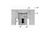
- the punch 6 has a heat pipe (first heat pipe) 13 as shown in FIG.
- One end of the heat pipe 13 is positioned near the lower end of the punch 6, and in other words, the other end of the punch 6 is positioned near the back of the pressing surface 14 that presses the friction material 10, in other words, near the upper end of the punch 6.
- a plurality of them are arranged in the vertical direction inside.
- the punch 6 has a heat insulating layer 15 that wraps the heat pipe 13 along the longitudinal direction of the heat pipe 13.
- the heat insulating layer 15 is an air layer. Since the heat insulating layer 15 is provided around the heat pipe 13, the heat that has entered the lower end 16, which is the lower end of the lower heat platen 7, is deprived by the punch 6 in the middle. It is transmitted to the upper end 17 as it is.
- the heat insulation layer 15 may adopt a configuration that suppresses heat conduction using not only a hollow air layer but also various materials having low heat conductivity.
- the heat pipe 13 encloses a volatile hydraulic fluid in the pipe, heat is instantaneously generated by repeating a cycle in which the hydraulic fluid evaporates and condenses in the non-heated portion when heated locally. Move to.
- the entire punch 6 is inevitably heated, so a long time is required to reach a large amount of heat and the target temperature, and the mold 5 is mainly composed of iron.
- heat conduction is very slow.
- the heat conductivity of the heat pipe 13 is 20000 to 40000 W / mK, whereas the heat conductivity of iron is about 84 W / mK.
- the heat transmitted from the lower end 16 in the heat pipe 13 spreads from the side surface of the heat pipe 13 to the punch 6 before reaching the upper end 17.
- the punch 6 according to the present embodiment is provided with the heat insulating layer 15, the heat received from the lower heating plate 7 at the lower end 16 of the heat pipe 13 does not escape from the side surface of the heat pipe 13 into the punch 6. It is transmitted to 17. Thereby, the heat of the lower heating board 7 moves to the pressing surface 14 efficiently.
- die 5 which concerns on this embodiment, even if it starts from a cold state, the press surface 14 is heated instantaneously and it can start thermoforming rapidly.
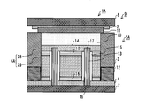
- FIG. 2 is a structural diagram of a compression molding apparatus 1A according to a first modification of the present embodiment.
- the compression molding apparatus 1 ⁇ / b> A has a die 5 ⁇ / b> A having a punch 6 ⁇ / b> A erected on an upper die 2, a middle die 3, and a lower die 4, and a punch 6 ⁇ / b> A fixed via the lower die 4.
- a thermoforming apparatus body 9 having an upper heating plate 8 to which the lower heating plate 7 and the upper mold 2 are fixed.
- the punch 6 ⁇ / b> A is disposed between an upper punch (first member) 28 that forms a pressing surface 14 that presses the friction material 10, and the upper punch 28 and the lower heating plate 7. Two members, a lower punch (second member) 29 to be supported, are provided. Further, the punch 6 ⁇ / b> A has a heat pipe 13 and a heat insulating layer 15 similarly to the punch 6. Further, heat insulating materials are disposed between the upper punch 28 and the lower punch 29 and between the lower punch 29 and the lower die 4, respectively.
- the lower heat insulating material which is the second heat insulating material sandwiched between the lower punch 29 and the lower heating plate 7, is used as the lower heat insulating material 18, and the first heat insulating material sandwiched between the upper punch 28 and the lower punch 29.
- the upper heat insulating material is called the upper heat insulating material 19.
- the punch 6A is configured by fastening these members, that is, the upper punch 28, the lower punch 29, the upper heat insulating material 19, and the lower heat insulating material 18 with bolts (not shown).
- the upper heat insulating material 19 and the lower heat insulating material 18 are materials that can withstand the pressing force during thermoforming, and are made of, for example, a composite material such as mica, glass, glass fiber, or silicon.
- the lower heat insulating material 18 prevents the heat of the lower heating plate 7 from diffusing into the lower punch 29 that is an intermediate portion of the punch 6A that does not require heating, thereby making it easier for the heat of the lower heating plate 7 to be transferred to the heat pipe 13.
- the upper heat insulating material 19 prevents the heat obtained from the heat pipe 13 from diffusing into the lower punch 29, thereby facilitating the heat of the heat pipe 13 to be transmitted to the pressing surface 14 of the upper punch 28. Since the punch 6A has a multi-layer structure composed of the upper punch 28, the lower punch 29, the upper heat insulating material 19 and the lower heat insulating material 18, the mold 5A according to the present modification can be pressed even when starting from a cold temperature state. The surface 14 is heated instantaneously and thermoforming can be started quickly.
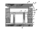
- FIG. 3 is a structural diagram of a compression molding apparatus 1B according to a second modification of the present embodiment.
- the compression molding apparatus 1 ⁇ / b> B has a die 5 ⁇ / b> B having a punch 6 ⁇ / b> B erected on an upper die 2, a middle die 3, and a lower die 4, and a punch 6 ⁇ / b> B fixed via the lower die 4.
- a thermoforming apparatus body 9 having an upper heating plate 8 to which the lower heating plate 7 and the upper mold 2 are fixed.
- the punch 6B has the heat pipe 13 and the heat insulating layer 15B in the same manner as the punch 6.
- the heat insulating layer 15B according to this modification like the heat insulating layer 15 described above, wraps the heat pipe 13 along the longitudinal direction of the heat pipe 13, but this layer is entirely inside the punch 6B. Has spread. That is, the heat insulating layer 15B forms a cavity inside the punch 6B. Since the cavity is formed inside the punch 6B, the heat capacity is reduced, heat is transferred from the lower end 16 to the upper end 17 of the heat pipe 13 without releasing heat, and the heat of the lower heating plate 7 is diffused. It becomes easy to be transmitted to the heat pipe 13 without. Since the punch 6B has a hollow structure, according to the mold 5B according to the present modification, the pressing surface 14 is instantaneously heated even when starting from a cold temperature state, and thermoforming can be started quickly.
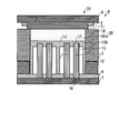
- the compression molding apparatus 1B has the support part 20 standingly arranged in the heat insulation layer 15B in order to suppress the bending of the press surface 14 at the time of shaping
- the support portion 20 may be columnar or plate-shaped. If the support part 20 is provided in the heat insulation layer 15B, it can endure the load added to the press surface 14 at the time of shaping
- the location, shape, number, and size of the support portion 20 are appropriately determined according to the size of the heat insulating layer 15B, the number of heat pipes 13, the load during molding, and the like. For example, there is another mode as shown in FIG.
- FIG. 6 is an enlarged view of the fixed state of the upper end 17 of the heat pipe 13 of the mold 5 according to the present embodiment.
- the heat pipe 13 is made of copper
- the punch 6 is made of iron, so that the thermal expansion coefficient of the heat pipe 13 is larger than that of the lower mold 4 and the punch 6. Therefore, the punch 6 is configured so that a gap 23A is formed between the upper end 17 of the heat pipe 13 and the opposing surface 22 of the punch 6 as shown in FIG.
- the vertical length of the gap 23A is the difference in the thermal expansion coefficient between the punch 6 and the heat pipe 13, the difference in linear expansion when the heat pipe 13 is heated from the normal temperature to the use temperature, and the length of the heat pipe 13.
- the thickness H between the opposing surface 22 of the punch 6 and the pressing surface 14 that opposes the upper end 17 of the heat pipe 13 is designed by appropriate strength calculation so as not to be deformed by compression molding.
- the punch 6 may use not only iron but also other iron-based materials (for example, steel materials and various alloys).
- the material of the heat pipe is not limited to copper, and for example, aluminum or stainless steel may be adopted.
- heat transfer grease may be injected into the gap 23A in order to maintain the thermal conductivity between the heat pipe 13 and the punch 6.
- the heat transfer grease is a viscous liquid mixed with copper powder or the like so that high thermal conductivity is exhibited, and is injected into the fitting portion 21 when the heat pipe 13 is assembled to the punch 6.
- an annular slit 25 may be provided at the edge of the facing surface 22, or the heat pipe 13 and the peripheral wall surface are intentionally provided without the slit 25. You may make it a clearance gap between 24. If the slit 25 is provided at the edge of the facing surface 22, as shown in FIG.
- the heat pipe 13 may be fixed as follows.
- FIG. 9 is an enlarged view of the fixed state of the lower end 16 of the heat pipe 13 of the mold 5 according to the present embodiment.
- the lower end 16 of the heat pipe 13 is configured such that a gap 23B is formed between the lower end 16 of the heat pipe 13 and the lower heating plate 7 as shown in FIG.
- the length of the gap 23B in the vertical direction is similar to the gap 23A in the difference in thermal expansion coefficient between the punch 6 and the heat pipe 13, the difference in linear expansion when the temperature of the heat pipe 13 is raised from the normal temperature to the use temperature, It determines suitably according to the length of the pipe 13, etc.
- a leaf spring 26 is inserted into the gap 23B.
- the leaf spring 26 biases the lower end 16 of the heat pipe 13 upward. Thereby, even if the heat pipe 13 and the punch 6 are thermally expanded, the adhesion between the upper end 17 of the heat pipe 13 and the facing surface 22 of the fitting portion 21, in other words, the upper end 17 of the heat pipe 13 and the punch 6 The thermal conductivity between is maintained.
- a spiral spring or a heat-resistant elastic member may be inserted.
- FIG. 10 shows another aspect of the compression molding apparatus 1A according to the first modification of the first embodiment.
- the compression molding apparatus 1A is illustrated here, it is the same also about the compression molding apparatus 1B which concerns on the compression molding apparatus 1 which concerns on 1st embodiment, and the 2nd modification of 1st embodiment.
- the compression molding apparatus 1 ⁇ / b> Ax according to this aspect includes a plate-like lower mold (fourth member) 4 x covering the lower heating plate 7 and a heat pipe (second heat pipe) 13 x in the lateral direction. Embedded. This heat pipe 13x collects the heat of a heating heater (not shown) built in the lower heating plate 7 to the punch 6A, thereby suppressing the heat radiation of the lower mold 4x.
- the heat pipe 13x has a punch so that the heat of the heating heater built in the lower heating plate 7 is concentrated on the punch 6A.
- the punch 6A extending along the surface supporting 6A is embedded in the lower mold 4x so as to straddle the region RI and the other region RO.
- the heat pipe 13x may have one end in the region RI and the other end in the region RO and straddle both regions, or both ends in the region RO and the region RI sandwiched between them. You may straddle.
- the region RI is a region where the punch 6A is disposed, and the pressure surface 14 of the punch 6A is heated when heated.
- the region RO is a region other than the region where the punch 6A is disposed, and is a region that radiates the heat of the lower heating plate 7 to the surrounding air.
- the position of the heat pipe 13x shown in FIG. 11 is merely an example, and the present invention is not limited to this, and may be disposed at any position as long as it straddles the region RI and the region RO. .
- the heat pipe 13x may be arranged so as to straddle each region RI where the punches 6A are arranged and the other region RO.
- the heat collecting effect on the punch 6A by horizontally embedding the heat pipe 13x in the lower mold 4x is independent of the presence or absence of the heat pipe 13 embedded in the punch 6A. That is, the compression molding apparatus 1Ax may omit the heat pipe 13 embedded in the punch 6A, for example. About the structure which excluded the heat pipe 13, it can apply similarly also when this aspect is applied about the compression molding apparatus 1B which concerns on 1st embodiment, and the compression molding apparatus 1B which concerns on a 2nd modification.
- FIG. 12 shows a mode in which the heat pipe 13y is embedded in the lower mold 4y in the lateral direction. As shown in FIG.
- the compression molding apparatus 1 y has a heat pipe (fourth member) 4 y with a heat pipe (instead of omitting the heat pipe 13 embedded in the punch 6 ⁇ / b> A).
- a second heat pipe 13y is embedded in the horizontal direction.
- the heat pipe 13y collects the heat of the lower heating plate 7 to the punch (third member) 6y.
- the position of the heat pipe 13y is the same as that shown in FIG. 11, and is embedded in the lower mold 4y so as to straddle the region RI where the punch 6y is disposed and the other region RO.
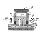
- FIG. 13 is a diagram showing heat transfer of the compression molding apparatus 1y according to this embodiment.
- the punch 6y is supported at the center of the lower mold 4y, and the heat pipe 13y is embedded in a state of being disposed across the center of the lower mold 4y, For example, as shown in FIG. 13, heat dissipation of the lower heating plate 7 radiated from the periphery of the punch 6y arranged on the lower mold 4y is suppressed. Since the heat pipe 13y has a property of transporting heat from a place with a high temperature to a place with a low temperature, the surrounding heat gathers in the punch 6y from which heat is taken away by repeatedly putting the friction material 10 into the mold 5.
- the horizontal heat pipe 13x and the vertical heat pipe 13 are not limited to those separate from each other.
- the heat pipe passes through the region RI from the region RO and then bends upward. It may be formed in an L shape such as being arranged inside.
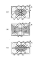
- FIG. 15A shows a case where only the heat pipe 13 is provided, in other words, a case where only the vertical heat pipe is provided. Moreover, what provided only the heat pipe 13x, in other words, what provided only the horizontal heat pipe is shown in FIG. Moreover, the thing of this modification which provided both the heat pipe 13 and the heat pipe 13x is shown in FIG.15 (C).
- FIGS. 15A to 15C only the punch and the lower die are shown, and the others are omitted.
- FIGS. 15 (A) to 15 (C) in the case where only the vertical heat pipe is provided, the heat of the lower heating plate is not collected to the punch, and thus the heat radiation amount of the lower die is large.
- the heat of the lower heating plate collects in the punch, but the heat radiation to the side between the punch pressing surface is large.
- the heat of the lower heating plate is efficiently collected on the pressing surface of the punch, and the heat radiation amount is small.
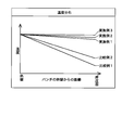
- FIG. 16 shows a mold having no heat pipe or a heat insulation layer (Comparative Example 1), a mold having a vertical heat pipe and no heat insulation layer (Comparative Example 2), a mold having a vertical heat pipe and a heat insulation layer.
- Example 16 in the case of Comparative Example 1, it can be seen that the temperature gradually decreases as the distance from the hot platen approaches the pressing surface. In the case of Comparative Example 2, it can be seen that the temperature decreases as in Comparative Example 1, although not as sharply as Comparative Example 1. On the other hand, in Examples 1 to 3, it can be seen that the temperature hardly decreases as the distance from the heating plate approaches the pressing surface. In particular, in the case of Example 3, it can be seen that the temperature does not significantly decrease even when compared with Example 1 or Example 2.
- the heat transport path follows the route of the hot platen, the inside of the punch, and the pressing surface.
- the heat transport path follows the route of hot platen-heat pipe-inside punch-pressing surface.
- the heat transport path follows the route of hot platen-heat pipe-pressing surface-inside the punch. That is, since the heat transfer to the inside of the punch is last, the temperature of the pressing surface is preferentially raised. Further, in the case of the second embodiment, the heat transport path follows the route of hot platen-lateral heat pipe-inside punch-pressing surface.
- the temperature of the pressing surface is preferentially raised. Therefore, even after the cold start, the pressing surface is instantaneously heated and thermoforming can be started quickly.
- the amount of heat released to the periphery of the lower mold is small, the heat of the hot plate is efficiently transmitted to the heat pipe, and the pressing surface is further preferentially heated.
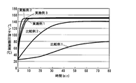
- FIG. 17 shows a graph of the temperature change until the temperature rise on the pressing surface is completed for Examples 1 to 3 and Comparative Examples 1 and 2 described above.
- the time until saturation at about 150 ° C. is about 10 minutes.
- the time until saturation at about 151 ° C. is about 12 minutes.
- the time until saturation at about 153 ° C. is about 5 minutes.
- Comparative Example 1 it takes about 80 minutes to saturate at about 80 ° C.
- Comparative Example 2 it takes about 50 minutes to saturate at about 140 ° C. Note that the set temperature of the hot platen when this experiment is performed is 160 ° C.
- Examples 1 to 3 have the following advantages because the temperature of the pressing surface is raised more instantaneously than Comparative Example 1 and Comparative Example 2. That is, as in Comparative Example 1 and Comparative Example 2, since the temperature rise is slow, if the difference between the temperature of the hot platen and the temperature of the pressing surface cannot be ignored, the pressing surface reaches a desired temperature and, for example, a friction material is used. In order to ascertain whether thermoforming is possible, it is necessary to take measures such as embedding a thermocouple in the punch and taking out the wiring from the lower mold. For this reason, replacement of the mold placed on the hot plate becomes extremely troublesome.
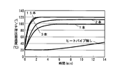
- FIG. 18 is a graph comparing the relationship between the number of heat pipes and the reachable temperature.
- the temperature (saturation temperature) reached when the number of heat pipes is about 1 or 2 is about 90 to 110 ° C.
- the temperature reached when there are 3 or more heat pipes is about 120 ° C. It turns out that it becomes.
- the set temperature of the hot plate at this time is 120 ° C.
- the number of heat pipes, the length, shape (cross section), and thickness (diameter) of the heat pipe can be appropriately determined according to the shape of the product to be manufactured, the rate of temperature increase, and the saturation temperature at which the mold temperature is stable. .
- the compression molding apparatus and the mold according to the present invention can be applied to efficient thermoforming of a molded object such as a friction material of a disc brake or a drum brake, and the friction material is applied to a pressure plate or a rim. Can be thermoformed by pressure bonding.
Landscapes
- Engineering & Computer Science (AREA)
- Mechanical Engineering (AREA)
- General Engineering & Computer Science (AREA)
- Casting Or Compression Moulding Of Plastics Or The Like (AREA)
- Moulds For Moulding Plastics Or The Like (AREA)
Priority Applications (2)
| Application Number | Priority Date | Filing Date | Title |
|---|---|---|---|
| CN201180013264.5A CN102791455B (zh) | 2010-03-09 | 2011-03-08 | 压缩成型设备和成型模 |
| US13/583,436 US9108341B2 (en) | 2010-03-09 | 2011-03-08 | Compression molding apparatus and molding die |
Applications Claiming Priority (4)
| Application Number | Priority Date | Filing Date | Title |
|---|---|---|---|
| JP2010-052115 | 2010-03-09 | ||
| JP2010052115 | 2010-03-09 | ||
| JP2011007861A JP5687503B2 (ja) | 2010-03-09 | 2011-01-18 | 圧縮成形装置、金型、及び摩擦材の製造方法 |
| JP2011-007861 | 2011-04-05 |
Publications (1)
| Publication Number | Publication Date |
|---|---|
| WO2011111718A1 true WO2011111718A1 (ja) | 2011-09-15 |
Family
ID=44563518
Family Applications (1)
| Application Number | Title | Priority Date | Filing Date |
|---|---|---|---|
| PCT/JP2011/055421 Ceased WO2011111718A1 (ja) | 2010-03-09 | 2011-03-08 | 圧縮成形装置、及び金型 |
Country Status (4)
| Country | Link |
|---|---|
| US (1) | US9108341B2 (enExample) |
| JP (1) | JP5687503B2 (enExample) |
| CN (1) | CN102791455B (enExample) |
| WO (1) | WO2011111718A1 (enExample) |
Cited By (2)
| Publication number | Priority date | Publication date | Assignee | Title |
|---|---|---|---|---|
| CN102431114A (zh) * | 2011-09-22 | 2012-05-02 | 山东金麒麟集团有限公司 | 一种盘式刹车片的生产方法 |
| CN102494065A (zh) * | 2011-11-29 | 2012-06-13 | 重庆红宇摩擦制品有限公司 | 鼓式摩擦材料的制造工艺 |
Families Citing this family (9)
| Publication number | Priority date | Publication date | Assignee | Title |
|---|---|---|---|---|
| CN103273606A (zh) * | 2013-06-18 | 2013-09-04 | 四川中邦模具有限公司 | 一种具有保温功能的电加热模压成型设备 |
| CN103317652A (zh) * | 2013-06-18 | 2013-09-25 | 四川中邦模具有限公司 | 能够防止蓄热体表面受到破坏的电加热模压成型设备 |
| EP2842711B1 (en) * | 2013-08-26 | 2018-10-10 | Airbus Operations GmbH | Apparatus and method for producing a composite material aircraft component |
| EP2862701B1 (en) | 2013-10-15 | 2020-04-08 | AIRBUS HELICOPTERS DEUTSCHLAND GmbH | Molding device |
| US9616482B2 (en) * | 2013-11-05 | 2017-04-11 | Martinrea Industries, Inc. | Hot forming metal die with improved cooling system |
| US9914275B1 (en) * | 2014-11-20 | 2018-03-13 | Akebono Brake Industry Co., Ltd. | Thermally-conductive hot press assembly |
| WO2017065715A1 (en) * | 2015-10-13 | 2017-04-20 | Floteks Plastik Sanayi Ve Ticaret Anonim Sirketi | A mold heating system which increases production speed for rotational molding technology |
| US10987831B2 (en) * | 2019-05-24 | 2021-04-27 | The Boeing Company | Dies for forming a part and associated systems and methods |
| CN112044169B (zh) * | 2020-08-12 | 2023-01-17 | 无锡市英波化工有限公司 | 一种环保内墙涂料工艺系统及其废料压滤处理工艺 |
Citations (6)
| Publication number | Priority date | Publication date | Assignee | Title |
|---|---|---|---|---|
| JPS6295210A (ja) * | 1985-10-23 | 1987-05-01 | Hitachi Ltd | プラスチツク成形用金型 |
| JPS63111024A (ja) * | 1986-10-29 | 1988-05-16 | Fuji Electric Co Ltd | 樹脂板成形用金型 |
| JPH0591820U (ja) * | 1992-05-15 | 1993-12-14 | 曙ブレーキ工業株式会社 | 摩擦パッド用熱プレス型 |
| JP2001018229A (ja) * | 1999-05-06 | 2001-01-23 | Ono Sangyo Kk | 合成樹脂成形用金型並びに金型温度調整装置及び金型温度調整方法 |
| JP2003291182A (ja) * | 2002-03-29 | 2003-10-14 | Mitsubishi Materials Corp | バルブゲート式金型装置 |
| JP2005138366A (ja) * | 2003-11-05 | 2005-06-02 | National Institute Of Advanced Industrial & Technology | 精密成形金型 |
Family Cites Families (10)
| Publication number | Priority date | Publication date | Assignee | Title |
|---|---|---|---|---|
| FR2459720A1 (fr) * | 1979-06-26 | 1981-01-16 | Solyvent Ventec Ste Lyon Venti | Ensemble de moule perfectionne pour le moulage des elastomeres |
| DE3811112A1 (de) * | 1988-03-31 | 1989-10-12 | Fritz Mueller | Spritzgussverfahren fuer kunststoffe und spritzgussform |
| US5516470A (en) * | 1991-03-05 | 1996-05-14 | Aga Aktiebolag | Method of tempering a molding tool |
| SE9100663L (sv) * | 1991-03-05 | 1992-05-04 | Toolvac Engineering Ab | Foerfarande foer kylning av ett formverktyg |
| JPH0591820A (ja) | 1991-10-02 | 1993-04-16 | Idemitsu Kosan Co Ltd | 植物の栽培方法 |
| JP2837990B2 (ja) | 1992-06-09 | 1998-12-16 | 株式会社リコー | プラスチック成形用金型の冷却装置 |
| JP3381451B2 (ja) * | 1995-04-06 | 2003-02-24 | ジェイエスアール株式会社 | 成形用金型、成形方法、成形材料、及び成形品 |
| JPH11350411A (ja) | 1998-06-09 | 1999-12-21 | Fujikura Ltd | 地熱および補助熱源を利用したヒートパイプ式道路融雪装置 |
| DE19829429C2 (de) * | 1998-07-01 | 2001-10-31 | Contitech Vibration Control | Heizpresse zur Herstellung von elastomeren Formteilen |
| CN101337413A (zh) * | 2001-11-06 | 2009-01-07 | 北川精机株式会社 | 压制装置及压制装置的控制方法 |
-
2011
- 2011-01-18 JP JP2011007861A patent/JP5687503B2/ja not_active Expired - Fee Related
- 2011-03-08 CN CN201180013264.5A patent/CN102791455B/zh not_active Expired - Fee Related
- 2011-03-08 WO PCT/JP2011/055421 patent/WO2011111718A1/ja not_active Ceased
- 2011-03-08 US US13/583,436 patent/US9108341B2/en not_active Expired - Fee Related
Patent Citations (6)
| Publication number | Priority date | Publication date | Assignee | Title |
|---|---|---|---|---|
| JPS6295210A (ja) * | 1985-10-23 | 1987-05-01 | Hitachi Ltd | プラスチツク成形用金型 |
| JPS63111024A (ja) * | 1986-10-29 | 1988-05-16 | Fuji Electric Co Ltd | 樹脂板成形用金型 |
| JPH0591820U (ja) * | 1992-05-15 | 1993-12-14 | 曙ブレーキ工業株式会社 | 摩擦パッド用熱プレス型 |
| JP2001018229A (ja) * | 1999-05-06 | 2001-01-23 | Ono Sangyo Kk | 合成樹脂成形用金型並びに金型温度調整装置及び金型温度調整方法 |
| JP2003291182A (ja) * | 2002-03-29 | 2003-10-14 | Mitsubishi Materials Corp | バルブゲート式金型装置 |
| JP2005138366A (ja) * | 2003-11-05 | 2005-06-02 | National Institute Of Advanced Industrial & Technology | 精密成形金型 |
Cited By (3)
| Publication number | Priority date | Publication date | Assignee | Title |
|---|---|---|---|---|
| CN102431114A (zh) * | 2011-09-22 | 2012-05-02 | 山东金麒麟集团有限公司 | 一种盘式刹车片的生产方法 |
| CN102431114B (zh) * | 2011-09-22 | 2014-01-15 | 山东金麒麟股份有限公司 | 一种盘式刹车片的生产方法 |
| CN102494065A (zh) * | 2011-11-29 | 2012-06-13 | 重庆红宇摩擦制品有限公司 | 鼓式摩擦材料的制造工艺 |
Also Published As
| Publication number | Publication date |
|---|---|
| JP2011207212A (ja) | 2011-10-20 |
| CN102791455A (zh) | 2012-11-21 |
| CN102791455B (zh) | 2014-12-10 |
| US20130040012A1 (en) | 2013-02-14 |
| JP5687503B2 (ja) | 2015-03-18 |
| US9108341B2 (en) | 2015-08-18 |
Similar Documents
| Publication | Publication Date | Title |
|---|---|---|
| JP5687503B2 (ja) | 圧縮成形装置、金型、及び摩擦材の製造方法 | |
| JP2011207212A5 (enExample) | ||
| JP2011189740A5 (enExample) | ||
| KR20130107200A (ko) | 부분적으로 라이닝된 디스크 브레이크용 브레이크 라이닝 | |
| KR101984193B1 (ko) | 향상된 마찰 재료 공구 | |
| US9283696B2 (en) | Molding device | |
| MX2011013501A (es) | Proceso de fabricacion de forros de freno, moldes para fabricacion y producto obtenido. | |
| EP1908981A1 (en) | Braking device provided with peltier cell bases cooling means | |
| TWM343085U (en) | Brake shoe back plate having different thermal coefficient | |
| JP2008199039A (ja) | 放熱構造体および伝熱シートの使用方法 | |
| CN212479974U (zh) | 一种散热刹车片以及一种可散热的制动钳 | |
| JP2019157925A (ja) | ディスクブレーキパッドの製造方法、ディスクブレーキパッド及びディスクブレーキパッドの摩擦部材用金型 | |
| JP5053103B2 (ja) | ブレーキライニングの製造装置、製造方法、及びシューアッシ | |
| JP6765211B2 (ja) | ディスクブレーキパッドの製造方法 | |
| JPH0524511Y2 (enExample) | ||
| CN103836096B (zh) | 一种自行车来令片 | |
| CN216852878U (zh) | 一种复合型导热垫片 | |
| JP7275242B1 (ja) | 融着方法及び融着装置 | |
| Wang et al. | Analysis of thermal-mechanical coupling of automotive disc brake based on numerical simulation method | |
| JP5462696B2 (ja) | 複合繊維体の成形方法および成形型 | |
| JPH0591820U (ja) | 摩擦パッド用熱プレス型 | |
| TWI615560B (zh) | 來令片結構 | |
| CN203793542U (zh) | 自行车刹车器的弹片改良结构 | |
| JP2005337522A (ja) | 床暖房用パネル装置 | |
| JP2011082367A5 (ja) | 接合装置 |
Legal Events
| Date | Code | Title | Description |
|---|---|---|---|
| WWE | Wipo information: entry into national phase |
Ref document number: 201180013264.5 Country of ref document: CN |
|
| 121 | Ep: the epo has been informed by wipo that ep was designated in this application |
Ref document number: 11753376 Country of ref document: EP Kind code of ref document: A1 |
|
| NENP | Non-entry into the national phase |
Ref country code: DE |
|
| WWE | Wipo information: entry into national phase |
Ref document number: 13583436 Country of ref document: US |
|
| 122 | Ep: pct application non-entry in european phase |
Ref document number: 11753376 Country of ref document: EP Kind code of ref document: A1 |