WO2011105480A1 - 高強度コークスの製造方法 - Google Patents
高強度コークスの製造方法 Download PDFInfo
- Publication number
- WO2011105480A1 WO2011105480A1 PCT/JP2011/054122 JP2011054122W WO2011105480A1 WO 2011105480 A1 WO2011105480 A1 WO 2011105480A1 JP 2011054122 W JP2011054122 W JP 2011054122W WO 2011105480 A1 WO2011105480 A1 WO 2011105480A1
- Authority
- WO
- WIPO (PCT)
- Prior art keywords
- coal
- caking filler
- caking
- filler
- weight reduction
- Prior art date
- Legal status (The legal status is an assumption and is not a legal conclusion. Google has not performed a legal analysis and makes no representation as to the accuracy of the status listed.)
- Ceased
Links
Images











Classifications
-
- C—CHEMISTRY; METALLURGY
- C10—PETROLEUM, GAS OR COKE INDUSTRIES; TECHNICAL GASES CONTAINING CARBON MONOXIDE; FUELS; LUBRICANTS; PEAT
- C10B—DESTRUCTIVE DISTILLATION OF CARBONACEOUS MATERIALS FOR PRODUCTION OF GAS, COKE, TAR, OR SIMILAR MATERIALS
- C10B57/00—Other carbonising or coking processes; Features of destructive distillation processes in general
- C10B57/04—Other carbonising or coking processes; Features of destructive distillation processes in general using charges of special composition
- C10B57/06—Other carbonising or coking processes; Features of destructive distillation processes in general using charges of special composition containing additives
-
- C—CHEMISTRY; METALLURGY
- C10—PETROLEUM, GAS OR COKE INDUSTRIES; TECHNICAL GASES CONTAINING CARBON MONOXIDE; FUELS; LUBRICANTS; PEAT
- C10B—DESTRUCTIVE DISTILLATION OF CARBONACEOUS MATERIALS FOR PRODUCTION OF GAS, COKE, TAR, OR SIMILAR MATERIALS
- C10B57/00—Other carbonising or coking processes; Features of destructive distillation processes in general
- C10B57/04—Other carbonising or coking processes; Features of destructive distillation processes in general using charges of special composition
Definitions
- the present invention relates to a method for producing high-strength coke for a blast furnace using a caking filler.
- This application claims priority based on Japanese Patent Application No. 2010-40650 for which it applied to Japan on February 25, 2010, and uses the content here.
- a technique of adding a caking filler to the raw coal and charging it into a coke oven is generally known in order to maintain coke strength. Furthermore, a process is known in which raw coal is dried and classified in a fluidized bed in a stage before charging into a coke oven. In this case, the pulverized coal is classified into pulverized coal and coarse coal, and the pulverized coal is kneaded by adding a caking filler, and is made into particles or pseudo particles. Further, the pulverized coal and the coarse coal obtained by making the particles or pseudo particles are blended and charged into a coke oven (see Patent Documents 1 and 3 to 6).
- caking filler In order to suppress dust generation, caking filler is added only to pulverized coal, but to improve coke strength, caking filler may be added to coarse coal as well. Good.
- caking filler for example, a coal caking filler (tar, pitch, etc.) and a petroleum caking filler (solvent degreasing pitch, heavy residue, etc.) are used (Patent Documents 7 to 10). And non-patent document 1, see).
- the type and amount of these caking fillers greatly affect the coke strength.
- the present inventors have studied the correlation between the type of caking filler and the coke strength, and found that the coke strength is greatly improved when a petroleum heavy residue is used as the caking filler (Patent Document 10). ⁇ 13).
- the present inventors have proposed a liquid caking filler in which a petroleum solid caking filler is dissolved in a coal liquid caking filler (see Patent Document 14). If this liquid caking filler is used, the dissolved petroleum caking filler easily penetrates between coal particles, so that the expansion pressure of coal during dry distillation is suppressed and the coke strength is improved.
- liquid caking filler As described above, if the liquid caking filler proposed by the present inventors (coal-based liquid caking filler + petroleum solid caking filler) (see Patent Document 14,), a dissolved petroleum system is used. The caking filler penetrates between the coal particles, the expansion pressure of coal during dry distillation is suppressed, and the coke strength is improved. However, since there is a limit to the amount of petroleum-based solid caking filler dissolved in the coal-based liquid caking filler, there is a limit to the improvement of coke strength.
- an object of the present invention is to produce high-strength coke by using a combination mode in which coke strength is further improved when several kinds of caking fillers having different properties are used in combination.
- the present inventors first grasp the interaction between various caking fillers (petroleum-based and coal-based) and coal (weight reduction during co-carbonization) in the dry distillation process. Led to the idea that is important, and investigated this interaction. As a result, it was found that when coal-based caking filler and petroleum-based caking filler coexist in coking coal, interaction occurs in the process of carbonization and coke strength is further improved.
- the present invention has been made on the basis of the above findings, and the gist thereof is as follows.
- the temperature at which the weight reduction rate obtained by first-order differentiation of the weight loss when heated to 900 ° C. at 3 ° C./min is maximized.
- the coke raw material contained in the charcoal is subjected to dry distillation.
- the difference between the maximum weight reduction temperature of the first caking filler and the maximum weight reduction temperature of the second caking filler is: It may be 50 ° C. or higher.
- the total amount of the first caking filler and the second caking filler is 0.2% by mass. It may be the above.
- the first caking is based on the total amount of the first caking filler and the second caking filler.
- the ratio of the filling material may be 0.1 to 0.9 by mass ratio.
- a plurality of the first caking fillers may be contained in the raw coal.
- a plurality of the second caking fillers may be contained in the raw coal.
- the first caking filler may be a petroleum caking filler.
- the second caking filler may be a coal caking filler.
- high-strength coke having coke strength equal to or higher than coke strength obtained by mixing a simple caking filler and raw coal can be produced.
- the blending ratio of the petroleum-based caking filler P1 in the caking filler when coke is produced by coexisting the coal-based caking filler C3 and the petroleum caking filler P1 with the raw coal (P1 blending ratio) the coke strength DI 150 15 (-) is a diagram showing the relationship between.
- the softening and melting temperature range of coal is 400 to 500 ° C.
- the coal-based caking filler effective in improving the coke strength in FIG. 2, the coal-based caking fillers C1, C2, C3, C4, C5
- the coal begins to soften and melt at 400 ° C.
- the weight of the coal in the softening and melting temperature range of 400 to 500 ° C. is significantly reduced (eg, coal-based caking filler C2: 74%, coal-based caking filler C3: 72%). It can be seen that the decrease is only about 5%.
- coal-based caking filler C1 having the effect of improving caking properties
- thermal decomposition is completed at about 350 ° C.
- the weight of the petroleum-based caking filler (the petroleum-based caking fillers P1 and P2 in FIG. 2) is greatly reduced at 400 to 500 ° C., which is the softening and melting temperature range of coal.
- the following two mechanisms (i) and (ii) can be considered for improving the caking property of coal.
- the coal-based caking filler is pyrolyzed at 400 to 500 ° C. (softening and melting temperature range of coal) to release a trace amount component, which contributes to the improvement of coal caking properties.
- (Ii) In the process in which the coal-based caking filler and coal are heated (co-carbonization process), an interaction occurs between the coal-based caking filler and coal, and as a result, the coal is reformed. The caking property is improved. According to the above experimental results, it is considered that the caking property is improved by the mechanism (ii) rather than the mechanism (i).
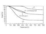
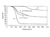
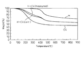
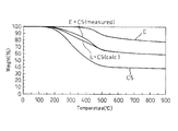
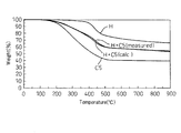
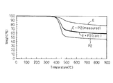
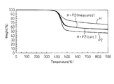
- the present inventors In order to grasp the interaction between the coal-based caking filler and coal, the present inventors mixed one kind of coal and one kind of caking filler at a weight ratio of 1: 1. 20 mg was heated to 900 ° C. at a rate of 3 ° C./min in a nitrogen atmosphere, and the change (decrease) in the sample weight over time was measured using a thermobalance. Since E coal or H charcoal was used as the coal, and any of the coal-based caking fillers C1 to C5 was used as the coal-based caking filler, ten types of samples were prepared.
- the present inventors measured weight reduction in the co-carbonization process of coal and caking filler using a mixture obtained by mixing coal and caking filler at a weight ratio of approximately 1: 1 as a sample.
- the measurement results are shown in FIGS.
- FIGS. 3 to 12 also show the measurement results of the coal simple substance and the caking filler simple substance.
- FIGS. 3 and 4 are the results using the coal-based caking filler C2.
- 5 and 6 show the results obtained using the coal-based caking filler C3.
- 7 and 8 show the results using the coal-based caking filler C1.
- 9 and 10 show the results obtained using the coal-based caking filler C4.
- 11 and 12 show the results using the coal-based caking filler C5.
- the measured weight loss (indicated as “measured”) in the co-carbonization process of the mixture of coal-based caking fillers C1 to C5 and coal is in the temperature range of 200 to 450 ° C. , Greater than the calculated weight loss (indicated by “calc.”).
- This calculated weight loss is a weighted average of the weight loss when testing coal alone and the weight loss when testing caking filler alone, and the interaction between coal and caking filler. (Interaction between different raw materials) is not considered. From the above, it can be seen that the coal-based caking filler has a strong interaction with coal in the temperature range from before softening and melting of coal to the initial stage of softening and melting.
- E charcoal having a high caking property (maximum fluidity (Max. Fluidity in Table 1) and total dilatation) has a large difference between the measured value and the calculated value compared with H charcoal. This means that coal with high caking property strongly interacts with caking filler.
- the present inventors have obtained the following knowledge from the above experimental results.
- the caking filler is (z1) a coal-based caking filler that interacts with coal in a temperature range below 400 ° C., and (z2) 400 It can be classified into petroleum-based caking fillers that do not interact with coal in a temperature range of less than 0 ° C but interact strongly with coal in a temperature range of 400 ° C or higher.
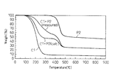
- the change over time (weight reduction) in the co-carbonization process of a caking filler (mixed caking filler), which is a mixture of a coal caking filler and a petroleum caking filler, is as follows. Measured.
- the measured weight loss (indicated by “measured”) of the mixture of coal-based caking filler and petroleum-based caking filler in the co-carbonization process is in the temperature range of 200 to 450 ° C. It can be seen that it is larger than the calculated weight loss (indicated by “calc.”).
- a caking filler (mixed caking filler), which is a mixture of a coal caking filler and a petroleum caking filler that does not interact with the coal before the softening and melting of the coal, softens and melts the coal. It means that it interacts strongly with coal in the temperature range from before to the early stage of softening and melting.
- the present inventors conducted an experiment for confirming the synergistic effect of the mixed caking filler of the coal caking filler and the petroleum caking filler as follows.
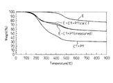
- E charcoal, coal-based caking filler C1, and petroleum caking filler P2 mixed at a weight ratio of 2: 1: 1; E charcoal, coal-based caking filler C1, and petroleum Similarly, a sample was prepared by mixing the system caking filler P1 at a weight ratio of 2: 1: 1. 20 mg of each sample was heated to 900 ° C. at a rate of 3 ° C./min in a nitrogen atmosphere, and the change over time (weight reduction) of the sample weight was measured using a thermobalance. The measurement results (weight reduction curves) are shown in FIGS. In addition, in FIG.19 and 20, the time-dependent change (weight reduction) of the weight reduction of a coal simple substance and the weight of a mixed caking filler simple substance is shown collectively.
- coal-based caking filler that interacts with coal below 400 ° C. and petroleum that does not interact with coal below 400 ° C. and interacts with coal above 400 ° C.
- co-carbonization is performed by mixing the system caking filler, in the process of co-carbonization, in the temperature range (200-400 ° C.) from before softening and melting of coal to the initial stage of softening and melting (coal and coal)
- a strong synergistic interaction between the two types of caking fillers) is developed, the expansion pressure during dry distillation is further suppressed, and the coke strength is significantly improved. This is the knowledge forming the basis of the present invention.
- the caking filler has been classified into coal-based and petroleum-based based on the source, but the index that specifically indicates the chemical phenomenon of interaction with coal is the co-carbonization of the caking filler. It is a change with time (decrease) in weight in the process.
- the temperature at which the weight reduction rate is maximized is defined as the maximum weight reduction temperature (Tmax (° C.)), and this Tmax (° C. ) To separate the caking filler. The reason for this is as follows.
- FIG. 21 shows the relationship between H / C (ratio of the number of hydrogen atoms to carbon) and Tmax (° C.) (maximum weight loss temperature) of coal-based caking filler and petroleum-based caking filler.
- the black squares are coal-based caking filler
- the white squares are petroleum caking filler. From FIG. 21, it can be seen that the caking filler is clearly divided with 400 ° C. as the boundary temperature.
- the H / C of the petroleum-based caking filler having a Tmax (° C.) of 400 ° C. or higher used in FIG. 21 is less than 2 and the coal-based caking filler having a Tmax (° C.) of less than 400 ° C. H / C was less than 1.
- a caking filler (first caking filler) having a maximum weight reduction temperature of 400 ° C. or higher and a caking filler (second caking filler) having a maximum weight reduction temperature of less than 400 ° C.
- the coking coal coexisting with the caking filler) is dry-distilled.
- the caking filler having a maximum weight reduction temperature of 400 ° C. or more and the caking filler having a maximum weight reduction temperature of less than 400 ° C. coexist in the raw coal.
- the coexistence form of the caking filler is not particularly limited.
- the caking filler having a maximum weight reduction temperature of 400 ° C. or more and the caking filler having a maximum weight reduction temperature of less than 400 ° C. may be sequentially mixed with the coal. Further, coal, a caking filler having a maximum weight reduction temperature of 400 ° C. or more, and a caking filler having a maximum weight reduction temperature of less than 400 ° C. may be mixed at the same time.
- a mixed caking filler is produced by mixing a caking filler having a maximum weight reduction temperature of 400 ° C. or more and a caking filler having a maximum weight reduction temperature of less than 400 ° C., and this mixed caking filler. May be mixed with coal.
- the present inventors conducted the following test in order to confirm the effect of the present invention (improvement of coke strength).
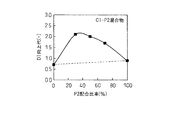
- the caking filler a (C1-P2 mixture) is a caking filler obtained by mixing a coal caking filler C1 and a petroleum caking filler P2.
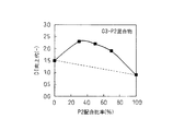
- the caking filler b (C3-P2 mixture) is a caking filler obtained by mixing the coal caking filler C3 and the petroleum caking filler P2.
- these caking fillers pulverized products in which -3 mm particles accounted for 100% were used.
- the measurement results are shown in FIGS.
- the vertical axis shows the difference (DI improvement margin) between the DI of coke produced by adding caking filler to coal and the DI of coke produced without adding caking filler to coal.
- 22 and 23 also show the DI improvement cost of coke strength when the coal-based caking fillers C1 and C3 and the petroleum-based caking filler P2 are blended individually.
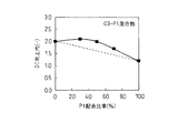
- the caking filler c (C3-P1 mixture) is a caking filler obtained by mixing a coal caking filler C3 and a petroleum caking filler P1.
- FIG. 24 shows the allowance for improving the coke strength DI when the coal-based caking filler C3 and the petroleum-based caking filler P1 are blended independently.
- FIG. 24 shows that coke strength is remarkably improved when the above-mentioned caking filler is allowed to coexist with 3% of coking coal in dry distillation.
- a caking filler (first caking filler) having a maximum weight reduction temperature of 400 ° C. or higher and a maximum weight reduction temperature of 400 ° C.
- the coke raw material in which the caking filler (second caking filler) that is less than this is contained in the raw coal is dry-distilled.
- the weight reduction rate obtained by first-order differentiation of the weight reduction (weight reduction curve) when the sample (caking filler) is heated to 900 ° C. at 3 ° C./min.
- the temperature at which the weight reduction speed in the speed curve is maximized is defined as the maximum weight reduction temperature.
- the caking filler having a maximum weight reduction temperature of 400 ° C. or more and the caking filler having a maximum weight reduction temperature of less than 400 ° C. basically have different characteristics.
- the difference ⁇ T in the maximum weight reduction temperature of these caking fillers is preferably 50 ° C. or higher.
- the upper limit of the maximum weight reduction temperature difference ⁇ T is not particularly limited, but may be, for example, 300 ° C.
- Tpmax the maximum weight reduction temperature of the caking filler whose maximum weight reduction temperature is 400 ° C. or higher
- Tcmax the maximum weight reduction temperature of the caking filler whose maximum weight reduction temperature is less than 400 ° C.
- a plurality of (plural types) caking fillers having a maximum weight reduction temperature of 400 ° C. or more may be blended in the raw coal. Moreover, you may mix
- the upper limit of the total amount of the caking filler is not particularly limited from the viewpoint of improving the coke strength. However, at present, if the addition rate of the caking filler is too high, (a) an increase in the amount of carbon adhering to the coking chamber wall of the coke oven, (b) an operation such as a decrease in the coke yield, and production. Challenges may arise. Therefore, the upper limit of the total amount of the caking filler is preferably 10%.
- the abundance of the caking filler having a maximum weight reduction temperature of 400 ° C. or more and the abundance of the caking filler having a maximum weight reduction temperature of less than 400 ° C. are in a mass ratio of 1: 9 to 9: 1. Is preferred. That is, it is preferable that the ratio of the caking filler having a maximum weight reduction temperature of 400 ° C. or more to the total amount of the caking filler is 0.1 to 0.9 in terms of mass ratio. Further, in order to sufficiently exhibit the caking property of the caking filler, the H / C of the caking filler having a maximum weight reduction temperature of 400 ° C. or higher is preferably more than 0 and less than 2, 400 ° C. It is preferable that H / C of less than caking filler is less than 1 and less than 1.
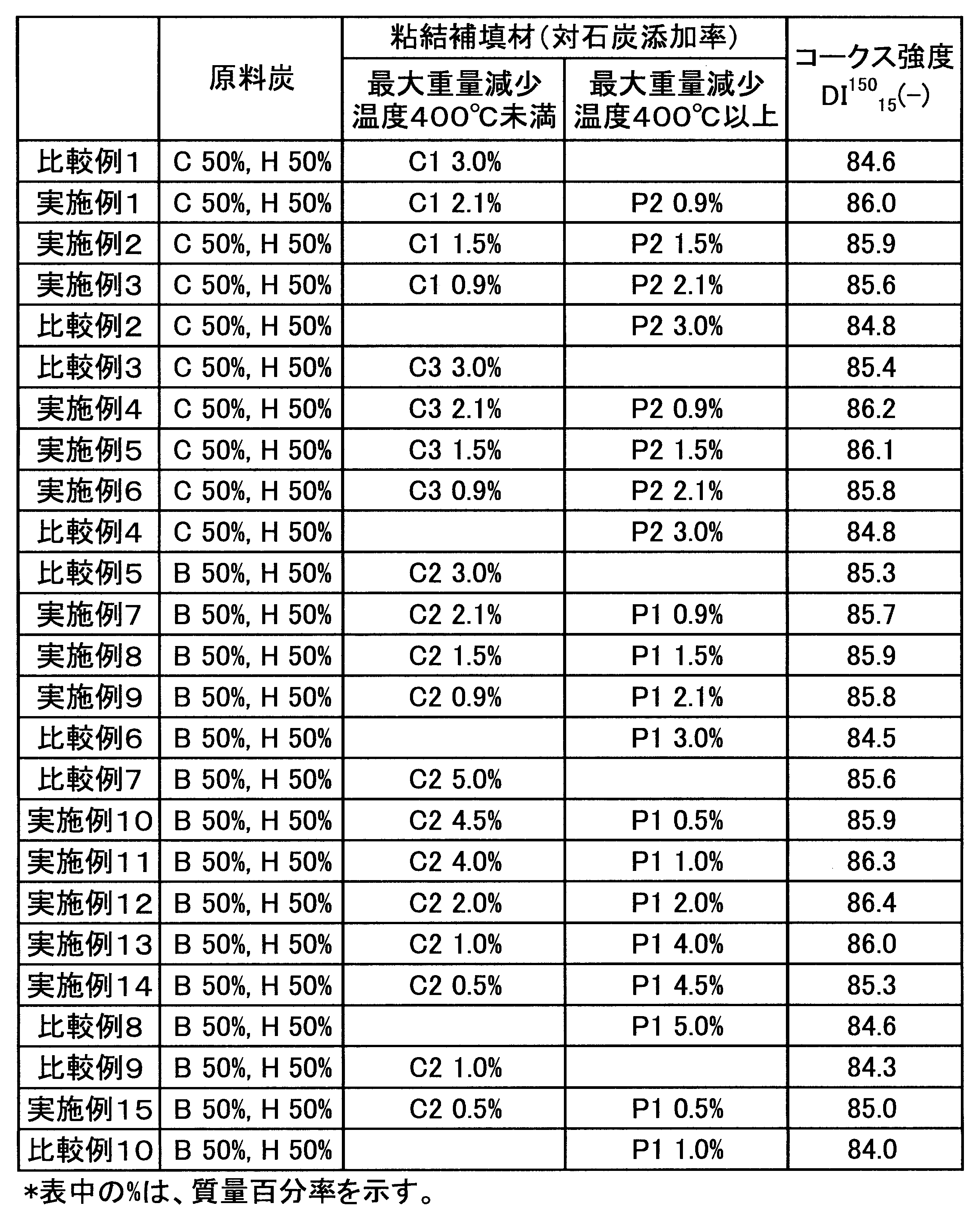
- Example 3 Coke raw materials (coking coal and caking filler) having the conditions shown in Table 3 are heated in a furnace with a furnace temperature of 1250 ° C. under conditions of a dry distillation time of 18.5 hours to produce coke, and coke according to JIS K 2151 Intensity DI 150 15 ( ⁇ ) was measured. The measurement results are also shown in Table 3. Coke strength DI 0.99 15 Example (-) is coke strength DI 0.99 15 Comparative Example (-) in comparison, comparison of significantly higher it is seen (Comparative Examples 1 and 2 Examples 1-3 and Comparative Examples Comparison between Examples 3 and 4 and Examples 4 to 6, Comparison between Examples 5 and 6 and Examples 7 to 9, Comparison between Examples 7 and 8 and Examples 10 to 14, Comparison with Examples 8 and 10 Comparison with Example 15).
- the present invention As described above, according to the present invention, a high-strength coke having a coke strength equal to or higher than a coke strength obtained by mixing a simple caking filler and raw coal can be produced. Therefore, the present invention has high applicability in the coke manufacturing industry.
Landscapes
- Chemical & Material Sciences (AREA)
- Engineering & Computer Science (AREA)
- Materials Engineering (AREA)
- Oil, Petroleum & Natural Gas (AREA)
- Organic Chemistry (AREA)
- Coke Industry (AREA)
- Carbon And Carbon Compounds (AREA)
Abstract
Description
本願は、2010年2月25日に、日本に出願された特願2010-40650号に基づき優先権を主張し、その内容をここに援用する。
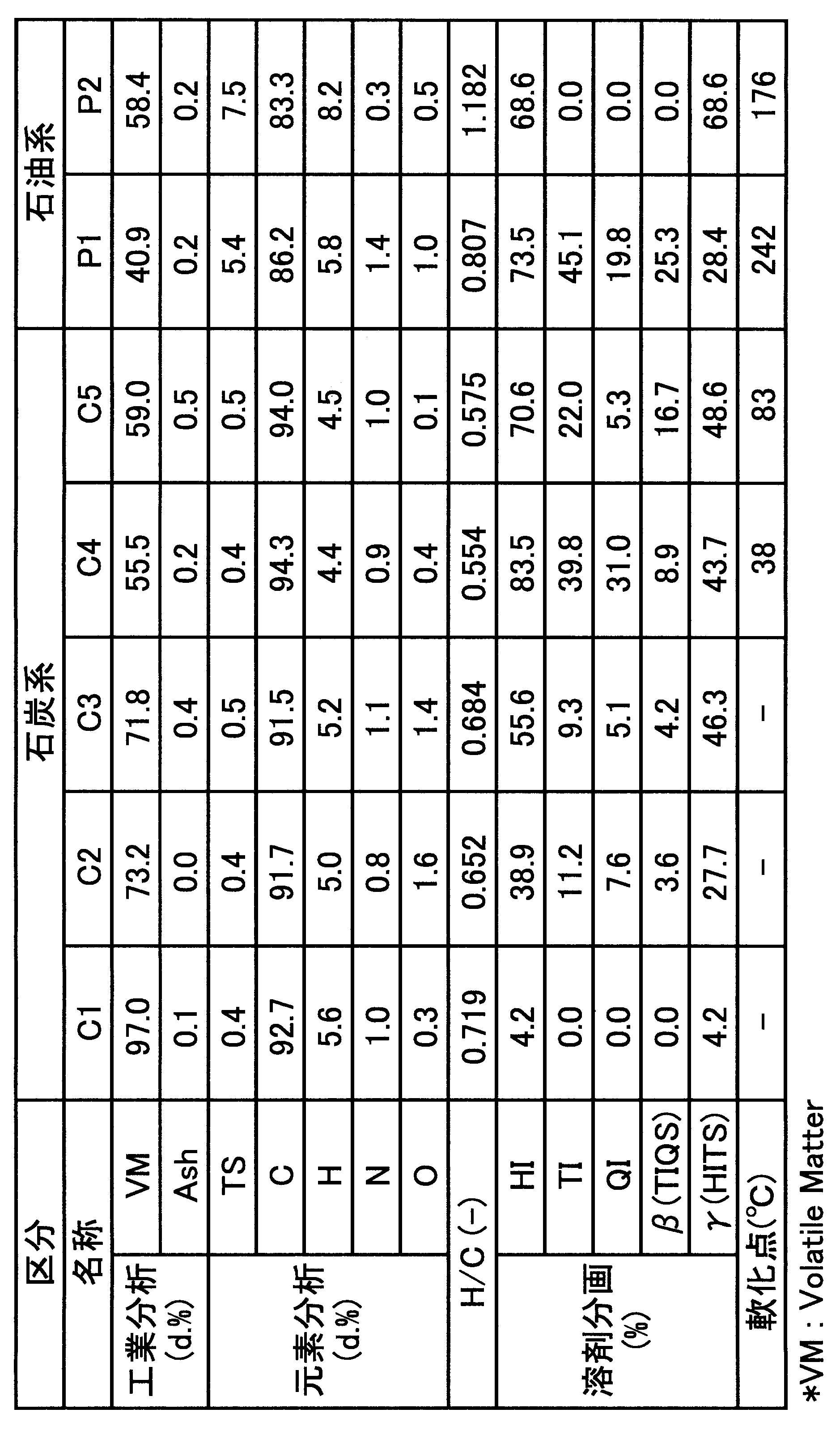
(1)表1に、実験に用いた石炭の性状を示す。表2に、実験に用いた粘結補填材の性状を示す。

(i)石炭系粘結補填材が400~500℃(石炭の軟化溶融温度範囲)で熱分解して極微量成分を放出し、この極微量成分が石炭の粘結性向上に寄与する。
(ii)石炭系粘結補填材と石炭とが加熱される過程(共炭化過程)で、石炭系粘結補填材と石炭との間で相互作用が生じ、その結果、石炭が改質されて粘結性が向上する。
以上の実験結果によれば、(i)のメカニズムよりもむしろ(ii)のメカニズムにより粘結性が向上すると考えられる。
本発明者らは、次に、石油系粘結補填材と石炭との相互作用を把握するため、石炭(E炭又はH炭)と石油系粘結補填材P2とを、重量比1:1で混合した試料20mgを、窒素雰囲気中で、900℃まで3℃/minで昇温し、熱天秤を用いて重量の経時変化を測定した。測定結果(重量減少曲線)を、図13及び14に示す。なお、図13及び14には、石炭単味及び粘結補填材単味についての測定結果も併せて示している。
C炭50%とH炭50%(表1、参照)とからなる、3mm以下(-3mm)の粒子が85%を占める原料炭に、次の粘結補填材(粘結補填材aまたはb)を3%共存させ、嵩密度0.85で乾留してコークスを製造し、コークス強度DI150 15(-)(以下では、DIと記載することもある)を測定した。
C炭50%とH炭50%(表1、参照)とからなる、-3mmの粒子が85%を占める原料炭に、次の粘結補填材cを3%共存させ、嵩密度0.85で乾留してコークスを製造し、コークス強度DI150 15(-)を測定した。
粘結補填材c(C3-P1混合物)は、石炭系粘結補填材C3と石油系粘結補填材P1とを混合した粘結補填材である。
次に、本発明の好ましい実施形態について、説明する。
ΔT=Tpmax-Tcmax ・・・(1)
また、粘結補填材の粘結性を十分に発揮するためには、最大重量減少温度が400℃以上の粘結補填材のH/Cが0超かつ2未満であることが好ましく、400℃未満の粘結補填材のH/Cが0超かつ1未満であることが好ましい。
表3に示す条件のコークス原料(原料炭及び粘結補填材)を、炉温1250℃の炉内で乾留時間18.5時間の条件で加熱して、コークスを製造し、JIS K 2151によりコークス強度DI150 15(-)を測定した。測定結果を、表3に併せて示す。実施例のコークス強度DI150 15(-)は、比較例のコークス強度DI150 15(-)に比べ、著しく高いことが解る(比較例1、2と実施例1~3との比較、比較例3、4と実施例4~6との比較、比較例5、6と実施例7~9との比較、比較例7、8と実施例10~14との比較、比較例8、10と実施例15との比較)。
Claims (8)
- 900℃まで3℃/minで昇温した時の重量減少を時間で一次微分して得られる重量減少速度が最大になる温度を最大重量減少温度と定義した場合に、最大重量減少温度が400℃以上である第一の粘結補填材と、最大重量減少温度が400℃未満である第二の粘結補填材とを原料炭中に含有させたコークス原料を乾留することを特徴とする高強度コークスの製造方法。
- 前記第一の粘結補填材の最大重量減少温度と前記第二の粘結補填材の最大重量減少温度との差が、50℃以上であることを特徴とする請求項1に記載の高強度コークスの製造方法。
- 前記第一の粘結補填材と前記第二の粘結補填材との合計量が、0.2質量%以上であることを特徴とする請求項1又は2に記載の高強度コークスの製造方法。
- 前記第一の粘結補填材と前記第二の粘結補填材との合計量に対する前記第一の粘結補填材の比率が、質量比で、0.1~0.9であることを特徴とする請求項1又は2に記載の高強度コークスの製造方法。
- 前記第一の粘結補填材を、複数、原料炭中に含有させることを特徴とする請求項1又は2に記載の高強度コークスの製造方法。
- 前記第二の粘結補填材を、複数、原料炭中に含有させることを特徴とする請求項1又は2に記載の高強度コークスの製造方法。
- 前記第一の粘結補填材が石油系粘結補填材であることを特徴とする請求項1又は2に記載の高強度コークスの製造方法。
- 前記第二の粘結補填材が石炭系粘結補填材であることを特徴とする請求項1又は2に記載の高強度コークスの製造方法。
Priority Applications (4)
| Application Number | Priority Date | Filing Date | Title |
|---|---|---|---|
| KR1020127021922A KR101430850B1 (ko) | 2010-02-25 | 2011-02-24 | 고강도 코크스의 제조 방법 |
| BR112012021193A BR112012021193B8 (pt) | 2010-02-25 | 2011-02-24 | Método de produção de coque de alta resistência |
| JP2011527089A JP4902030B1 (ja) | 2010-02-25 | 2011-02-24 | 高強度コークスの製造方法 |
| CN201180010698.XA CN102869751B (zh) | 2010-02-25 | 2011-02-24 | 高强度焦炭的制造方法 |
Applications Claiming Priority (2)
| Application Number | Priority Date | Filing Date | Title |
|---|---|---|---|
| JP2010-040650 | 2010-02-25 | ||
| JP2010040650 | 2010-02-25 |
Publications (1)
| Publication Number | Publication Date |
|---|---|
| WO2011105480A1 true WO2011105480A1 (ja) | 2011-09-01 |
Family
ID=44506880
Family Applications (1)
| Application Number | Title | Priority Date | Filing Date |
|---|---|---|---|
| PCT/JP2011/054122 Ceased WO2011105480A1 (ja) | 2010-02-25 | 2011-02-24 | 高強度コークスの製造方法 |
Country Status (6)
| Country | Link |
|---|---|
| JP (1) | JP4902030B1 (ja) |
| KR (1) | KR101430850B1 (ja) |
| CN (1) | CN102869751B (ja) |
| BR (1) | BR112012021193B8 (ja) |
| TW (1) | TWI438268B (ja) |
| WO (1) | WO2011105480A1 (ja) |
Cited By (1)
| Publication number | Priority date | Publication date | Assignee | Title |
|---|---|---|---|---|
| WO2017073444A1 (ja) * | 2015-10-27 | 2017-05-04 | 株式会社神戸製鋼所 | コークス製造用組成物、成型炭、高炉用コークス、及び高炉用コークスの製造方法、並びに製鉄原料用組成物、製鉄原料用成型物、高炉用製鉄原料、及び高炉用製鉄原料の製造方法 |
Citations (8)
| Publication number | Priority date | Publication date | Assignee | Title |
|---|---|---|---|---|
| JPS51147503A (en) * | 1975-06-12 | 1976-12-17 | Sumikin Coke Co Ltd | Caking agent for briquette coal |
| JPS523402B2 (ja) * | 1972-04-19 | 1977-01-27 | ||
| JPS5212201B2 (ja) * | 1971-06-01 | 1977-04-05 | ||
| JPS5316004A (en) * | 1976-07-30 | 1978-02-14 | Nittetsu Kagaku Kogyo Kk | Method of producing binder for molded coal by partially using hard pitch and heavy oil* etc* as material |
| JPS5441601B2 (ja) * | 1975-11-14 | 1979-12-10 | ||
| JPS56118486A (en) * | 1980-02-25 | 1981-09-17 | Kashima Sekiyu Kk | Preparation of metallurgic coke |
| JPS5720359B2 (ja) * | 1975-04-17 | 1982-04-28 | ||
| WO2010116722A1 (ja) * | 2009-04-09 | 2010-10-14 | 新日本製鐵株式会社 | 高炉用コークスの製造方法 |
Family Cites Families (1)
| Publication number | Priority date | Publication date | Assignee | Title |
|---|---|---|---|---|
| JP4102426B2 (ja) * | 2005-05-13 | 2008-06-18 | 新日本製鐵株式会社 | 高炉用コークスの製造方法 |
-
2011
- 2011-02-24 BR BR112012021193A patent/BR112012021193B8/pt active IP Right Grant
- 2011-02-24 CN CN201180010698.XA patent/CN102869751B/zh active Active
- 2011-02-24 WO PCT/JP2011/054122 patent/WO2011105480A1/ja not_active Ceased
- 2011-02-24 KR KR1020127021922A patent/KR101430850B1/ko active Active
- 2011-02-24 JP JP2011527089A patent/JP4902030B1/ja active Active
- 2011-02-25 TW TW100106428A patent/TWI438268B/zh active
Patent Citations (8)
| Publication number | Priority date | Publication date | Assignee | Title |
|---|---|---|---|---|
| JPS5212201B2 (ja) * | 1971-06-01 | 1977-04-05 | ||
| JPS523402B2 (ja) * | 1972-04-19 | 1977-01-27 | ||
| JPS5720359B2 (ja) * | 1975-04-17 | 1982-04-28 | ||
| JPS51147503A (en) * | 1975-06-12 | 1976-12-17 | Sumikin Coke Co Ltd | Caking agent for briquette coal |
| JPS5441601B2 (ja) * | 1975-11-14 | 1979-12-10 | ||
| JPS5316004A (en) * | 1976-07-30 | 1978-02-14 | Nittetsu Kagaku Kogyo Kk | Method of producing binder for molded coal by partially using hard pitch and heavy oil* etc* as material |
| JPS56118486A (en) * | 1980-02-25 | 1981-09-17 | Kashima Sekiyu Kk | Preparation of metallurgic coke |
| WO2010116722A1 (ja) * | 2009-04-09 | 2010-10-14 | 新日本製鐵株式会社 | 高炉用コークスの製造方法 |
Cited By (1)
| Publication number | Priority date | Publication date | Assignee | Title |
|---|---|---|---|---|
| WO2017073444A1 (ja) * | 2015-10-27 | 2017-05-04 | 株式会社神戸製鋼所 | コークス製造用組成物、成型炭、高炉用コークス、及び高炉用コークスの製造方法、並びに製鉄原料用組成物、製鉄原料用成型物、高炉用製鉄原料、及び高炉用製鉄原料の製造方法 |
Also Published As
| Publication number | Publication date |
|---|---|
| KR101430850B1 (ko) | 2014-08-18 |
| CN102869751B (zh) | 2014-05-07 |
| JPWO2011105480A1 (ja) | 2013-06-20 |
| BR112012021193B1 (pt) | 2018-10-09 |
| CN102869751A (zh) | 2013-01-09 |
| TWI438268B (zh) | 2014-05-21 |
| KR20120123458A (ko) | 2012-11-08 |
| JP4902030B1 (ja) | 2012-03-21 |
| BR112012021193B8 (pt) | 2022-10-04 |
| TW201139645A (en) | 2011-11-16 |
| BR112012021193A2 (pt) | 2016-05-17 |
Similar Documents
| Publication | Publication Date | Title |
|---|---|---|
| WO2006121213B1 (ja) | 高炉用コークスの製造方法 | |
| JP5949706B2 (ja) | コークスの製造方法、コークス、改質石炭、改質配合炭および石炭もしくは配合炭の改質方法 | |
| JP2010209310A (ja) | 配合炭の比容積の測定方法、コークス表面破壊強度の推定方法及び石炭配合方法 | |
| JP6036411B2 (ja) | 石炭の改質方法及びコークスの製造方法 | |
| RU2627425C1 (ru) | Шихта для получения металлургического кокса | |
| JP4902030B1 (ja) | 高強度コークスの製造方法 | |
| JP5444709B2 (ja) | 高炉用コークスの製造方法 | |
| KR101767800B1 (ko) | 야금용 코크스의 제조 방법 | |
| WO2013118821A1 (ja) | コークス製造用成型炭の製造方法及びコークスの製造方法 | |
| JP6241336B2 (ja) | 高炉用コークスの製造方法 | |
| CN112899052B (zh) | 阻氢剂及配入大比例高挥发性烟煤生产焦炭的方法 | |
| RU2418837C1 (ru) | Добавка к шихтам для коксования | |
| JP6227482B2 (ja) | 高炉用コークスの製造方法及び高炉用コークス | |
| JP5163247B2 (ja) | コークスの製造方法 | |
| JP6464912B2 (ja) | コークスの製造方法 | |
| JP6266409B2 (ja) | 石炭混合材 | |
| JPH04309594A (ja) | 高炉用コークスの製造方法 | |
| WO2022108484A1 (ru) | Состав шихты для получения металлургического кокса | |
| JP2007246593A (ja) | コークスの製造方法 | |
| KR101503443B1 (ko) | 코크스용 조성물 및 코크스 제조 방법 | |
| JP5749952B2 (ja) | 改質炭の石炭化度の推定及び評価方法 | |
| JP2019002011A (ja) | コークスの製造方法 | |
| JP2001323281A (ja) | コークス製造方法 | |
| JP2007016186A (ja) | コークスの製造方法 | |
| JP2021042378A (ja) | 石炭のイナートファクター係数推定方法及びコークス表面破壊強度の推定方法 |
Legal Events
| Date | Code | Title | Description |
|---|---|---|---|
| WWE | Wipo information: entry into national phase |
Ref document number: 201180010698.X Country of ref document: CN |
|
| WWE | Wipo information: entry into national phase |
Ref document number: 2011527089 Country of ref document: JP |
|
| 121 | Ep: the epo has been informed by wipo that ep was designated in this application |
Ref document number: 11747440 Country of ref document: EP Kind code of ref document: A1 |
|
| DPE1 | Request for preliminary examination filed after expiration of 19th month from priority date (pct application filed from 20040101) | ||
| WWE | Wipo information: entry into national phase |
Ref document number: 7243/DELNP/2012 Country of ref document: IN |
|
| ENP | Entry into the national phase |
Ref document number: 20127021922 Country of ref document: KR Kind code of ref document: A |
|
| NENP | Non-entry into the national phase |
Ref country code: DE |
|
| 122 | Ep: pct application non-entry in european phase |
Ref document number: 11747440 Country of ref document: EP Kind code of ref document: A1 |
|
| REG | Reference to national code |
Ref country code: BR Ref legal event code: B01A Ref document number: 112012021193 Country of ref document: BR |
|
| ENP | Entry into the national phase |
Ref document number: 112012021193 Country of ref document: BR Kind code of ref document: A2 Effective date: 20120823 |