WO2011105404A1 - 液封防振装置 - Google Patents
液封防振装置 Download PDFInfo
- Publication number
- WO2011105404A1 WO2011105404A1 PCT/JP2011/053921 JP2011053921W WO2011105404A1 WO 2011105404 A1 WO2011105404 A1 WO 2011105404A1 JP 2011053921 W JP2011053921 W JP 2011053921W WO 2011105404 A1 WO2011105404 A1 WO 2011105404A1
- Authority
- WO
- WIPO (PCT)
- Prior art keywords
- elastic body
- outer peripheral
- relief valve
- relief
- frame member
- Prior art date
- Legal status (The legal status is an assumption and is not a legal conclusion. Google has not performed a legal analysis and makes no representation as to the accuracy of the status listed.)
- Ceased
Links
Images











Classifications
-
- F—MECHANICAL ENGINEERING; LIGHTING; HEATING; WEAPONS; BLASTING
- F16—ENGINEERING ELEMENTS AND UNITS; GENERAL MEASURES FOR PRODUCING AND MAINTAINING EFFECTIVE FUNCTIONING OF MACHINES OR INSTALLATIONS; THERMAL INSULATION IN GENERAL
- F16F—SPRINGS; SHOCK-ABSORBERS; MEANS FOR DAMPING VIBRATION
- F16F13/00—Units comprising springs of the non-fluid type as well as vibration-dampers, shock-absorbers, or fluid springs
- F16F13/04—Units comprising springs of the non-fluid type as well as vibration-dampers, shock-absorbers, or fluid springs comprising both a plastics spring and a damper, e.g. a friction damper
- F16F13/06—Units comprising springs of the non-fluid type as well as vibration-dampers, shock-absorbers, or fluid springs comprising both a plastics spring and a damper, e.g. a friction damper the damper being a fluid damper, e.g. the plastics spring not forming a part of the wall of the fluid chamber of the damper
- F16F13/08—Units comprising springs of the non-fluid type as well as vibration-dampers, shock-absorbers, or fluid springs comprising both a plastics spring and a damper, e.g. a friction damper the damper being a fluid damper, e.g. the plastics spring not forming a part of the wall of the fluid chamber of the damper the plastics spring forming at least a part of the wall of the fluid chamber of the damper
- F16F13/10—Units comprising springs of the non-fluid type as well as vibration-dampers, shock-absorbers, or fluid springs comprising both a plastics spring and a damper, e.g. a friction damper the damper being a fluid damper, e.g. the plastics spring not forming a part of the wall of the fluid chamber of the damper the plastics spring forming at least a part of the wall of the fluid chamber of the damper the wall being at least in part formed by a flexible membrane or the like
- F16F13/105—Units comprising springs of the non-fluid type as well as vibration-dampers, shock-absorbers, or fluid springs comprising both a plastics spring and a damper, e.g. a friction damper the damper being a fluid damper, e.g. the plastics spring not forming a part of the wall of the fluid chamber of the damper the plastics spring forming at least a part of the wall of the fluid chamber of the damper the wall being at least in part formed by a flexible membrane or the like characterised by features of partitions between two working chambers
- F16F13/106—Design of constituent elastomeric parts, e.g. decoupling valve elements, or of immediate abutments therefor, e.g. cages
Definitions
- the present invention relates to a liquid seal vibration isolator used for a power train mount of an automobile, and more particularly to an apparatus capable of effectively reducing abnormal noise generated by a cavitation phenomenon and realizing high attenuation.
- the partition member is composed of a frame member such as metal and an elastic body fitted and supported by the frame member, and the central portion of the elastic body is formed as a thin circular movable film to absorb the fluid pressure fluctuation in the main liquid chamber, and
- the outer peripheral portion of the elastic body is formed thick and a relief valve is integrally formed on the outer peripheral portion. In this case, when the elastic body receives a force in the rotational direction (in the direction indicated by the arrow A in FIG. 10) by the hydraulic fluid swirling into the orifice passage and the elastic body rotates with respect to the frame member, the relief valve is moved to the relief passage.
- Opening and closing may be inaccurate, and the prevention of the occurrence of cavitation may be uncertain.
- a thick protrusion is provided on the outer periphery of the elastic body, and this is fixed to the frame member to prevent rotation.
- the relief valves are provided at equal intervals in the circumferential direction, and the respective circumferential lengths (circumferential lengths) are formed at about 60 ° in terms of the opening angle from the center and about 1/6 of the entire circumference. ing.
- each relief valve is provided at 90 ° intervals in the circumferential direction of the elastic body, and protrusions for preventing rotation are provided between adjacent relief valves.
- the stopping protrusion is only provided partially protruding from the outer periphery, and the shape cannot be maintained against excessive force, may deform at the time of large input, and there is a case where reliable rotation prevention cannot be performed there were.
- the relief valve ensures a large flow rate of hydraulic fluid during relief. For this reason, it is necessary to make it as large as possible.
- the portion that forms both ends of the relief valve in the length direction is fixed to the frame member. However, this portion is pulled toward the intermediate portion in the longitudinal direction of the relief valve and elastically deformed. Due to the deformation at this time, a gap is formed between the frame member and the leakage force may decrease due to liquid leakage. It was. Furthermore, when the relief valve is elastically deformed at the time of a large input, it is conceivable that a part of the relief valve is locally deformed to reduce the sealing performance, and the damping force is lowered by liquid leakage from this.
- the present invention has an object to reliably prevent the occurrence of the cavitation phenomenon by accurately positioning the partitioning member using the elastic body so that the elastic body can be reliably prevented from rotating. It is also aimed to be able to realize attenuation.
- the relief valve is integrally formed on the outer peripheral thick portion of the elastic body as in the above-described conventional example, the arrangement and formation of the relief valve are facilitated.
- the relief valve is provided in an arc shape in the circumferential direction of the outer peripheral thick portion, both end portions in the length direction are continuous with the thick portion of the elastic body and have a high bending rigidity, resulting in resistance during opening and closing.
- four relief valves are provided, the number of resistance parts during opening and closing is increased. If the resistance can be reduced and the valve can be opened and closed more smoothly, when the cavitation phenomenon needs to be suppressed, the relief valve opens smoothly and the hydraulic fluid is quickly transferred from the sub liquid chamber to the main liquid chamber.
- the pressure receiving area facing the main liquid chamber of the movable membrane is increased or the film thickness is increased. It is possible to make it thinner.
- the area of the movable membrane should be relatively narrow due to the necessity of forming a relief valve on the outer periphery in accordance with the basic requirement to make the whole vibration isolator compact, and the area of the movable membrane can be freely expanded. I can't.
- the film thickness of the movable film also has a predetermined limit, and reducing it indefinitely causes a significant decrease in damping force, so there is a limit.
- the partition member that divides the liquid chamber into the main liquid chamber and the sub liquid chamber and that is provided with the orifice passage that communicates them is provided with the elastic body and the elastic member.
- a frame member that fits and supports the body, a thin movable film at the center of the elastic body, and a thick outer peripheral part around the movable film, and a relief valve is integrally formed on the thick outer peripheral part.
- the relief valve is only a pair arranged to face each other across the center of the elastic body, While making the outer periphery of the portion between the pair of relief valves out of the thick outer peripheral portion into a non-circular anti-rotation portion,
- the frame member is provided with a fitting portion corresponding to the detent portion, The elastic body was fitted to the frame member, and the detent portion and the fitting portion were fitted.
- a part of the movable film enters into the thick outer peripheral portion located between the pair of relief valves, and the movable film is formed into a non-circular shape.
- the said rotation stop part was made into the 2 surface width shape formed in the linear form which parallels the opposing position of an outer peripheral part with respect to the thick outer peripheral part of the said elastic body.
- an intermediate support in which an arc-shaped relief hole is provided at a position corresponding to the relief valve of the frame member, and the relief valve is supported at an intermediate portion in the longitudinal direction of the relief hole. Part was formed.
- At least a part of the anti-rotation portion and the fitting portion for fitting the anti-rotation portion is tapered.
- a corner portion that is a portion adjacent to the lengthwise end portion of the relief valve in the elastic body, and a corner provided on the frame member side that fits the corner portion.
- Each part was made into the said taper shape.
- an intermediate support portion that supports the sub liquid chamber side portion of the relief valve is formed on the frame member.
- the frame member is formed with a concave portion constituting the orifice passage in a state where the outer side is opened, and the outer side of the orifice passage is closed by closing the concave portion.
- the member which closes a part was made into the member which covers each outer side of the said liquid chamber and a partition member.
- the relief valve has an arc shape along one assumed circle, and has a length of about 1/3 of the circumference of the assumed circle in the circumferential direction of the elastic body. It is formed.
- only one pair of relief valves arranged in a long arc shape in the circumferential direction is provided on the thick outer peripheral portion of the elastic body so as to face each other.
- the number of lengthwise ends that are difficult to open and close can be halved, and can be opened and closed smoothly.
- a frame member provided with a fitting portion corresponding to the anti-rotation portion by forming the entire portion between the pair of relief valves in the thick outer peripheral portion of the elastic body into a non-circular shape in plan view as a non-rotation portion.
- the elastic body By fitting the elastic body, the entire thick outer peripheral part between the pair of relief valves is used as the support fixing part of the relief valve, so that the support fixing part of the relief valve can have high support rigidity. For this reason, the elastic body can be accurately positioned with respect to the frame member and the relief passage can be kept constant, so that a predetermined relief flow rate can be secured when the cavitation phenomenon occurs at the time of large input, and the cavitation phenomenon Can be reliably prevented. In addition, it is possible to make the apparatus compact without enlarging the outer diameter of the entire apparatus, and it is possible to maintain predetermined damping and durability because the movable film does not need to be unnecessarily thin for the purpose of reducing the dynamic spring.
- a part of the movable film enters the thick outer peripheral portion located between the pair of relief valves, and the movable film is made noncircular.
- the pressure receiving area can be expanded as a large circular structure, and the relief valve is provided on the outer peripheral portion, the movable film spring can be lowered to realize a low dynamic spring. Therefore, the relief valve can be opened and closed smoothly and a low dynamic spring can be realized at the same time.
- the anti-rotation portion is a two-sided width shape formed in a straight line parallel to the opposing position of the outer peripheral portion with respect to the thick outer peripheral portion of the elastic body. A reliable detent structure can be obtained.
- the longitudinal direction intermediate part of a relief valve is large by supporting the longitudinal direction intermediate part of a relief valve by an intermediate support part. Prevents deformation. For this reason, the large relief valve can be substantially used, and the distance between the pair of relief valves on the thick outer peripheral portion can be sufficiently increased.
- the taper is adjusted by fitting the anti-rotation portion to the fitting portion.
- the partition member can be easily assembled.
- the sealing performance of the taper matching portion can be improved, so that even if a large force is applied to the outer periphery of the elastic body during a large input, a high liquid-tight state is maintained between the elastic outer periphery of the taper matching portion and the frame member. Since the liquid leakage from this part can be prevented and the decrease in damping force can be prevented.
- the elastic body is attached to the frame member by taper matching. Can be positioned accurately. As a result, the relief passage can be accurately formed, and the occurrence of the cavitation phenomenon can be reliably prevented.
- a high sealing performance at the taper matching portion is obtained, liquid leakage can be prevented by the taper matching portion even in the corner portion in the vicinity of the relief valve that is susceptible to elastic deformation.
- the frame member is formed with the intermediate support portion for supporting the auxiliary liquid chamber side portion of the relief valve, the excessive deformation of the relief valve at the time of a large input is prevented to reduce the damping force. Decline can be prevented.
- the reduction of the damping force can be prevented in the same manner, so that one relief valve can be lengthened and the number of relief valves in the whole can be reduced to only one pair.
- the frame member is not provided with a member that closes the outer side of the concave portion that constitutes the orifice passage, and this is a member that covers each outer side of the liquid chamber and the partition member.
- the orifice passage 108 can be arranged closer to the outer peripheral side by the amount of the member that closes the outer side of the recessed portion constituting the omitted orifice passage. For this reason, a relief valve can be enlarged more and the part of the thick outer peripheral part which forms an enlarged part can be ensured large enough.
- the relief valve is lengthened to about 1/3 of the assumed circle along the arc, the hydraulic fluid flow rate at the time of relief is increased to efficiently generate the cavitation phenomenon. Can be suppressed.
- Sectional drawing of the liquid seal vibration isolator which concerns on 1st embodiment of this invention Plan view of frame member 3-3 sectional view of FIG. Top view of elastic body 5-5 sectional view of FIG. 6-6 sectional view of FIG. 7-7 sectional view of FIG. Disassembled perspective view of partition member Cross section of partition member Plan view of a state in which an elastic body is fitted to the frame member 11-11 sectional view of FIG. Sectional drawing explaining the effect
- omitted a part of frame member which concerns on 2nd Example 15 is a sectional view taken along line 16-16 in FIG.
- liquid seal vibration isolator configured as an automobile engine mount, which is an example of a powertrain mount, will be described below with reference to the drawings.
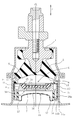
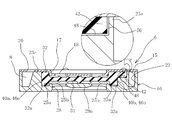
- FIG. 1 is a cross section taken along the central axis CL of the liquid seal vibration isolator according to the first embodiment of the present invention.
- This engine mount connects between a first mounting member 1 mounted on an engine (not shown) as a vibration source and a second mounting member 2 mounted on a vehicle body (same as above) on the vibration receiving side.
- an insulator 3 is composed of a known vibration-proofing elastic member such as rubber, and is an elastic body that is a vibration-proof main member against vibration.
- the vibration input to the first mounting member 1 from the main vibration input direction Z is first the insulator. 3 is absorbed by elastic deformation.
- the input direction Z of the main vibration is parallel to the center line CL shown in the figure.
- a view along the Z direction from above is referred to as a plan view (plan view).
- the insulator 3 has a substantially frustoconical cross section and is provided with a dome-shaped portion 4 on the inner side.
- the dome-shaped portion 4 forms a recess opened downward in FIG. 1, and an incompressible hydraulic fluid is sealed in the recess.
- the main liquid chamber 5 is formed.
- the main liquid chamber 5 is partitioned from the secondary liquid chamber 7 by the partition member 6, and is communicated with the secondary liquid chamber 7 by separating the partition member 6 by the orifice passage 8.
- the auxiliary liquid chamber 7 is formed between the diaphragm 10 and the partition member 6, and the diaphragm 10 is a part of the wall portion.
- the partition member 6 has a movable film portion (described later) that absorbs fluid pressure fluctuations in the orifice passage 8 and the main liquid chamber 5 and a relief for relieving the hydraulic fluid from the sub liquid chamber 7 side to the main liquid chamber 5 side when a large input is applied.
- a valve (same as above) is provided.
- the orifice passage 8 is a damped orifice set so as to resonate with a low-frequency vibration such as a shake vibration of about 10 to 11 Hz.
- the second mounting member 2 is provided with a cylindrical outer tube fitting 11, and the outer tube fitting 11 is fitted to the holder 2a as necessary, or attached to the vehicle body via a bracket.
- the outer cylinder fitting 11 forms part of the second mounting member 2.
- An extension portion 12 of the insulator 3 is integrated inside the outer tube fitting 11, and the extension portion 12 extends downward as much as the height of the partition member 6 and integrally covers the inner surface of the outer tube fitting 11. .
- a slight gap (not shown) is formed between the extension portion 12 and the outer peripheral portion of the partition member 6.
- the portion facing the main liquid chamber 5 at the upper part of the extension portion 12 forms a thick-walled step 14 where the outer peripheral end of the partition member 6 is positioned.
- the diaphragm 10 includes a thin portion 36 that is a main body portion and a thick portion 37 that is integrally formed on the outer periphery thereof, and a fixing ring 38 is inserted into the thick portion 37 to be integrated. From the outer peripheral surface of the fixing ring 38, a seal portion 38 a that is a part of the thick portion 37 protrudes radially outward. The fixing ring 38 is inserted into the outer cylindrical metal member 11 through the seal portion 38a and fixed by caulking.
- the partition member 6 is inserted from the upper side of the outer cylinder fitting 11 into the inner side and positioned at the step 14, and then the fixing ring 38 of the diaphragm 10 is inserted inside the outer cylinder fitting 11.
- the outer cylindrical metal fitting 11 is drawn into contact with the upper surface of the partition member 6, and the lower end portion 11 a, which is the tip of the outer cylindrical metal fitting 11, is bent inward to form a bent portion 11 b, and the fixing ring 38 is press-contacted
- the whole is assembled and integrated.
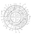
- FIG. 2 is a plan view of the frame member 16
- FIG. 3 is a cross-sectional view taken along line 3-3 in FIG. 2
- FIG. 4 is a plan view of the elastic body
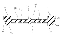
- FIG. 5 is a cross-sectional view taken along line 5-5 in FIG. -6 sectional view
- FIG. 7 is a sectional view taken along the line 7-7 in FIG. 4
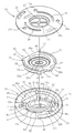
- FIG. 8 is an exploded perspective view of the partition member
- FIG. 9 is a sectional view of the partition member in the assembled state (the same sectional portion as FIG. 1)
- FIG. 10 is a plan view showing a state before the elastic body is fitted to the frame member and the cover member is attached
- FIG. 11 is a sectional view taken along the line 11-11 in FIG. 10
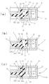
- FIGS. 12 and 13 are sectional views for explaining the operation.
- . 13 shows a portion corresponding to the 13-13 cross section of FIG.
- the partition member 6 is composed of three members in which an elastic body 30 is sandwiched between the lid member 15 and the frame member 16 that are separated vertically.
- the lid member 15 is provided with a central upper opening 18 in the center and a pair of left and right arc-shaped relief holes 19 on the outer peripheral side thereof.
- Reference numeral 20 denotes a main liquid chamber side entrance / exit of the orifice passage.
- an arc-shaped groove 22 constituting the orifice passage 8 (FIG. 1) is formed in an arc shape along the outer periphery, and the length thereof is about 3/4 of the length. It is provided in an arc shape. 2 indicates a direction in which the working fluid flows from the main liquid chamber 5 to the sub liquid chamber 7 in the arc-shaped groove 22.
- the arc-shaped groove 22 is partitioned from the inner peripheral side portion of the frame member 16 by an annular partition wall 23 forming an inner peripheral wall thereof, and the inside of the annular partition wall 23 forms a fitting space for the elastic body 30 to be fitted.
- a central lower opening 28 is provided at the center of the bottom of the fitting space, and a pair of left and right arc-shaped relief holes 29 are provided on the outer peripheral side thereof.
- the elastic body 30 forms a movable film portion 31 having a thin central portion, and forms a thick outer peripheral portion 32 whose outer peripheral portion surrounding the movable film portion 31 is thicker than the movable film portion 31.
- a substantially V-shaped relief valve 33 is formed on the thick outer peripheral portion 32.
- the relief valves 33 are formed in a circular arc shape and are long in the circumferential direction (approximately 1 ⁇ 4 circumference), are arranged to face each other at an interval of 180 ° across the center of the elastic body 30, and are provided as a pair.
- the central upper opening 18 and the central lower opening 28 face above and below the movable film portion 31 (see FIGS. 9 and 11).
- the relief holes 19 and 29 face above and below the relief valve 33 (see FIG. 7)
- the main liquid chamber side entrance 20 faces one end in the length direction of the arc-shaped groove 22 (see FIG. 9).
- a relief passage 39 that communicates the relief holes 19 and 29 is formed between the annular partition wall 23 and the elastic body 30 (relief valve 33).
- the relief valve 33 opens and closes the relief passage 39, and is normally closed.
- the relief valve 33 is opened only when the main liquid chamber 5 reaches a predetermined negative pressure at the time of a large input, and from the sub liquid chamber 7 side to the main liquid chamber 5 side.
- the hydraulic fluid is relieved. Note that the other end in the length direction of the arc-shaped groove 22 faces a secondary liquid chamber side entrance 49 (see FIG. 2) provided in the frame member 16.
- the lid member 15 is a substantially disk-shaped member made of an appropriate material such as a light metal or hard resin having a circular shape in plan view and rigidity.
- the central portion of the lid member 15 forms a central step portion 17 that is one step lower, and a central upper opening 18 that communicates with the main liquid chamber 5 is formed therein and is defined by a cross-shaped deformation restriction frame 18a.
- the deformation restricting frame 18a abuts and supports the upper surface side of the movable film portion 31 when it is excessively elastically deformed to restrict excessive elastic deformation.
- a pair of relief holes 19 forming an arc-shaped elongated hole of about 90 ° is approximately 1 ⁇ 4 round, and the lid member 15 has a length of about 1 ⁇ 4 round at 180 ° intervals on the same circumference. Opposed to the center.
- Reference numeral 20 denotes a main liquid chamber side entrance of the orifice passage 8 formed in the lid member 15.
- 21a is a positioning hole into which a positioning pin, which will be described later, is fitted.
- a total of three positioning holes are formed and are unevenly arranged in the circumferential direction in order to prevent erroneous assembly. The arrangement is shifted from the relief hole 19 and the main liquid chamber side entrance / exit 20. It is in the position.
- the frame member 16 will be described with reference to FIGS. 8 and 2, 3, 9 to 11.
- the frame member 16 has a circular shape in plan view and is made of an appropriate material such as a light metal or hard resin having rigidity.
- a central lower opening 28 communicating with the auxiliary liquid chamber 7 is formed in the center of the bottom of the fitting space with the elastic body.
- Reference numeral 28a denotes a deformation restriction frame on the sub liquid chamber side, which abuts and supports the lower surface side of the movable film portion 31 when it is excessively elastically deformed to restrict excessive elastic deformation.
- the inner peripheral surface of the annular partition wall 23 forms a two-sided width portion 46a, 46b facing each other partially in a planar shape.
- the two-sided width portions 46a and 46b are parallel to the opposite positions of the circumference of an assumed circle (indicated by phantom lines in FIG. 2) inscribed by the circular portions 23a and 23b on the inner circumferential surface of the annular partition wall 23 in plan view.
- a straight line corresponding to the cut string is formed, and the length thereof is approximately the length of the string corresponding to a substantially 1/4 circular arc of the assumed circle.
- the facing surfaces form a vertical plane parallel to the central axis.
- planar two-surface width portions and circular portions 23a and 23b are alternately arranged at intervals of approximately 90 °.
- the circular portions 23a and 23b also have a length of about 1 ⁇ 4 circumference of the assumed circle, and the circular portions 23a and 23b and the two-surface width portions 46a and 46b are arranged to face each other.
- the bottom portion of the fitting space inside the annular partition wall 23 forms an annular bottom portion 25a having a predetermined distance from each inner peripheral surface of the circular portions 23a and 23b of the annular partition wall 23, and the inner periphery portion is a ring having a low protruding height.
- a partition-shaped annular stopper portion 25b is formed. The annular stopper portion 25 b faces the lower central opening 28.
- the annular bottom portion 25a is formed with a constant width on the entire circumference, and relief holes 29 are formed between the inner peripheral surfaces of the circular portions 23a and 23b of the annular partition wall 23.
- each plane is in contact with or close to the outer periphery of the annular bottom portion 25a, and when this contact or closest portion is P, it expands toward both sides in the circumferential direction across the point P.
- the corner 51 to be made is made. Since each corner portion 51 is formed on both sides of each two-sided width portion 46a, 46b, a total of four corner portions 51 are formed on the entire circumference.
- the planar shape is generally triangular or trapezoidal, but part of the relief valve 33 is inserted between the circumferential ends of the circular portions 23a and 23b and the annular bottom 25a at the longitudinal ends of the relief valve 33. When this part is included, it forms an irregular trapezoidal shape.
- the surface of each corner portion 51 forms a tapered surface 50, and is inclined downward toward the annular bottom portion 25a (see FIG. 3).
- the radial width of the annular partition wall 23 changes, and the upper surface sandwiched between the two-sided width portions 46a and 46b and the arc-shaped groove 22 has a substantially crescent-shaped enlarged portion 23c.
- the radial width of the enlarged portion 23 c is wider than the radial width of each upper surface of the circular portions 23 a and 23 b sandwiched between the arc-shaped groove 22 and the relief hole 39.
- an intermediate support portion 52 that crosses in the radial direction is formed at the longitudinal intermediate portion that is the circumferential direction of the annular partition wall 23.
- the intermediate support portion 52 is a rib-like member that connects the outer peripheral portion of the annular bottom portion 25a and the inner peripheral surface of the annular partition wall 23, and the relief hole 39 is relatively long, approximately 1 ⁇ 4 circumference of the assumed circle. Reinforce the part.
- the upper end surface forms a tapered surface 53 and supports the inclined surface 34 of the relief valve 33 from below (see FIG. 13).
- the relief valve 33 is prevented from sagging, which becomes comparatively long and the middle portion is liable to fall, and has a function of preventing excessive deformation at the time of large input, which will be described later.
- the intermediate support portion 52 is integrally provided along the inner peripheral surface of the annular partition wall 23 with a predetermined protruding height in the central axis direction.
- the position and the inclination of the tapered surface 53 are appropriately set in consideration of the shape of the inclined surface 34 of the relief valve 33 and the state of excessive deformation thereof.
- the number is also arbitrary, and two relief valves 33 are provided at equal intervals in the length direction of the relief valve 33.
- the annular bottom portion 25a forms an annular recess between the inner peripheral surface of the annular partition wall 23 and the annular stopper portion 25b, and the lower portion 32a of the thick outer peripheral portion 32 is fitted therein. ing.
- the annular stopper portion 25b is positioned on the inner peripheral side of the lower portion 32a, and when the thick outer peripheral portion 32 is pulled radially inward due to elastic deformation of the movable film portion 31, the lower portion 32a is pulled out radially inward. Fix it so that it will not.
- the upper portion of the thick outer peripheral portion 32 is positioned at the stepped portion 17 in the central portion of the lid member 15 to prevent falling inward in the radial direction and improving the opening / closing accuracy of the relief valve 33. It contributes to.
- the lower portion 32a is a restraint portion that is fixed by being sandwiched from above and below by the lid member 15 and the frame member 16 by being fitted and positioned in a tapered annular partition wall, and the annular support portion of the movable film portion 31 is provided. There is no.
- one of the opposing enlarged portions 23 c is formed with a misassembly prevention groove 48, and the misassembly prevention protrusion 42 provided on the elastic body 30 (see FIG. 11). Is designed to fit.
- Reference numeral 21 in FIG. 8 denotes three positioning pins, which protrude from the peripheral upper surface of the annular partition wall 23 and are inserted into the positioning holes 21a formed in the lid member 15 to crimp the tip.
- the lid member 15 and the frame member 16 are positioned and integrated, and the lid member 15 and the frame member 16 are unable to rotate relative to each other.
- the elastic body 30 is made of an appropriate elastic material such as rubber, and has a shape and a size that can be fitted into the fitting space of the frame member 16. That is, the two-surface width portions 46a and 46b corresponding to the chords obtained by cutting away the opposite positions of an assumed circle (shown by phantom lines in FIG. 4) inscribed by the outer peripheral portion having the same diameter as the inner periphery of the annular partition wall 23 are provided. A pair of relief valves 33 are formed on the outer peripheral portion 32 between the pair of two-side width portions 40a and 40b.
- a total of four corner portions 45 are provided in the circumferential direction at the boundary between the two-surface width portions 40 a and 40 b and the relief valve 33.
- the two-sided width portions 40a and 40b and the relief valve 33 are alternately arranged in the length direction, and the length of the relief valve 33 in the length direction is approximately 1/4 of the assumed circle, and the two-sided width portions 40a and 40b. Is approximately the length of the chord corresponding to approximately 1 ⁇ 4 arc of the assumed circle.
- the corner portion 45 and the two-surface width portions 40a and 40b are rotation stoppers in the present invention.
- the two-sided width portions 40a and 40b form a vertical plane in which each facing surface is parallel to the central axis, and when fitted to the frame member 16, overlaps with the two-sided width portions 46a and 46b of the frame member 16 to prevent rotation. It has come to make.
- the two-surface width portions 40a and 40b and the corner portion 45 constitute a detent portion in the present invention.
- the side surface of the outer peripheral portion of the relief valve 33 forms a slope 34, and the upper portion thereof forms a seal portion 36 that comes into close contact with the inner peripheral surface of the annular partition wall 23 when fitted to the frame member 16. 39 is closed.
- the corner portion 45 is a portion that overlaps the corner portion 51 of the frame member 16, the outer wall surface forms a tapered surface 44, and the slope corresponding to the tapered surface 50 of the corner portion 51 Has shape and dimensions.
- the corner part 51 and the two-surface width parts 46a and 46b form a fitting part in the present invention.
- the corner portion 45 is a thick-walled portion where the relief valve 33 is continuous, and when the relief valve 33 receives the hydraulic pressure of the main fluid chamber 5 and is pulled toward the middle portion in the length direction.
- a support portion is provided for firmly supporting the longitudinal end portion of the relief valve 33 without falling in the pulling direction.
- the thick two-face width portions 46a and 46b including the corner portion 45 are sandwiched between the pair of relief valves 33 by connecting the end portions in the length direction of the pair of relief valves 33 facing each other. Since the entire portion supports the lengthwise end portions of the relief valve 33 with a sufficiently long thick portion corresponding to approximately 1 ⁇ 4 of the outer peripheral length, the support rigidity for the relief valve 33 is sufficiently increased. In addition to being able to exert a reliable detent function.
- the elastic bodies 30 when the elastic body 30 is fitted to the frame member 16, the elastic bodies 30 are accurately positioned by tapering the tapered surfaces 44 and 50 of the corner portions 45 and 51 at the four corners.
- the relief valve 33 can be set at an accurate position.
- the partition member 6 can be easily assembled by taper alignment at the time of assembly, and the elastic body 30 can be accurately positioned with respect to the frame member 16, and the relief passage 29 can be maintained constant.
- the relief passage 29 can be kept constant by reliable rotation prevention during subsequent use, a predetermined relief flow rate can be secured when the cavitation phenomenon occurs at the time of large input, and the occurrence of the cavitation phenomenon is prevented. You will be able to stop without fail.
- the elastic body 30 when the elastic body 30 is fitted to the frame member 16, the upper inner wall surface of the corner portion 51 and the outer wall surface of the corner portion 45.
- a slight gap 55 is provided between the upper portion.
- the enlarged partition 22 a (FIG. 2) is formed at the end of the arc-shaped groove 22, so that the annular partition 23 in the vicinity forms a thin portion 23 d, and in the vicinity of the thin portion 23 d
- the corner portion 45 is a portion where there is a possibility of liquid leakage from the main liquid chamber side to the sub liquid chamber side through the gap 55 due to the elastic deformation of the thick outer peripheral portion 32 at the time of large input. And 51 can be prevented from leaking with high sealing performance.
- the positioning by the corner portion 45 and the high sealing performance are similarly realized on the two-surface width portion 46 b side where the misassembly prevention groove 48 and the misassembly prevention protrusion 42 are provided.
- a slight gap 56 is also provided between the misassembly prevention groove 48 and the misassembly prevention protrusion 42, but liquid leakage from this gap 56 is also prevented.
- the upper portion of the annular partition wall 23 provided with the misassembly prevention groove 48 also forms a thin portion 23e.
- a plurality of seals 57a to 57d are formed on the surface of the elastic body 30 as shown in FIG.
- a plurality of concentric ring-shaped ribs 31a, 31b, and 31c are integrally projected on the upper surface or the lower surface of the movable film portion 31 of the elastic body 30, and the movable film portion 31 is
- the upper and lower deformation regulating frames 18a and 28a are initially brought into contact with each other with a small contact area.
- the elastic body 30 when the elastic body 30 is fitted into the fitting space of the frame member 16 and the misassembly prevention protrusion 42 is fitted into the misassembly prevention groove 48, the elastic body 30 is misassembled. While being prevented, the two-surface width portions 40a and 40b corresponding to the two-surface width portions 46a and 46b can be brought into contact with each other accurately and fitted. Then, after positioning each positioning pin 21 through the positioning hole 21a of the lid member 15 and then positioning the tip of each positioning pin 21 while pressing the lid member 15 against the elastic body 30 with a predetermined pressure, the partition member 6 is obtained. Are integrated and assembled, and the taper surfaces 44 and 50 are tapered together to obtain high sealing performance.
- the elastic body 30 since the elastic body 30 is accurately positioned, the relief holes 19 and 29 and the relief valve 33 can be reliably and easily aligned.
- two planar outer surfaces of the two-surface width portions 46 a and 46 b that are high-rigidity support portions are formed on the inner peripheral surface of the annular partition wall 23 that also has a planar shape. Since the elastic body 30 is in contact with the surface width portions 46a and 46b in a wide area, the elastic body 30 can be reliably prevented from rotating even at the time of a large input by using the two surface width portions 40a and 40b on the outer peripheral portion.
- the relief valve 33 has a concave portion 35 formed integrally with a part of the thick outer peripheral portion 32, and a radially outer wall portion surrounding the concave portion 35 is a sub-liquid.
- An inclined surface 34 is formed so as to open obliquely upward from the chamber 7 side toward the main liquid chamber 5 side, and the tip of this inclined surface is thick and the outer surface side is liquid to the inner peripheral surface of the annular partition wall 23.
- the seal part 36 which closely adheres is made.
- the inclined surface 34 is a main part of the relief valve 33. As shown in FIG. 7, the inclined surface 34 hardly bends normally and is positioned so as to cover the upper portion of the relief passage 39, so that the relief passage 39 is closed. The hydraulic fluid easily flows through the hydraulic fluid from the secondary liquid chamber 7 side to the main liquid chamber 5 side. On the main liquid chamber 5 side of the relief valve 33, a concave portion 35 having a substantially V-shaped cross section and opening toward the main liquid chamber 5 is formed.
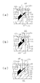
- FIG. 12A and 12B illustrate the operation of the relief valve 33.
- FIG. 12A shows a state in which a large input is entered when the relief valve 33 is closed, and the slope 34 is greatly deformed by bulging downward to cause a large input.
- the hydraulic pressure F1 is received.
- the seal portion 36 slides on the inner peripheral surface of the annular partition wall 23 to maintain close contact, and does not relieve the hydraulic fluid from the lower liquid chamber 7 side to the main liquid chamber 5 side.
- (B) is a state in which the slope 34 is excessively deformed due to a larger hydraulic pressure F2, and a part of the seal portion 36 is irregularly deformed to be separated from the annular partition wall 23 and the sealing performance is impaired, so that the hydraulic fluid leaks out. Indicates.
- the amount of hydraulic fluid to be sent from the main fluid chamber 5 to the auxiliary fluid chamber 7 via the orifice passage 8 is reduced, so that the damping force is reduced.
- Even in the state where leakage does not occur if the inclined surface 34 is excessively deformed, the hydraulic pressure in the main liquid chamber 5 is absorbed more than necessary, so that the damping force is also lowered.
- the present invention can prevent such excessive deformation by the intermediate support portion 52, as will be described later.
- (C) shows a state in which, after a large input, the vibration direction is reversed, the volume of the main liquid chamber 5 becomes the expansion direction, and the main liquid chamber becomes negative pressure.
- the inclined surface 34 is sucked toward the main liquid chamber 5 side, and simultaneously the working liquid on the sub liquid chamber 7 side pushes up the inclined surface 34 from below, so that the inclined surface 34 is deformed so as to be turned from the tip side, and eventually the seal portion 36.
- FIG. 13 is a diagram for explaining the operation of the intermediate support portion 52, and shows a state in which an excessive hydraulic pressure F2 is applied due to an excessive input, as in FIG.
- the tapered surface 53 of the intermediate support portion 52 supports the lower portion of the slope 34 at the intermediate portion in the length direction of the relief valve 33. Therefore, the excessive deformation of the inclined surface 34 can be prevented by supporting the intermediate portion in the length direction where the deformation becomes the largest. For this reason, it is possible to prevent leakage due to excessive deformation and prevent a decrease in damping force.
- the relief area is increased by increasing the opening area of the relief holes 19 and 29 in order to secure a large relief amount, the excessive deformation of the relief valve 33 can be easily and reliably prevented. Further, since unnecessary absorption of the hydraulic pressure in the main liquid chamber 5 due to excessive deformation does not occur, the reduction of the damping force can be prevented in this respect as well.
- the length of the relief valve 33 is increased to about 1/4 of the circumference of the assumed circle obtained by extending the relief valve in the circumferential direction, the hydraulic fluid flow rate at the time of relief is increased and the cavitation phenomenon is efficiently performed. Can be suppressed.
- the number of relief valves 33 can be halved, and the relief valves 33 can be used as fixed portions at both ends in the length direction.
- the volume of the thick outer peripheral portion 32 can be increased to increase the support rigidity, and liquid leakage can be prevented.
- the most difficult part of the relief valve 33 to bend is the connection part with the corner part 45 at the end in the length direction.
- the number of such difficult parts to be bent can be halved.
- the operability of the relief valve 33 can be relatively improved.
- the anti-rotation portion has an outer periphery of the thick outer peripheral portion 32 between the left and right relief valves 33 regardless of the width of the two surfaces.
- a non-circular portion having a polygonal shape can also exhibit a detent function.
- FIG. 14 is a cross section (corresponding to the cross section along line 14-14 in FIG. 15) taken along the central axis CL of the liquid seal vibration isolator according to the second embodiment of the present invention.
- the center axis CL is also a center line of the elastic body 130 described later.
- This engine mount connects between a first mounting member 101 mounted on an engine (not shown) that is a vibration source and a second mounting member 102 mounted on a vehicle body (same as above) on the vibration receiving side.
- an insulator 103 is made of a known vibration-proof elastic member such as rubber, and is an elastic body that serves as a vibration-proof main member against vibration.
- vibration input to the first mounting member 101 from the main vibration input direction Z is the insulator. It is absorbed by the elastic deformation of 103.
- the input direction Z of the main vibration is parallel to the center line CL shown in the figure.
- a view along the Z direction from above is referred to as a plan view (plan view).
- the insulator 103 has a substantially frustoconical cross section and is provided with a dome-shaped portion 104 on the inner side.
- the dome-shaped portion 104 forms a recess opened downward in FIG. 14, and an incompressible hydraulic fluid is sealed in the recess.
- the main liquid chamber 105 is formed.
- the main liquid chamber 105 is separated from the sub liquid chamber 107 by the partition member 106, and communicates with the sub liquid chamber 107 through the partition passage 106 by the orifice passage 108.
- the auxiliary liquid chamber 107 is formed between the diaphragm 110 and the partition member 106, and the diaphragm 110 is a part of the wall portion.
- the partition member 106 has a movable film portion (described later) that absorbs fluid pressure fluctuations in the orifice passage 108 and the main liquid chamber 105, and a relief for relieving the hydraulic fluid from the sub liquid chamber 107 side to the main liquid chamber 105 side when a large input is applied.
- a valve (same as above) is provided.
- the orifice passage 108 is a damped orifice set so as to resonate with a low frequency vibration such as a shake vibration of about 10 to 11 Hz.
- the second mounting member 102 includes a cylindrical outer tube fitting 111, and the outer tube fitting 111 is fitted to a holder (not shown) or attached to the vehicle body via a bracket if necessary.
- the outer tubular fitting 111 is a part of the second mounting member 102. Moreover, it forms the outer peripheral wall of the orifice passage 108 together with the extension 112 of the insulator 103 integrated inside.
- the extension portion 112 of the insulator 103 extends downward as much as the height of the partition member 106 and integrally covers the inner surface of the outer cylinder fitting 111.
- the extension 112 covers the outer periphery of the partition member 106 and seals between the orifice passage 108 and the outer tube fitting 111.
- a portion facing the main liquid chamber 105 at the upper portion of the extension portion 112 forms a thick-walled step 114, where the outer peripheral end of the partition member 106 is positioned.
- the diaphragm 110 includes a thin-walled portion 110a that is a main body portion and a thick-walled outer peripheral portion 110b that is integrally formed on the outer peripheral portion thereof, and a fixing ring 110c is inserted and integrated with the outer peripheral portion 110b. From the outer peripheral surface of the fixing ring 110c, a seal portion 110d, which is a part of the outer peripheral portion 110b, protrudes radially outward. The fixing ring 110c is inserted into the outer cylindrical fitting 111 through the seal portion 110d and fixed by caulking.
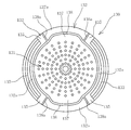
- FIG. 15 is a plan view of the partition member with the upper frame member removed
- FIG. 16 is a cross-sectional view taken along line 16-16 in FIG. 15 (the upper frame member is also shown in the same cross-sectional area)
- FIG. It is a perspective view exploded and shown in a member.
- the partition member 106 is composed of three members in which an elastic body 130 is sandwiched between the upper frame member 115 and the lower frame member 116 that are separated vertically.
- the upper frame member 115 functions as a lid member for the lower frame member 116, and a central upper opening 118 is provided at the center, and a pair of left and right arc-shaped relief holes 119 are provided on the outer peripheral side thereof.
- Reference numeral 120 denotes an opening on the main liquid chamber side of the orifice passage.
- Reference numeral 121a denotes a positioning hole into which the positioning pin 121 of the lower frame member 116 is fitted.
- a concave portion 122 constituting the orifice passage 108 (FIG. 14) is formed in an arc shape along the outer periphery, and the length thereof is a circle having a length of about 3/4. It is provided in an arc shape.
- the direction indicated by the arrow A in FIG. 15 indicates the direction in which the hydraulic fluid flows from the main liquid chamber 105 to the sub liquid chamber 107 in the recess 122.
- the recess 122 is partitioned from an inner peripheral side portion of the lower frame member 116 by an annular partition wall 123 forming an inner peripheral wall thereof, and an inner side of the annular partition wall 123 forms a fitting space 127 into which the elastic body 130 is fitted.
- a central lower opening 128 is provided at the center of the bottom of the fitting space 127, and a pair of left and right arc-shaped relief holes 129 are provided on the outer peripheral side thereof.
- the elastic body 130 forms a movable film portion 131 having a thin central portion, and forms a thick outer peripheral portion 132 in which an outer peripheral side portion surrounding the movable film portion 131 is thicker than the movable film portion 131.
- a substantially V-shaped relief valve 133 is formed on the thick outer peripheral portion 132.
- the relief valves 133 are formed in a pair of arcs that are long in the circumferential direction (opening angle is approximately 120 °, approximately 1/3 circumferential length) and are opposed to each other with an interval of 180 ° across the center of the elastic body 130. It has been.
- This relief valve 133 is provided only by one set unlike the conventional one provided by a total of two sets, which are a pair of opposed valves.
- the central upper opening 118 and the central lower opening 128 face the upper and lower sides of the movable film portion 131 (FIG. 16). 17), relief holes 119 and 129 face the upper and lower sides of the relief valve 133 (see FIGS. 16 and 17), and the main liquid chamber side opening 120 faces an enlarged end 122a formed at one end in the length direction of the recess 122. (See FIG. 15).
- the lower portion of the thick outer peripheral portion 132 is positioned by being fitted into the annular groove 150 of the lower frame member 116, and is further fixed by being sandwiched and fixed between the upper frame member 115 and the lower frame member 116 from above and below.
- a relief passage 139 that communicates relief holes 119 and 129 is formed between the annular partition wall 123 and the elastic body 130 (relief valve 133).
- the relief valve 133 opens and closes the relief passage 139 and is normally closed.
- the relief valve 133 is opened only when the main liquid chamber 105 reaches a predetermined negative pressure at the time of large input, and from the sub liquid chamber 107 side to the main liquid chamber 105 side.
- the hydraulic fluid is relieved.
- the other end in the lengthwise direction of the recess 122 faces the secondary liquid chamber side opening 149 (see FIG. 15) provided in the lower frame member 116.
- the inner side and the lower side of the recess 122 are surrounded by the annular partition wall 123 and a flange 116a projecting radially outward from the lower end of the annular partition wall 123, and the upper side is an outer peripheral extension 115a (from the annular wall 123) of the upper frame member 115. It is surrounded by a portion extending radially outward), but the outer side is open. This open portion is covered with the outer cylinder fitting 111 and the extension 112 inside thereof during the entire assembly to form the orifice passage 108. The lower end of the extension portion 112 abuts on the flange 116a, and the abutment portion is sealed by crushing a seal protrusion that is integrally formed in advance with the lower end of the extension portion 112.
- An outer peripheral extending portion 115 a of the upper frame member 115 is in contact with an intermediate portion in the vertical direction of the extending portion 112.
- the outer peripheral extension 115a is smaller in diameter than the flange 116a by the thickness of the extension 112.
- the orifice passage 108 has an outer peripheral wall as an extension portion 112 and an outer cylinder fitting 111 instead of the lower frame member 116, and the extension portion 112 and the outer cylinder fitting 111 are used as a constituent material of the orifice passage 108. Therefore, it is not necessary to provide the outer wall of the orifice passage 108 in the lower frame member 116, and the orifice passage 108 can be arranged closer to the outer peripheral side.
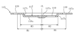
- FIGS. 18 is a plan view of the upper frame member
- FIG. 19 is a cross-sectional view taken along line 19-19 of FIG.
- the upper frame member 115 is a substantially disk-shaped member made of an appropriate material such as light metal or hard resin having a circular shape in plan view and rigidity.
- the central portion of the upper frame member 115 is a non-circular central step portion 117 that is lowered by one step, and a central upper opening 118 that communicates with the main liquid chamber 105 is formed therein, and is partitioned by a plurality of deformation restriction frames 118a that are radially provided. (Only a few of them are designated by way of example).
- the deformation restricting frame 118a abuts and supports the upper surface side of the movable film portion 131 when it is excessively elastically deformed, and restricts excessive elastic deformation.
- a pair of relief holes 119 forming an arc-shaped elongated hole of about 90 ° is approximately 1/3 round, and the upper frame member 115 is spaced 180 ° on the same circumference.
- a center fixing convex portion 117a protruding downward is formed at the center of the upper frame member 115.
- Reference numeral 120 denotes a main liquid chamber side opening of the orifice passage 108 formed in the upper frame member 115.
- a total of three positioning holes 121a are formed and unevenly arranged in the circumferential direction to prevent erroneous assembly, and the arrangement is shifted from the relief holes 119 and the main liquid chamber side opening 120.
- C1 is a large-diameter assumed circle having the same curvature radius as that of the outer circumferential arc of the relief hole 119.
- C2 is a small-diameter assumption circle having the same curvature radius as the small-diameter portion 117b that is a portion along the relief hole 119 in the outer peripheral portion of the central step portion 117.
- the portion located between the adjacent end portions of the left and right relief holes 119 forms an enlarged portion 117c that protrudes radially outward from the small diameter assumed circle C2 and approaches the large diameter assumed circle C1. .
- the outer peripheral portion of the center step portion 117 is a non-circular shape obtained by deforming a part of the assumed small diameter circle C2.
- C3 is an assumed circle in contact with a part of the outer periphery of the enlarged portion 17c.
- the elastic body 130 is fitted with the outer peripheral side of the thick outer peripheral part 132 to the inner peripheral side of the annular partition wall 123, and the inner peripheral side is fitted with the outer peripheral part of the central step part 117 in the upper frame member 115. Therefore, the large diameter assumed circle C1 coincides with the outer diameter of the thick outer peripheral portion 132 and the inner diameter of the annular partition wall 123 (both are diameters of portions other than the two-surface width portion described later). Further, the assumed small diameter circle C2 coincides with the inner diameter of the thick outer peripheral portion 132 and the outer diameter of the central step portion 117 in the upper frame member 115 (both are the diameter of the small diameter portion).
- the upper part of the thick outer peripheral part 132 is positioned in the level
- the elastic body 130 is made of a suitably elastic material such as rubber, and has a shape and a size that can be fitted into the fitting space 127 (FIG. 17) of the lower frame member 116.
- the thick outer peripheral portion 132 is overlapped with the large-diameter assumed circle C1 and a pair of valve portions 132a disposed opposite to each other with the center O interposed therebetween, and a pair of two-surface widths disposed opposite to each other with the center O interposed therebetween.
- a total of four corner portions 135 are provided at both ends in the length direction of the valve portion 132a, and each corner portion 135 is disposed so as to face the center O.
- the two-sided width portion 136 corresponds to a shape obtained by cutting the opposite position of the large-diameter assumed circle C1 in parallel, and the straight portion formed on the outer peripheral side of the two-sided width portion 136 is a chord of the large-diameter assumed circle C1. It is a corresponding part, and it is provided as a pair facing each other, and each is parallel.
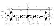
- the elastic body 130 is non-circular as a whole. That is, as shown in FIG. 20, each radius of the assumed large diameter circle C1 and the assumed small diameter circle C2 is R1 and R2, and the radius at the midpoint M of the two-surface width portion 136 (the distance between M and the center of the elastic body 130). ) Is a radius R4, R4 is shorter than R1 by ⁇ R due to the formation of the notch 134, as shown in FIG. R3 is the radius of the assumed circle C3.
- the movable film portion 131 has a noncircular shape in which the shape of the outer peripheral portion that is a boundary portion with the thick outer peripheral portion 132 corresponds to the outer peripheral portion of the central stepped portion 117. That is, the portion along the valve portion 132a forms a small diameter portion and overlaps the small diameter assumed circle C2, while the portion along the two-surface width portion 136 forms an enlarged portion 137 and projects outward in the radial direction of the small diameter assumed circle C2. By entering the width portion 136, the entire movable film portion 131 has a non-circular shape.
- the two-sided width portion 136 and the valve portion 132a are alternately arranged in the length direction, and the length of each relief valve 133 in the length direction is substantially 1/3 of the large diameter assumed circle C1, and the two-sided width portion 136
- the outer peripheral part that forms a straight line in a plan view is approximately the length of the chord corresponding to approximately 1/6 arc of the large diameter assumed circle C1.
- the corner part 135 and the two-sided width part 136 are rotation stoppers in the present invention.
- the two-sided width portion 136 forms a vertical plane in which each facing surface is parallel to the central axis.
- the radial width of the notch 134 shown as the radial thickness in FIG. 21 is the narrowest at the middle point M portion and gradually increases toward the corner portion 135.
- the radial width d1 of the two-surface width portion 136 at the middle point M is slightly narrower than the radial width of the valve portion 132a (the radial width at the base portion excluding the relief valve 133) d2.
- the radial width d3 of the corner portion 135 is several times wider than the radial width d1 of the midpoint M portion of the two-surface width portion 136 and the radial width d2 of the valve portion 132a. ing. A lower portion of the outer wall surface of the corner portion 135 forms a tapered surface 135a.
- the corner portion 135 is a thick portion where the valve 132a is continuous, and when the relief valve 133 receives the hydraulic pressure of the main fluid chamber 105 and is pulled toward the middle portion in the length direction, A support portion is provided for firmly supporting the longitudinal end portion of the relief valve 133 without falling in the pulling direction.
- a non-circular annular seal 138 is formed on the surface of the elastic body 130 along the outer periphery of the movable film portion 131.
- a radial seal 138a extending continuously outward in the radial direction from the annular seal 138 is also formed on the surface of each corner portion 135. With these seals, the gap between the movable film portion 131 and the valve portion 132a is securely sealed when the partition member 106 is assembled.
- a convex part 131a protrudes up and down at the center of the movable film part 131 in the elastic body 130, and is provided integrally.
- a plurality of hemispherical small protrusions 131b are concentrically surrounding the convex part 131a. Are projected integrally from the upper and lower surfaces.
- the small protrusions 131b are arranged at equal intervals on one concentric circle, and a plurality of concentric rows are provided in the radial direction (six rows in this example).
- the small protrusion 131b makes initial contact with the upper and lower deformation regulating frames 118a (FIG. 18) and 128a (FIG. 24) with a small contact area to reduce the hitting sound. ing.
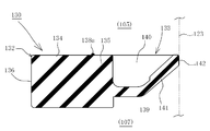
- the relief valve 133 is formed integrally with a part of the valve portion 132a so as to form a substantially V-shaped cross section having a concave portion 140 opened toward the main liquid chamber 105.
- a radially outer wall portion surrounding the recess 140 forms a slope 141 provided so as to open obliquely upward from the sub liquid chamber 107 side toward the main liquid chamber 105 side, and a tip portion of the slope 141
- the seal portion 142 is thick and has an outer surface that is liquid-tightly adhered to the inner peripheral surface of the annular partition wall 123.
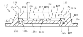
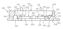
- FIGS. 24 is a plan view of the lower frame member 116
- FIG. 25 is a cross-sectional view taken along the line 25-25 in FIG. 24
- FIG. 26 is a cross-sectional view taken along the line 26-26 in FIG. is there.
- the lower frame member 116 has a circular outer periphery in plan view, and is made of an appropriate material such as a light metal or a hard resin having rigidity.
- An annular partition wall 123 is provided inside the outer periphery, and a non-circular central step 157 is also provided inside the annular partition wall 123 with a non-circular annular groove 150 interposed therebetween.
- the inner peripheral surface of the annular partition wall 123 is a non-circular shape having a pair of circular portions 123a and 123b that are opposed to each other and overlap a large-diameter assumed circle C1 (radius R1), and a pair of two-surface width portions 126 that are also opposed to each other. Eggplant.
- the circular portions 123a and 123b have the same inner circumference on the same large-diameter assumed circle C1, but the outer circumference has a different radius, and the outer circumference radius of the round portion 123a in which the orifice passage recess 122 is not formed is R5.
- the outer peripheral radius of the circular portion 123b where R is formed is R6 (R5> R6), and the radial width of the circular portion 123a is wider than the radial width of the circular portion 123b on the other side by the difference of this radius (FIG. 24). reference).
- the radial widths of the portions 124a and 124b where the opposing two-surface width portions 126 are formed are also different from each other, and the portion 124a on the side where the enlarged end portion 122a formed at one end in the length direction of the concave portion 122 is thin.
- the radial width is narrow with a substantially crescent shape, and the portion 124b on the side of the opposite liquid chamber side opening 149 on the opposite side has a thicker crescent shape with a wide radial width.
- a circular portion 123a having an opening angle of approximately 120 ° and a substantially 1/3 circular arc and a two-surface width portion 126 having an opening angle of approximately 60 ° are alternately opposed to each other.
- a total of four corner portions 125 are provided at both ends in the length direction of the circular portion 123a, and each corner portion 125 is disposed opposite to the center O.
- the two-sided width portion 126 is partially planar, and when the elastic body 130 is fitted inside the annular partition wall 123, the two-sided width portion 136 closely overlaps.
- the annular groove 150 is a groove that fits and supports the lower portion of the thick outer peripheral portion 132 of the elastic body 130, and is opened upward so that the shape of the groove bottom in plan view matches the shape of the lower end surface of the thick outer peripheral portion 132. It is lower than the step portion 157.
- the groove width of the annular groove 150 varies in the circumferential direction, the distance between the circular portions 123a and 123b of the annular partition wall 123 and the small diameter portion 157b of the central step portion 157 is wide, and the distance between the two-surface width portion 126 and the enlarged portion 157c is narrow. It has become.
- the central step portion 157 is a portion that supports the lower surface of the movable film portion 131 with a space therebetween, and the shape of the outer periphery in plan view matches the outer shape of the movable film portion 131. Therefore, it forms a non-circular shape having a small-diameter portion 157b that overlaps the small-diameter assumed circle C2 and an enlarged portion 157c that protrudes radially outward from the small-diameter assumed circle C2.
- the central step portion 157 is located on the inner side of the inner peripheral surface of the annular partition wall 123 and the annular groove 150, forms a step portion having a non-circular shape in plan view that is one step higher in the central portion, and projects upward in the central portion.
- a center fixed convex portion 157 a is formed so as to initially contact the convex portion 131 a provided at the center of the movable film portion 131.
- a central lower opening 128 that communicates with the main liquid chamber 105 is formed around the center fixing convex portion 157a, and is partitioned by a plurality of deformation regulation frames 128a that are radially formed (only a few are respectively illustrated as examples) Instruct).
- the deformation regulating frame 128a abuts and supports the lower surface side of the movable film portion 131 when the movable film portion 131 is excessively elastically deformed to restrict excessive elastic deformation.
- the inner peripheral side of the annular groove 150 is surrounded by the outer peripheral wall where the small-diameter portion 157b or the enlarged portion 157c rises. Therefore, when the lower part of the thick outer peripheral part 132 is fitted into the annular groove 150, the outer peripheral wall where the small diameter part 157b or the enlarged part 157c rises is positioned with respect to the inner peripheral side lower part of the thick outer peripheral part 132, respectively.
- the thick outer peripheral portion 132 is pulled radially inward by elastic deformation of the portion 131, the inner peripheral lower portion of the thick outer peripheral portion 132 is fixed so as not to be pulled out radially inward.
- Relief holes 129 are formed in the portions along the circular portions 123a and 123b at the bottom of the annular groove 150 between the inner peripheral surfaces.
- the relief hole 129 is an elongated hole having an arc shape in a plan view formed between the corner portions 125 at both ends of the circular portions 123a and 123b, and an intermediate support portion 152 is formed at the intermediate portion in the longitudinal direction so as to cross in the radial direction.
- two intermediate support portions 152 are provided for each relief hole, and the relief hole 129 is divided into three. These two intermediate support portions 152 are not provided at equal intervals, but are provided close to each other, and the interval between the two intermediate support portions 152 is shorter than the interval with the corner portion 125, thereby the relief valve.
- the intermediate portion where the deformation of 133 tends to be large can be intensively supported.
- the intermediate support portion 152 is a rib-shaped member that connects the outer peripheral portion of the annular groove 150 and the inner peripheral surface of the annular partition wall 123, and the formation range of the relief hole 129 is compared with approximately one third of the assumed large-diameter circle C1. Because it is long, the surrounding area is reinforced. At the same time, the upper end surface forms a tapered surface 153 and supports the inclined surface 141 of the relief valve 133 from below (see FIG. 28C). As a result, the relief valve 133 is prevented from sagging, which is comparatively long and the middle portion is liable to be sagged, and has a function of preventing excessive deformation at the time of large input, which will be described later.
- the intermediate support portion 152 is integrally provided at a predetermined protruding height in the central axis direction along the inner peripheral surface of the annular partition wall 123.
- the position and the inclination of the tapered surface 153 are appropriately set in consideration of the shape of the inclined surface 141 of the relief valve 133 and the state when the relief valve 133 is excessively deformed.
- the number of the intermediate support parts 152 is arbitrary as 1 or 2 or more.
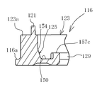
- Each corner portion 125 has a tapered surface 154 in which the lower side of the inner peripheral surface of the circular portion 123a forms a downward slope toward the bottom of the annular groove 150 (see FIG. 27).
- the tapered surface 154 corresponds to the tapered surface 135a (FIG. 22) of the corner portion 135 provided on the thick outer peripheral portion 132 of the elastic body 130, and forms a high seal structure that is in close contact during assembly.
- the slopes of both tapered surfaces 154 and 135a can be the same or different.
- the tapered surface 154 in the corner portion 125 is steeper, and the corner portion 135 of the elastic body 130 is assembled during assembly. Can be tightly fitted onto the corner portion 125 of the lower frame member 116 so that the tapered surfaces 135a and 154 can be brought into close contact with each other.
- each positioning pin 121 is inserted into the positioning hole 121a of the upper frame member 115, and when the tip of each positioning pin 121 is crimped while pressing the upper frame member 115 against the elastic body 130 with a predetermined pressure, the partition member 106 is integrated. Can be assembled.
- the elastic body 130 has the two-sided width portion 136 at the outer periphery thereof in contact with the two-sided width portion 126 of the annular partition wall 123 as shown in FIG.
- the relief holes 119 and 129 and the relief valve 133 can be accurately and reliably and easily aligned.
- the relief passage 139 can be maintained constant and the relief valve 133 can be accurately opened and closed.
- the tapered surface 135a is provided at the corner portion 135 of the thick outer peripheral portion 132, a high seal structure can be obtained by assembling the taper surface 135a to the tapered surface 154 of the corner portion 125 by taper alignment.
- the relief valve 133 is positioned inside each of the circular portions 123a and 123b of the annular partition wall 123, and as shown in FIG. Adhere closely to the liquid. As a result, the relief passage 139 is closed, and the flow of hydraulic fluid from the sub liquid chamber 107 side to the main liquid chamber 105 side through the relief passage 139 is prevented (the same applies to the circular portion 123a side).
- FIG. 28 illustrates the operation of the relief valve 133
- (a) and (b) are enlarged views of a cross-sectional portion corresponding to FIG. (A) shows a state in which a large input is entered with the relief valve 133 closed, and the inclined surface 141 receives a hydraulic pressure F1 due to the large input by being greatly bent downward and bulging.
- the seal portion 142 slides on the inner peripheral surface of the annular partition wall 123 to maintain close contact, and does not relieve the hydraulic fluid from the lower auxiliary liquid chamber 107 side to the main liquid chamber 105 side.
- (B) shows a state in which, after a large input, the vibration direction is reversed, the volume of the main liquid chamber 105 becomes the expansion direction, and the main liquid chamber becomes negative pressure.
- the inclined surface 141 is sucked to the main liquid chamber 105 side, and at the same time, the working liquid on the auxiliary liquid chamber 107 side pushes up the inclined surface 141 of the relief valve 133 from below, so that the relief valve 133 is deformed to be turned from the tip side.
- the seal portion 142 is opened away from the inner peripheral surface of the annular partition wall 123, and the working fluid flows from the auxiliary liquid chamber 107 ⁇ the relief hole 129 ⁇ the relief passage 139 and the relief hole 119 ⁇ the main liquid chamber 105 to the main liquid. Since the fluid pressure in the chamber 105 is increased, the occurrence of the cavitation phenomenon can be prevented.
- the inclined surface 141 of the relief valve 133 is inclined at the tip side toward the main liquid chamber 105, so that the hydraulic fluid is concentrated on the tip-side seal portion 142 by being guided by the inclined surface 141. Therefore, the relief valve 133 opens smoothly when the main liquid chamber 105 reaches a predetermined negative pressure.
- FIG. 28C is an enlarged cross-sectional view of the intermediate support portion 152 in order to explain the operation of the intermediate support portion 152, and shows a state in which an excessive hydraulic pressure F2 is applied from the main liquid chamber 105.
- the tapered surface 153 of the intermediate support portion 152 supports the lower portion of the inclined surface 141 at the intermediate portion in the length direction of the relief valve 133. Therefore, by supporting the intermediate portion in the length direction where the deformation becomes largest, excessive deformation of the inclined surface 141 can be prevented, and leakage due to excessive deformation can be prevented to prevent a decrease in damping force. For this reason, a predetermined relief flow rate can be secured when the cavitation phenomenon occurs at the time of large input, and the occurrence of the cavitation phenomenon can be reliably prevented.
- the amount of relief at the time of opening the valve can be increased and the hydraulic pressure can be adjusted quickly. Therefore, only one relief valve 133 can be provided. Further, by supporting the intermediate portion in the length direction of the relief valve 133 by the intermediate support portion 152, it is possible to substantially use such a large relief valve 133. Further, while increasing the opening area of the relief holes 119 and 129 in order to secure a large relief amount, the strength of the lower frame member 116 is ensured by providing the intermediate support portion 152 in the relief hole 129 that is opened in this way. Thus, it is possible to use the lower frame member 116 having such a large opening area.
- the relief valve 133 is lengthened to about 1/3 of the large-diameter assumed circle C1, it is possible to increase the flow rate of the hydraulic fluid during relief and efficiently suppress the occurrence of the cavitation phenomenon.
- the number of relief valves 133 can be reduced by half, and as fixed portions at both ends in the length direction of the relief valves 133 By increasing the volume of the thick outer peripheral portion 132, the support rigidity can be increased, and liquid leakage can be prevented.
- the most difficult part of the relief valve 133 to bend is the connection part with the corner part 135 at the end in the length direction.
- the number of such difficult parts can be halved.
- the operability of the relief valve 133 can be relatively improved.
- the thick outer peripheral portion 132 between the relief valves 133 can be secured relatively long (in this embodiment, the opening angle is approximately 60 °). A considerable width is secured).
- a portion sandwiched between the pair of opposing relief valves 133 in the outer peripheral thick wall portion 132 can be secured as a sufficiently large empty space (a space where the relief valve 133 is not formed).
- the enlarged portion 137 can be formed on the inner portion thereof.
- the movable film part 131 can be made into a non-circular large-sized structure and the pressure receiving area can be expanded, the spring of the movable film part 131 is lowered to reduce the dynamic spring even though the relief valve 133 is provided on the outer peripheral part.
- the orifice passage 108 can be arranged closer to the outer peripheral side. For this reason, the diameter of the inner peripheral surface of the annular partition wall 123 can be increased to enlarge the fitting space 127, and the elastic body 130 fitted therein can be enlarged. As a result, the relief valve 133 provided on the elastic body 130 can be increased in size, and the cut two-surface width portion 136 that forms the enlarged portion 137 can be secured to a sufficient size.
- the part which provided the enlarged part 137 among the thick outer peripheral parts 132 is made into the two-surface width part 136, and this two-surface width part 136 is wide in the two-surface width part 126 formed in the internal peripheral surface of the annular partition wall 123.
- the working fluid flows from the main fluid chamber 105 to the sub fluid chamber 107 in the direction indicated by the arrow A in FIG. 15 through the recess 122 forming the orifice passage 108, so that the working fluid flows into the main fluid chamber 105.
- the anti-rotation portion has an outer periphery of the thick outer peripheral portion 132 between the left and right relief valves 133 regardless of the width of the two surfaces.
- a non-circular portion having a polygonal shape can also exhibit a detent function.
- FIG. 29 is an example in which such a two-sided width is not provided, and the two-sided width portion 136 as in FIG. 15 is not provided, and instead, a part of the thick outer peripheral portion 132 in which the enlarged portion 137 is provided. Is formed by continuously providing an arcuate enlarged portion 132b having an arcuate outer circumference along the assumed large diameter circle C1 to the valve portion 132a. If it does in this way, the expansion part 137 can be expanded further to an outer peripheral side, and can be made low spring. Further, if the enlarged portion 137 is not enlarged, the support rigidity of the arcuate enlarged portion 132b can be increased, and the operations of the relief valve 133 and the movable film portion 131 can be stabilized. Furthermore, the liquid seal vibration isolator of the present invention is not limited to the engine mount, and various powertrain mounts can be applied.
Landscapes
- Engineering & Computer Science (AREA)
- General Engineering & Computer Science (AREA)
- Mechanical Engineering (AREA)
- Combined Devices Of Dampers And Springs (AREA)
- Arrangement Or Mounting Of Propulsion Units For Vehicles (AREA)
Abstract
Description
また、仕切部材を金属等の枠部材とこれに嵌合支持される弾性体で構成し、この弾性体の中央部を薄肉円形の可動膜として主液室の液圧変動を吸収させるとともに、この弾性体の外周部を厚肉に形成し、この外周部にリリーフバルブを一体に形成したものもある。
この場合、弾性体にはオリフィス通路へ渦巻いて流入する作動液により回転方向(図10中のA矢示方向)へ力を受け、弾性体が枠部材に対して回転すると、リリーフバルブがリリーフ通路とずれて開閉が不正確になり、キャビテーション現象の発生阻止が不確実になることがあるため、弾性体の外周部に厚肉の突出部を設け、これを枠部材に固定して回り止めとしたものも公知である(特許文献1参照)。
また、この場合、リリーフバルブは周方向へ等間隔で設けられ、それぞれの周方向長さ(周長)が、中心からの開き角で略60°、全周の略1/6程度に形成されている。
また、大入力時には弾性体が回転等してリリーフ通路に対してずれると、リリーフ通路を狭めてリリーフ時における副液室から主液室へ向かう作動液のリリーフ流量を減少させ、その結果、主液室内の負圧レベルを低減(負圧を正圧側へ戻すこと)しにくくなって、キャビテーション現象の発生を確実には阻止できなくなることがあった。組立時においてリリーフバルブの位置がずれても同様のことになった。
さらに、リリーフバルブが大入力時に弾性変形したとき、一部が局部的な変形でシール性を低下させ、ここから液漏れすることにより減衰力が低下することも考えられる。
しかも、リリーフバルブを大きくした場合は、リリーフバルブ自体が大入力時に大きく弾性変形して主液室の液圧を必要以上に下げることにより減衰力を低下させることも考えられる。
そこで本願発明は、弾性体を用いた仕切部材において、弾性体を確実に回り止め可能にして正確に位置決めすることでキャビテーション現象の発生を確実に阻止できるようにすることを目的とし、併せて高減衰を実現できるようにすることも目的とする。
また、この種の液封防振装置においては、ゴムバネである可動膜により主液室の液圧変動を吸収し易くして低動バネにすることで、振動の伝達量を低減することも求められている。
しかし、可動膜は外周部のリリーフバルブに囲まれてその内側に形成されるため比較的小面積である程度高いバネにならざるを得ない。
一方、低動バネ化を実現するための一つの方法として、可動膜のバネを低くすることが考えられ、このためには、可動膜の主液室に臨む受圧面積を拡大するか膜厚を薄くすることが考えられる。
しかし、可動膜の面積は、防振装置全体をコンパクトにする基本的な要請のうえで外周部にリリーフバルブを形成する必要から比較的狭いものとされ、可動膜の面積を自由に拡大することができない。
そのうえ、可動膜の膜厚にも所定の限界があり、無制限に薄くすることは減衰力の大幅な低下を招くため、やはり自ずから限界がある。
その結果、外周部にリリーフバルブを設けた形式の防振装置においては、可動膜を低バネにして低動バネを実現することが難しい実情にあった。
そこで、本願は外周部にリリーフバルブを有する可動膜を用いた仕切部材において、リリーフバルブの開閉時における抵抗部位の数を削減してよりスムーズな開閉を実現すると同時に、装置全体の外周サイズを拡大させることなく可動膜の受圧面積を拡大して低バネにすることで低動バネを実現させることをもう一つの目的とする。
前記リリーフバルブは、前記弾性体の中心を挟んで対向配置された一対だけであり、
前記厚肉外周部のうち前記一対のリリーフバルブ間部分の外周を非円形形状の回り止め部にするとともに、
この回り止め部に対応する嵌合部を前記枠部材に設け、
前記弾性体を前記枠部材に嵌合し、前記回り止め部と前記嵌合部とを嵌合させた。
弾性体の厚肉外周部のうち一対のリリーフバルブ間における部分全体を平面視非円形状に形成して回り止め部とし、この回り止め部に対応する嵌合部が設けられている枠部材に弾性体を嵌合させることで、一対のリリーフバルブ間における厚肉外周部全体をリリーフバルブの支持固定部としたので、リリーフバルブの支持固定部を高い支持剛性のあるものにできる。
このため、枠部材に対して弾性体を正確に位置決めして、リリーフ通路を一定に維持できるので、大入力時においてキャビテーション現象の発生条件となったときに所定のリリーフ流量を確保でき、キャビテーション現象の発生を確実に阻止できるようになる。
しかも、装置全体の外径寸法を拡大せずにコンパクト化が可能であり、かつ低動バネ化のために可動膜を不必要に薄くしないで済むため所定の減衰及び耐久性を維持できる。
したがって、リリーフバルブをスムーズに開閉可能になるとともに、低動バネを同時に実現できるようになった。
このエンジンマウントは、振動源であるエンジン(図示省略)側へ取付けられる第1取付部材1と、振動受側である車体(同上)へ取付けられる第2取付部材2と、これらの間を連結するインシュレータ3とを備える。インシュレータ3は、ゴム等の公知の防振用弾性部材で構成され、振動に対する防振主体部材となる弾性体であり、主たる振動の入力方向Zより第1取付部材1へ入力した振動はまずインシュレータ3の弾性変形により吸収される。主たる振動の入力方向Zは、図示の中心線CLと平行である。なお、以下の説明において、図の上方からZ方向に沿って示す図を平面図(平面視図)ということにする。
主液室5は、仕切部材6により副液室7と区画され、オリフィス通路8により仕切部材6を隔てて副液室7と連通されている。副液室7は、ダイヤフラム10と仕切部材6の間に形成され、ダイヤフラム10を壁部の一部としている。
オリフィス通路8は、例えば、10~11Hz程度のシェイク振動等からなる低周波数の振動に対して共振するよう設定されている減衰オリフィスである。
上下を反転させた状態において、仕切部材6は、外筒金具11の上方から内側へ入れて段差14にて位置決めし、続いてダイヤフラム10の固定用リング38を外筒金具11の内側に挿入した状態で仕切部材6の上面へ当接し、外筒金具11を絞り加工し、さらに外筒金具11の先端である下端部11aを内側へ折り曲げて折り曲げ部11bとして、固定用リング38を圧接するカシメにより、全体が組立一体化される。
図2は枠部材16の平面図、図3は図2の3-3断面図、図4は弾性体の平面図、図5は図4の5-5断面図、図6は図4の6-6断面図、図7は図4の7-7断面図、図8は仕切部材の分解組立斜視図、図9は組立状態にある仕切部材の断面図(図1と同じ断面部位)、図10は弾性体を枠部材へ嵌合し、蓋部材を取付ける前の状態における平面図、図11は図10の11-11断面図、図12及び図13は作用説明のための断面図である。
なお、図13は図10の13-13断面に相当する部位を示す。
蓋部材15は中央に中央上開口18が設けられ、その外周側に円弧状のリリーフ穴19が左右一対で設けられている。20はオリフィス通路の主液室側出入口である。
なお、図2中のA矢示方向は円弧状溝22にて主液室5から副液室7への作動液の流れる方向を示す。
円弧状溝22は、その内周壁をなす環状隔壁23で枠部材16の内周側部分と区画され、この環状隔壁23の内側は弾性体30が嵌合されるための嵌合空間をなす。
この嵌合空間の底部中央には中央下開口28が設けられ、その外周側に円弧状のリリーフ穴29が左右一対で設けられている。
この厚肉外周部32には略V字溝状のリリーフバルブ33が形成されている。リリーフバルブ33は円弧状をなして周方向へ長く(略1/4周程度)形成され、弾性体30の中心を挟んで180°間隔で対向配置され、一対だけで設けられている。
図7に示すように、環状隔壁23と弾性体30(リリーフバルブ33)の間にはリリーフ穴19及び29を連通するリリーフ通路39が形成される。リリーフバルブ33はこのリリーフ通路39を開閉し、通常時は閉じており、大入力時において主液室5が所定の負圧になるときのみ開き、副液室7側から主液室5側へ作動液をリリーフさせるようになっている。なお、円弧状溝22の長さ方向他端は枠部材16に設けられた副液室側出入口49(図2参照)が臨む。
まず、図8及び図9等により蓋部材15を説明する。蓋部材15は平面視が円形で剛性を有する軽金属や硬質樹脂等の適宜材料で構成される略円板状の部材である。
蓋部材15の中央部は一段低くなった中央段部17をなし、ここに主液室5に連通する中央上開口18が形成され、十文字状の変形規制枠18aで区画されている。変形規制枠18aは可動膜部31の過大弾性変形時にその上面側に当接支持して過大弾性変形を規制する。中央段部17の外周側には、約90°の円弧状の長穴をなす一対のリリーフ穴19が略1/4周程度の長さで同一円周上に180°間隔で蓋部材15の中心を挟んで対向配置されている。
弾性体との嵌合空間の底部中央には副液室7と連通する中央下開口28が形成されている。28aは副液室側の変形規制枠であり、可動膜部31の過大弾性変形時にその下面側を当接支持して過大弾性変形を規制する。
環状ストッパ部25bは下部32aの内周側における位置決めをなし、可動膜部31の弾性変形により厚肉外周部32が径方向内方へ引っ張られたとき、下部32aが径方向内方へ引っ張り出されないように固定する。
図8中の符号21は、3本の位置決めピンであり、環状隔壁23の周囲上面から突設し、蓋部材15に形成された位置決め穴21aに挿通して先端をカシメることにより、図11に示すように、蓋部材15と枠部材16が位置決めされて一体化され、蓋部材15と枠部材16が相対回転不能になる。
図4及び図8に示すように、弾性体30はゴム等の弾性に富む適宜弾性材料からなり、枠部材16の嵌合空間へ嵌合可能な形状及び寸法をなす。すなわち、環状隔壁23の内周と略同径の外周部が内接する想定円(図4中に仮想線で示す)の対向位置を平行に切り取った弦に相当する二面幅部46a、46bが一対で形成され、この一対の二面幅部40a、40b間の外周部32には一対のリリーフバルブ33が対向配置されている。
図3・5・8等に示すように、コーナー部45は枠部材16のコーナー部51へ重なる部分であり、外壁面がテーパー面44をなし、コーナー部51のテーパー面50に対応する傾斜と形状及び寸法を有している。コーナー部51及び二面幅部46a、46bは本願発明における嵌合部をなしている。
なお、コーナー部45を含めて厚肉の二面幅部46a、46bが対向する一対のリリーフバルブ33の各長さ方向端部間を連結することにより、一対のリリーフバルブ33間に挟まれた部分全体が、外周長の略1/4に相当する程度の十分に長い厚肉部でリリーフバルブ33の各長さ方向端部間を支持するので、リリーフバルブ33に対する支持剛性を十分に高くすることができるとともに、確実な回り止め機能を発揮できる。
このため、組立時においてテーパー合わせで仕切部材6を容易に組立てることができ、枠部材16に対して弾性体30を正確に位置決めして、リリーフ通路29を一定に維持できる。また、その後の使用時においても確実な回り止めによりリリーフ通路29を一定に維持できるので、大入力時においてキャビテーション現象の発生条件となったときに所定のリリーフ流量を確保でき、キャビテーション現象の発生を確実に阻止できるようになる。
また、各コーナー部45及び51のテーパー面44及び50をテーパー合わせによって、各コーナー部のシール性を高めることができるので、大入力時に弾性体外周部へ大きな力が加わっても、両コーナー部45及び51間のテーパー合わせ部における弾性体外周部と枠部材の間は高液密状態を維持して、この部分からの液漏れを防ぐことができるため減衰力低下を阻止することができる。
しかも、テーパー合わせ部における高いシール性が得られるので、弾性変形させる力を受けやすいリリーフバルブ33近傍のコーナー部45であっても、コーナー部51とのテーパー合わせ部により液漏れを防止できる。
なお、このような液漏れを防ぐため、図4に示すように、弾性体30の表面には複数のシール57a~57dが形成されている。
そのうえ、図10に示すように、高剛性の支持部である二面幅部46a、46bの各平面状をなす外側面が、同じく平面状をなす環状隔壁23の内周面に形成された二面幅部46a、46bに広い面積で当接するので、弾性体30はその外周部における二面幅部40a、40bを利用して大入力時であっても確実な回り止めが可能になる。
図6・7に示すように、リリーフバルブ33は、厚肉外周部32の一部へ一体的に形成された凹部35を有し、この凹部35を囲む径方向外方の壁部が副液室7側から主液室5側へ向かって斜め上がりに外方へ開くように設けられた斜面34をなし、この斜面の先端部が厚肉で外表面側が環状隔壁23の内周面へ液密に密着するシール部36をなす。
しかも、大きなリリーフ量を確保するためリリーフ穴19・29の開口面積を増加させ、リリーフバルブ33を長くしても、その過大変形を容易かつ確実に阻止できる。また、過大変形による不必要な主液室5の液圧吸収が生じないため、この点でも減衰力の低下を阻止することができる。
このエンジンマウントは、振動源であるエンジン(図示省略)側へ取付けられる第1取付部材101と、振動受側である車体(同上)へ取付けられる第2取付部材102と、これらの間を連結するインシュレータ103とを備える。インシュレータ103は、ゴム等の公知の防振用弾性部材で構成され、振動に対する防振主体部材となる弾性体であり、主たる振動の入力方向Zより第1取付部材101へ入力した振動はまずインシュレータ103の弾性変形により吸収される。主たる振動の入力方向Zは、図示の中心線CLと平行である。なお、以下の説明において、図の上方からZ方向に沿って示す図を平面図(平面視図)ということにする。
主液室105は、仕切部材106により副液室107と区画され、オリフィス通路108により仕切部材106を隔てて副液室107と連通されている。副液室107は、ダイヤフラム110と仕切部材106の間に形成され、ダイヤフラム110を壁部の一部としている。
オリフィス通路108は、例えば、10~11Hz程度のシェイク振動等からなる低周波数の振動に対して共振するよう設定されている減衰オリフィスである。
まず、仕切部材106の構成を主として図17に基づいて概略説明する。仕切部材106は、上下に分離される上枠部材115と下枠部材116とで弾性体130を中央部に挟持した3部材から構成される。
なお、図15中のA矢示方向は凹部122にて主液室105から副液室107への作動液の流れる方向を示す。
この嵌合空間127の底部中央には中央下開口128が設けられ、その外周側に円弧状のリリーフ穴129が左右一対で設けられている。
この厚肉外周部132には略V字溝状のリリーフバルブ133が形成されている。リリーフバルブ133は円弧状をなして周方向へ長く(開き角略120°、略1/3周長程度)形成され、弾性体130の中心を挟んで180°間隔で対向配置された一対で設けられている。このリリーフバルブ133は従来のように対向する一対を一組として計二組で設けられたものと異なり、一組だけで設けられている。
このとき厚肉外周部132の下部は、下枠部材116の環状溝150に嵌合して位置決めされ、さらに、上枠部材115と下枠部材116で上下から挟まれて固定される拘束部であり、可動膜部131の環状支持部をなしている。
このようにすると、オリフィス通路108はその外周壁を下枠部材116ではなく、延長部112及び外筒金具111とし、これら延長部112及び外筒金具111をオリフィス通路108の構成材料に利用することができるので、オリフィス通路108の外壁を下枠部材116に設けなくても済むことになり、それだけオリフィス通路108を外周側へ寄せて配置できる。
これらの図において、上枠部材115は平面視が円形で剛性を有する軽金属や硬質樹脂等の適宜材料で構成される略円板状の部材である。
図20~23に示すように、弾性体130はゴム等の弾性に富む適宜弾性材料からなり、下枠部材116の嵌合空間127(図17)へ嵌合可能な形状及び寸法をなす。
バルブ部132aの長さ方向両端にはコーナー部135が計4個設けられ、各コーナー部135は中心Oを挟んで対向配置されている。
すなわち、図20に示すように、大径想定円C1及び小径想定円C2の各半径をR1、R2とし、二面幅部136の中点Mにおける半径(Mと弾性体130の中心との距離)を半径R4とすれば、図21に示すように、切り欠き部134の形成により、R4がR1よりもΔRだけ短くなっている。R3は想定円C3の半径である。
小突起131bは一つの同心円上に等間隔で配設され、この同心円状の列が径方向へ複数列(本例では6列)設けられている。この小突起131bは可動膜部131が弾性変形するとき、上下の変形規制枠118a(図18)、128a(図24)に対して小さな接触面積で初期接触して打音を軽減するようになっている。
図24は下枠部材116の平面図、図25は図24の25-25線断面図、図26は図24の26-26線断面図、図27は図24の27-27線断面図である。
図24に示すように、下枠部材116は外周の平面視が円形であり、剛性を有する軽金属や硬質樹脂等の適宜材料で構成される。外周の内側には環状隔壁123が設けられ、この環状隔壁123の内側に非円形の環状溝150を挟んで、同じく非円形の中央段部157が設けられている。
二面幅部126は部分的に平面状をなし、弾性体130を環状隔壁123の内側へ嵌合したとき、その二面幅部136が密に重なるようになっている。
環状溝150の溝幅は周方向で変化し、環状隔壁123の円形部123a及び123bと中央段部157の小径部157bとの間隔は広く、二面幅部126と拡大部157cの間隔は狭くなっている。
リリーフ穴129は円形部123a及び123bにおける両端のコーナー部125間に形成される平面視で円弧状の長穴であり、長手方向中間部に径方向へ横切る中間支持部152が形成されている。
続いて、各位置決めピン121を上枠部材115の位置決め穴121aへ挿通し、上枠部材115を所定圧で弾性体130へ押しつけながら各位置決めピン121の先端をカシメれば、仕切部材106が一体化して組立てられる。
また、厚肉外周部132のコーナー部135にテーパー面135aを設けてあるので、これをコーナー部125のテーパー面154へテーパー合わせで密着させることで組立により高シール構造を得ることができる。
図28は、リリーフバルブ133の動作を説明し、(a)(b)は図16に相当する断面部位の拡大図である。(a)はリリーフバルブ133が閉じた状態で大入力が入った状態を示し、斜面141は下方へ大きく撓んで膨出変形することにより大入力による液圧F1を受け止める。このときシール部142は環状隔壁123の内周面上を摺動して密着を維持し、下方の副液室107側から作動液を主液室105側へリリーフさせない。
このため、大入力時においてキャビテーション現象の発生条件となったときに所定のリリーフ流量を確保して、キャビテーション現象の発生を確実に阻止できるようになる。
さらに、大きなリリーフ量を確保するためリリーフ穴119・129の開口面積を増加させつつも、このように大きく開口されたリリーフ穴129に中間支持部152を設けることにより下枠部材116の強度を確保して、このような大きな開口面積を有する下枠部材116の使用を可能にする。
さらに、本願発明の液封防振装置は、エンジンマウントに限らず、種々なパワートレイン用マウントが適用可能である。
Claims (9)
- 液室を主液室と副液室に区画するとともにこれらを連通するオリフィス通路を設けた仕切部材を、弾性体とこの弾性体を嵌合支持する枠部材とを備えたものとし、弾性体の中央部を薄肉の可動膜としこの可動膜周囲をリング状の厚肉外周部とし、この厚肉外周部にリリーフバルブを一体に形成した液封防振装置において、
前記リリーフバルブは、前記弾性体の中心を挟んで対向配置された一対だけであり、
前記厚肉外周部のうち前記一対のリリーフバルブ間部分の外周を非円形形状の回り止め部にするとともに、
この回り止め部に対応する嵌合部を前記枠部材に設け、
前記弾性体を前記枠部材に嵌合し、前記回り止め部と前記嵌合部とを嵌合させたことを特徴とする液封防振装置。 - 前記可動膜の一部を、前記一対のリリーフバルブ間に位置する前記厚肉外周部内へ入り込むようにし、前記可動膜を非円形形状にしたことを特徴とする請求項1に記載の液封防振装置。
- 前記回り止め部は、前記弾性体の厚肉外周部に対して外周部の対向位置を平行する直線状に形成した2面幅形状としたことを特徴とする請求項1に記載した液封防振装置。
- 前記枠部材の前記リリーフバルブと対応する位置に円弧状のリリーフ穴を設けるとともに、このリリーフ穴の長さ方向中間部に前記リリーフバルブを支持する中間支持部を形成したことを特徴とする請求項1に記載した液封防振装置。
- 前記弾性体と枠部材との嵌合部のうち、前記回り止め部とその嵌合部の少なくとも一部をテーパー形状としたことを特徴とする請求項1に記載した液封防振装置。
- 前記弾性体における前記リリーフバルブの長さ方向端部に隣接する部分であるコーナー部と、このコーナー部を嵌合する前記枠部材側に設けられたコーナー部とをそれぞれ前記テーパー形状にしたことを特徴とする請求項1に記載した液封防振装置。
- 前記枠部材に、前記リリーフバルブの前記副液室側部分を支持する中間支持部を形成したことを特徴とする請求項1に記載した液封防振装置。
- 前記枠部材には前記オリフィス通路を構成する凹部を外側方が開放された状態で形成されるとともに、この凹部の外側方を閉じて前記オリフィス通路の外周部を閉じる部材とし、前記液室及び仕切部材の各外側を覆う部材としたことを特徴とする請求項1に記載した液封防振装置。
- 前記リリーフバルブは一つの想定円に沿う円弧状をなして前記弾性体の周方向へ、前記想定円の周長の略1/3程度の長さに形成されることを特徴とする請求項1に記載した液封防振装置。
Priority Applications (4)
| Application Number | Priority Date | Filing Date | Title |
|---|---|---|---|
| DE112011100692T DE112011100692T5 (de) | 2010-02-25 | 2011-02-23 | Flüssigkeitsdichte Schwingungsisolationsvorrichtung |
| US13/578,647 US8876093B2 (en) | 2010-02-25 | 2011-02-23 | Liquid sealed vibration isolating device |
| JP2012501807A JP5380603B2 (ja) | 2010-02-25 | 2011-02-23 | 液封防振装置 |
| CN201180010863.1A CN102770686B (zh) | 2010-02-25 | 2011-02-23 | 液体密封防振装置 |
Applications Claiming Priority (4)
| Application Number | Priority Date | Filing Date | Title |
|---|---|---|---|
| JP2010040902 | 2010-02-25 | ||
| JP2010-040902 | 2010-02-25 | ||
| JP2010095511 | 2010-04-16 | ||
| JP2010-095511 | 2010-04-16 |
Publications (1)
| Publication Number | Publication Date |
|---|---|
| WO2011105404A1 true WO2011105404A1 (ja) | 2011-09-01 |
Family
ID=44506809
Family Applications (1)
| Application Number | Title | Priority Date | Filing Date |
|---|---|---|---|
| PCT/JP2011/053921 Ceased WO2011105404A1 (ja) | 2010-02-25 | 2011-02-23 | 液封防振装置 |
Country Status (5)
| Country | Link |
|---|---|
| US (1) | US8876093B2 (ja) |
| JP (1) | JP5380603B2 (ja) |
| CN (1) | CN102770686B (ja) |
| DE (1) | DE112011100692T5 (ja) |
| WO (1) | WO2011105404A1 (ja) |
Cited By (8)
| Publication number | Priority date | Publication date | Assignee | Title |
|---|---|---|---|---|
| WO2014098148A1 (ja) * | 2012-12-20 | 2014-06-26 | 山下ゴム株式会社 | 液封防振装置 |
| WO2014098147A1 (ja) * | 2012-12-20 | 2014-06-26 | 山下ゴム株式会社 | 液封防振装置 |
| JP2014122685A (ja) * | 2012-12-21 | 2014-07-03 | Yamashita Rubber Co Ltd | 液封防振装置 |
| JP2014219035A (ja) * | 2013-05-07 | 2014-11-20 | 東海ゴム工業株式会社 | 流体封入式防振装置 |
| WO2015064196A1 (ja) * | 2013-10-31 | 2015-05-07 | 株式会社東郷製作所 | 液体封入式防振装置用オリフィス部材とそのオリフィス部材を備えた液体封入式防振装置 |
| WO2015159976A1 (ja) * | 2014-04-18 | 2015-10-22 | 山下ゴム株式会社 | 液封防振装置 |
| CN107076251A (zh) * | 2014-10-06 | 2017-08-18 | 山下橡胶株式会社 | 防振装置 |
| CN108454373A (zh) * | 2018-04-20 | 2018-08-28 | 东风商用车有限公司 | 一种v型悬置总成结构 |
Families Citing this family (21)
| Publication number | Priority date | Publication date | Assignee | Title |
|---|---|---|---|---|
| WO2014025255A1 (en) | 2012-08-06 | 2014-02-13 | Wellinq Medical B.V. | Pressure sensor catheter and associated method |
| JP6028099B2 (ja) * | 2013-06-03 | 2016-11-16 | 株式会社ブリヂストン | 防振装置 |
| KR101510350B1 (ko) * | 2013-08-28 | 2015-04-07 | 현대자동차 주식회사 | 진동을 흡수하는 마운팅 장치 |
| CN103758917B (zh) * | 2013-12-30 | 2016-02-03 | 长城汽车股份有限公司 | 发动机液压悬置及具有该发动机液压悬置的车辆 |
| DE102014202999A1 (de) * | 2014-02-19 | 2015-08-20 | Boge Elastmetall Gmbh | Düsenplatte für ein axial dämpfendes Hydrolager |
| DE102014108840B4 (de) * | 2014-06-24 | 2019-05-09 | Vibracoustic Gmbh | Entkoppeltes Hydrolager |
| CN104290583B (zh) * | 2014-09-28 | 2017-10-20 | 长城汽车股份有限公司 | 悬置装置 |
| CN104806688A (zh) * | 2015-04-29 | 2015-07-29 | 安徽江淮汽车股份有限公司 | 一种液压悬置 |
| US10589615B2 (en) * | 2015-08-03 | 2020-03-17 | Ford Global Technologies, Llc | Decoupler for a hydraulic engine mount |
| DE102016206948A1 (de) * | 2016-04-25 | 2017-10-26 | Contitech Vibration Control Gmbh | Hydrolager, insbesondere steuerbares Hydrolager |
| US10190651B2 (en) * | 2016-06-16 | 2019-01-29 | Beijingwest Industries Co., Ltd. | Multi-stage damping assembly |
| CN107143596B (zh) * | 2016-06-16 | 2019-07-26 | 北京京西重工有限公司 | 用于多级阻尼的组件 |
| US11448286B2 (en) * | 2017-04-27 | 2022-09-20 | Prospira Corporation | Vibration-damping device |
| KR102453592B1 (ko) * | 2017-08-21 | 2022-10-11 | 현대자동차주식회사 | Tm마운트의 스토퍼 |
| KR102451984B1 (ko) * | 2017-10-31 | 2022-10-06 | 현대자동차주식회사 | 자동차용 유체 봉입형 마운트 |
| JP7346189B2 (ja) * | 2019-09-17 | 2023-09-19 | 株式会社プロスパイラ | 防振装置 |
| CN110686037B (zh) * | 2019-10-24 | 2024-06-07 | 中国人民解放军陆军工程大学 | 一种高承载力圆柱弹簧橡胶组合式隔震器 |
| KR102869284B1 (ko) * | 2020-04-01 | 2025-10-10 | 현대자동차주식회사 | 자동차용 엔진마운트 |
| CN113404804A (zh) * | 2021-06-15 | 2021-09-17 | 中国第一汽车股份有限公司 | 一种液压悬置装置及车辆 |
| CN113494557B (zh) * | 2021-07-27 | 2022-07-05 | 重庆长安汽车股份有限公司 | 一种解耦膜、悬置总成及车辆 |
| JP7742798B2 (ja) * | 2022-03-23 | 2025-09-22 | 住友理工株式会社 | 流体封入式防振装置 |
Citations (2)
| Publication number | Priority date | Publication date | Assignee | Title |
|---|---|---|---|---|
| JP2008202765A (ja) * | 2007-02-22 | 2008-09-04 | Toyo Tire & Rubber Co Ltd | 液封入式防振装置 |
| JP2009002420A (ja) * | 2007-06-20 | 2009-01-08 | Yamashita Rubber Co Ltd | 液封防振装置 |
Family Cites Families (9)
| Publication number | Priority date | Publication date | Assignee | Title |
|---|---|---|---|---|
| JP2005048906A (ja) * | 2003-07-30 | 2005-02-24 | Tokai Rubber Ind Ltd | 液体封入式防振装置 |
| US20060022110A1 (en) * | 2004-03-31 | 2006-02-02 | Tokyo Tire & Rubber Co., Ltd., | Hydraulic antivibration device and elastic partition membrane and sandwiching members for use in the same |
| CN1583443A (zh) * | 2004-05-21 | 2005-02-23 | 浙江大学 | 汽车发动机用电流变液减振器 |
| JP3943116B2 (ja) * | 2004-10-12 | 2007-07-11 | 東洋ゴム工業株式会社 | 液封入式防振装置 |
| US7328888B2 (en) * | 2004-11-24 | 2008-02-12 | Toyo Tire & Rubber Co., Ltd. | Hydraulic antivibration device and hydraulic antivibration assembly containing the same |
| JP4919783B2 (ja) * | 2006-12-05 | 2012-04-18 | 山下ゴム株式会社 | 液封防振装置 |
| WO2008069131A1 (ja) * | 2006-12-05 | 2008-06-12 | Honda Motor Co., Ltd. | 液封防振装置 |
| JP5170809B2 (ja) * | 2007-08-27 | 2013-03-27 | 山下ゴム株式会社 | 液封防振装置 |
| US8651467B2 (en) * | 2010-08-31 | 2014-02-18 | Tokai Rubber Industries, Ltd. | Fluid-filled type vibration damping device |
-
2011
- 2011-02-23 CN CN201180010863.1A patent/CN102770686B/zh active Active
- 2011-02-23 DE DE112011100692T patent/DE112011100692T5/de not_active Withdrawn
- 2011-02-23 JP JP2012501807A patent/JP5380603B2/ja active Active
- 2011-02-23 US US13/578,647 patent/US8876093B2/en active Active
- 2011-02-23 WO PCT/JP2011/053921 patent/WO2011105404A1/ja not_active Ceased
Patent Citations (2)
| Publication number | Priority date | Publication date | Assignee | Title |
|---|---|---|---|---|
| JP2008202765A (ja) * | 2007-02-22 | 2008-09-04 | Toyo Tire & Rubber Co Ltd | 液封入式防振装置 |
| JP2009002420A (ja) * | 2007-06-20 | 2009-01-08 | Yamashita Rubber Co Ltd | 液封防振装置 |
Cited By (16)
| Publication number | Priority date | Publication date | Assignee | Title |
|---|---|---|---|---|
| CN104870856B (zh) * | 2012-12-20 | 2017-03-22 | 山下橡胶株式会社 | 液封防振装置 |
| WO2014098147A1 (ja) * | 2012-12-20 | 2014-06-26 | 山下ゴム株式会社 | 液封防振装置 |
| JP2014122665A (ja) * | 2012-12-20 | 2014-07-03 | Yamashita Rubber Co Ltd | 液封防振装置 |
| JP2014122666A (ja) * | 2012-12-20 | 2014-07-03 | Yamashita Rubber Co Ltd | 液封防振装置 |
| CN104870856A (zh) * | 2012-12-20 | 2015-08-26 | 山下橡胶株式会社 | 液封防振装置 |
| WO2014098148A1 (ja) * | 2012-12-20 | 2014-06-26 | 山下ゴム株式会社 | 液封防振装置 |
| JP2014122685A (ja) * | 2012-12-21 | 2014-07-03 | Yamashita Rubber Co Ltd | 液封防振装置 |
| JP2014219035A (ja) * | 2013-05-07 | 2014-11-20 | 東海ゴム工業株式会社 | 流体封入式防振装置 |
| WO2015064196A1 (ja) * | 2013-10-31 | 2015-05-07 | 株式会社東郷製作所 | 液体封入式防振装置用オリフィス部材とそのオリフィス部材を備えた液体封入式防振装置 |
| WO2015159976A1 (ja) * | 2014-04-18 | 2015-10-22 | 山下ゴム株式会社 | 液封防振装置 |
| JP2015206401A (ja) * | 2014-04-18 | 2015-11-19 | 山下ゴム株式会社 | 液封防振装置 |
| US9958024B2 (en) | 2014-04-18 | 2018-05-01 | Yamashita Rubber Kabushiki Kaisha | Liquid sealed vibration isolating device |
| CN107076251A (zh) * | 2014-10-06 | 2017-08-18 | 山下橡胶株式会社 | 防振装置 |
| CN107076251B (zh) * | 2014-10-06 | 2019-04-30 | 山下橡胶株式会社 | 防振装置 |
| CN108454373A (zh) * | 2018-04-20 | 2018-08-28 | 东风商用车有限公司 | 一种v型悬置总成结构 |
| CN108454373B (zh) * | 2018-04-20 | 2023-10-31 | 东风商用车有限公司 | 一种v型悬置总成结构 |
Also Published As
| Publication number | Publication date |
|---|---|
| DE112011100692T5 (de) | 2013-01-17 |
| US8876093B2 (en) | 2014-11-04 |
| JPWO2011105404A1 (ja) | 2013-06-20 |
| US20120299229A1 (en) | 2012-11-29 |
| CN102770686A (zh) | 2012-11-07 |
| JP5380603B2 (ja) | 2014-01-08 |
| CN102770686B (zh) | 2015-07-22 |
Similar Documents
| Publication | Publication Date | Title |
|---|---|---|
| JP5380603B2 (ja) | 液封防振装置 | |
| CN104870856B (zh) | 液封防振装置 | |
| JP6306412B2 (ja) | 液封防振装置 | |
| JP4919783B2 (ja) | 液封防振装置 | |
| CN101784815B (zh) | 液封防振装置 | |
| JP4275791B2 (ja) | 液封マウント | |
| JP5919129B2 (ja) | 防振装置 | |
| CN104854366B (zh) | 液封隔振装置 | |
| US20060006592A1 (en) | Fluid-filled vibration damping bushing | |
| CN114728573B (zh) | 隔振装置 | |
| CN114630975B (zh) | 隔振装置 | |
| CN114641628B (zh) | 隔振装置 | |
| US20050035508A1 (en) | Fluid-filled vibration damping device | |
| JP7326122B2 (ja) | 防振装置 | |
| JP7350628B2 (ja) | 防振装置 | |
| WO2014021110A1 (ja) | 防振装置 | |
| JPH0454099B2 (ja) | ||
| JP6978982B2 (ja) | 防振装置 | |
| WO2022138029A1 (ja) | 流体封入式防振装置 | |
| JP4315556B2 (ja) | 液封防振装置 | |
| WO2016063627A1 (ja) | 防振装置 | |
| JP2023095246A (ja) | 液封入式防振装置 | |
| JP2022063558A (ja) | 防振装置 | |
| JPH04302731A (ja) | 液体封入型防振装置 | |
| JPH11210809A (ja) | 液体封入式防振装置 |
Legal Events
| Date | Code | Title | Description |
|---|---|---|---|
| WWE | Wipo information: entry into national phase |
Ref document number: 201180010863.1 Country of ref document: CN |
|
| 121 | Ep: the epo has been informed by wipo that ep was designated in this application |
Ref document number: 11747364 Country of ref document: EP Kind code of ref document: A1 |
|
| WWE | Wipo information: entry into national phase |
Ref document number: 13578647 Country of ref document: US |
|
| WWE | Wipo information: entry into national phase |
Ref document number: 2012501807 Country of ref document: JP |
|
| WWE | Wipo information: entry into national phase |
Ref document number: 1201004307 Country of ref document: TH |
|
| WWE | Wipo information: entry into national phase |
Ref document number: 112011100692 Country of ref document: DE Ref document number: 1120111006926 Country of ref document: DE |
|
| 122 | Ep: pct application non-entry in european phase |
Ref document number: 11747364 Country of ref document: EP Kind code of ref document: A1 |