WO2011105355A1 - 回転電気機械のトルクリプル抑制制御装置および制御方法 - Google Patents
回転電気機械のトルクリプル抑制制御装置および制御方法 Download PDFInfo
- Publication number
- WO2011105355A1 WO2011105355A1 PCT/JP2011/053798 JP2011053798W WO2011105355A1 WO 2011105355 A1 WO2011105355 A1 WO 2011105355A1 JP 2011053798 W JP2011053798 W JP 2011053798W WO 2011105355 A1 WO2011105355 A1 WO 2011105355A1
- Authority
- WO
- WIPO (PCT)
- Prior art keywords
- torque ripple
- torque
- coefficient
- periodic disturbance
- current
- Prior art date
- Legal status (The legal status is an assumption and is not a legal conclusion. Google has not performed a legal analysis and makes no representation as to the accuracy of the status listed.)
- Ceased
Links
Images


Classifications
-
- H—ELECTRICITY
- H02—GENERATION; CONVERSION OR DISTRIBUTION OF ELECTRIC POWER
- H02P—CONTROL OR REGULATION OF ELECTRIC MOTORS, ELECTRIC GENERATORS OR DYNAMO-ELECTRIC CONVERTERS; CONTROLLING TRANSFORMERS, REACTORS OR CHOKE COILS
- H02P21/00—Arrangements or methods for the control of electric machines by vector control, e.g. by control of field orientation
-
- H—ELECTRICITY
- H02—GENERATION; CONVERSION OR DISTRIBUTION OF ELECTRIC POWER
- H02P—CONTROL OR REGULATION OF ELECTRIC MOTORS, ELECTRIC GENERATORS OR DYNAMO-ELECTRIC CONVERTERS; CONTROLLING TRANSFORMERS, REACTORS OR CHOKE COILS
- H02P21/00—Arrangements or methods for the control of electric machines by vector control, e.g. by control of field orientation
- H02P21/05—Arrangements or methods for the control of electric machines by vector control, e.g. by control of field orientation specially adapted for damping motor oscillations, e.g. for reducing hunting
-
- H—ELECTRICITY
- H02—GENERATION; CONVERSION OR DISTRIBUTION OF ELECTRIC POWER
- H02P—CONTROL OR REGULATION OF ELECTRIC MOTORS, ELECTRIC GENERATORS OR DYNAMO-ELECTRIC CONVERTERS; CONTROLLING TRANSFORMERS, REACTORS OR CHOKE COILS
- H02P21/00—Arrangements or methods for the control of electric machines by vector control, e.g. by control of field orientation
- H02P21/13—Observer control, e.g. using Luenberger observers or Kalman filters
-
- H—ELECTRICITY
- H02—GENERATION; CONVERSION OR DISTRIBUTION OF ELECTRIC POWER
- H02P—CONTROL OR REGULATION OF ELECTRIC MOTORS, ELECTRIC GENERATORS OR DYNAMO-ELECTRIC CONVERTERS; CONTROLLING TRANSFORMERS, REACTORS OR CHOKE COILS
- H02P23/00—Arrangements or methods for the control of AC motors characterised by a control method other than vector control
- H02P23/04—Arrangements or methods for the control of AC motors characterised by a control method other than vector control specially adapted for damping motor oscillations, e.g. for reducing hunting
-
- H—ELECTRICITY
- H02—GENERATION; CONVERSION OR DISTRIBUTION OF ELECTRIC POWER
- H02P—CONTROL OR REGULATION OF ELECTRIC MOTORS, ELECTRIC GENERATORS OR DYNAMO-ELECTRIC CONVERTERS; CONTROLLING TRANSFORMERS, REACTORS OR CHOKE COILS
- H02P27/00—Arrangements or methods for the control of AC motors characterised by the kind of supply voltage
- H02P27/04—Arrangements or methods for the control of AC motors characterised by the kind of supply voltage using variable-frequency supply voltage, e.g. inverter or converter supply voltage
Definitions
- the present invention relates to a control device and a control method for automatically suppressing torque ripple (torque pulsation) of a rotating electric machine in a torque control device of a rotating electric machine such as a motor, and more particularly to periodic disturbance suppression control by a periodic disturbance observer.
- torque ripple torque pulsation
- the motor in principle generates torque ripple (torque pulsation), causing various problems such as vibration, noise, adverse effects on riding comfort, and electrical / mechanical resonance.
- torque ripple torque pulsation
- IPMSM embedded magnet PM motor
- Non-Patent Document 1 The inventors of the present application have already proposed a feedback suppression control method using an axial torque meter for the purpose of highly accurately suppressing torque ripple, which is a cause of electrical / mechanical resonance, in response to the above problems (for example, Non-Patent Document 1). reference).
- This control method focuses on the periodicity of torque ripple and constructs a control system that compensates for each pulsation frequency component, and also has a function that automatically adjusts parameters to respond quickly to changes in the operating state using the system identification result. The details of this control method will be described below.
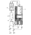
- FIG. 2 is a basic configuration diagram of a conventional torque ripple suppression control device. This figure is applied to a system in which a load is driven by a motor.
- a motor 1 that is a torque ripple generation source and some load device 2 are coupled by a shaft 3, and its shaft torque is measured by a torque meter 4 and input to a torque ripple suppression device 5. Moreover, the rotor position (phase) information of a motor is input using rotational position sensors 6, such as a rotary encoder.
- the torque ripple suppression device 5 includes torque pulsation suppression means, and gives the inverter 7 a command value obtained by adding a torque pulsation compensation current to the current command value generated based on the torque command value (or speed command value). In the example of FIG.
- torque ripple torque pulsation
- means for extracting a torque ripple frequency component in synchronism with the motor rotation is used to convert the torque ripple of arbitrary order n into cosine and sine coefficients T An and T Bn [Nm].
- the exact measurement means for torque ripple frequency components includes Fourier transform, but if importance is placed on the ease of operation, a low-pass filter can be passed through a single-phase harmonic rotation coordinate system based on the rotation phase ⁇ [rad]. A torque ripple frequency component can be extracted.
- the torque ripple suppression device 5 performs torque ripple suppression control using the cosine and sine coefficients T An and T Bn described above, and the cosine / sine coefficients I An and I Bn [ampere] of the compensation current iqc * [ampere] of an arbitrary frequency component. Is generated. Conversion to the compensation current iqc * is obtained by the following equation (2) using the same rotation phase ⁇ as that at the time of conversion, and this compensation current is superposed on the q-axis current command value and normal vector control is performed.
- FIG. 3 shows the cosine and sine coefficients T An and T Bn of the torque ripple obtained from the detected shaft torque value T det and the rotational phase ⁇ , and the compensation current cosine coefficient I An and sine coefficient I Bn obtained from these and the rotational speed ⁇ .
- FIG. 5 is a control block diagram of a torque ripple suppressing device for obtaining a compensation current for torque periodic external suppression. The symbols in the figure have the following meanings.
- T * torque command value
- T det shaft torque detection value
- T An nth order torque pulsation extraction component (cosine coefficient)
- T Bn nth order torque pulsation extraction component (sine coefficient)
- ⁇ rotation speed detection value
- ⁇ rotational phase detection value
- iqc * torque ripple compensation current
- id d-axis current detection value
- id * d-axis current command value
- iq q-axis current detection value
- iq * q-axis current command value
- n n-order compensation current cosine coefficient
- l Bn n-order compensation current sine coefficient
- abz rotation sensor signal . Note that the subscript n is an nth-order component torque ripple.
- the command value conversion unit 11 converts the torque command value T * into the d-axis and q-axis current command values Id * and Iqo * of the rotation dq coordinate system in vector control.
- Current vector control unit 12 suppresses the torque ripple those superimposed torque pulsation compensation current iqc * the q-axis current command value Iqo * as q-axis current command value iq *.
- the compensation current i qc is superimposed on the q-axis current command value, but it may be applied to the d-axis current or both the d-axis and the q-axis.
- a torque pulsation compensation signal may be directly superimposed on the torque command value.
- the current vector control unit 12 performs a current vector control operation on a general orthogonal rotating coordinate system d-axis and q-axis, and drives the motor (IPMSM) 13 by vector control to drive the load device 14.
- the coordinate conversion unit 15 converts the three-phase alternating currents iu, iv, iw detected by the current sensor 16 and the motor rotation phase ⁇ into currents id, iq in a dq axis orthogonal rotation coordinate system synchronized with the motor rotation coordinates.
- the rotation phase / speed detection unit 17 converts the rotation sensor signal abz of the rotation position sensor 18 such as an encoder into information on the rotation speed ⁇ and the rotation phase ⁇ .
- the torque pulsation frequency component extraction unit 19 extracts torque periodic disturbance for each pulsation frequency component from the shaft torque detection value T det detected by the shaft torque meter 20 and the rotation phase ⁇ .
- a typical extraction means is Fourier transform. The method of extracting the pulsation component is arbitrary, but the emphasis is placed on ease of calculation, and the shaft torque detection value T det [Nm] is multiplied by the nth-order cosine wave and sine wave based on the rotational phase ⁇ , and each is passed through a low-frequency range. By applying a filter, an approximate Fourier transform shown in equations (3) to (5) is performed. This is called torque ripple synchronous coordinate transformation.
- the torque ripple suppression control unit 21 performs torque ripple suppression control with each order component using T An and T Bn extracted and converted by the equations (3) to (5), and the nth order frequency of the compensation current i qc * [A].
- a cosine coefficient I An * [A] and a sine coefficient I Bn * [A] of the component i qcn * [A] are generated.
- the conversion to the n-th order compensation current i qcn * is calculated using the same rotation phase ⁇ as in the torque ripple synchronous coordinate conversion, as in the equation (2).
- the torque command T * [Nm] is converted into dq-axis current command values i d * and i q0 * that realize the maximum torque / current control, and the combined value i qc * of each compensation current generated by the equation (2) . Is superposed on i q0 * to perform vector control.
- the contents of calculation processing performed by the torque ripple suppression control device are extraction of shaft torque pulsation component, torque ripple suppression, and compensation current signal generation, and other processing is performed by a general inverter.
- a periodic disturbance observer compensation method or a compensation current Fourier coefficient learning control method can be used.
- the compensation current generator 22 generates a compensation current command value iqc * by the above equation (2) and superimposes it on the q-axis current command value.
- the system configuration shown in FIG. 2 is a multi-inertia torsional resonance system due to the moment of inertia of the PM motor 1, the load device 2, the torque meter 4, the coupling 3, and the like.
- the suppression control parameter must be appropriately determined according to the operation state. If the learning time of the control parameter is long, there is a risk of increasing the electric / mechanical resonance phenomenon, so a quick automatic adjustment function is necessary.
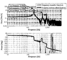
- Non-Patent Document 1 in order to derive a variable nominal control parameter adapted to a change in rotational speed, the system transfer function from the output value to the input value of the torque ripple suppression device 5 in FIG. 2, that is, the compensation current command in FIG.
- the frequency transfer function from the value iqc * to the detected value T det of the shaft torque detector 4 is identified.
- the system identification method is arbitrary, but the shaft torque detection value T det when a Gaussian noise signal is given to iqc * in an open loop is measured for 20 seconds at a calculation period of 100 ⁇ s, and the frequency is calculated from the ratio of input and output power spectral densities.
- the results of non-parametric estimation of the transfer function are shown in Fig.
- a system identification table can be constructed from 1000 complex vector elements. Only one complex vector is always used in the control system, and P Am and P Bm are instantaneously read from the identification table according to changes in the rotational speed (torque ripple frequency change), and converted into complex vectors by linear interpolation. The identified results are applied to suppression control.
- corresponds to a real part component
- a sine coefficient corresponds to an imaginary part component.
- the compensation current coefficient is obtained by the IP (proportional / integral) learning control method.
- the proportional / integral gain is determined by the model matching method so that the closed loop characteristic of the IP suppression control system matches the pole arrangement of an arbitrary standard system reference model.
- the parameters are automatically adapted using the system identification result and the rotation speed information, the implementation to the multi-inertia resonance system is facilitated.
- the periodic disturbance observer compensation method of the present method directly estimates the torque ripple disturbance using the concept of the periodic disturbance observer, and thus can improve the above responsiveness problem. Therefore, torque ripple can always be suppressed by online feedback even for a system having variable speed and load fluctuation.
- the system identification result expressed by a one-dimensional complex vector is used to provide a function for automatically adjusting the inverse model of the periodic disturbance observer. It has a feature that makes it easy to implement.
- FIG. 5 is a calculation block diagram of torque ripple suppression control by a periodic disturbance observer, wherein 31 is a periodic disturbance observer unit, 32 is a torque ripple extracting unit, and 33 is an actual system.
- dI An * n-th order periodic disturbance current real part (cosine coefficient) command value
- dI Bn * n-th order periodic disturbance current imaginary part (sine coefficient) command value
- iqcn n-order compensation current
- dI An Real part (cosine) component estimated value of nth order periodic disturbance
- dI Bn Imaginary part (sine) component estimated value of nth order periodic disturbance
- I An Real part of nth order compensation current (cosine coefficient)
- I Bn n-order compensation current imaginary part (sine coefficient).
- P An System real part of n-th order torque ripple frequency component
- P Bn System imaginary part of n-th order torque ripple frequency component
- P ⁇ An System real part estimated value of n-th order torque ripple frequency component
- P ⁇ Bn n-th order torque ripple frequency System imaginary part estimate of component
- FIG. 5 shows the same configuration as that of a general conventional disturbance observer.
- the system characteristic is expressed by a one-dimensional complex vector as shown in equation (7).
- the inverse system P ⁇ sys -1 can be simply indicated by the reciprocal of the equation (8) using the system identification result.
- the periodic disturbance observer estimates the real part component and the imaginary part component of the periodic disturbance (torque ripple) through the observer filter after performing the above complex vector calculation.
- the periodic disturbance estimated value real part dI An and imaginary part dI Bn may be given as compensation currents so as to cancel the disturbance components as shown in FIG. Normally, by setting the periodic disturbance current command values I An * and I Bn * to zero (0), the disturbance current of the frequency component can be suppressed.
- the feedback control response decreases due to the effect of computation dead time in the high frequency band, and disturbance suppression performance in the high frequency band decreases, It becomes difficult to generate a desired compensation current.
- the periodic learning method obtained by the above-described IP (proportional / integral) learning control method generates a sine wave / cosine wave having the same frequency as that of the periodic disturbance and then generates the sine / cosine coefficient (amplitude (Equivalent to phase). Therefore, this method is easier to deal with high frequency disturbances than a controller that collectively generates compensation currents in all frequency bands, and can be expected to improve periodic disturbance suppression performance.
- a torque ripple suppression controller is configured in parallel for each target order, it is possible to simultaneously cope with torque ripple suppression of a plurality of orders.
- Non-Patent Document 1 in order to construct a control system with torque ripple synchronous coordinates, only the frequency transfer function of an arbitrary n-th order component is extracted from Expression (12), and the actual system of torque ripple synchronous coordinates is represented by Expression (13). That is, it is noted that the amplitude / phase characteristics of an arbitrary n-order component system can be expressed by a simple one-dimensional complex vector P n . Similar to equations (2) to (5), the real part / imaginary part axes are defined with reference to the rotational phase ⁇ , the cosine coefficient corresponds to the real part component, and the sine coefficient corresponds to the imaginary part component.
- P An Real system n-order component real part
- P Bn Real system n-order component imaginary part
- the system identification result in the control system of FIG. 3 can also be defined as a formula (14) with a one-dimensional complex vector.
- the system identification result of 1 to 1000 Hz is expressed as a complex vector for each IHz
- a table composed of 1000 one-dimensional complex vector elements can be constructed. It is also possible to express the identification result by an approximate expression.
- the purpose of the present invention is to suppress the periodic ripple by the periodic disturbance observer, and to suppress the torque ripple of a rotating electric machine that can suppress the torque ripple with high accuracy in response to complex electromechanical characteristics such as multi-inertia system and inverter response.
- a control device and a control method are provided.
- the periodic disturbance observer calculates the system transfer function for each n-th order torque ripple frequency component from the torque command value to the torque detection value by the real part P ⁇ An and the imaginary part P ⁇ Bn .
- the cosine coefficient T An the sine coefficient T Bn , the real part P ⁇ An and the imaginary part P ⁇ Bn of the system transfer function
- the real part I ⁇ of the current estimation value including the periodic disturbance seeking an and imaginary part I ⁇ Bn
- compensation current command value through a pulsation extraction filter G F from each of the real part I ⁇ an and the imaginary part I ⁇ Bn current estimated value I an *, subtracted I Bn *
- An estimated value of the periodic disturbance current real part dI ⁇ An and imaginary part dI ⁇ Bn for canceling the periodic disturbance current is obtained.
- the following apparatus and method are characterized.
- the torque command value or speed command value of the rotating electrical machine system is converted into the d and q-axis current command values of the rotating coordinate system in vector control, and the frequency characteristics of the rotating electrical machine control system are set to an arbitrary frequency by system identification.
- the model is expressed by a complex vector of components, and using this model, the real and imaginary parts of the torque ripple of an arbitrary frequency component are estimated by a periodic disturbance observer, and the above d, q so as to suppress this periodic disturbance.
- a torque ripple suppression control device for a rotating electrical machine that superimposes a feedback compensation current on a shaft current command value, Torque ripple seeking shaft torque detection value T det pulsating extraction filter G F and the rotational phase cosine coefficients of n order frequency components different torque pulsation torque ripple of the rotary electric machine system has a theta T An sine coefficient T Bn rotary electric machine An extractor; A periodic disturbance observer for estimating the n-th compensation current cosine coefficient I ⁇ An and the sine coefficient I ⁇ Bn of the torque ripple from the cosine coefficient T An and the sine coefficient T Bn and the rotational speed ⁇ of the rotating electrical machine; The cosine coefficient I ⁇ An and the sine coefficient I ⁇ Bn are set as torque ripple compensation current command values, and the periodic disturbance suppression of the rotating electrical machine system is determined from the cosine coefficient I ⁇ An , the sine coefficient I ⁇ Bn, and the rotational phase ⁇ of the rotating electrical machine.
- a compensation current generator for obtaining a feedback compensation current of The periodic disturbance observer is A value that identifies the transfer function of a rotating electromechanical system for each n-th order torque ripple frequency component from the torque command value to the detected torque value as a one-dimensional complex vector of n-order component real part P ⁇ An and n-order component imaginary part P ⁇ Bn Means to estimate From the cosine coefficient T An and sine coefficient T Bn, the n-order component real part P ⁇ An and the n-order component imaginary part P ⁇ Bn ,
- Means for obtaining a real part I ⁇ An and an imaginary part I ⁇ Bn of an estimated current value including a periodic disturbance by calculating From each of the real part I ⁇ An and the imaginary part I ⁇ Bn of the current estimated value, the pulsating extraction filter G compensation current command value via the F I An *, subtracted I Bn *, to counteract the periodic disturbance current Means for obtaining an estimate of the real part dI ⁇ An and the imaginary part dI ⁇ Bn of the periodic disturbance current of It is provided with.
- the pulsating extraction filter G F is characterized in that the first-order low-pass filter or high-order low-pass filter.
- the torque command value or speed command value of the rotating electrical machine system is converted into the d and q axis current command values of the rotating coordinate system in vector control, and the frequency characteristics of the rotating electrical machine control system are set to an arbitrary frequency by system identification.
- Rotating electric power that performs modeling expressed by a complex vector of components estimates a periodic disturbance using this model, and superimposes a feedback compensation current on the d and q-axis current command values so as to suppress the periodic disturbance
- the periodic disturbance observer estimates the n-th compensation current cosine coefficient I ⁇ An and the sine coefficient I ⁇ Bn of the torque ripple from the cosine coefficient T An and the sine coefficient T Bn and the rotational
- the periodic disturbance observer is A value that identifies the transfer function of a rotating electromechanical system for each n-th order torque ripple frequency component from the torque command value to the detected torque value as a one-dimensional complex vector of n-order component real part P ⁇ An and n-order component imaginary part P ⁇ Bn Is estimated, From the cosine coefficient T An and sine coefficient T Bn, the n-order component real part P ⁇ An and the n-order component imaginary part P ⁇ Bn ,
- the pulsating extraction filter G compensation current command value via the F I An *, subtracted I Bn *, to counteract the periodic disturbance current From each of the real part I ⁇ An and the imaginary part I ⁇ Bn of the current estimated value, the pulsating extraction filter G compensation current command value via the F I An *, subtracted I Bn *, to counteract the periodic disturbance current.
- the estimated values of the real part dI ⁇ An and the imaginary part dI ⁇ Bn are obtained.
- the periodic disturbance observer represents the system transfer function for each n-th order torque ripple frequency component from the torque command value to the torque detection value as a one-dimensional real part P ⁇ An and imaginary part P ⁇ Bn .
- the cosine coefficient T An the sine coefficient T Bn , the real part P ⁇ An and the imaginary part P ⁇ Bn of the system transfer function, the real part I ⁇ An of the current estimation value including the periodic disturbance and calculated imaginary part I ⁇ Bn, compensation current command value through a pulsation extraction filter G F from each of the real part I ⁇ an and the imaginary part I ⁇ Bn current estimated value I an *, subtracted I Bn *, periodicity
- the estimated values of the periodic disturbance current real part dI ⁇ An and imaginary part dI ⁇ Bn for canceling the disturbance current are obtained, it also supports complex electromechanical characteristics such as multi-inertia system and inverter response. Torque ripple can be suppressed with high
- the calculation block diagram of torque ripple suppression control by a periodic disturbance observer The basic block diagram of the conventional torque ripple suppression control apparatus.
- the control block diagram of the conventional torque ripple suppression apparatus System identification result by nonparametric estimation of frequency transfer function.
- the calculation block diagram of the torque ripple suppression control by the conventional periodic disturbance observer The basic block diagram of the conventional torque ripple suppression control apparatus.
- FIG. 1 is a calculation block diagram of torque ripple suppression control by a periodic disturbance observer in the present embodiment.
- the torque ripple extraction unit 32 (torque ripple pulsation frequency component extraction unit 19 in FIG. 3) performs a calculation based on the above-described equations (3) to (5) to obtain an n-th order torque pulsation extraction component (cosine coefficient) T An and n Next torque pulsation extraction component (sine coefficient) TBn is obtained.
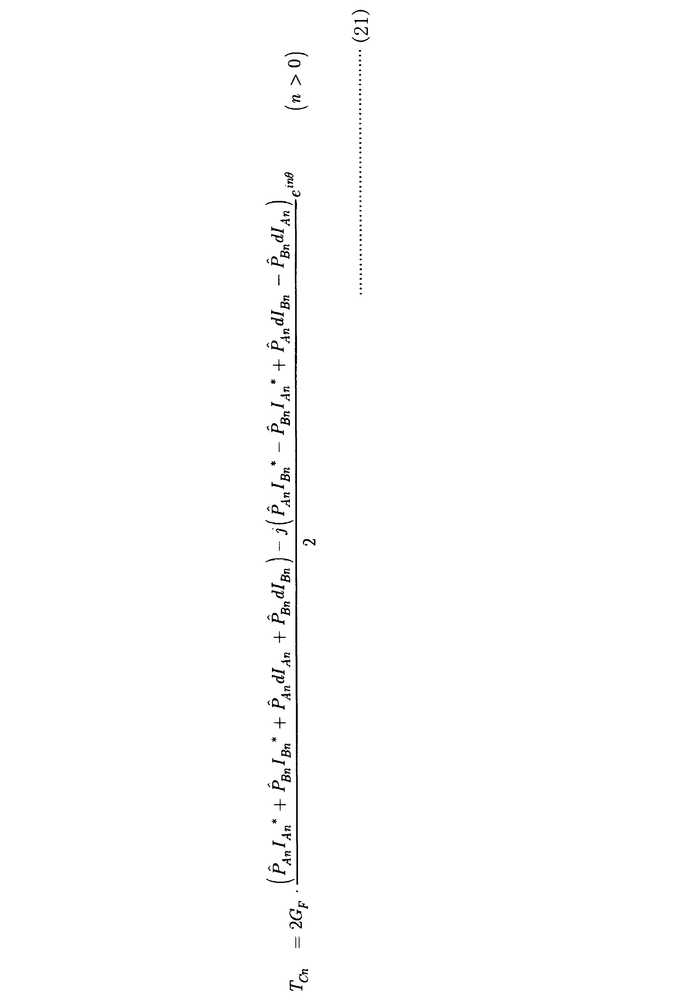
- the periodic disturbance observer 31 (torque ripple suppression control unit 21 in FIG. 3) is similar to the periodic disturbance observer proposed in Non-Patent Document 1, but is composed of torque ripple synchronous coordinates, so that the periodic disturbance current is calculated from the detected torque ripple value.
- the inverse characteristic of the one-dimensional complex vector shown in the equation (14) is used for the model of the inverse system for estimation.
- the torque ripple detection value T det of the n-th order component is expressed as follows.
- the n-th periodic disturbance current di n can be expressed as follows.
- the real part I ⁇ An ( ⁇ I An * + dI An ) and the imaginary part I ⁇ Bn ( ⁇ I Bn * + dI Bn ) of the current estimation value including the periodic disturbance are derived from the equation (22) as follows.
- the periodic disturbance current can be estimated by the above equation (24), the periodic disturbance current command value dI An * and the imaginary part dI so as to cancel the periodic disturbance current in advance as shown in FIG. 1 based on the estimated value.
- the compensation current command value real part I An * and imaginary part I Bn * are generated by subtracting from Bn * (normally 0).
- the target value response up to the torque ripple detection value of this control system can be derived as equation (25), and the periodic disturbance response can be derived as equation (26).
- pole placement is determined by the cutoff frequency omega f of the pulsation extraction filter G F, it can be seen that inhibited more, the periodic disturbance current final value theorem (26).
- the inverse model of equation (23) has a characteristic that changes adaptively to the rotational speed ⁇ (torque ripple frequency), and the control system parameters are automatically adjusted.
Landscapes
- Engineering & Computer Science (AREA)
- Power Engineering (AREA)
- Control Of Ac Motors In General (AREA)
Abstract
Description
図2は、従来のトルクリプル抑制制御装置の基本構成図である。同図は、モータによって負荷を駆動するシステムに適用したものである。

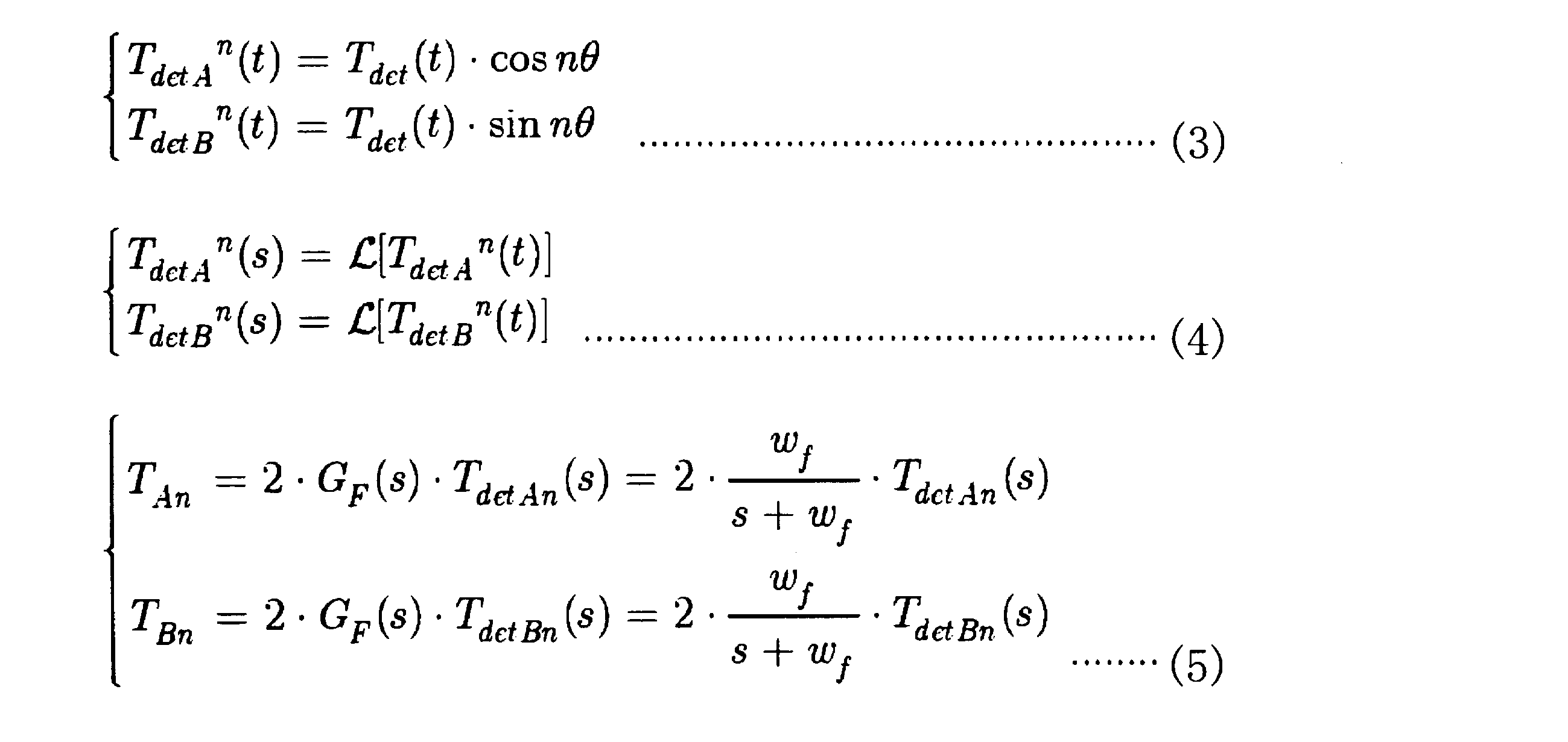
図2に示すようなシステム構成は、PMモータ1,負荷装置2,卜ルクメータ4,カップリング3等の慣性モーメントにより多慣性軸ねじれ共振系となる。軸トルク検出値をフィードバックする場合は複数の共振・反共振周波数があるため、動作状態に応じて適切に抑制制御パラメータを決定しなければならない。制御パラメータの学習時間か長いと電気・機械共振現象を増大させる危険があるため、速やかな自動調整機能が必要である。

前記の非特許文献1に方式1として記載されるトルクリプル抑制制御法であり、トルクリプル周波数成分のフーリエ係数として求め、これから前記(2)式の演算で補償電流iqc*を求める。この制御法では、トルクリプル周波数に同期した周波数成分のシステム伝達関数を1次元複素ベクトルで表現し、任意周波数成分のトルクリプルの実部・虚部をフーリエ変換等で抽出している。その余弦・正弦フーリエ係数を複素ベクトルの実部・虚部に当てはめて、フィードバック抑制制御系を構築する。
前記の非特許文献1に方式2として記載されるトルクリプル抑制制御法である。前記補償電流フーリエ係数学習制御法での制御パラメータ自動調整手法は、I-P制御ゲインの調整を介して外乱を抑制するため、可変速運転に対する即応性が低下する。そのため、学習した結果を予めテーブル化しておき、フィードフォワード抑制する使い方を推奨している。






回転電気機械の軸トルク検出値Tdetと脈動抽出フィルタGFおよび回転位相θから回転電気機械システムのトルクリプルが有するn次周波数成分別のトルク脈動の余弦係数TAnと正弦係数TBnを求めるトルクリプル抽出部と、
前記余弦係数TAnと正弦係数TBnおよび回転電気機械の回転速度ωからトルクリプルのn次補償電流余弦係数I^Anと正弦係数I^Bnを推定する周期性外乱オブザーバと、
前記余弦係数I^Anと正弦係数I^Bnをトルクリプル補償電流指令値とし、これら余弦係数I^Anと正弦係数I^Bnと回転電気機械の回転位相θから回転電気機械システムの周期性外乱抑制のフィードバック補償電流を求める補償電流生成部とを備え、
前記周期性外乱オブザーバは、
トルク指令値からトルク検出値までのn次トルクリプル周波数成分別の回転電気機械システムの伝達関数をn次成分実部P^Anとn次成分虚部P^Bnの1次元複素ベクトルで同定した値を推定しておく手段と、
前記余弦係数TAnと正弦係数TBnおよび前記n次成分実部P^Anとn次成分虚部P^Bnから、次式

前記電流推定値の実部I^Anおよび虚部I^Bnのそれぞれから、前記脈動抽出フィルタGFを介した補償電流指令値IAn *、IBn *を差し引き、周期性外乱電流を打ち消すための周期性外乱電流実部dI^Anおよび虚部dI^Bnの推定値を得る手段と、
を備えたことを特徴とする。
トルクリプル抽出部は、回転電気機械の軸トルク検出値Tdetと脈動抽出フィルタGFおよび回転位相θから回転電気機械システムのトルクリプルが有するn次周波数成分別のトルク脈動の余弦係数TAnと正弦係数TBnを求め、
周期性外乱オブザーバは、前記余弦係数TAnと正弦係数TBnおよび回転電気機械の回転速度ωからトルクリプルのn次補償電流余弦係数I^Anと正弦係数I^Bnを推定し、
補償電流生成部は、前記余弦係数I^Anと正弦係数I^Bnをトルクリプル補償電流指令値とし、これら余弦係数I^Anと正弦係数I^Bnと回転電気機械の回転位相θから回転電気機械システムの周期性外乱抑制のフィードバック補償電流を求め、
前記周期性外乱オブザーバは、
トルク指令値からトルク検出値までのn次トルクリプル周波数成分別の回転電気機械システムの伝達関数をn次成分実部P^Anとn次成分虚部P^Bnの1次元複素ベクトルで同定した値を推定しておき、
前記余弦係数TAnと正弦係数TBnおよび前記n次成分実部P^Anとn次成分虚部P^Bnから、次式

前記電流推定値の実部I^Anおよび虚部I^Bnのそれぞれから、前記脈動抽出フィルタGFを介した補償電流指令値IAn *、IBn *を差し引き、周期性外乱電流を打ち消すための周期性外乱電流実部dI^Anおよび虚部dI^Bnの推定値を得ることを特徴とする。








12 電流ベクトル制御部
13 モータ
14 負荷装置
15 座標変換部
16 電流センサ
17 回転位相/速度検出部
18 回転位置センサ
19 トルク脈動周波数成分抽出部
20 軸トルク検出器
21 トルクリプル抑制制御部
22 補償電流生成部
31 周期性外乱オブザーバ部
32 トルクリプル抽出部
33 実システム
Claims (3)
- 回転電気機械システムのトルク指令値または速度指令値をベクトル制御における回転座標系のd,q軸電流指令値に変換し、回転電気機械の制御系の周波数特性をシステムの同定によって任意周波数成分の複素ベクトルで表現したモデル化を行い、このモデルを使って任意周波数成分のトルクリプルの実部・虚部を周期性外乱オブザーバで推定し、この周期性外乱を抑圧するように前記d,q軸電流指令値にフィードバック補償電流を重畳する回転電気機械のトルクリプル抑制制御装置であって、
回転電気機械の軸トルク検出値Tdetと脈動抽出フィルタGFおよび回転位相θから回転電気機械システムのトルクリプルが有するn次周波数成分別のトルク脈動の余弦係数TAnと正弦係数TBnを求めるトルクリプル抽出部と、
前記余弦係数TAnと正弦係数TBnおよび回転電気機械の回転速度ωからトルクリプルのn次補償電流余弦係数I^Anと正弦係数I^Bnを推定する周期性外乱オブザーバと、
前記余弦係数I^Anと正弦係数I^Bnをトルクリプル補償電流指令値とし、これら余弦係数I^Anと正弦係数I^Bnと回転電気機械の回転位相θから回転電気機械システムの周期性外乱抑制のフィードバック補償電流を求める補償電流生成部とを備え、
前記周期性外乱オブザーバは、
トルク指令値からトルク検出値までのn次トルクリプル周波数成分別の回転電気機械システムの伝達関数をn次成分実部P^Anとn次成分虚部P^Bnの1次元複素ベクトルで同定した値を推定しておく手段と、
前記余弦係数TAnと正弦係数TBnおよび前記n次成分実部P^Anとn次成分虚部P^Bnから、次式
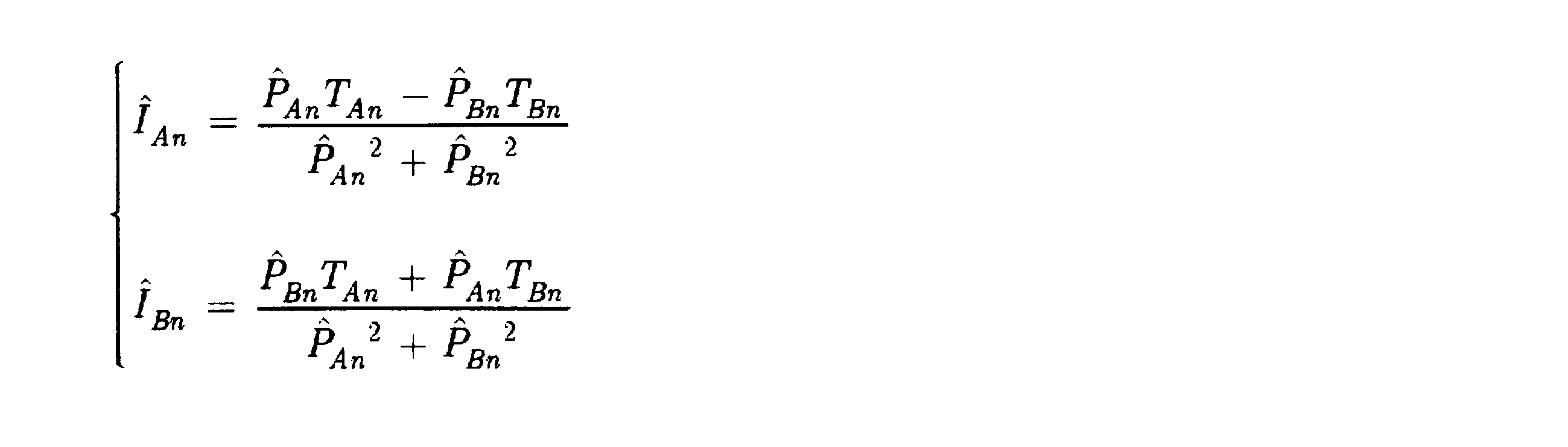
前記電流推定値の実部I^Anおよび虚部I^Bnのそれぞれから、前記脈動抽出フィルタGFを介した補償電流指令値IAn *、IBn *を差し引き、周期性外乱電流を打ち消すための周期性外乱電流実部dI^Anおよび虚部dI^Bnの推定値を得る手段と、
を備えたことを特徴とする回転電気機械のトルクリプル抑制制御装置。 - 前記脈動抽出フィルタGFは、1次ローパスフィルタまたは高次の低域通過フィルタとしたことを特徴とする請求項1に記載の回転電気機械のトルクリプル抑制制御装置。
- 回転電気機械システムのトルク指令値または速度指令値をベクトル制御における回転座標系のd,q軸電流指令値に変換し、回転電気機械の制御系の周波数特性をシステムの同定によって任意周波数成分の複素ベクトルで表現したモデル化を行い、このモデルを使って周期性外乱を推定し、この周期性外乱を抑圧するように前記d,q軸電流指令値にフィードバック補償電流を重畳する回転電気機械のトルクリプル抑制制御方法であって、
トルクリプル抽出部は、回転電気機械の軸トルク検出値Tdetと脈動抽出フィルタGFおよび回転位相θから回転電気機械システムのトルクリプルが有するn次周波数成分別のトルク脈動の余弦係数TAnと正弦係数TBnを求め、
周期性外乱オブザーバは、前記余弦係数TAnと正弦係数TBnおよび回転電気機械の回転速度ωからトルクリプルのn次補償電流余弦係数I^Anと正弦係数I^Bnを推定し、
補償電流生成部は、前記余弦係数I^Anと正弦係数I^Bnをトルクリプル補償電流指令値とし、これら余弦係数I^Anと正弦係数I^Bnと回転電気機械の回転位相θから回転電気機械システムの周期性外乱抑制のフィードバック補償電流を求め、
前記周期性外乱オブザーバは、
トルク指令値からトルク検出値までのn次トルクリプル周波数成分別の回転電気機械システムの伝達関数をn次成分実部P^Anとn次成分虚部P^Bnの1次元複素ベクトルで同定した値を推定しておき、
前記余弦係数TAnと正弦係数TBnおよび前記n次成分実部P^Anとn次成分虚部P^Bnから、次式
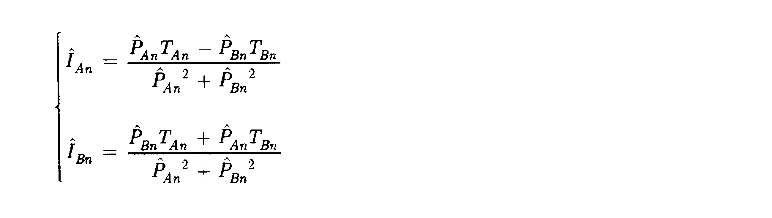
前記電流推定値の実部I^Anおよび虚部I^Bnのそれぞれから、前記脈動抽出フィルタGFを介した補償電流指令値IAn *、IBn *を差し引き、周期性外乱電流を打ち消すための周期性外乱電流実部dI^Anおよび虚部dI^Bnの推定値を得ることを特徴とする回転電気機械のトルクリプル抑制制御方法。
Priority Applications (3)
| Application Number | Priority Date | Filing Date | Title |
|---|---|---|---|
| KR1020127022750A KR101328494B1 (ko) | 2010-02-25 | 2011-02-22 | 토오크리플억제제어장치 및 회전전기기계 토오크리플억제제어방법 |
| CN201180010846.8A CN102771043B (zh) | 2010-02-25 | 2011-02-22 | 用于旋转电机的扭矩波动抑制控制装置和扭矩波动抑制控制方法 |
| US13/579,369 US8704469B2 (en) | 2010-02-25 | 2011-02-22 | Torque ripple suppression control apparatus and torque ripple suppression control method for rotating electrical machine |
Applications Claiming Priority (2)
| Application Number | Priority Date | Filing Date | Title |
|---|---|---|---|
| JP2010-039525 | 2010-02-25 | ||
| JP2010039525A JP5446988B2 (ja) | 2010-02-25 | 2010-02-25 | 回転電気機械のトルクリプル抑制制御装置および制御方法 |
Publications (1)
| Publication Number | Publication Date |
|---|---|
| WO2011105355A1 true WO2011105355A1 (ja) | 2011-09-01 |
Family
ID=44506762
Family Applications (1)
| Application Number | Title | Priority Date | Filing Date |
|---|---|---|---|
| PCT/JP2011/053798 Ceased WO2011105355A1 (ja) | 2010-02-25 | 2011-02-22 | 回転電気機械のトルクリプル抑制制御装置および制御方法 |
Country Status (5)
| Country | Link |
|---|---|
| US (1) | US8704469B2 (ja) |
| JP (1) | JP5446988B2 (ja) |
| KR (1) | KR101328494B1 (ja) |
| CN (1) | CN102771043B (ja) |
| WO (1) | WO2011105355A1 (ja) |
Cited By (7)
| Publication number | Priority date | Publication date | Assignee | Title |
|---|---|---|---|---|
| WO2013182368A3 (de) * | 2012-06-04 | 2014-07-31 | Siemens Aktiengesellschaft | Regeleinrichtung zur beseitigung von störungen im netz |
| CN104937834A (zh) * | 2013-01-31 | 2015-09-23 | Ntn株式会社 | 电动汽车用同步电动机的控制装置 |
| CN106650598A (zh) * | 2016-10-12 | 2017-05-10 | 浙江理工大学 | 一种直线电机传递函数的迭代滤波辨识方法 |
| TWI696342B (zh) * | 2019-04-09 | 2020-06-11 | 東元電機股份有限公司 | 馬達轉矩漣波補償裝置 |
| CN112491315A (zh) * | 2020-11-20 | 2021-03-12 | 西安热工研究院有限公司 | 一种抑制永磁同步电机转矩脉动的方法 |
| CN114930713A (zh) * | 2020-01-14 | 2022-08-19 | 三菱电机株式会社 | 交流电动机的驱动装置、压缩机驱动装置以及制冷循环装置 |
| CN119903800A (zh) * | 2024-12-17 | 2025-04-29 | 哈尔滨工业大学(深圳)(哈尔滨工业大学深圳科技创新研究院) | 一种高速旋转变压器复矢量解调系统设计方法、系统及应用 |
Families Citing this family (65)
| Publication number | Priority date | Publication date | Assignee | Title |
|---|---|---|---|---|
| GB2465379A (en) * | 2008-11-17 | 2010-05-19 | Technelec Ltd | Controller for electrical machines |
| JP5626090B2 (ja) * | 2011-04-15 | 2014-11-19 | 株式会社明電舎 | 周期外乱抑制装置および周期外乱抑制方法 |
| JP5895440B2 (ja) * | 2011-10-14 | 2016-03-30 | 株式会社明電舎 | 電力変換装置 |
| US8766578B2 (en) * | 2012-02-27 | 2014-07-01 | Canadian Space Agency | Method and apparatus for high velocity ripple suppression of brushless DC motors having limited drive/amplifier bandwidth |
| JP6014401B2 (ja) * | 2012-07-25 | 2016-10-25 | 東芝シュネデール・インバータ株式会社 | 電動機制御装置 |
| CN103269200B (zh) * | 2013-05-30 | 2015-05-27 | 西安空间无线电技术研究所 | 一种星载大惯量负载机构高稳速驱动控制方法 |
| CN103441715B (zh) * | 2013-08-05 | 2016-09-07 | 四川长虹电器股份有限公司 | 永磁同步电机电流补偿的控制方法 |
| FR3013535B1 (fr) * | 2013-11-15 | 2015-12-18 | Renault Sas | Procede et systeme de commande d'une machine electrique triphasee de vehicule automobile alimentee par des tensions hachees. |
| US10331094B2 (en) * | 2014-01-30 | 2019-06-25 | Meidensha Corporation | Periodic external disturbance suppression control device |
| US9160260B1 (en) * | 2014-06-16 | 2015-10-13 | Moog Inc. | Adaptive actuator control system |
| US9577561B2 (en) | 2014-07-01 | 2017-02-21 | Guangdong Meizhi Compressor Co., Ltd. | Method for suppressing a speed fluctuation, a control apparatus and a compressor control system |
| CN105450118B (zh) * | 2014-08-18 | 2019-08-16 | 珠海格力电器股份有限公司 | 电机控制方法及系统 |
| JP6398462B2 (ja) * | 2014-08-22 | 2018-10-03 | 株式会社明電舎 | 位置およびトルクセンサレスによるトルクリプル抑制装置 |
| WO2016067665A1 (ja) * | 2014-10-30 | 2016-05-06 | 三菱電機株式会社 | インバータ制御装置及びインバータ圧縮機 |
| JP6467209B2 (ja) * | 2014-12-09 | 2019-02-06 | オークマ株式会社 | 電動機のコギングトルク測定方法 |
| US10033308B2 (en) * | 2015-03-17 | 2018-07-24 | Intuitive Surgical Operations, Inc. | Systems and methods for motor torque compensation |
| CN106330042B (zh) * | 2015-07-10 | 2019-12-27 | 广州汽车集团股份有限公司 | 一种永磁同步电机谐波电流抑制方法及装置 |
| JP6157773B1 (ja) * | 2015-11-12 | 2017-07-05 | 三菱電機株式会社 | モータ制御装置およびこれを用いたエレベータ |
| JP6530696B2 (ja) * | 2015-11-25 | 2019-06-12 | オークマ株式会社 | 周波数同定器 |
| JP2017127105A (ja) * | 2016-01-13 | 2017-07-20 | 日本精工株式会社 | モータ制御装置及びそれを搭載した電動パワーステアリング装置 |
| EP3208669A1 (de) * | 2016-02-19 | 2017-08-23 | Siemens Aktiengesellschaft | Drehzahlabhängige kompensation von lagefehlern |
| JP6197923B1 (ja) * | 2016-06-27 | 2017-09-20 | 株式会社明電舎 | 制御システム |
| US9912266B2 (en) * | 2016-08-02 | 2018-03-06 | Otis Elevator Company | Motor torque ripple reduction using DC bus harmonics |
| GB201617387D0 (en) * | 2016-10-13 | 2016-11-30 | Trw Automotive Gmbh | Control system for electric motor circuit |
| JP6343037B1 (ja) * | 2017-01-11 | 2018-06-13 | 日立ジョンソンコントロールズ空調株式会社 | モータ駆動装置および冷凍機器 |
| DE102017203691A1 (de) * | 2017-03-07 | 2018-09-13 | Robert Bosch Gmbh | Regelvorrichtung für eine elektrische Maschine, elektrisches Antriebssystem und Verfahren zur Regelung einer elektrischen Maschine |
| DE102017203697A1 (de) * | 2017-03-07 | 2018-09-13 | Robert Bosch Gmbh | Verfahren zur Regelung einer elektrischen Maschine, Regelvorrichtung für eine elektrische Maschine und elektrisches Antriebssystem |
| JP6497408B2 (ja) * | 2017-04-14 | 2019-04-10 | 株式会社明電舎 | 電気慣性制御装置 |
| WO2018198694A1 (ja) * | 2017-04-27 | 2018-11-01 | 日本電産株式会社 | 電圧指令値を出力する制御装置 |
| DE102017207418A1 (de) * | 2017-05-03 | 2018-11-08 | Robert Bosch Gmbh | Geräuscharme Ansteuerung eines Elektromotors durch aktive Nenndrehzahlmodulation |
| AT520232B1 (de) * | 2017-07-21 | 2019-11-15 | Avl List Gmbh | Verfahren und Vorrichtung zum Schätzen der Drehmomentwelligkeit eines Elektromotors |
| CN109795335B (zh) * | 2017-11-16 | 2020-08-18 | 宝沃汽车(中国)有限公司 | 电动汽车的扭矩滤波方法、系统及电动汽车 |
| CN107834931B (zh) * | 2017-12-12 | 2019-11-15 | 重庆长安新能源汽车科技有限公司 | 一种电动汽车及其电机谐波抑制系统 |
| US11499537B2 (en) * | 2017-12-17 | 2022-11-15 | Microchip Technology Incorporated | Closed loop torque compensation for compressor applications |
| KR102436844B1 (ko) * | 2018-02-02 | 2022-08-26 | 주식회사 만도 | 모터의 토크 보상 장치 및 방법 |
| CN111713008B (zh) * | 2018-02-20 | 2023-09-19 | 日本电产株式会社 | 马达控制系统和助力转向系统 |
| WO2019163587A1 (ja) * | 2018-02-20 | 2019-08-29 | 日本電産株式会社 | モータ制御システム、およびパワーステアリングシステム |
| WO2020031526A1 (ja) * | 2018-08-07 | 2020-02-13 | 日本電産株式会社 | 駆動制御装置、駆動装置およびパワーステアリング装置 |
| EP3629470A1 (de) * | 2018-09-28 | 2020-04-01 | Siemens Aktiengesellschaft | Reduzieren von störgeräuschen und/oder schwingungen beim betrieb einer elektrischen maschine |
| CN109586643B (zh) * | 2018-12-13 | 2021-10-29 | 青岛海尔空调器有限总公司 | 用于单转子压缩机转速波动控制的方法 |
| EP3671372A1 (de) * | 2018-12-18 | 2020-06-24 | Siemens Aktiengesellschaft | Lagegeregelte steuerung mit kompensation von elastizitätsbedingten lagefehlern |
| DE102020201203A1 (de) * | 2020-01-31 | 2021-08-05 | Robert Bosch Gesellschaft mit beschränkter Haftung | Verfahren und Vorrichtung zur Drehzahlregelung einer elektrischen Maschine für den Antrieb eines Kompressors einer Wärmpepumpe |
| CN111464085B (zh) * | 2020-04-29 | 2022-03-29 | 华南理工大学 | 一种基于阶次提取的电机电流谐波及转矩脉动抑制方法 |
| CN114070156B (zh) * | 2020-08-04 | 2023-06-23 | 美的威灵电机技术(上海)有限公司 | 基于转速信息的电机的控制方法、电机和存储介质 |
| EP3985848A1 (de) * | 2020-10-19 | 2022-04-20 | Siemens Aktiengesellschaft | Dynamoelektrische rotatorische maschine |
| US11611305B2 (en) * | 2020-10-23 | 2023-03-21 | GM Global Technology Operations LLC | Bandwidth-partitioning harmonic regulation for improved acoustic behavior of an electric drive system |
| CN113054877B (zh) * | 2021-01-12 | 2023-09-29 | 北京控制工程研究所 | 基于特征频率观测器的永磁电机谐波扰动力矩抑制系统 |
| DE102021102266B3 (de) * | 2021-02-01 | 2022-03-31 | Dr. Ing. H.C. F. Porsche Aktiengesellschaft | Verfahren zur Geräuschreduktion einer drehstromgetriebenen elektrischen Maschine |
| CN113224990B (zh) * | 2021-04-07 | 2023-04-07 | 北京汽车股份有限公司 | 应用于新能源汽车的转矩控制优化方法与装置 |
| CN114189180B (zh) * | 2021-11-16 | 2024-03-26 | 同济大学 | 一种用于电动汽车永磁同步电机转矩脉动的抑制方法 |
| US12237668B2 (en) * | 2022-03-09 | 2025-02-25 | S&C Electric Company | Fast fault detector |
| CN114679111B (zh) * | 2022-04-07 | 2025-03-28 | 华中科技大学 | 永磁同步电机电流谐波扰动抑制方法、设备及存储介质 |
| CN114884417B (zh) * | 2022-06-02 | 2025-05-30 | 东莞理工学院 | 基于注入电压谐波及在线测量的电机转速谐波抑制方法 |
| US12203472B2 (en) | 2022-07-19 | 2025-01-21 | Haier Us Appliance Solutions, Inc. | Method for operating a compressor |
| CN115593275B (zh) * | 2022-09-20 | 2024-11-05 | 北京新能源汽车股份有限公司 | 电动汽车动力电池的加热控制方法、控制设备及电动汽车 |
| US12551060B2 (en) | 2023-02-09 | 2026-02-17 | Haier Us Appliance Solutions, Inc. | High-frequency injection for sensorless control of a BLDC stand mixer |
| US12398717B2 (en) * | 2023-02-09 | 2025-08-26 | Haier Us Appliance Solutions, Inc. | Single phase field oriented control for a linear compressor |
| US12355374B2 (en) | 2023-02-09 | 2025-07-08 | Haier Us Appliance Solutions, Inc. | Field weakening for BLDC stand mixer |
| US12341459B2 (en) | 2023-02-09 | 2025-06-24 | Haier Us Appliance Solutions, Inc. | Method for avoiding stalled motor in a stand mixer with sensorless BLDC drive |
| US12395103B2 (en) | 2023-03-21 | 2025-08-19 | Haier Us Appliance Solutions, Inc. | Standstill angle detection for salient motors |
| CN119396007B (zh) * | 2024-12-31 | 2025-06-06 | 浙江工业大学 | 一种基于高阶低通滤波器的主动抗干扰方法、系统及装置 |
| US12553432B1 (en) * | 2025-03-11 | 2026-02-17 | Haier Us Appliance Solutions, Inc. | Dynamic flux weakening for a single phase linear compressor |
| CN120433666B (zh) * | 2025-06-25 | 2025-09-26 | 广东敏卓机电股份有限公司 | 一种永磁同步电机的自抗扰控制方法及相关装置 |
| CN120508213B (zh) * | 2025-07-18 | 2025-09-23 | 嘉兴市第二医院 | 一种基于虚拟仿真的介入手术力度反馈交互系统 |
| CN121239098B (zh) * | 2025-12-03 | 2026-04-03 | 福州万德电气有限公司 | 基于机电信号分析的三相异步电机调频控制方法及系统 |
Citations (3)
| Publication number | Priority date | Publication date | Assignee | Title |
|---|---|---|---|---|
| JP2004120814A (ja) * | 2002-09-24 | 2004-04-15 | Mitsubishi Electric Corp | 電動機の制御装置、電動機装置、電動機の制御方法 |
| JP2007267466A (ja) * | 2006-03-28 | 2007-10-11 | Meidensha Corp | Ipmモータのベクトル制御装置 |
| JP2009296752A (ja) * | 2008-06-04 | 2009-12-17 | Meidensha Corp | モータのトルクリップル抑制装置 |
Family Cites Families (3)
| Publication number | Priority date | Publication date | Assignee | Title |
|---|---|---|---|---|
| JP4322254B2 (ja) * | 2003-05-30 | 2009-08-26 | 日本精工株式会社 | 電動パワーステアリング装置の制御装置 |
| WO2005055411A1 (ja) * | 2003-11-26 | 2005-06-16 | Nsk Ltd. | 電動パワーステアリング装置の制御装置 |
| JP5417195B2 (ja) * | 2010-01-19 | 2014-02-12 | 国産電機株式会社 | 永久磁石モータのトルクリプル抑制制御装置、電動パワーステアリングシステム |
-
2010
- 2010-02-25 JP JP2010039525A patent/JP5446988B2/ja active Active
-
2011
- 2011-02-22 US US13/579,369 patent/US8704469B2/en active Active
- 2011-02-22 KR KR1020127022750A patent/KR101328494B1/ko not_active Expired - Fee Related
- 2011-02-22 CN CN201180010846.8A patent/CN102771043B/zh not_active Expired - Fee Related
- 2011-02-22 WO PCT/JP2011/053798 patent/WO2011105355A1/ja not_active Ceased
Patent Citations (3)
| Publication number | Priority date | Publication date | Assignee | Title |
|---|---|---|---|---|
| JP2004120814A (ja) * | 2002-09-24 | 2004-04-15 | Mitsubishi Electric Corp | 電動機の制御装置、電動機装置、電動機の制御方法 |
| JP2007267466A (ja) * | 2006-03-28 | 2007-10-11 | Meidensha Corp | Ipmモータのベクトル制御装置 |
| JP2009296752A (ja) * | 2008-06-04 | 2009-12-17 | Meidensha Corp | モータのトルクリップル抑制装置 |
Cited By (13)
| Publication number | Priority date | Publication date | Assignee | Title |
|---|---|---|---|---|
| CN104365008A (zh) * | 2012-06-04 | 2015-02-18 | 西门子公司 | 用于排除网络中的故障的调节装置 |
| US9356544B2 (en) | 2012-06-04 | 2016-05-31 | Siemens Aktiengesellschaft | Control device for eliminating malfunctions in a network |
| RU2606210C2 (ru) * | 2012-06-04 | 2017-01-10 | Сименс Акциенгезелльшафт | Устройство регулирования для устранения помех в сети |
| CN104365008B (zh) * | 2012-06-04 | 2017-03-15 | 西门子公司 | 用于排除网络中的故障的调节装置 |
| WO2013182368A3 (de) * | 2012-06-04 | 2014-07-31 | Siemens Aktiengesellschaft | Regeleinrichtung zur beseitigung von störungen im netz |
| CN104937834B (zh) * | 2013-01-31 | 2018-03-27 | Ntn株式会社 | 电动汽车用同步电动机的控制装置 |
| CN104937834A (zh) * | 2013-01-31 | 2015-09-23 | Ntn株式会社 | 电动汽车用同步电动机的控制装置 |
| CN106650598A (zh) * | 2016-10-12 | 2017-05-10 | 浙江理工大学 | 一种直线电机传递函数的迭代滤波辨识方法 |
| CN106650598B (zh) * | 2016-10-12 | 2019-06-28 | 浙江理工大学 | 一种直线电机传递函数的迭代滤波辨识方法 |
| TWI696342B (zh) * | 2019-04-09 | 2020-06-11 | 東元電機股份有限公司 | 馬達轉矩漣波補償裝置 |
| CN114930713A (zh) * | 2020-01-14 | 2022-08-19 | 三菱电机株式会社 | 交流电动机的驱动装置、压缩机驱动装置以及制冷循环装置 |
| CN112491315A (zh) * | 2020-11-20 | 2021-03-12 | 西安热工研究院有限公司 | 一种抑制永磁同步电机转矩脉动的方法 |
| CN119903800A (zh) * | 2024-12-17 | 2025-04-29 | 哈尔滨工业大学(深圳)(哈尔滨工业大学深圳科技创新研究院) | 一种高速旋转变压器复矢量解调系统设计方法、系统及应用 |
Also Published As
| Publication number | Publication date |
|---|---|
| KR101328494B1 (ko) | 2013-11-13 |
| US8704469B2 (en) | 2014-04-22 |
| CN102771043B (zh) | 2015-04-15 |
| CN102771043A (zh) | 2012-11-07 |
| KR20120120391A (ko) | 2012-11-01 |
| JP5446988B2 (ja) | 2014-03-19 |
| JP2011176953A (ja) | 2011-09-08 |
| US20120306411A1 (en) | 2012-12-06 |
Similar Documents
| Publication | Publication Date | Title |
|---|---|---|
| JP5446988B2 (ja) | 回転電気機械のトルクリプル抑制制御装置および制御方法 | |
| JP5088414B2 (ja) | 電動機の外乱抑圧装置および外乱抑圧方法 | |
| JP5488043B2 (ja) | モータのトルク制御装置 | |
| JP5621274B2 (ja) | モータのトルク制御装置 | |
| JP5488044B2 (ja) | 回転電気機械のトルクリプル抑制制御装置および制御方法 | |
| JP5637042B2 (ja) | 電動機の脈動抑制装置および電動機の脈動抑制方法 | |
| KR101699463B1 (ko) | 제어 장치 | |
| CN105680754B (zh) | 一种永磁同步电机的直交轴电流矢量复合控制器 | |
| JP5644203B2 (ja) | 回転電気機械のトルクリプル抑制制御装置および制御方法 | |
| JP2010057217A (ja) | 電動機のトルク脈動抑制装置および抑制方法 | |
| JP5936770B2 (ja) | 回転機制御装置 | |
| JP7520747B2 (ja) | インバータ制御装置およびインバータ制御装置の製造方法 | |
| JP6740890B2 (ja) | インバータの制御方法およびインバータの制御装置 | |
| KR101638714B1 (ko) | 교류 회전기의 제어 장치 | |
| KR101485989B1 (ko) | 모터 제어 장치 | |
| CN111656676A (zh) | 用于电力转换装置的控制装置以及电动机驱动系统 | |
| CN111656674A (zh) | 用于电力转换装置的控制装置、控制方法、以及电动机驱动系统 | |
| JP4910445B2 (ja) | Ipmモータのベクトル制御装置 | |
| WO2020105204A1 (ja) | 電力変換装置 | |
| JP6183554B2 (ja) | 周期外乱自動抑制装置 | |
| WO2012026568A1 (ja) | 単相信号入力装置及び系統連系装置 | |
| KR20210137190A (ko) | 모터 구동 장치 및 그것을 사용한 공기 조화기의 실외기 |
Legal Events
| Date | Code | Title | Description |
|---|---|---|---|
| WWE | Wipo information: entry into national phase |
Ref document number: 201180010846.8 Country of ref document: CN |
|
| 121 | Ep: the epo has been informed by wipo that ep was designated in this application |
Ref document number: 11747316 Country of ref document: EP Kind code of ref document: A1 |
|
| WWE | Wipo information: entry into national phase |
Ref document number: 13579369 Country of ref document: US |
|
| WWE | Wipo information: entry into national phase |
Ref document number: 1201004306 Country of ref document: TH |
|
| NENP | Non-entry into the national phase |
Ref country code: DE |
|
| ENP | Entry into the national phase |
Ref document number: 20127022750 Country of ref document: KR Kind code of ref document: A |
|
| WWE | Wipo information: entry into national phase |
Ref document number: 2715/KOLNP/2012 Country of ref document: IN |
|
| 122 | Ep: pct application non-entry in european phase |
Ref document number: 11747316 Country of ref document: EP Kind code of ref document: A1 |