WO2011102373A1 - スタビライザ用ブシュ及び車両スタビライザ - Google Patents
スタビライザ用ブシュ及び車両スタビライザ Download PDFInfo
- Publication number
- WO2011102373A1 WO2011102373A1 PCT/JP2011/053256 JP2011053256W WO2011102373A1 WO 2011102373 A1 WO2011102373 A1 WO 2011102373A1 JP 2011053256 W JP2011053256 W JP 2011053256W WO 2011102373 A1 WO2011102373 A1 WO 2011102373A1
- Authority
- WO
- WIPO (PCT)
- Prior art keywords
- bush
- stabilizer
- bracket
- adhesive
- torsion
- Prior art date
- Legal status (The legal status is an assumption and is not a legal conclusion. Google has not performed a legal analysis and makes no representation as to the accuracy of the status listed.)
- Ceased
Links
Images













Classifications
-
- F—MECHANICAL ENGINEERING; LIGHTING; HEATING; WEAPONS; BLASTING
- F16—ENGINEERING ELEMENTS AND UNITS; GENERAL MEASURES FOR PRODUCING AND MAINTAINING EFFECTIVE FUNCTIONING OF MACHINES OR INSTALLATIONS; THERMAL INSULATION IN GENERAL
- F16F—SPRINGS; SHOCK-ABSORBERS; MEANS FOR DAMPING VIBRATION
- F16F1/00—Springs
- F16F1/02—Springs made of steel or other material having low internal friction; Wound, torsion, leaf, cup, ring or the like springs, the material of the spring not being relevant
- F16F1/14—Torsion springs consisting of bars or tubes
- F16F1/16—Attachments or mountings
-
- B—PERFORMING OPERATIONS; TRANSPORTING
- B60—VEHICLES IN GENERAL
- B60G—VEHICLE SUSPENSION ARRANGEMENTS
- B60G21/00—Interconnection systems for two or more resiliently-suspended wheels, e.g. for stabilising a vehicle body with respect to acceleration, deceleration or centrifugal forces
- B60G21/02—Interconnection systems for two or more resiliently-suspended wheels, e.g. for stabilising a vehicle body with respect to acceleration, deceleration or centrifugal forces permanently interconnected
- B60G21/04—Interconnection systems for two or more resiliently-suspended wheels, e.g. for stabilising a vehicle body with respect to acceleration, deceleration or centrifugal forces permanently interconnected mechanically
- B60G21/05—Interconnection systems for two or more resiliently-suspended wheels, e.g. for stabilising a vehicle body with respect to acceleration, deceleration or centrifugal forces permanently interconnected mechanically between wheels on the same axle but on different sides of the vehicle, i.e. the left and right wheel suspensions being interconnected
- B60G21/055—Stabiliser bars
- B60G21/0551—Mounting means therefor
-
- B—PERFORMING OPERATIONS; TRANSPORTING
- B60—VEHICLES IN GENERAL
- B60G—VEHICLE SUSPENSION ARRANGEMENTS
- B60G2204/00—Indexing codes related to suspensions per se or to auxiliary parts
- B60G2204/10—Mounting of suspension elements
- B60G2204/12—Mounting of springs or dampers
- B60G2204/122—Mounting of torsion springs
- B60G2204/1222—Middle mounts of stabiliser on vehicle body or chassis
Definitions
- the present invention relates to a stabilizer bush used for a vehicle stabilizer and a vehicle stabilizer in which the stabilizer bush is incorporated, and more particularly to a technique capable of improving the stability and controllability of the vehicle.
- the stabilizer for a vehicle incorporating the stabilizer bush has a function of connecting the stabilizer bar to the suspension system of the vehicle and stabilizing the posture of the vehicle using the torsional reaction force of the stabilizer bar.
- the ends of a U-shaped stabilizer bar are connected to the operating part of the suspension device, and the torsion part of the stabilizer bar is fixed to the vehicle body frame with the stabilizer bush (fixing member), and the torsional reaction force (See, for example, JP-A-2001-270315).
- the stabilizer bush has a shape that holds a predetermined position of the torsion part, and is fixed to the body frame side.
- the stabilizer bush is generally a sliding bush, and has a structure that moves relatively along the axial direction of the torsion portion.
- the stabilizer bush described above was attached to the stabilizer bar, there were the following problems. That is, since the stabilizer bush moves relatively along the axial direction of the torsion part, the stabilizer bush may interfere with parts other than the torsion part, and abnormal noise may occur. Further, the relative positional relationship between the stabilizer bush and the torsion portion is deviated, so that the performance as the vehicle stabilizer is unstable, which adversely affects the steering stability and the ride comfort.
- the present invention provides a stabilizer bush and a vehicle stabilizer that can improve steering stability and ride comfort and prevent abnormal noise by preventing misalignment with the stabilizer bar and intrusion of muddy water.
- the purpose is that.
- a stabilizer bush according to the present invention is a stabilizer bush attached to a vehicle stabilizer having a torsion portion extending in the vehicle width direction and arm portions extending in the vehicle front-rear direction from both ends of the torsion portion. And a bush attached to the outer periphery of the torsion part via an adhesive, and a bracket attached to the bush via an adhesive and attached to the vehicle body.
- the vehicle stabilizer of the present invention has a torsion part extending in the vehicle width direction and having an engaged part, an arm part extending in the vehicle front-rear direction from both ends of the torsion part, and an engagement part. And a stabilizer bush that is engaged with and attached to the engaged portion of the torsion portion, and the engaged portion is knurled or double-sided processed, and the stabilizer bush is connected to the torsion portion.
- a bushing attached to the outer peripheral portion via an adhesive and a bracket attached to the bush via an adhesive and attached to the vehicle body are provided.
- FIG. 1 is a perspective view showing a vehicle stabilizer and a vehicle front wheel suspension according to a first embodiment of the present invention.
- FIG. 2 is a perspective view showing a stabilizer bush to a torsion portion of a stabilizer bar incorporated in the vehicle stabilizer.
- FIG. 3 is a perspective view showing a modification of the attachment portion of the torsion part.
- FIG. 4 is a view showing a modification of the attachment site.
- FIG. 5 is a view showing a modification of the attachment site.
- FIG. 6 is a side view showing a stabilizer bush according to the second embodiment of the present invention.
- FIG. 7 is a view showing a modification of the stabilizer bush.
- FIG. 8 is a perspective view showing the stabilizer bush according to the third embodiment of the present invention with a part cut away.
- FIG. 9 is a perspective view showing a stabilizer bush according to the fourth embodiment of the present invention.
- FIG. 10 is a perspective view showing a stabilizer bush according to the fifth embodiment of the present invention.
- FIG. 11 is a side view showing the stabilizer bush.
- FIG. 12 is a perspective view showing a modification of the stabilizer bush.
- FIG. 13 is a side view showing the stabilizer bush.
- FIG. 14 is a perspective view showing a modification of the stabilizer bush.
- FIG. 15 is a side view showing the stabilizer bush.
- FIG. 16 is a front view showing a bush used for the stabilizer bush described above.
- FIG. 17 is a front view showing a bush used for the stabilizer bush described above.
- FIG. 18 is a front view showing a bush used for the stabilizer bush described above.
- FIG. 16 is a front view showing a bush used for the stabilizer bush described above.
- FIG. 19 is a front view showing a bush used for the stabilizer bush described above.
- FIG. 20 is a front view showing a bush used for the stabilizer bush described above.
- FIG. 21 is an explanatory view showing a stabilizer bush according to the sixth embodiment of the present invention.
- FIG. 22 is a front view showing a stabilizer bush according to the seventh embodiment of the present invention.
- FIG. 23 is a front view showing a modified example of the stabilizer bush.
- FIG. 24 is a perspective view showing the stabilizer bush.
- FIG. 25 is a side view showing the stabilizer bush.
- FIG. 26 is a perspective view showing a modified example of the stabilizer bush.
- FIG. 27 is a perspective view showing a modified example of the stabilizer bush.
- FIG. 28 is a perspective view showing a modification of the stabilizer bush.
- FIG. 29 is a perspective view showing a modified example of the stabilizer bush.
- FIG. 30 is a perspective view showing a modification of the stabilizer bush.
- FIG. 1 is a perspective view showing a vehicle stabilizer 10 and a vehicle front wheel suspension device K according to a first embodiment of the present invention
- FIG. 2 shows a stabilizer bar 20 incorporated in the vehicle stabilizer 10 to a torsion portion 21. It is a perspective view which shows the bush (fixing member) 30 for stabilizers.
- the vehicle stabilizer 10 includes a stabilizer bar 20 made of a hollow member or a solid member, a stabilizer bush 100 for fixing the stabilizer bar 20 to the frame portion F of the vehicle body, and a tip 23a of the stabilizer bar 20 at the suspension device K. And a stabilizer link 30 connected to the operating portion.
- the stabilizer bar 20 is positioned at both ends of the torsion part 21 passed in the vehicle body width direction, the shoulder part 22, and the shoulder part 22. It is provided and is formed in a substantially U shape.
- the stabilizer bar 20 has a function of holding the suspension device K stably by the torsional reaction force of the torsion portion 21 when the operating portion of the suspension device K moves up and down, and the arm portion 23 follows the movement.
- the attachment portion 21a corresponding to the stabilizer bush 100 of the torsion portion 21 is deformed by rolling, cutting, or the like so that the cross section is an ellipse (for example, two-side width processing).
- the stabilizer bush 100 includes a bush 110 attached to the outer peripheral portion of the torsion portion 21 via an adhesive (epoxy adhesive or post-curing adhesive), and an adhesive on the bush 110. And a bracket 120 attached to the vehicle body.
- an adhesive epoxy adhesive or post-curing adhesive
- the bush 110 is formed of a rubber material, and is provided with an inner wall surface 111 having a shape along the outer peripheral surface of the attachment portion 21a.
- the outer wall surface 112 is formed of an arc portion and a straight portion. Further, a bush split portion 113 serving as an opening is formed in the lower portion in FIG.
- the bracket 120 is formed by bending a metal plate, and is formed at a bent portion 121 having an inner wall surface 121a formed along the outer wall surface 112 of the bush 110, and at both ends of the bent portion 121. And a joining portion 122 provided for joining with F. Note that a bolt hole 122 a is formed in the joint portion 122.
- the suspension device K is, for example, a double wishbone type suspension device, and front wheels and the like (not shown) are attached to the axle portions Ka provided on the left and right.
- the stabilizer bush 100 described above is manufactured by the following process. That is, after an epoxy adhesive or a post-curing adhesive is applied to the attachment portion 21a of the torsion portion 21 of the stabilizer bar 20, the bush split portion 113 is spread and bonded to a predetermined position. An adhesive is also applied to the inner wall surface 111 of the bush 110. Thereafter, epoxy powder coating is applied to the stabilizer bar 20 to further strengthen the adhesive force.
- ⁇ Cathion coating or galvanization may be used for the surface treatment of the bracket 120 in order to ensure adhesive strength.
- the vehicle stabilizer 10 configured as described above operates as follows. That is, for example, it is assumed that a wheel on one side enters a recess and one of the suspension devices K is lowered while the vehicle is running. Then, a sandwiching angle is generated in the left and right arm portions 23 or the sandwiching angle is widened, so that the torsion portion 21 is twisted and a twisting reaction force is generated. This torsional reaction force causes the torsion part 21 to return to its original state and return the suspension device K to its original position.
- the frame part F and the bracket 120 are bolted, and the bracket 120 and the bush 110 are firmly fixed by an adhesive.
- the attachment part 21a has a flat surface formed by two-sided width processing, the adhesive force becomes stronger. Therefore, relative displacement between the frame part F and the attachment part 21a of the torsion part 21 does not occur.
- the bonding area between the bracket 120 and the bush 110 may be reduced.
- the stabilizer bush 30 by preventing misalignment with the stabilizer bar 20 and intrusion of muddy water, the steering stability and the ride comfort are improved, and the generation of abnormal noise is prevented. Can do.
- an anchor effect may be added and the adhesive force may be further improved by performing a satin treatment on either or both of the inner wall surface 111 of the bush 110 and the painted surface of the stabilizer bar 20.
- the swing angle of the stabilizer link is designed taking into account the amount of deviation between the stabilizer and the bush, but since the amount of deviation becomes zero due to adhesion, the required swing angle of the stabilizer link can be reduced, reducing costs. And toughness to seal durability can be expected. Further, when a deviation occurs between the stabilizer and the bush, the stabilizer responds after the deviation stops, but the stabilizer response is improved by eliminating the deviation.
- FIG. 3 to 5 are views showing modifications of the attachment portion 21a of the torsion part 21 to which the above-described stabilizer bush 100 is attached. That is, FIG. 3 shows a simplified structure of the two-sided width processing, and the same effect can be obtained and the processing cost can be suppressed.
- FIG. 4 and 5 show a knurled finish on the attachment portion 21a of the torsion portion 21.
- FIG. An anchor effect is produced by knurling, and the adhesive force can be strengthened. Further, the processing cost can be reduced as compared with the above-described two-side width processing.
- FIG. 6 is a side view showing a stabilizer bush 200 according to the second embodiment of the present invention.
- the stabilizer bush 200 includes a bush 210 attached to the outer periphery of the torsion part 21 via an adhesive, and a bracket 220 attached to the bush 210 via the adhesive and attached to the vehicle body.
- the bush 210 is formed of a rubber material and includes a circular hole 211 having a shape along the outer peripheral surface of the attachment portion 21a. Further, the outer wall surface 212 is provided with a protrusion 213.
- the bracket 220 is formed by bending a metal plate, and is formed at a bent portion 221 having an inner wall surface 221a formed along the outer wall surface 212 of the bush 210, and at both ends of the bent portion 221. And a joining portion 222 provided for joining with F. Note that a bolt hole 222 a is formed in the joint portion 222.
- the adhesion area between the bush 210 and the bracket 220 can be increased, and the adhesion force can be enhanced. Further, the processing cost can be reduced as compared with the above-described two-side width processing.
- FIG. 7 is a view showing a stabilizer bush 200A according to a modified example of the stabilizer bush 200 described above.
- the stabilizer bush 200 ⁇ / b> A includes a protrusion 213 ⁇ / b> A provided on the outer wall surface 212.
- the protrusion 213A increases the adhesion area in the same manner as the protrusion 213, and strengthens the adhesive force by making it difficult to physically shift.
- FIG. 8 is a perspective view showing the stabilizer bush 300 according to the third embodiment of the present invention with a part cut away.
- the stabilizer bush 300 includes a bush 310 attached to the outer periphery of the torsion part 21 via an adhesive, and a bracket 320 attached to the bush 310 via the adhesive and attached to the vehicle body.
- the bush 310 is formed of a rubber material and includes a circular hole 311 having a shape along the outer peripheral surface of the attachment portion 21a.
- a groove 313 is provided on the outer wall surface 312.
- the bracket 320 is formed by bending a metal plate, and is formed at a bent portion 321 having an inner wall surface 321a formed along the outer wall surface 312 of the bush 310, and at both ends of the bent portion 321. And a joining portion 322 provided for joining with F. Note that a bolt hole 322 a is formed in the joint portion 322.
- the adhesion area between the bush 310 and the bracket 320 can be increased, and the adhesion force can be strengthened. Furthermore, since the relative movement of the bush 310 and the bracket 320 in the axial direction of the torsion portion 21 is restricted by the engagement between the groove 313 and the bent portion 321, the adhesive force can be reinforced.
- FIG. 9 is a perspective view showing a stabilizer bush 400 according to the fourth embodiment of the present invention.
- the stabilizer bush 400 includes a bushing 410 attached to the outer peripheral portion of the torsion part 21 via an adhesive, and a bracket 420 attached to the bushing 410 via the adhesive and attached to the vehicle body.
- the bushing 410 is formed of a rubber material and includes a circular hole 411 having a shape along the outer peripheral surface of the attachment portion 21a. Further, flange portions 412 are provided at both axial ends of the torsion portion 21.
- the bracket 420 is formed by bending a metal plate, and is formed at a bent portion 421 formed along the outer wall surface 412 of the bushing 410 and at both ends of the bent portion 421 for joining the frame portion F. And a joint 422 to be provided. Note that a bolt hole 422a is formed in the joint portion 422.
- the relative movement of the bushing 410 and the bracket 420 in the axial direction of the torsion portion 21 is restricted by the engagement between the flange portion 412 and the bent portion 421, thereby reinforcing the adhesive force. It becomes possible to do.
- FIG. 10 is a perspective view showing a stabilizer bush 500 according to a fifth embodiment of the present invention
- FIG. 11 is a side view showing the stabilizer bush 500.
- the stabilizer bush 500 includes a bush 510 attached to the outer periphery of the torsion part 21 via an adhesive, and a bracket 520 attached to the bush 510 via the adhesive and attached to the vehicle body.
- the bush 510 is formed of a rubber material and includes a circular hole 511 having a shape along the outer peripheral surface of the attachment portion 21a. Further, a projection 512 is provided at the axially central portion of the torsion portion 21.
- the bracket 520 is formed by bending a metal plate, and is formed at both ends of the bent portion 521 formed along the outer wall surface 512 of the bush 510, and for joining the frame portion F. And a joint 522 to be provided.
- the bent portion 521 is formed with a hole portion 521a used for engagement with the above-described protrusion 512, and the joint portion 522 is formed with a bolt hole 522a.
- the bushing 510 and the bracket 520 are regulated by the engagement between the projection 512 in the axial direction of the torsion portion 21 of the bracket 520 and the hole portion 521a, so that the adhesive force can be reinforced. Become.
- FIG. 12 is a perspective view showing a stabilizer bush 500A according to a modification of the stabilizer bush 500 described above
- FIG. 13 is a side view showing the stabilizer bush 500A. 12 and 13, the same functional parts as those in FIGS. 10 and 11 are denoted by the same reference numerals, and detailed description thereof is omitted.
- the stabilizer bush 500 includes a bush 510A attached to the outer periphery of the torsion part 21 via an adhesive, and a bracket 520A attached to the bush 510A via the adhesive and attached to the vehicle body.
- a protrusion 512A is provided instead of the protrusion 512.
- the bent portion 521 is formed with a hole portion 521b used for engagement with the above-described protrusion 512A. Note that the protrusion 512A is longer than the protrusion 512 in the axial direction.
- the bushing 510A and the bracket 520A are regulated by the engagement between the projection 512A in the axial direction of the torsion part 21 of the bracket 520A and the hole 521b, so that the adhesive force can be reinforced. Become.
- FIG. 14 is a perspective view showing a stabilizer bush 500B according to a modification of the stabilizer bush 500 described above
- FIG. 15 is a side view showing the stabilizer bush 500B. 14 and 15, the same functional parts as those in FIGS. 10 and 11 are denoted by the same reference numerals, and detailed description thereof is omitted.
- the stabilizer bush 500 includes a bush 510B attached to the outer peripheral portion of the torsion part 21 via an adhesive, and a bracket 520B attached to the bush 510B via the adhesive and attached to the vehicle body.
- a plurality of protrusions 512B are provided instead of the protrusions 512.
- the bent portion 521 is formed with a plurality of hole portions 521c used for engaging with the above-described protrusions 512B.
- the adhesive force can be reinforced. Become.
- 16 to 18 are front views showing a bush 510 used in the stabilizer bush 500 described above.
- the bush 510 is provided with split portions 513a to 513c for insertion into the torsion portion 21.
- the split part 513a of the bush 510 shown in FIG. 16 is a general part, and can be inserted into the torsion part 21 most easily, and when the bush 510 is unfolded, the part with the smallest burden on the bush 510 (rubber) It is provided at a position on the opposite part of the thinnest part).
- the split part 513b is provided on the side, and is provided at a position where the load from the torsion part 21 becomes low.
- the position of the circular hole 511A is eccentric. In this case, the split portion 513c is provided at a portion having a large thickness.
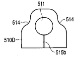
- FIGS. 19 and 20 are front views showing the bushes 510C and 510D used in the stabilizer bush 500 described above.
- the bushes 510C and 510D have a shape in which a recess 514 is provided.
- the split portions 515 a and 515 b for insertion into the torsion portion 21 are provided at positions avoiding the concave portion 514.
- FIG. 21 is an explanatory view showing a stabilizer bush 600 according to a sixth embodiment of the present invention.
- the stabilizer bushing 600 includes a bushing 610 attached to the outer periphery of the torsion part 21 via an adhesive, and a bracket 620 attached to the bushing 610 via an adhesive and attached to the vehicle body.
- the bush 610 is formed of a rubber material and includes a circular hole 611 having a shape along the outer peripheral surface of the attachment portion 21a.
- the bracket 620 is formed by bending a metal plate, and is formed at a bent portion 621 having an inner wall surface 621a formed along the outer wall surface 612 of the bush 610, and at both ends of the bent portion 621. And a joint portion 622 provided for joining with F.
- the bracket 620 is caulked and attached to the outer wall surface 612 of the bush 610.
- the adhesive is not scraped off when the bush 610 and the bracket 620 are fitted, and the adhesive can be saved.
- the amount of tightening when caulking takes into account the amount of springback of the bracket.
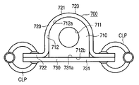
- FIG. 22 is a front view showing a stabilizer bush 700 according to the seventh embodiment of the present invention.
- the stabilizer bush 700 includes a bush 710 attached to the outer periphery of the torsion part 21 via an adhesive, a bracket 720 attached to the bush 710 via an adhesive, and attached to the vehicle body, and a fixing plate 730. It has.
- the bush 710 is formed of a rubber material and includes a circular hole 711 having a shape along the outer peripheral surface of the attachment portion 21a. Note that the outer wall surface 712 of the bush 710 includes a circular portion 712a located in the upper portion in FIG. 22 and a flat portion 712b located in the lower portion.
- the bracket 720 is formed by bending a metal plate, and is formed at a bent portion 721 having an inner wall surface 721a formed along a portion 712a of the bushing 710, and at both ends of the bent portion 721, and the frame portion F And a joint portion 722 that is used for joining. Note that a bolt hole 722 a is formed in the joint portion 722.
- the fixing plate 730 has a flat plate body 731, and the upper surface 731 a of the plate body 731 is bonded to the portion 712 b of the bush 710. Note that bolt holes 731b are formed on both ends of the plate body 731. Since there is a fastening allowance between the bush 710 and the bracket 720, it is necessary to bond the fixing plate 730 in the adhesive curing process. Specifically, a bolt BLT is inserted into the bolt hole 722a and the bolt hole 731b, and the bush 710, the bracket 720, and the fixing plate 730 are mechanically coupled together.
- the adhesion area can be increased along with the adhesion between the bush 710 and the fixing plate 730, and the adhesive force can be further strengthened by the integral connection.
- the bush 710, the bracket 720, and the fixing plate 730 may be mechanically coupled integrally using a clamp jig CLP using a spring material instead of the bolt BLT.
- the bonding between the bush 710 and the fixed plate 730 is not necessarily required.
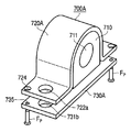
- FIG. 24 is a perspective view showing a stabilizer bush 700A according to a modification of the stabilizer bush 700 described above, and FIG. 25 is a side view showing the stabilizer bush 700A.
- 24 and 25 the same functional parts as those in FIG. 22 are denoted by the same reference numerals, and detailed description thereof is omitted.
- the stabilizer bush 700A uses a bracket 720A instead of the bracket 720 and a fixed plate 730A instead of the fixed plate 730.
- the bracket 720A and the fixing plate 730A are provided with positioning pin holes 724 and 735, respectively.
- the frame F is provided with pins Fp to be inserted into the pin holes 724 and 735.
- the same effect as that of the stabilizer bush 700 described above can be obtained, and the pin holes 724 and 735 are inserted into the pins Fp provided in the frame part F, whereby the frame part F can be aligned with the bracket 720A and the fixing plate 730A.
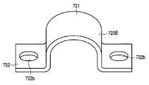
- FIG. 26 is a perspective view showing a bracket 720B according to a modification of the bracket 720 in the stabilizer bush 700 described above.
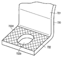
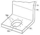
- the bracket 720B has a long hole-shaped bolt hole 722b instead of one bolt hole 722a of the pair of bolt holes 722a in the bracket 720. If comprised in this way, the assembly
- a countermeasure against loosening may be taken by increasing the friction of the fastening surface.
- a roughened surface 722c by shot blasting is formed around the bolt hole 722b.
- a knurled surface 722d may be formed as shown in FIG. Further, as shown in FIG. 30, a fine protrusion 722e may be formed.
Landscapes
- Engineering & Computer Science (AREA)
- General Engineering & Computer Science (AREA)
- Mechanical Engineering (AREA)
- Vehicle Body Suspensions (AREA)
- Springs (AREA)
- Vibration Prevention Devices (AREA)
Abstract
車両幅方向に延びるトーション部(21)と、このトーション部(21)の両端部から車両前後方向に延びるアーム部(23)とを有する車両用スタビライザ(10)に取り付けられるスタビライザ用ブシュ(100)において、トーション部(21)の外周部に接着剤を介して取り付けられたブシュ(110)と、ブシュ(110)に接着剤を介して固着され、フレーム部(F)に取り付けられるブラケット(120)とを備え、スタビライザバーとの位置ずれや泥水の浸入を防ぐことで、操縦安定性・乗り心地を改善するとともに、異音の発生を防止する。
Description
本発明は、車両スタビライザに用いられるスタビライザ用ブシュ及びこのスタビライザ用ブシュが組み込まれた車両スタビライザに関し、特に、車両の安定性・操縦性を向上させることができる技術に関する。
スタビライザ用ブシュが組み込まれた車両用スタビライザは、スタビライザバーを車両の懸架装置に連結し、スタビライザバーのねじり反力を利用して車両の姿勢を安定させる機能を有している。例えば車両用スタビライザは、U字状に形成されたスタビライザバーの両端を懸架装置の作動部分に連結させ、スタビライザバーのトーション部を車体フレームにスタビライザ用ブシュ(固定部材)で固定させ、ねじり反力を受けるように構成されている(例えば、特開2001-270315号公報参照)。
スタビライザ用ブシュは、トーション部の所定位置を把持する形状であり、車体フレーム側に固定されている。なお、スタビライザ用ブシュは一般的にすべりブシュであり、トーション部の軸方向に沿って相対的に動く構造となっていた。
上述したスタビライザ用ブシュをスタビライザバーに装着したものでは、次のような問題があった。すなわち、スタビライザ用ブシュがトーション部の軸方向に沿って相対的に動くことから、スタビライザ用ブシュがトーション部以外の部品に干渉し、異音が発生することがあった。また、スタビライザ用ブシュとトーション部との相対的な位置関係がずれることで、車両用スタビライザとしての性能が不安定であり、操縦安定性・乗り心地等に悪影響を与えていた。
また、トーション部とスタビライザ用ブシュとの隙間に泥水が浸入し、擦れによる異音が生じるという問題があった。
さらに、上記のような不具合の改善策として、トーション部に曲げ加工を施すことで、トーション部とスタビライザ用ブシュとの位置ずれ防止を図る方法があるが、製造コストが上昇するという問題があった。
そこで本発明は、スタビライザバーとの位置ずれや泥水の浸入を防ぐことで、操縦安定性・乗り心地を改善するとともに、異音の発生を防止することができるスタビライザ用ブシュ及び車両スタビライザを提供することを目的としている。
上記目的を満足するため本発明のスタビライザ用ブシュは、車両幅方向に延びるトーション部と、このトーション部の両端部から車両前後方向に延びるアーム部とを有する車両用スタビライザに取り付けられるスタビライザ用ブシュにおいて、上記トーション部の外周部に接着剤を介して取り付けられたブシュと、このブシュに接着剤を介して固着され、車両本体に取り付けられるブラケットとを備えている。
上記目的を満足するため本発明の車両スタビライザは、車両幅方向に延び、被係合部を有するトーション部と、このトーション部の両端部から車両前後方向に延びるアーム部と、係合部を有し、上記トーション部の被係合部に係合して取り付けられるスタビライザ用ブシュとを備え、上記被係合部は、ローレット加工あるいは2面幅加工され、上記スタビライザ用ブシュは、上記トーション部の外周部に接着剤を介して取り付けられたブシュと、このブシュに接着剤を介して固着され、車両本体に取り付けられるブラケットとを備えている。
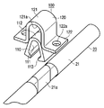
図1は本発明の第1の実施の形態に係る車両用スタビライザ10及び車両前輪の懸架装置Kを示す斜視図、図2は車両用スタビライザ10に組み込まれたスタビライザバー20のトーション部21へのスタビライザ用ブシュ(固定部材)30を示す斜視図である。
車両用スタビライザ10は、中空部材または中実部材から構成されたスタビライザバー20と、スタビライザバー20を車体のフレーム部Fに固定するスタビライザ用ブシュ100と、スタビライザバー20の先端23aを懸架装置Kの作動部分に連結させるスタビライザリンク30とを備えている。
スタビライザバー20は、車体の幅方向に渡されたトーション部21と、このトーション部21の両端に位置し、肩部22と、この肩部22からそれぞれ車両前後方向に延び、アーム部23とを備え、略U字状に形成されている。
スタビライザバー20は、懸架装置Kの作動部分が上下動すると、アーム部23がそれに追従して作動し、トーション部21にねじれが生じ、そのねじれ反力により懸架装置Kを安定に保持する機能を有している。トーション部21のスタビライザ用ブシュ100に対応する取付部位21aは、断面が長円状に圧延・切削等により変形加工されている(例えば、2面幅加工)。
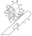
図2に示すように、スタビライザ用ブシュ100は、トーション部21の外周部に接着剤(エポキシ系接着剤または後加硫接着剤)を介して取り付けられたブシュ110と、このブシュ110に接着剤を介して固着され、車両本体に取り付けられるブラケット120とを備えている。
ブシュ110は、ゴム材で形成され、取付部位21aの外周面に沿った形状の内壁面111が設けられている。また、外壁面112は円弧部及び直線部から形成されている。さらに、図2中下部には開口部となるブシュ割り部113が形成されている。
ブラケット120は、金属板を折曲して形成され、ブシュ110の外壁面112に沿って形成された内壁面121aを有する曲成部121と、この曲成部121の両端に形成され、フレーム部Fとの接合に供される接合部122とを備えている。なお、接合部122にはボルト孔122aが形成されている。
懸架装置Kは、例えば、ダブルウィシュボーンタイプの懸架装置であり、左右に設けられた車軸部Kaに前輪等(不図示)が取り付けられる。
上述したスタビライザ用ブシュ100は次のような工程で製造される。すなわち、スタビライザバー20のトーション部21の取付部位21aにエポキシ系接着剤または後加硫接着剤を塗布した後に、ブシュ割り部113を広げて所定の位置に合わせて接着する。また、ブッシュ110の内壁面111にも接着剤を塗布する。この後、スタビライザバー20にエポキシ系粉体塗装を施行し、接着力をより強固にする。
接着力確保のため、ブラケット120の表面処理はカチオン塗装又は亜鉛メッキを使用するようにしてもよい。
次に、ブシュ110の内壁面111及び外壁面112に接着剤を塗布し、ブラケット120を重ね合わせる。
このように構成された車両用スタビライザ10は、次のように作動する。すなわち、例えば車両走行中に、片側の車輪が窪みに入り、懸架装置Kの一方が下がったとする。すると、左右のアーム部23に挟み角が生じ、あるいは挟み角が広がるので、トーション部21がねじられ、ねじれ反力が生じる。このねじれ反力によりトーション部21が元の状態に戻り、懸架装置Kを元の位置に戻す。
このとき、フレーム部Fとブラケット120はボルト止め、ブラケット120とブシュ110とは接着剤により堅固に固着されている。また、取付部位21aは2面幅加工により平坦面が形成されているため、より接着力が強固になる。したがって、フレーム部Fとトーション部21の取付部位21aとの相対的な位置ずれが発生しない。
一方、ブラケット120とブシュ110のずれ阻止力が入力荷重に勝る場合には、ブラケット120とブシュ110の接着面積を縮小するようにしてもよい。
このため、以下の効果が得られる。すなわち、ブシュ110やブラケット120が取付部位21aから動かないため、他部品との干渉が回避できる。また、ノミナル(正規)位置で安定することによりスタビライザバー20のたわみ特性が安定する。
また、旋回時等の逆相ストローク時においては、トレースの正確性が向上する。このため、タイヤのフローティング感が減り、官能評価が向上する。
一方、直進時等の同相ストローク時においては、断続的にスリップするスティックスリップが生じないためストロークがリニア特性を有し、不連続感が無く、乗り心地が向上する。
また、スタビライザ用ブシュ100やブラケット120との間に泥水が浸入することがないので、擦れによる異音が発生することを防止できる。
さらに、トーション部21に、スタビライザ用ブシュ100のずれ防止のための曲げ加工やずれ止め用としてブシュ側にアルミリングやゴムクランプを装着する必要がない。したがって、部品点数を削減できるとともに、設計自由度が向上する。
このように本実施の形態に係るスタビライザ用ブッシュ30では、スタビライザバー20との位置ずれや泥水の浸入を防ぐことで、操縦安定性・乗り心地を改善するとともに、異音の発生を防止することができる。
なお、ブシュ110の内壁面111及びスタビライザバー20の塗装表面のいずれか又は双方に梨地処理を施すことで、アンカー効果を加え、接着力をさらに向上させるようにしてもよい。
通常、スタビリンクの揺動角はスタビライザとブシュのずれ量も考慮され、設計されるが、接着によりずれ量がゼロになるため、スタビリンクの必要揺動角を減少させることができ、コストダウンやシール耐久性へのタフネス向上が期待できる。また、スタビライザとブシュにずれが生じた際、このずれが止まってからスタビライザが応答するが、ずれが無くなることによりスタビライザ応答性が向上する。
図3~図5は上述したスタビライザ用ブシュ100が取り付けられるトーション部21の取付部位21aの変形例を示す図である。すなわち、図3は、2面幅加工の構造が単純化されたものであり、同様の効果を得ることができるとともに、加工コストを抑えることができる。
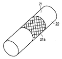
図4,5は、トーション部21の取付部位21aにローレット加工を施したものである。ローレット加工によりアンカー効果が生じ、接着力を強化することができる。また、前述した2面幅加工に比べて、加工コストを抑えることができる。
図6は、本発明の第2の実施の形態に係るスタビライザ用ブシュ200を示す側面図である。
スタビライザ用ブシュ200は、トーション部21の外周部に接着剤を介して取り付けられたブシュ210と、このブシュ210に接着剤を介して固着され、車両本体に取り付けられるブラケット220とを備えている。
ブシュ210は、ゴム材で形成され、取付部位21aの外周面に沿った形状の円形孔211を備えている。また、外壁面212には突起213が設けられている。
ブラケット220は、金属板を折曲して形成され、ブシュ210の外壁面212に沿って形成された内壁面221aを有する曲成部221と、この曲成部221の両端に形成され、フレーム部Fとの接合に供される接合部222とを備えている。なお、接合部222にはボルト孔222aが形成されている。
このように構成されたスタビライザ用ブシュ200では、ブシュ210とブラケット220との間の接着面積を増大させることができ、接着力を強化することができる。また、前述した2面幅加工に比べて、加工コストを抑えることができる。
図7は、上述したスタビライザ用ブシュ200の変形例に係るスタビライザ用ブシュ200Aを示す図である。図7において図6と同一機能部分には同一符号を付している。スタビライザ用ブシュ200Aは、外壁面212に設けられた突起213Aを備えている。突起213Aは突起213と同様に接着面積を増大させるとともに、物理的にずれにくい形状とすることで、接着力を強化している。
図8は、本発明の第3の実施の形態に係るスタビライザ用ブシュ300を一部切欠して示す斜視図である。
スタビライザ用ブシュ300は、トーション部21の外周部に接着剤を介して取り付けられたブシュ310と、このブシュ310に接着剤を介して固着され、車両本体に取り付けられるブラケット320とを備えている。
ブシュ310は、ゴム材で形成され、取付部位21aの外周面に沿った形状の円形孔311を備えている。また、外壁面312には溝313が設けられている。
ブラケット320は、金属板を折曲して形成され、ブシュ310の外壁面312に沿って形成された内壁面321aを有する曲成部321と、この曲成部321の両端に形成され、フレーム部Fとの接合に供される接合部322とを備えている。なお、接合部322にはボルト孔322aが形成されている。
なお、ブシュ310とブラケット320の接着に際して、溝313に接着剤を供給し、曲成部321を押し付けることで接着剤が溝313から溢れ、外壁面312に広がる。接着剤の量を調整することで、接着剤の過不足を制御することができる。
このように構成されたスタビライザ用ブシュ300では、ブシュ310とブラケット320との間の接着面積を増大させることができ、接着力を強化することができる。さらに、ブシュ310とブラケット320のトーション部21の軸方向における相対移動が溝313と曲成部321との係合により規制されるので、接着力を補強することが可能となる。
図9は、本発明の第4の実施の形態に係るスタビライザ用ブシュ400を示す斜視図である。
スタビライザ用ブシュ400は、トーション部21の外周部に接着剤を介して取り付けられたブシュ410と、このブシュ410に接着剤を介して固着され、車両本体に取り付けられるブラケット420とを備えている。
ブシュ410は、ゴム材で形成され、取付部位21aの外周面に沿った形状の円形孔411を備えている。また、トーション部21の軸方向両端部にはフランジ部412が設けられている。
ブラケット420は、金属板を折曲して形成され、ブシュ410の外壁面412に沿って形成された曲成部421と、この曲成部421の両端に形成され、フレーム部Fとの接合に供される接合部422とを備えている。なお、接合部422にはボルト孔422aが形成されている。
このように構成されたスタビライザ用ブシュ400では、ブシュ410とブラケット420のトーション部21の軸方向における相対移動がフランジ部412と曲成部421との係合により規制されるので、接着力を補強することが可能となる。
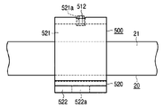
図10は、本発明の第5の実施の形態に係るスタビライザ用ブシュ500を示す斜視図、図11は同スタビライザ用ブシュ500を示す側面図である。
スタビライザ用ブシュ500は、トーション部21の外周部に接着剤を介して取り付けられたブシュ510と、このブシュ510に接着剤を介して固着され、車両本体に取り付けられるブラケット520とを備えている。
ブシュ510は、ゴム材で形成され、取付部位21aの外周面に沿った形状の円形孔511を備えている。また、トーション部21の軸方向中央部に突起512が設けられている。
ブラケット520は、金属板を折曲して形成され、ブシュ510の外壁面512に沿って形成された曲成部521と、この曲成部521の両端に形成され、フレーム部Fとの接合に供される接合部522とを備えている。なお、曲成部521には上述した突起512との係合に供される孔部521a、接合部522にはボルト孔522aが形成されている。
このように構成されたスタビライザ用ブシュ500では、ブシュ510とブラケット520のトーション部21の軸方向における突起512と孔部521aとの係合により規制されるので、接着力を補強することが可能となる。
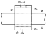
図12は、上述したスタビライザ用ブシュ500の変形例に係るスタビライザ用ブシュ500Aを示す斜視図、図13は同スタビライザ用ブシュ500Aを示す側面図である。なお、図12,13において、図10,11と同一機能部分には同一符号を付し、その詳細な説明は省略する。
スタビライザ用ブシュ500は、トーション部21の外周部に接着剤を介して取り付けられたブシュ510Aと、このブシュ510Aに接着剤を介して固着され、車両本体に取り付けられるブラケット520Aとを備えている。
ブシュ510Aでは、突起512の代わりに突起512Aが設けられている。また、曲成部521には上述した突起512Aとの係合に供される孔部521bが形成されている。なお、突起512Aは突起512に対し、軸方向に長く形成されている。
このように構成されたスタビライザ用ブシュ500Aでは、ブシュ510Aとブラケット520Aのトーション部21の軸方向における突起512Aと孔部521bとの係合により規制されるので、接着力を補強することが可能となる。
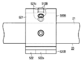
図14は、上述したスタビライザ用ブシュ500の変形例に係るスタビライザ用ブシュ500Bを示す斜視図、図15は同スタビライザ用ブシュ500Bを示す側面図である。なお、図14,15において、図10,11と同一機能部分には同一符号を付し、その詳細な説明は省略する。
スタビライザ用ブシュ500は、トーション部21の外周部に接着剤を介して取り付けられたブシュ510Bと、このブシュ510Bに接着剤を介して固着され、車両本体に取り付けられるブラケット520Bとを備えている。
ブシュ510Bでは、突起512の代わりに複数の突起512Bが設けられている。また、曲成部521には上述した突起512Bとの係合に供される複数の孔部521cが形成されている。
このように構成されたスタビライザ用ブシュ500Bでは、ブシュ510Bとブラケット520Bのトーション部21の軸方向における突起512Bと孔部521cとの係合により規制されるので、接着力を補強することが可能となる。
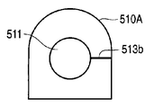
図16~図18は、上述したスタビライザ用ブシュ500に用いられるブシュ510を示す正面図である。ブシュ510には、トーション部21に挿入するための割り部513a~513cが設けられている。
図16に示すブシュ510の割り部513aは一般的なものであり、トーション部21への挿入作業が最も容易に行えるとともに、ブシュ510を広げた際にブシュ510への負担が最も小さい部位(ゴム厚最薄部の対向部)に位置に設けられている。図17に示すブシュ510Aでは、割り部513bは側方に設けられているものであり、トーション部21からの荷重が低くなる位置に設けられている。図18に示すブシュ510Bは、円形孔511Aの位置が偏心している。この場合、割り部513cは厚みが大きい部位に設けられている。
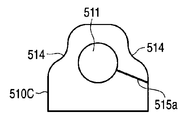
図19,図20は、上述したスタビライザ用ブシュ500に用いられるブシュ510C,510Dを示す正面図である。ブシュ510C,510Dは、凹部514が設けられている形状となっている。図19及び図20に示すように、トーション部21に挿入するための割り部515a,515bは凹部514を避けた位置に設けられている。
図21は、本発明の第6の実施の形態に係るスタビライザ用ブシュ600を示す説明図である。
スタビライザ用ブシュ600は、トーション部21の外周部に接着剤を介して取り付けられたブシュ610と、このブシュ610に接着剤を介して固着され、車両本体に取り付けられるブラケット620とを備えている。
ブシュ610は、ゴム材で形成され、取付部位21aの外周面に沿った形状の円形孔611を備えている。
ブラケット620は、金属板を折曲して形成され、ブシュ610の外壁面612に沿って形成された内壁面621aを有する曲成部621と、この曲成部621の両端に形成され、フレーム部Fとの接合に供される接合部622とを備えている。
なお、ブシュ610とブラケット620の接着に際して、ブラケット620をカシメてブシュ610の外壁面612に取り付ける。
このように構成されたスタビライザ用ブシュ600では、ブシュ610とブラケット620との嵌め合い時に接着剤がそぎ落とされず、接着剤を節約することができる。なお、カシメる際の締め量は、ブラケットのスプリングバック量を考慮したものとする。
図22は、本発明の第7の実施の形態に係るスタビライザ用ブシュ700を示す正面図である。
スタビライザ用ブシュ700は、トーション部21の外周部に接着剤を介して取り付けられたブシュ710と、このブシュ710に接着剤を介して固着され、車両本体に取り付けられるブラケット720と、固定プレート730とを備えている。
ブシュ710は、ゴム材で形成され、取付部位21aの外周面に沿った形状の円形孔711を備えている。なお、ブシュ710の外壁面712は、図22中上部に位置する円形状の部位712aと、下部に位置する平坦状の部位712bとを備えている。
ブラケット720は、金属板を折曲して形成され、ブシュ710の部位712aに沿って形成された内壁面721aを有する曲成部721と、この曲成部721の両端に形成され、フレーム部Fとの接合に供される接合部722とを備えている。なお、接合部722にはボルト孔722aが形成されている。
固定プレート730は、平板状の板体731を有し、この板体731の上面731aがブシュ710の部位712bに接着されている。なお、板体731の両端側には、ボルト孔731bが形成されている。なお、ブシュ710とブラケット720間には締め代があるため、接着剤キュア工程において固定プレート730を結合する必要がある。具体的には、ボルト孔722aとボルト孔731bにはボルトBLTが挿入されており、ブシュ710、ブラケット720、固定プレート730が機械的に一体に結合されている。
このように構成されたスタビライザ用ブシュ700では、ブシュ710と固定プレート730との接着に伴って、接着面積を増大させることができるとともに、一体結合により、接着力をより強化することができる。
なお、図23に示すようにボルトBLTの代わりに、バネ材を用いたクランプ治具CLPを用いて、ブシュ710、ブラケット720、固定プレート730を機械的に一体に結合するようにしてもよい。なお、入力荷重が低い場合には、ブシュ710と固定プレート730との接着は必ずしも必要ではない。
図24は、上述したスタビライザ用ブシュ700の変形例に係るスタビライザ用ブシュ700Aを示す斜視図、図25は同スタビライザ用ブシュ700Aを示す側面図である。なお、図24,25において、図22と同一機能部分には同一符号を付し、その詳細な説明は省略する。
スタビライザ用ブシュ700Aは、ブラケット720の代わりにブラケット720A、固定プレート730の代わりに固定プレート730Aを用いている。
ブラケット720A及び固定プレート730Aには、それぞれ位置決め用のピン孔724、735が設けられている。一方、フレーム部Fにはピン孔724、735に挿入されるピンFpが設けられている。
このように構成されたスタビライザ用ブシュ700Aでは、上述したスタビライザ用ブシュ700と同様の効果が得られるとともに、フレーム部Fに設けられたピンFpにピン孔724、735を挿入することで、フレーム部Fとブラケット720A及び固定プレート730Aとの位置合わせを行うことができる。
図26は、上述したスタビライザ用ブシュ700におけるブラケット720の変形例に係るブラケット720Bを示す斜視図である。ブラケット720Bは、ブラケット720における一対のボルト孔722aのうち、一方のボルト孔722aの代わりに、長孔状のボルト孔722bが形成されている。このように構成されていると、フレーム部Fへの組付け性が向上する。なお、図27に示すように、ボルト孔722bを両側に設けても良い。
なお、長孔状のボルト孔722bでは、締結面積が減少するため、締結面のフリクションを増大させることで緩み対策を施してもよい。例えば、図28は、ボルト孔722bの周囲には、ショットブラストによる粗加工面722cが形成されている。
また、図29に示すようにローレット加工面722dを形成してもよい。さらに、図30に示すように、微細な突起部722eを形成してもよい。
なお、本発明は前記実施の形態に限定されるものではない。この他、本発明の要旨を逸脱しない範囲で種々変形実施可能であるのは勿論である。
スタビライザバーとの位置ずれや泥水の浸入を防ぐことで、操縦安定性・乗り心地を改善するとともに、異音の発生を防止することが可能となるスタビライザ用ブシュ及び車両スタビライザを提供できる。
Claims (7)
- 車両幅方向に延びるトーション部と、このトーション部の両端部から車両前後方向に延びるアーム部とを有する車両用スタビライザに取り付けられるスタビライザ用ブシュにおいて、
上記トーション部の外周部に接着剤を介して取り付けられたブシュと、
このブシュに接着剤を介して固着され、車両本体に取り付けられるブラケットとを備えていることを特徴とするスタビライザ用ブシュ。 - 上記ブラケットと上記ブシュの接着面には、上記トーション部の軸方向への移動を規制する係合部が設けられていることを特徴とする請求項1に記載のスタビライザ用ブシュ。
- 上記ブラケットと上記ブシュの接着面には、上記トーション部の軸方向への移動を規制する粗面加工が施されていることを特徴とする請求項1に記載のスタビライザ用ブシュ。
- 上記ブラケットは、上記ブシュの上面側に位置する上面材と、上記ブシュの下面側に位置するベース材とを備えていることを特徴とする請求項1に記載のスタビライザ用ブシュ。
- 上記上面材と上記ベース材は機械的に接合されていることを特徴とする請求項4に記載のスタビライザ用ブシュ。
- 上記ブラケットには、長孔状のボルト孔が形成され、このボルト孔周囲にはボルトとの滑り止め加工が施されていることを特徴とする請求項1に記載のスタビライザ用ブシュ。
- 車両幅方向に延び、被係合部を有するトーション部と、
このトーション部の両端部から車両前後方向に延びるアーム部と、
係合部を有し、上記トーション部の被係合部に係合して取り付けられるスタビライザ用ブシュとを備え、
上記被係合部は、ローレット加工、あるいは2面幅加工、あるいは粗面加工され、
上記スタビライザ用ブシュは、上記トーション部の外周部に接着剤を介して取り付けられたブシュと、
このブシュに接着剤を介して固着され、車両本体に取り付けられるブラケットとを備えていることを特徴とする車両スタビライザ。
Applications Claiming Priority (2)
| Application Number | Priority Date | Filing Date | Title |
|---|---|---|---|
| JP2010-031744 | 2010-02-16 | ||
| JP2010031744A JP2011168102A (ja) | 2010-02-16 | 2010-02-16 | スタビライザ用ブシュ及び車両スタビライザ |
Publications (1)
| Publication Number | Publication Date |
|---|---|
| WO2011102373A1 true WO2011102373A1 (ja) | 2011-08-25 |
Family
ID=44482958
Family Applications (1)
| Application Number | Title | Priority Date | Filing Date |
|---|---|---|---|
| PCT/JP2011/053256 Ceased WO2011102373A1 (ja) | 2010-02-16 | 2011-02-16 | スタビライザ用ブシュ及び車両スタビライザ |
Country Status (2)
| Country | Link |
|---|---|
| JP (1) | JP2011168102A (ja) |
| WO (1) | WO2011102373A1 (ja) |
Cited By (7)
| Publication number | Priority date | Publication date | Assignee | Title |
|---|---|---|---|---|
| CN105270131A (zh) * | 2014-07-02 | 2016-01-27 | 丰田自动车株式会社 | 稳定杆支承装置 |
| JP2016203966A (ja) * | 2015-04-16 | 2016-12-08 | トヨタ自動車株式会社 | スタビライザブッシュ、スタビライザバー取付装置 |
| US9931902B2 (en) | 2015-04-16 | 2018-04-03 | Toyota Jidosha Kabushiki Kaisha | Stabilizer bushing and stabilizer-bar mounting device |
| US10052929B2 (en) | 2012-10-26 | 2018-08-21 | Nhk Spring Co., Ltd. | Bush for stabilizer, fastening tool, and fastening method |
| US20190135069A1 (en) * | 2017-11-06 | 2019-05-09 | Toyota Jidosha Kabushiki Kaisha | Stabilizer bushing |
| DE102019003884A1 (de) * | 2019-06-03 | 2020-12-03 | Sumitomo Riko Company Limited | Halterung für einen Fahrzeugstabilisator, Fahrzeugstabilisator und Verfahren |
| DE102013205852B4 (de) | 2012-04-09 | 2021-08-26 | GM Global Technology Operations LLC (n. d. Gesetzen des Staates Delaware) | Buchsen-befestigungsanordnung für ein fahrzeug mit querstabilisator sowie damit ausgerüstetes fahrzeug |
Families Citing this family (4)
| Publication number | Priority date | Publication date | Assignee | Title |
|---|---|---|---|---|
| JP6075167B2 (ja) * | 2012-04-18 | 2017-02-08 | Jfeスチール株式会社 | 自動車の足回り部材の溶接部塗装後耐食性改善方法および自動車の足回り部材ならびに自動車の足回り部材の製造方法 |
| JP6339544B2 (ja) | 2015-09-17 | 2018-06-06 | 住友理工株式会社 | ブッシュ付スタビライザバー |
| JP6731318B2 (ja) * | 2016-08-31 | 2020-07-29 | 住友理工株式会社 | スタビライザブッシュ付きスタビライザバーの製造方法とスタビライザブッシュの接着用治具、スタビライザバーのスタビライザブッシュ接着品 |
| JP7265142B2 (ja) * | 2019-05-27 | 2023-04-26 | 日本製鉄株式会社 | 溶融亜鉛めっき鋼板 |
Citations (7)
| Publication number | Priority date | Publication date | Assignee | Title |
|---|---|---|---|---|
| JP3027743U (ja) * | 1996-02-08 | 1996-08-13 | シントク工業株式会社 | 連結プレート |
| JPH11303917A (ja) * | 1998-04-21 | 1999-11-02 | Kinugawa Rubber Ind Co Ltd | 車両用スタビライザブッシュ及びそれを用いるスタビライザバーの支持部構造 |
| JP2001182767A (ja) * | 1999-12-24 | 2001-07-06 | Kinugawa Rubber Ind Co Ltd | 車両用スタビライザブッシュの取付構造 |
| US20040070161A1 (en) * | 2002-10-15 | 2004-04-15 | Fader Joseph A. | Stabilizer bar with bushings that remain fixed to the bar |
| JP2006170293A (ja) * | 2004-12-14 | 2006-06-29 | Toyo Tire & Rubber Co Ltd | 防振装置及びその取付方法 |
| JP2007127239A (ja) * | 2005-11-07 | 2007-05-24 | Toyo Tire & Rubber Co Ltd | ゴムブッシュ付きバー |
| JP2010030421A (ja) * | 2008-07-29 | 2010-02-12 | Nhk Spring Co Ltd | スタビライザ装置およびその製造方法 |
-
2010
- 2010-02-16 JP JP2010031744A patent/JP2011168102A/ja active Pending
-
2011
- 2011-02-16 WO PCT/JP2011/053256 patent/WO2011102373A1/ja not_active Ceased
Patent Citations (7)
| Publication number | Priority date | Publication date | Assignee | Title |
|---|---|---|---|---|
| JP3027743U (ja) * | 1996-02-08 | 1996-08-13 | シントク工業株式会社 | 連結プレート |
| JPH11303917A (ja) * | 1998-04-21 | 1999-11-02 | Kinugawa Rubber Ind Co Ltd | 車両用スタビライザブッシュ及びそれを用いるスタビライザバーの支持部構造 |
| JP2001182767A (ja) * | 1999-12-24 | 2001-07-06 | Kinugawa Rubber Ind Co Ltd | 車両用スタビライザブッシュの取付構造 |
| US20040070161A1 (en) * | 2002-10-15 | 2004-04-15 | Fader Joseph A. | Stabilizer bar with bushings that remain fixed to the bar |
| JP2006170293A (ja) * | 2004-12-14 | 2006-06-29 | Toyo Tire & Rubber Co Ltd | 防振装置及びその取付方法 |
| JP2007127239A (ja) * | 2005-11-07 | 2007-05-24 | Toyo Tire & Rubber Co Ltd | ゴムブッシュ付きバー |
| JP2010030421A (ja) * | 2008-07-29 | 2010-02-12 | Nhk Spring Co Ltd | スタビライザ装置およびその製造方法 |
Cited By (10)
| Publication number | Priority date | Publication date | Assignee | Title |
|---|---|---|---|---|
| DE102013205852B4 (de) | 2012-04-09 | 2021-08-26 | GM Global Technology Operations LLC (n. d. Gesetzen des Staates Delaware) | Buchsen-befestigungsanordnung für ein fahrzeug mit querstabilisator sowie damit ausgerüstetes fahrzeug |
| US10052929B2 (en) | 2012-10-26 | 2018-08-21 | Nhk Spring Co., Ltd. | Bush for stabilizer, fastening tool, and fastening method |
| CN105270131A (zh) * | 2014-07-02 | 2016-01-27 | 丰田自动车株式会社 | 稳定杆支承装置 |
| CN105270131B (zh) * | 2014-07-02 | 2017-09-26 | 丰田自动车株式会社 | 稳定杆支承装置 |
| JP2016203966A (ja) * | 2015-04-16 | 2016-12-08 | トヨタ自動車株式会社 | スタビライザブッシュ、スタビライザバー取付装置 |
| US9931902B2 (en) | 2015-04-16 | 2018-04-03 | Toyota Jidosha Kabushiki Kaisha | Stabilizer bushing and stabilizer-bar mounting device |
| US20190135069A1 (en) * | 2017-11-06 | 2019-05-09 | Toyota Jidosha Kabushiki Kaisha | Stabilizer bushing |
| US10857850B2 (en) * | 2017-11-06 | 2020-12-08 | Toyota Jidosha Kabushiki Kaisha | Stabilizer bushing |
| DE102019003884A1 (de) * | 2019-06-03 | 2020-12-03 | Sumitomo Riko Company Limited | Halterung für einen Fahrzeugstabilisator, Fahrzeugstabilisator und Verfahren |
| US11331974B2 (en) | 2019-06-03 | 2022-05-17 | Sumitomo Riko Company Limited | Bracket for vehicle stabilizer, vehicle stabilizer and method for manufacturing vehicle stabilizer |
Also Published As
| Publication number | Publication date |
|---|---|
| JP2011168102A (ja) | 2011-09-01 |
Similar Documents
| Publication | Publication Date | Title |
|---|---|---|
| WO2011102373A1 (ja) | スタビライザ用ブシュ及び車両スタビライザ | |
| CN104755287B (zh) | 稳定器用衬套、粘接用工具及粘接方法 | |
| US9546705B2 (en) | Bush | |
| JP2013060196A (ja) | 車両スタビライザ | |
| CA2248823A1 (en) | Rubber/metal bearing for coupling a stabilizer bar to an automotive body | |
| US20180245654A1 (en) | Stabilizer bush | |
| CN110561998B (zh) | 纵臂总成 | |
| CN106183676A (zh) | 悬架臂 | |
| CN210082868U (zh) | 稳定杆固定装置、稳定杆总成以及车辆 | |
| JP4759428B2 (ja) | スタビライザブッシュ | |
| JP3963593B2 (ja) | 棒材のずれ防止構造 | |
| EP1953014A1 (en) | Structure for supporting stabilizer | |
| US7188851B2 (en) | Stabilizer for vehicle and method for mounting the same | |
| US20180154732A1 (en) | Stabilizer for a vehicle suspension | |
| KR200487124Y1 (ko) | 차량용 스테빌라이저 | |
| KR102070272B1 (ko) | 스태빌라이저용 부시 | |
| JPH11210713A (ja) | ずれ防止固定リング | |
| JP2001182767A (ja) | 車両用スタビライザブッシュの取付構造 | |
| KR20210062133A (ko) | 차량용 스테빌라이저바의 부시 장치 | |
| EP3632717A1 (en) | Joint structure of stabilizer link | |
| CN210211937U (zh) | 控制臂总成 | |
| US20070194549A1 (en) | Bearing element for a motor vehicle stabilizer | |
| JP2013224119A (ja) | ショックアブソーバの組付治具 | |
| KR20060070011A (ko) | 자동차용 로어암 어셈블리와 볼 조인트 어셈블리의 결합구조 | |
| KR100880167B1 (ko) | 너클 브라켓 |
Legal Events
| Date | Code | Title | Description |
|---|---|---|---|
| 121 | Ep: the epo has been informed by wipo that ep was designated in this application |
Ref document number: 11744659 Country of ref document: EP Kind code of ref document: A1 |
|
| NENP | Non-entry into the national phase |
Ref country code: DE |
|
| 122 | Ep: pct application non-entry in european phase |
Ref document number: 11744659 Country of ref document: EP Kind code of ref document: A1 |