WO2011102261A1 - 料金収受システム - Google Patents
料金収受システム Download PDFInfo
- Publication number
- WO2011102261A1 WO2011102261A1 PCT/JP2011/052590 JP2011052590W WO2011102261A1 WO 2011102261 A1 WO2011102261 A1 WO 2011102261A1 JP 2011052590 W JP2011052590 W JP 2011052590W WO 2011102261 A1 WO2011102261 A1 WO 2011102261A1
- Authority
- WO
- WIPO (PCT)
- Prior art keywords
- vehicle
- information
- billing
- area
- extended
- Prior art date
- Legal status (The legal status is an assumption and is not a legal conclusion. Google has not performed a legal analysis and makes no representation as to the accuracy of the status listed.)
- Ceased
Links
Images







Classifications
-
- G—PHYSICS
- G08—SIGNALLING
- G08G—TRAFFIC CONTROL SYSTEMS
- G08G1/00—Traffic control systems for road vehicles
- G08G1/09—Arrangements for giving variable traffic instructions
-
- G—PHYSICS
- G08—SIGNALLING
- G08G—TRAFFIC CONTROL SYSTEMS
- G08G1/00—Traffic control systems for road vehicles
- G08G1/01—Detecting movement of traffic to be counted or controlled
- G08G1/017—Detecting movement of traffic to be counted or controlled identifying vehicles
-
- G—PHYSICS
- G07—CHECKING-DEVICES
- G07B—TICKET-ISSUING APPARATUS; FARE-REGISTERING APPARATUS; FRANKING APPARATUS
- G07B15/00—Arrangements or apparatus for collecting fares, tolls or entrance fees at one or more control points
- G07B15/06—Arrangements for road pricing or congestion charging of vehicles or vehicle users, e.g. automatic toll systems
-
- G—PHYSICS
- G07—CHECKING-DEVICES
- G07B—TICKET-ISSUING APPARATUS; FARE-REGISTERING APPARATUS; FRANKING APPARATUS
- G07B15/00—Arrangements or apparatus for collecting fares, tolls or entrance fees at one or more control points
- G07B15/06—Arrangements for road pricing or congestion charging of vehicles or vehicle users, e.g. automatic toll systems
- G07B15/063—Arrangements for road pricing or congestion charging of vehicles or vehicle users, e.g. automatic toll systems using wireless information transmission between the vehicle and a fixed station
Definitions
- the present invention relates to a toll collection system, and more particularly to a toll collection system that collects a predetermined fee from the owner of a vehicle that has entered a toll road or a billing target area.
- road pricing for example, a gantry in which a wireless communication device for charging is installed is provided at each entrance / exit of a charging target area, and charging processing is performed when a vehicle passes through the gantry.
- a charging method for example, a method of subtracting a certain amount of charge from the balance of the prepaid card inserted in the vehicle-mounted device, and updating and recording the remaining amount as a balance on the prepaid card, or from a bank account of a user registered in advance. A method that automatically deducts a certain fee is used.
- An ETC (Electronic Toll Collection) system is known as a system that automatically collects road usage fees.
- This ETC system can automatically collect a fee by performing wireless communication between a roadside wireless device installed at a toll booth and an onboard device mounted on a vehicle.
- a method of collecting a fee when an existing chargeable area is expanded is being studied. For example, in Patent Document 1, when the vehicle-mounted device detects whether or not it has entered the extended charging target area based on the position information acquired by the GPS receiver, and enters this existing detection target area
- a technique for collecting a road usage fee in an extended billing target area from the fee collecting device by notifying a fee collecting device installed in the billing target area is disclosed.
- the present invention has been made in view of such circumstances, and an object of the present invention is to provide a fee collection system capable of extending a chargeable area without changing an existing fee collection device.
- a center machine that is a host device of a toll collection device installed at a toll booth in a chargeable area, and an in-vehicle device that is provided in a vehicle and exchanges information with the center machine.
- the vehicle-mounted device includes a storage unit that stores map information of an extended charging target area newly set outside the charging target area, and a position information acquisition unit that acquires positional information of the vehicle.
- a controller that detects entry / exit information, which is information about the exit / exit of the vehicle, and outputs the entry / exit information to the center machine, wherein the center machine acquires the entry / exit information.
- the extended billing target area newly set outside the billing target area
- entry / exit information that is information on entry into and / or out of the billing area from the billing area is detected, Output to the center machine.
- the charge amount is calculated based on the acquired entry / exit information.
- the billing amount is calculated at the center machine based on the map information, the location information, and the entry / exit information between the extended billing area and the billing area. It is not necessary to set a flag or the like for determining whether or not the fee collection device side determines whether or not. For these reasons, it is not necessary to make any changes to the toll collection device, such as enabling flag determination and identifying entry / exit information, and the billing area can be expanded while using the existing toll collection device as it is. be able to.
- Information is exchanged between the in-vehicle device and the center device when the entry / exit information detected by the in-vehicle device is output to the center device, or when the charge amount information calculated by the center device is output to the in-vehicle device. It may be via a collection device, or may be via a device (for example, a wide-area communication device) that directly exchanges information between the vehicle-mounted device and the center device, and there is no limitation on the route of information exchange between the vehicle-mounted device and the center device. .
- a center machine that is a host device of a toll collection device installed at a toll booth in a chargeable area, and an in-vehicle device that is provided in a vehicle and exchanges information with the center machine.
- the vehicle-mounted device includes a storage unit that stores map information of an extended charging target area newly set outside the charging target area, and a position information acquisition unit that acquires positional information of the vehicle. Based on the map information and the location information, the entry of the vehicle that has entered the chargeable area from the extended chargeable area and / or the vehicle that has exited from the chargeable area to the extended chargeable area.
- a fee collection system including a calculation unit that calculates a charge amount based on a detection result when entry / exit information, which is exit information, is detected.
- the extended billing target area newly set outside the billing target area Based on this map information and the acquired location information, it is detected that the extended charging target area has entered the charging target area, and the charging amount is calculated based on the detection result.
- the charge amount is calculated in the vehicle-mounted device based on the map information, the position information, and the entry / exit information between the extended chargeable area and the chargeable area. It is not necessary to set a flag for making a determination on the receiving device side.
- the charge amount is calculated in the vehicle-mounted device in this way, it is not necessary to make a change operation such as enabling the flag collection device to determine the flag or identifying entry / exit information, and the existing fee collection device is used as it is.
- the billing area can be expanded.
- the billing amount calculated by the vehicle-mounted device when it is output to the center machine, it may be output to the center machine via a toll collection device, or a device that directly exchanges information with the center machine (for example, wide area communication) May be output to the center machine via the machine), and the route for sending and receiving collected amount (billing amount) information between the vehicle-mounted device and the center machine does not matter.
- the on-vehicle device of the fee collection system may further include a billing unit that charges the user for a billing amount corresponding to the billing amount information when the billing amount information is acquired. Since the charge amount is charged to the user from the vehicle-mounted device side, for example, the settlement process can be performed from an electromagnetic medium such as an IC card mounted on the vehicle-mounted device.
- the center device of the fee collection system may further include a billing unit that charges the user for a billing amount corresponding to the billing amount information when the billing amount information is acquired. Since the billing amount is charged to the user from the center machine, the settlement process can be performed by a process such as debiting from the bank account of the user via the center machine.
- the on-vehicle device of the toll collection system includes a first wide area communication device that exchanges the entry / exit information with the center device, and the center device exchanges the entry / exit information with the on-vehicle device.
- the center machine includes the entry / exit information of the on-board device charging area acquired from the on-board device via the toll collection device, the first wide area communication device, and the second wide area communication device.
- a fraud determination unit that compares the entry / exit information acquired from the vehicle-mounted device via the device and determines that the entry / exit information includes fraud if the comparison does not match. Good.
- the entry / exit information of the charging area acquired from the toll collection device side is compared with the entry / exit information of the charging area acquired from the wide area communication device side, for example, when the entry / exit information is falsified Can easily detect fraud such as tampering.
- the calculation unit of the fee collection system includes a storage device that stores first charging information related to an extended charging target area newly set outside the charging target area and second charging information related to the charging target area; An amount determining unit that determines the amount to be charged based on the entry / exit information, the first billing information, and the second billing information may be provided.
- the billing amount in the extended billing area and the billing amount in the billing area are collected together.
- the first billing information of the fee collection system includes a billing table using a stay time in the extended billing area as a parameter, and the amount determination unit receives the stay time in the extended billing area from the in-vehicle device.
- the billing amount in the extended billing target area may be determined using the stay time and the billing table. Since the staying time in the extended billing target area is taken into account in the billing amount calculation process, the billing amount can more accurately reflect the usage status of the road.
- the first billing information of the fee collection system includes a billing table using a travel distance in the extended billing area as a parameter, and the amount determination unit receives the travel distance in the extended billing area from the in-vehicle device.
- the billing amount in the extended billing target area may be determined using the travel distance and the billing table.
- the mileage in the extended charging target area is taken into consideration, so that the charging amount can more accurately reflect the road usage situation.
- the first billing information is provided for each of the extended billing target areas, and the entry / exit information includes the extended billing information.
- the extended charge target that is associated with the identification information of the target area, and the amount determination unit has entered the vehicle determined based on the entry / exit information associated with the identification information of the extended charge target area
- the charge amount may be determined using the first charge information of the area.
- the first billing information is registered corresponding to each extended billing target area, so that detailed charge setting can be performed for each extended billing target area. Further, even when the vehicle has entered a plurality of extended billing target areas, it is possible to collect charges in a lump.
- a return point table with the stay time in the chargeable area as a parameter is provided.
- the amount determination unit determines a return point using the stay time and the return point table when the stay time in the chargeable area is received from the onboard device, and the return point is owned by the vehicle. It may be given to a person.
- the chargeable area is an area where a certain amount of charge is collected at the time of entry, such as road pricing
- the point according to the stay time in the chargeable area is owned by the vehicle
- the user who has entered the billing area by mistake can be saved in financial terms.
- the present invention has an effect that the chargeable area can be expanded without changing the existing fee collection device.
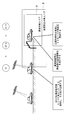
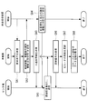
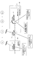
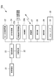
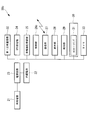
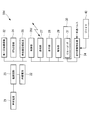
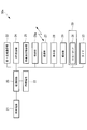
- FIG. 4 It is a figure showing the whole charge collection system composition concerning a 1st embodiment of the present invention. It is a block diagram which shows schematic structure of the fee collection apparatus which concerns on the 1st Embodiment of this invention. It is a figure when the approach lane of a charge object area is seen from the shoulder side. It is the figure which showed an example of the marking laid under the vehicle detector shown in FIG. It is the figure which showed the mode of the marking shown in FIG. 4 when a vehicle passed. It is a block diagram which shows schematic structure of the onboard equipment which concerns on the 1st Embodiment of this invention. It is a block diagram which shows schematic structure of the center machine which concerns on the 1st Embodiment of this invention.
- FIG. 1 is an overall configuration diagram of a fee collection system according to the present embodiment.
- the toll collection system 1 is configured such that the vehicle 3 enters the billing target area A and / or the billing target on all roads that pass through the boundary of the billing target area A that is the target area for road pricing.
- a toll collection device (not shown) for detecting exit from the area A is provided.
- the toll collection device is provided corresponding to an approach lane where the vehicle 3 enters the chargeable area A and an exit lane where the vehicle 3 exits from the chargeable area A, and the corresponding approach lane and exit lane
- the information on the vehicle-mounted device is exchanged with the vehicle-mounted device mounted on the vehicle 3 passing through the vehicle.
- FIG. 2 is a block diagram showing a schematic configuration of the fee collection system.
- the toll collection device 2 includes a first antenna 5, a camera 6, a vehicle detector 7, and a second antenna 8. Furthermore, the toll collection device 2 includes a first antenna controller 9 connected to the first antenna 5, a camera controller 10 connected to the camera 6, a vehicle detection controller 11 connected to the vehicle detector 7, and a second A second antenna controller 12 connected to the antenna 8 is provided.
- the toll collection device 2 further includes an overall controller 13, an environment controller 14 connected to the overall controller 13, and a communication controller 15 connected to the overall controller 13.
- the first antenna controller 9, camera controller 10, vehicle detection controller 11, second antenna controller 12, and general controller 13 are connected to each other via a bus 16 and can exchange information. It is said that.
- the communication controller 15 is communicably connected to a center device 17 that is a host device.
- the first antenna 5, the camera 6, the vehicle detector 7, and the second antenna 8 are gate-shaped support pillars arranged across the traveling road at the boundary of the chargeable area A. Is attached.
- FIG. 3 is a side view of the traveling lane.
- the 1st antenna 5 and the 2nd antenna 8 are installed so that it may be easy to receive the signal from onboard equipment of vehicles 3 which run the corresponding run lane.
- the first antenna 5 and the second antenna 8 are installed so that the antenna beam is directed to the corresponding travel lane.
- the first antenna 5 and the second antenna 8 acquire information on the vehicle-mounted device when the vehicle-mounted device passes near the area boundary of the chargeable area A.
- the first antenna 5 and the second antenna 8 are provided when the vehicle enters the charging target area A from the extended charging target area B (details will be described later) and / or the vehicle extends from the charging target area A.
- a request signal is output to the vehicle-mounted device, and the identification information of the vehicle-mounted device is acquired from the vehicle-mounted device.
- On-board device identification information includes the time of entry / exit (for example, year / month / day), the on-board device number assigned in advance to the on-board device, the IC card number inserted in the IC card interface of the on-vehicle device, etc. is there.
- the first antenna 5 and the second antenna 8 are installed with a distance of about 10 m to 15 m. This ensures the processing time until the vehicle-mounted device outputs a response signal to the second antenna 8 in accordance with a signal received by the vehicle-mounted device from the first antenna 5 (for example, a request signal for identification information of the vehicle-mounted device). It is for the purpose.
- the camera 6 is for photographing a license plate of an unauthorized vehicle when the unauthorized vehicle is detected.
- a vehicle without an on-board device a vehicle without an on-board device corresponding to the vehicle type, a vehicle with no IC card inserted into the on-vehicle device, or an IC card recorded more than the amount to be collected
- a vehicle having a small balance and being unable to charge normally a vehicle mounted with a counterfeited vehicle-mounted device or a counterfeit IC card, and the like.
- the determination as to whether the vehicle is an unauthorized vehicle is performed based on the identification information of the vehicle-mounted device acquired from the vehicle-mounted device by the first antenna 5 and the second antenna 8, and details of the method for determining an unauthorized vehicle will be described later.
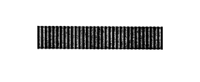
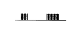
- the vehicle detector 7 detects that the vehicle 3 has passed. For example, the road below the vehicle detector 7 is marked with a striped pattern as shown in FIG.
- the vehicle detector 7 monitors the stripe pattern from above, and detects the passage of the vehicle 3 when the stripe pattern cannot be normally detected as shown in FIG.
- a newly set extended billing area B is set outside the billing area A.
- the extended billing area B is an area that is set afterwards when there is a request to expand the billing area A that originally existed.
- the extended charging target area B may be provided so as to surround the charging target area A, or a part thereof may be provided in contact with the charging target area A, or the charging target area A It may be an area that is provided separately without touching.
- no toll collection device is installed in the approach lane and the exit lane at the area boundary. Instead, the entry / exit is detected by the vehicle-mounted device mounted on the vehicle 3.
- FIG. 6 is a block diagram showing a schematic configuration of the vehicle-mounted device according to the present embodiment.
- the vehicle-mounted device 50 acquires information on position information from the power supply circuit 23 connected to the vehicle power supply 21 and the built-in battery 22, the first wide area communication device 32, and GPS satellites, and detects the current position. It communicates with the GPS receiver (position information acquisition unit) 24, the vehicle-mounted device storage device (storage unit) 25 that stores various information, the control unit 26, the first antenna 5, the second antenna 8, etc. of the toll collection device 2.
- the GPS receiver position information acquisition unit
- the vehicle-mounted device storage device storage unit 25 that stores various information
- the control unit 26 the first antenna 5, the second antenna 8, etc. of the toll collection device 2.
- a communication unit 27, a display unit 28, a buzzer, an LED notification unit 29, an IC card insertion unit (billing unit) 30 into which an IC card is inserted, and an IC card interface 31 provided in the IC card insertion unit 30 are provided. .
- various components such as the GPS receiver 24 may not necessarily be built in the vehicle-mounted device 50.
- each component may be configured in a state where information can be exchanged.
- the first wide area communication device 32 communicates with an external device, and is connected so as to be communicable with, for example, a center device 17 (see FIG. 2) that is a higher-level device of the fee collection device 2.
- the power supply circuit 23 mainly controls the voltage supplied from the vehicle power supply 21 to a voltage suitable for the vehicle-mounted device 50, and supplies the voltage to each part constituting the vehicle-mounted device 50.
- the built-in battery 22 is provided so as to ensure enough power for communication even when the power supply from the vehicle power supply 21 is cut off.
- the on-vehicle storage device 25 stores map information of the extended billing target area B set outside the billing target area A.
- the on-vehicle device storage device 25 includes vehicle information including vehicle owner information, vehicle type information, vehicle ID, vehicle current position information, vehicle-mounted device identification information, balance information read from the IC card, and card information. For example, information necessary for calculating a billing amount and determining an unauthorized vehicle, which will be described later, is stored.
- the current position information of the vehicle 3 is information indicating the current position of the vehicle 3 estimated by the control unit 26 based on the map information and the position information acquired from the GPS receiver 24.
- the IC card inserted into the IC card insertion unit 30 is, for example, a contact type IC card and incorporates an IC chip on which a flash memory, an MPU, or the like is mounted.
- this IC card stores a balance, usage history, and the like. Information recorded on the IC card can be read and written by the control unit 26 via the IC card interface 31.
- the control unit 26 reads out the IC card information and the balance recorded on the IC card via the IC card interface 31 to be mounted on the vehicle.
- the balance is written in the storage device 25 and the balance is displayed on the display unit 28 for a certain time (for example, about 10 seconds).
- the control unit 26 activates the notification unit 29 to notify the user of the normal operation.
- the notification unit 29 is a buzzer, a buzzer sounds, and when it is an LED or the like, it is notified that it is normal by turning on.
- the control unit 26 displays an error message on the display unit 28 and operates the notification unit 29 to notify the user of the error. Encourage re-insertion of IC cards.
- the mode of notification by the notification unit 29 is different between when it is normal and when it is abnormal.
- the controller 26 When the control unit 26 acquires the request signal from the fee collection device 2, the controller 26 reads out the vehicle-mounted device identification information and the vehicle information stored in the vehicle-mounted device storage device 25, and uses them as a response signal to the request signal. Output to 2. Further, when the control unit 25 acquires the request signal from the toll collection device 2, information on entry when the vehicle 3 enters the chargeable area A from the extended chargeable area B and / or expansion from the chargeable area A Entry / exit information, which is exit information when exiting to the billing target area B, is detected and output to the center device 17 via the first wide area communication device 32. The control unit 26 outputs the current position information and the vehicle information used when detecting the entry / exit information to the center unit 17 together with the entry / exit information.
- the center device 17 includes a second wide area communication device 18, a fraud determination unit 19, and a calculation unit 20.
- the second wide area communication device 18 communicates with an external device, and is, for example, for connecting to an in-vehicle device so as to be communicable.
- the second wide area communication device 18 is described as being built in the center device 17 in the present embodiment, but is not limited to this.
- a mobile communication terminal such as a mobile phone is provided in the center device 17. It is good also as connecting and using through a connecting terminal.
- the fraud determination unit 19 includes information on entry / exit of the vehicle 3 based on the vehicle-mounted device identification information and vehicle information acquired from the toll collection device 2 and the vehicle 3 acquired from the vehicle-mounted device via the second wide area communication device 18. Based on the entry / exit information, it is determined whether or not the vehicle (hereinafter referred to as “illegal vehicle”) that has been fraudulent (for example, falsifying a route that has passed). As shown in FIG. 8, the case where fee collection devices 2x, 2y, and 2z are provided at the area boundary between extended billing target area B and billing target area A will be described as an example.
- the fraud determination unit 19 of the center machine 17 detects a response signal received by the fee collection device 2y from the vehicle 3 (for example, vehicle ID “C”), and based on this response signal, the fee collection device 2y passes the fee collection device 2y. It is detected that the user has left the chargeable area A. In this case, the fraud determination unit 19 detects entry / exit information associated with the vehicle ID “C” from the entry / exit information acquired via the second wide area communication device 18.
- the entry / exit information associated with the vehicle ID “C” acquired by the fraud determination unit 19 via the second wide area communication device 18 is determined based on the actual vehicle position detected by the GPS. Therefore, the fraud determination unit 19 compares the vehicle position of the vehicle 3 with the vehicle ID “C” estimated from the entry / exit information with the vehicle position based on the response signal acquired from the toll collection device side. Based on the information acquired from both sides described above, it is determined whether the detected (estimated) vehicle positions match.
- the fraud determination unit 19 illegally falsifies the response signal output from the vehicle 3 Therefore, the vehicle with the vehicle ID “C” is determined to be an unauthorized vehicle.
- the fraud determination unit 19 determines whether the vehicle 3 is a fraudulent vehicle based on whether the vehicle 3 includes the vehicle-mounted device 50 corresponding to the vehicle type based on the response signal acquired from the toll collection device 2. For example, when the vehicle information indicates that the vehicle type is “large” such as a truck, the vehicle type information detected from the identification information of the vehicle-mounted device is “small” such as a light vehicle. Determines that the vehicle is an unauthorized vehicle as it is equipped with a vehicle-mounted device different from the actual vehicle type. As described above, the fraud determination unit 19 outputs the determination result as to whether or not the vehicle is an unauthorized vehicle to the calculation unit 20 as described above.
- the calculation unit 20 calculates a charge amount imposed on the vehicle user as a road usage fee of the user of the vehicle 3 based on the acquired entry / exit information.
- the calculation unit 20 calculates a charge amount based on the determination result of whether or not the vehicle is an unauthorized vehicle acquired from the fraud determination unit 19. For example, the calculation unit 20 calculates a charge amount to which a benefit such as a discount is applied to a vehicle 3 that is determined not to be an unauthorized vehicle, and is unauthorized for a vehicle 3 that is determined to be an unauthorized vehicle. It is registered in a black list that records information about the vehicle, and a charge amount that does not apply a privilege such as a discount is calculated.
- the calculation unit 20 includes a black list 34 in which information related to unauthorized vehicles is registered, a first charging table (first charging information) 35 in which charging information related to the extended charging target area B is registered, and a charging target area A.
- the in-vehicle device 50 is mounted on the basis of the center unit storage device 37 that stores the second charging table (second charging information) 36 in which the charging information related to the information is registered, and the entry / exit information received from the on-vehicle device 50.
- An amount determining unit 38 that determines the amount charged for the vehicle 3 is provided.
- the amount collected according to the vehicle type is registered as the first billing amount. For example, $ 0.8 is registered for a small size, $ 1 for a medium size, and $ 2 for a large size.
- the second billing table 36 as described above, the amount corresponding to the vehicle type is registered, and furthermore, the amount collected when entering the extended billing area B and the amount not collected The second billing amount divided into the amount collected in case is registered. For example, in a medium-sized vehicle, $ 0.5 is registered when entering the extended billing target area B, and $ 1 is registered when not entering.
- the GPS receiver 24 of the vehicle-mounted device 50 acquires position information related to the current position from a plurality of GPS satellites during traveling.
- the control unit 26 obtains the current position information of the vehicle 3 based on the position information and the map information stored in the vehicle-mounted device storage device 25. While detecting, it stores in the onboard equipment storage device 25.
- the control unit 26 receives the request signal from the first antenna 5 of the toll collection device 2, and is stored in the onboard device storage device 25. Based on the position information, entry / exit information of the vehicle 3 is detected.
- the current position information stored in the in-vehicle device storage device 25 is “extended billing target area B”, and after receiving a request signal from the first antenna 5, the new current position information is “charged” by the control unit 26.
- the vehicle 3 When it is detected that it is “target area A”, it is detected that the vehicle 3 “enters the charging target area A from the extended charging target area B”, and this is used as entry / exit information.
- the current position information stored in the vehicle-mounted device storage device 25 is “chargeable area A”, and after receiving the request signal from the first antenna 5, the new current position information is “ When it is detected that the area is “extended billing target area B”, it is detected that the vehicle 3 “leaves from the billing target area A to the extended billing target area B”, and this is used as entry / exit information.
- the control unit 26 outputs the entry / exit information thus detected (for example, “entry from the extended billing area B to the billing area A”) to the center machine 17 via the first wide area communication device 32.
- the center machine 17 determines a charge amount as a road use fee to be collected from the user of the vehicle 3 based on the entry / exit information acquired via the second wide area communication device 18, and the information on the determined charge amount is mounted on the vehicle.
- To the device 50 When the control unit 26 of the vehicle-mounted device 50 receives the information on the charge amount via the first wide area communication device 32, the control unit 26 subtracts the amount corresponding to the acquired charge amount information from the balance recorded in the IC card. The balance is updated and recorded on the IC card as a balance.
- the control unit 26 of the vehicle-mounted device when approaching the area boundary of chargeable area A, sends a request signal for the identification information of the vehicle-mounted device, which is emitted from the first antenna 5 of the toll collection device 2 via the communication unit 27. Is received (step SA1 in FIG. 10).
- the control unit 26 When the control unit 26 receives the request signal, it reads out the onboard unit identification information and the vehicle information from the onboard unit storage device 25 as a response signal, and transmits this response signal to the toll collection device 2 via the communication unit 27. (Step SA2 in FIG. 10).
- the control unit 26 that has received the request signal detects the entry / exit information based on the current position information stored in the vehicle-mounted device storage device 25, and the entry / exit information is sent to the center device 17 via the first wide area communication device 32. (Step SA3 in FIG. 10).
- the fee collection device 2 associates the acquired response signal with the identification information of the fee collection device 2 itself and outputs it to the center device 17 (step SA4 in FIG. 10).
- the center machine 17 which is a host device of the fee collection device 2 determines the amount (charge amount) to be collected from the vehicle user. To do.
- the center machine 17 determines whether or not the vehicle 3 includes the vehicle-mounted device 50 corresponding to the vehicle type, and the vehicle on which the vehicle-mounted device 50 that does not correspond to the vehicle type is mounted is an unauthorized vehicle. judge.
- the center machine 17 calculates the charged amount based on the first charging table 35 and the second charging table 36 if the vehicle is not an unauthorized vehicle.
- the identification information of the vehicle-mounted device mounted on the vehicle 3 determined to be an unauthorized vehicle is registered in the black list 34, and the first charge amount and the benefits such as the discount are not applied. Based on the 2 billing amount, the billing amount of the vehicle 3 is calculated.
- the center machine 17 calculates a charge amount to be collected from the user based on the entry / exit information acquired from the vehicle-mounted device 50, the vehicle-mounted device identification information acquired from the toll collection device 2, and the like. Information is output to the vehicle-mounted device 50 via the second wide area communication device 18 (step SA5 in FIG. 10). For example, if the vehicle type is medium and the vehicle has entered the extended billing area B, the first billing amount from the first billing table is $ 1 and the second billing amount from the second billing table is $ 0.5. And 1.5 dollars obtained by adding the first billing amount and the second billing amount is calculated as a billing amount imposed on the user of the vehicle 3 as a road use fee. Then, the calculated charge amount information is transmitted to the vehicle-mounted device 50 via the second wide area communication device 18.
- the onboard device 50 transmits an affirmative signal indicating the completion of communication to the second wide area communication device 18 (step SA6 in FIG. 10) and the IC card.
- the balance of the IC card is updated by subtracting the billing amount from the balance (step SA7 in FIG. 10).
- the control unit 26 reads the updated balance and authenticator data from the IC card (step SA8 in FIG. 10).
- the authenticator data is information for notifying that the fee collection has been normally performed.
- the fee collection system 1 is provided in the vehicle and is charged in the vehicle-mounted device 50 that exchanges information with the fee collection device 2 installed in the toll gate of the chargeable area A.
- the entry from the extended charging target area B to the charging target area A and / or the charging target area A Entry / exit information which is information about exiting to the extended billing area B, is detected and output to the center machine 17. Further, the center machine 17 calculates a charge amount based on the acquired entry / exit information.
- the charge amount is calculated in the center machine 17 based on the map information, the position information, and the entry / exit information of the extended chargeable area B and the chargeable area A. It is not necessary to set a flag or the like for determining whether the vehicle has entered the toll collection device 2 or not. This eliminates the need for a change operation such as making a flag determination for the fee collection device 2, and the billing area can be expanded while using the existing fee collection device 2 as it is.
- the center unit 17 is obtained from the onboard device identification information acquired from the toll collection device 2 side and the second wide area communication device 18 from the vehicle 3 side. Since the presence / absence of an unauthorized vehicle is determined based on the vehicle entry / exit information, the accuracy of detecting an unauthorized vehicle can be improved.
- the billing unit is provided in the vehicle-mounted device 50, and information on the amount of charge calculated by the center machine 17 is output to the vehicle-mounted device 50 side, and the payment processing is performed in the vehicle-mounted device 50.
- the billing unit may be provided on the center machine side. In this case, processing such as direct debiting from the bank account of the user of the vehicle 3 by a settlement processing device (not shown) connected to the center device 17 based on the information on the billing amount calculated by the center device 17. It may be performed on the center machine 17 side.
- the settlement is completed by the processing of the center device 17 without making the settlement on the vehicle-mounted device 50 side, so that the wide-area wireless communication medium connected by the first wide-area communication device 32 and the second wide-area communication device 18 can be obtained.
- Such communication load can be reduced.
- the toll collection system according to the present embodiment is different from the above-described first embodiment in that a calculation unit that calculates a charge amount to be charged as a road usage fee for a vehicle is provided on the vehicle-mounted device side.
- a calculation unit that calculates a charge amount to be charged as a road usage fee for a vehicle is provided on the vehicle-mounted device side.
- the fee collection system according to the present embodiment description of points that are the same as those of the first embodiment will be omitted, and differences will be mainly described.
- the settlement process may be performed by the vehicle-mounted device or the center device.
- the billing amount calculated by the vehicle-mounted device is used as the center. It will be described as a settlement process on the machine side.
- the vehicle-mounted device 50a further includes a calculation unit 20 that calculates a charge amount based on the detection result when entry / exit information is detected. Specifically, based on the map information and the position information stored in the vehicle-mounted device storage device 25, the calculation unit 20 enters the chargeable area from the extended chargeable area and / or the chargeable object. When entry / exit information, which is information on the exit of a vehicle that has exited from the area to the extended billing target area, is detected, a charge amount is calculated based on the detection result. Since each part and the process of each part which the calculation part 20 has are the same as the content demonstrated in the said 1st Embodiment, suppose that detailed description is abbreviate
- the center device 17 a includes a second wide area communication device 18, a fraud determination unit 19, and a billing unit 40.
- the billing unit 40 bills the vehicle user for the amount of the road usage fee.
- the billing unit 40 notifies the payment device 41 connected to the center machine 17a of the charge amount information, and collects the amount according to the charge amount information acquired from the vehicle user from the payment device 41.
- the settlement apparatus 41 is an apparatus that performs, for example, a process of deducting a charge amount from a bank account of a vehicle user.
- a request signal for identification information of the vehicle-mounted device 50a is transmitted from the first antenna 5 of the toll collection device, and the vehicle-mounted device transmits the identification information of the vehicle-mounted device 50a to the communication unit 27. To send through. Based on the position information detected by the GPS receiver 24 of the vehicle-mounted device 50 a and the map information stored in the vehicle-mounted device storage device 25, the current position information of the vehicle is stored in the vehicle-mounted device storage device 25.
- the extended chargeable object is sent to the center machine 17a via the first wide area communication device 32 of the vehicle-mounted device 50a.
- Entry / exit information indicating entry into the chargeable area from the area is output.
- the center machine 17a is based on the vehicle entry / exit information estimated from the identification information of the vehicle-mounted device 50a obtained from the toll collection device side and the entry / exit information obtained via the second wide area communication device 18, It is determined whether the vehicle is an unauthorized vehicle.
- the center machine 17a transmits the determination result as to whether the vehicle is an unauthorized vehicle to the vehicle-mounted device 50a via the second wide area communication device 18.
- the calculation unit 20 of the vehicle-mounted device 50a uses the road collected from the user of the vehicle 3 based on the determination result whether the vehicle is an unauthorized vehicle acquired from the center machine 17a and the entry / exit information detected by the control unit 26a. Determine the billing amount as a fee.
- the control unit 26a of the in-vehicle device 50a transmits information on the billing amount to the center device 17a via the first wide area communication device 32.
- the billing unit 40 of the center machine 17a notifies the payment apparatus 41 connected to the center machine 17a of the charge amount information.
- the settlement apparatus 41 collects an amount according to the information on the charge amount from the vehicle user.
- the charge collection target is provided in the on-vehicle device 50a that is provided in the vehicle and exchanges information with the fee collection device installed in the toll gate in the chargeable area. Based on the map information of the extended chargeable area newly set outside the area and the acquired location information, it is detected that the extended chargeable area has entered the chargeable area, and the charge amount is determined based on the detection result. Is calculated. In this way, the on-board device 50a calculates the charge amount based on the map information, the position information, and the entry / exit information between the extended chargeable area and the chargeable area. It is not necessary to set a flag or the like for making determination on the toll collection device side.
- the billing amount calculated by the vehicle-mounted device 50 a is notified to the center device 17 a via the first wide area communication device 32. For these reasons, it is not necessary to change the fee collection device such as identifying entry / exit information, and the billing area can be expanded while using the existing fee collection device as it is.
- the toll collection system according to the present embodiment is different from the first embodiment and the second embodiment described above in that a plurality of extended billing target areas are set.
- description of points common to the fee collection system according to the present embodiment in the first embodiment and the second embodiment will be omitted, and different points will be mainly described.
- FIG. 13 shows a state in which a plurality of extended charging target areas B1 and B2 are set, and the vehicle 3 enters the extended charging target area B2 from the extended charging target area B1 and further enters the charging target area A.
- the on-board device storage device 25b of the on-vehicle device 50b includes map information of the extended billing target areas B1 and B2, and identification information b1 and b2 assigned to the extended billing target areas B1 and B2. Are stored in association with each other.
- the first billing tables 35b1 and 35b2 related to the respective extended billing target areas B1 and B2 and the identifications assigned to the respective extended billing target areas B1 and B2.
- Information b1 and b2 are stored in association with each other. 13 to 15, when the vehicle 3 enters the extended billing area B1, the control unit 26b of the vehicle-mounted device 50b receives the information received by the GPS receiver 24 and the map information stored in the vehicle-mounted device storage device 25b. Based on the above, it is detected that the vehicle 3 has entered the extended billing area B1, and this is stored in the in-vehicle device storage device 25b as entry / exit information.
- the control unit 26b detects this fact and stores the fact that the vehicle 3 has entered the extended charging target area B2 in the in-vehicle device storage device 25b as entry / exit information.
- the control unit 26b of the on-vehicle device 50b acquires the request signal via the communication unit 27, the identification of the on-vehicle device 50b of the on-vehicle device 50b from the on-vehicle device storage device 25b. Output the information to the toll collection device.
- the control unit 26b outputs the entry / exit information detected based on the current position information stored in the in-vehicle device storage device 25b to the center device 17b via the first wide area communication device 32.
- the center machine 17b determines whether the vehicle is an unauthorized vehicle based on the entry / exit information acquired via the second wide area communication device 18 and the identification information of the vehicle-mounted device acquired from the toll collection device, and according to the determination result. Calculate the amount charged.
- the amount determining unit 38b of the center machine 17b performs the first charging tables 35b1, 35b2 associated with the identification information b1, b2 of the extended charging target areas B1, B2.
- the first charging amount in the extended charging target areas B1 and B2 is acquired with reference to FIG. 5 and the second charging amount in the charging target area A is acquired with reference to the second charging table 36.
- a charging amount as a road usage fee for the vehicle 3 is calculated.
- the billing amount information is transmitted to the vehicle-mounted device 50 b via the second wide area communication device 18.
- control unit 26b of the in-vehicle device 50b receives the information on the charge amount via the first wide area communication device 32, the control unit 26b subtracts the charge amount from the balance recorded on the IC card and updates the remaining amount as a balance on the IC card. Record.
- the details of the communication are performed according to the processing procedure shown in FIG.
- the charge collection system when a plurality of extended chargeable areas are set, a charge amount corresponding to each extended chargeable area is provided, Since the information entered / exited into each extended chargeable area is associated with the identification information of each extended chargeable area and transmitted from the vehicle-mounted device 50b to the center machine 17b, the extension on which the vehicle 3 has entered on the center machine 17b side.
- the billing target area can be easily specified. As a result, it is possible to promptly determine a billing amount as a road usage fee in the extended billing target area where the vehicle has entered.
- the first billing tables 35b1 and 35b2 are stored corresponding to the respective extended billing target areas B1 and B2, so that a detailed billing amount is set for each extended billing target area. be able to. Furthermore, even when the vehicle 3 has entered a plurality of extended billing target areas, it is possible to collect charges in a lump.
- the case where two extended charging target areas are set is described, but the number of extended charging target areas B is not limited. Further, the plurality of extended billing target areas B may be set adjacent to each other.
- the toll collection system according to the present embodiment differs from the toll collection system according to the first embodiment and the second embodiment described above in that the road usage fee of the extended billing target area B is determined according to the staying time.
- the fee collection system according to the present embodiment will not be described with respect to the points common to the first embodiment and the second embodiment, and different points will be mainly described.
- the vehicle-mounted device 50c further includes a timer 33 for measuring the stay time in the extended billing area B.
- the first billing table 35 provided in the center machine storage device 37 is a billing table using the staying time as a parameter. (Not shown).
- the control unit 26c of the vehicle-mounted device 50c detects that the vehicle 3 has entered the extended charging target area B and activates the timer 33. As a result, the timer 33 measures the stay time in the extended billing area B. Subsequently, when entering the billing target area A, the control unit 26c of the vehicle-mounted device 50c adds the stay time measured by the timer 33 to the center machine in addition to the vehicle information via the first wide area communication device 32. 17 is transmitted. For example, when receiving a request signal from the first antenna of the toll collection device, the control unit 26c stops the operation of the timer 33, reads out the stay time at this time, and transmits it to the center unit 17.
- the center machine 17 detects entry / exit information indicating that it has entered the extended billing area B, and notifies the amount determining unit 38 of the entry / exit information.
- the amount determination unit 38 calculates the first charge amount according to the stay time related to the extended charge target area B using the first charge table 35 represented by the function related to the stay time, and from the second charge table 36.
- the second billing amount of the billing target area A corresponding to the vehicle 3 is extracted and added to calculate the billing amount of the vehicle 3. Then, the information on the determined billing amount is transmitted to the vehicle-mounted device 50 c via the second wide area communication device 18.
- control unit 26c of the in-vehicle device 50c receives the information on the billing amount according to the stay time via the first wide area communication device 32, the control unit 26c obtains the amount according to the billing amount information from the balance recorded on the IC card. The remaining amount is deducted and recorded as a balance on the IC card, and the value of the timer 33 is cleared. Details of the communication between the center machine 17 and the vehicle-mounted device 50c are performed according to the processing procedure shown in FIG.
- the stay time in the extended billing area B is transmitted to the center machine 17, so the center machine 17 It is possible to calculate the billing amount as a road usage fee considering the above. Thereby, it can be set as the road use charge in which the use condition of the road was reflected more.
- the timer 33 is employed as means for detecting the stay time, the stay time may be measured using time data included in the GPS data acquired by the GPS receiver 24 instead.
- the amount of charge is determined according to the staying time in the extended charging target area B, if the vehicle is parked in a parking lot existing in the extended charging target area B, The stay time is counted by the timer 33, and this amount is reflected in the road usage fee. Therefore, during the period when the vehicle is parked in the extended charging target area B, the operation of the timer 33 is stopped.
- the control unit 26c of the in-vehicle device 50c stops the operation of the timer 33, and the exit antenna installed at the exit of the parking lot
- the control unit 26c activates the timer 33.
- the fee collection system according to the present embodiment determines the charge amount according to the travel distance in the extended charge target area B, and determines the charge amount according to the stay time described above. Different from the system.
- the fee collection system according to the present embodiment will not be described for points common to the fourth embodiment, and only different points will be described.
- the vehicle-mounted device 50d includes a travel distance integrator 34 that integrates the travel distance instead of the timer 33 of the vehicle-mounted device 50c according to the fourth embodiment.
- the mileage accumulator 34 accumulates the mileage using information from the GPS receiver 24, the gyro 42, the vehicle speed pulse output from the vehicle 3, and the like mounted on the vehicle-mounted device.
- the first billing table 35 provided in the center machine storage device 37 is a billing table using the travel distance as a parameter.
- the control unit 26d of the vehicle-mounted device 50d detects that the vehicle 3 has entered the extended charging target area B and activates the travel distance accumulator 34. As a result, the travel distance in the extended billing area B is accumulated by the travel distance integrator 34. Subsequently, when entering the chargeable area A, the control unit 26d of the in-vehicle device 50d uses the first wide area communication device 32 to calculate the travel distance accumulated by the travel distance accumulator 34 in addition to the vehicle information and the like. To the center unit 17. For example, when receiving a request signal from the first antenna 5 of the toll collection device 2, the control unit 26 d stops the operation of the travel distance integrator 34 and reads the travel distance at this time and transmits it to the center machine 17. To do.
- the amount determining unit 38 calculates the first billing amount as the road usage fee according to the travel distance related to the extended billing target area B using the first billing table 35 expressed by the function related to the travel distance,
- the second billing amount for the billing target area A corresponding to the vehicle type of the vehicle 3 is extracted from the two billing table 36 and added to calculate the billing amount for the vehicle 3. Then, the information on the determined charge amount is transmitted to the in-vehicle device 50d via the second wide area communication device 18.
- control unit 26d of the in-vehicle device 50d receives the charge amount according to the travel distance via the first wide area communication device 32, the control unit 26d subtracts the charge amount from the balance recorded in the IC card, and stores the remaining amount in the IC card. While updating and recording as a balance, the value of the mileage accumulator 34 is cleared. Details of the communication between the center 17 machine and the vehicle-mounted device 50d are performed according to the processing procedure shown in FIG.
- the center machine 17 since the travel distance in the extended billing area B is transmitted to the center machine 17, the center machine 17 It is possible to calculate the charge amount considering the above. Thereby, it can be set as the charge amount in which the use situation of the road was reflected more.
- communication data including a travel distance performed between the vehicle-mounted device 50d and the center device 17 may be encrypted in order to prevent illegal acts such as information tampering and wiretapping.
- the fee collection system according to the present embodiment is intended for a billing target area A in which a certain amount of fee is collected only by entering a certain area, such as road pricing.
- the period of stay in the billing target area A is determined in consideration of a case where the user enters the billing target area A by mistake or a case where the user enters the billing target area A but immediately leaves. If it is within the period, the points corresponding to the stay period are returned to the user.
- the fee collection system according to the present embodiment will not be described for points common to the fourth embodiment, and only different points will be described.
- the control unit 26e of the vehicle-mounted device 50e detects this and stops the operation of the timer 33. Subsequently, by reading the time measured by the timer 33, the stay time in the billing target area A is acquired, and this stay time is associated with the vehicle information and transmitted to the center device 17 via the first wide area communication device 32. .
- the center machine 17 receives the stay time associated with the vehicle information or the like, the center machine 17 determines a point corresponding to the stay time based on the return point table.
- FIG. 19 shows an example of the return point table. In FIG. 19, the horizontal axis represents the stay time, and the vertical axis represents the reduction point.
- the return point table is set so that the return points are decreased as the stay time is longer during the stay time within Tmax.
- FIG. 19 shows a case where the staying time and the return point are in an inversely proportional relationship, but this is an example and is not specified in this example.
- the stay time may be divided into several levels, and the return points may be set to change stepwise according to each level.
- the center machine 17 when the center machine 17 obtains the return point P1 corresponding to the stay time T1 based on the return point, the center machine 17 transmits the return point to the vehicle-mounted device 50e.
- the control unit 26e of the on-vehicle device 50e stores the return point in the on-vehicle device storage device 25.
- the return point is updated and recorded by adding the currently received return point P1 to the return point.
- the control part 26e is recorded on the onboard equipment memory
- the center machine 17 calculates the charge amount from which the amount corresponding to the return point has been subtracted.
- a chargeable area where a fixed amount of toll is collected at the time of entry regardless of road usage conditions, such as road pricing.
- points corresponding to the staying time in the billing target area A are returned to the owner of the vehicle, so that a user who has accidentally entered the billing target area A can be rescued in monetary terms. it can.
- the vehicle 3 is parked in the parking lot in the billing target area A, it is possible to prevent the parking time from being included in the staying time by stopping the operation of the timer 33.
- the return point is determined according to the stay time in the chargeable area A, but instead, the return point is determined according to the travel distance in the chargeable area A. Also good.
- the timer 33 in FIG. 16 it is only necessary to have a mileage accumulator 34 (see FIG. 17), and the control unit 26e has the same timing as the timer 33 to operate.
- the travel distance integrator 34 By operating the travel distance integrator 34, the travel distance in the billing target area A is integrated.
- the point reduction table has been described as being provided in the center machine 17, but the present invention is not limited to this. For example, when the settlement process is performed on the on-vehicle device 50e side, a point return table may be provided on the on-vehicle device 50e side.
- the present invention can also be applied to an ETC system.
- the chargeable area (existing toll road) A is expanded
- the approach to the extended chargeable area (expanded toll road) B is detected by the GPS reception 24 of the vehicle-mounted device 50.
- the vehicle-mounted device transmits the entry / exit information together with the vehicle information and the like at the exit toll gate.
- the center machine 17 side of the higher-level device of the ETC system can recognize that it has entered the billing target area A from the extended billing target area B. Amount) is calculated.
Landscapes
- Physics & Mathematics (AREA)
- General Physics & Mathematics (AREA)
- Business, Economics & Management (AREA)
- Finance (AREA)
- Engineering & Computer Science (AREA)
- Computer Networks & Wireless Communication (AREA)
- Devices For Checking Fares Or Tickets At Control Points (AREA)
- Traffic Control Systems (AREA)
Abstract
Description
こうしたロードプライシングに関する料金収受システムやETCシステムにおいて、既存の課金対象エリアを拡張した場合における、料金徴収の方法が検討されている。
例えば、特許文献1では、車載器が、GPS受信機により取得される位置情報に基づいて拡張課金対象エリアに進入したか否かを検知し、この検出結果を既存の課金対象エリアに進入する際に、課金対象エリアに設置された料金収受装置に通知することにより、料金収受装置から拡張課金対象エリアにおける道路利用料金を徴収させる技術が開示されている。
本発明の第1の態様は、課金対象エリアの料金所に設置されている料金収受装置の上位装置であるセンタ機と、車両に設けられ、前記センタ機と情報を授受する車載器とを備える料金収受システムであって、前記車載器は、前記課金対象エリア外に新たに設定された拡張課金対象エリアの地図情報を記憶する記憶部と、前記車両の位置情報を取得する位置情報取得部と、前記地図情報と前記位置情報とに基づいて、前記拡張課金対象エリアから前記課金対象エリアに進入した前記車両の進入の情報、および/または前記課金対象エリアから前記拡張課金対象エリアに退出した前記車両の退出の情報である入退出情報を検出するとともに、前記入退出情報を前記センタ機に出力させる制御部と、を具備し、前記センタ機は、取得した前記入退出情報に基づいて課金額を算出する算出部とを具備する料金収受システムを提供する。
また、車載器で算出された課金額をセンタ機に出力する場合には、料金収受装置を介してセンタ機に出力させてもよいし、センタ機と直接情報を授受する装置(例えば、広域通信機)を介してセンタ機に出力させてもよく、車載器とセンタ機間での徴収金額(課金額)情報の授受の経路は問わない。
車載器側から利用者に課金額を請求するので、例えば、車載器に搭載されているICカード等の電磁媒体から決算処理を行うことができる。
センタ機から利用者に課金額を請求するので、例えば、センタ機を介して利用者の銀行口座から引き落としを行う等の処理により決算処理を行うことができる。
料金収受装置側から取得した課金エリアの入退出情報と、広域通信機側から取得した課金エリアの入退出情報とを比較することにより、例えば、入退出情報の改ざん等が行われている場合には、改ざん等の不正を簡便に検出することができる。
課金額の算出過程において、拡張課金対象エリアにおける滞在時間が考慮されることとなるので、道路の利用状況がより反映された課金額とすることができる。
課金額の算出過程において、拡張課金対象エリアにおける走行距離が考慮されることとなるので、道路の利用状況がより反映された課金額とすることができる。
〔第1の実施形態〕
以下、本発明の第1の実施形態について、図1を用いて説明する。図1は、本実施形態に係る料金収受システムの全体構成図である。
図1に示すように、料金収受システム1は、ロードプライシングの対象エリアである課金対象エリアAの境界を通過する全ての道路において、車両3が、課金対象エリアAに進入、および/または課金対象エリアAから退出することを検出する料金収受装置(図示略)が設けられている。例えば、料金収受装置は、課金対象エリアAへ車両3が進入する進入車線、および課金対象エリアAから車両3が退出する退出車線にそれぞれ対応して設けられており、対応する進入車線および退出車線を通過する車両3に搭載されている車載器との間で、車載器の情報を授受する。
車両検知器7は、車両3が通過したことを検出する。例えば、車両検知器7の下方の道路には、図4に示すように縞模様のマーキングがされている。車両検知器7は、この縞模様を上方からモニタしており、この縞模様が図5に示すように、正常に検出できなくなった場合に、車両3の通過を検知する。
拡張課金対象エリアBには、上述した課金対象エリアAのように、エリア境界における進入車線および退出車線に料金収受装置が設置されていない。その代わりに、車両3に搭載された車載器によって、その入退出を検出するようになっている。
第1広域通信機32は、外部の装置と通信を行うものであり、例えば、料金収受装置2の上位装置であるセンタ機17(図2参照)と通信可能に接続される。
車載器記憶装置25には、課金対象エリアA外に設定された拡張課金対象エリアBの地図情報が格納されている。この車載器記憶装置25には、車両の所有者情報、車種情報、車両ID等を含む車両情報、車両の現在位置情報、車載器の識別情報、ICカードから読み出された残高情報およびカード情報等、後述する課金額の算出および不正車両の判定に必要となる情報が保存されている。車両3の現在位置情報とは、制御部26において、地図情報とGPS受信機24から取得した位置情報とに基づいて推定される車両3の現在の位置を示す情報である。
一方、制御部26は、ICカードから情報を読み取れなかった場合には、エラーである旨を表示部28に表示させるとともに、報知部29を作動させることにより、エラーである旨をユーザに報知し、ICカードの再挿入などを促す。報知部29による報知の態様は、正常時と異常時とで異なる。
図8に示されるように、拡張課金対象エリアBと課金対象エリアAとのエリア境界において、料金収受装置2x,2y,2zが設けられている場合を例に挙げて説明する。センタ機17の不正判定部19は、料金収受装置2yが車両3(例えば、車両ID「C」とする)から受信した応答信号を検出し、この応答信号に基づいて、料金収受装置2yを介して課金対象エリアAから退出したことを検出している。この場合に、不正判定部19は、第2広域通信機18を介して取得した入退出情報のうち、車両ID「C」に対応付けられた入退出情報を検出する。
このように、不正判定部19は、上記のように不正車両か否かの判定結果を算出部20に出力する。
第2課金テーブル36には、上述のように、車種に対応して金額が登録されているとともに、更に、拡張課金対象エリアBに進入していた場合に徴収する金額と、進入していなかった場合に徴収する金額とに分けられた第2課金額が登録されている。例えば、中型車両において、拡張課金対象エリアBに進入していた場合には0.5ドル、進入していなかった場合には1ドルが登録されている。
このように、拡張課金対象エリアBに進入していた場合と進入していなかった場合とで金額を異ならせ、経路や距離等に応じた割引等の特典を適用した金額を設定することで、拡張課金対象エリアBを通過してきた車両3の運転手等に対してお得感を与えることができる。
図9に示すように、車載器50のGPS受信機24は、走行中において複数のGPS衛星から現在位置に関する位置情報を取得している。GPS受信機24は、取得した位置情報を制御部26に出力すると、制御部26は、これら位置情報と車載器記憶装置25に格納されている地図情報とに基づいて車両3の現在位置情報を検出するとともに、車載器記憶装置25に格納する。続いて、車両3が料金収受装置2の付近を通過することにより、制御部26は、料金収受装置2の第1アンテナ5から要求信号を受信すると、車載器記憶装置25に格納されている現在位置情報に基づいて、車両3の入退出情報を検出する。
センタ機17は、第2広域通信機18を介して取得した入退出情報に基づいて、車両3の利用者から徴収する道路利用料金としての課金額を決定し、決定した課金額の情報を車載器50に対して送信する。車載器50の制御部26は、第1広域通信機32を介して課金額の情報を受信すると、ICカードに記録されている残高から、取得した課金額の情報に応じた金額を差し引き、その残高をICカードに残高として更新記録する。
まず、課金対象エリアAのエリア境界に近づくと、車載器の制御部26は、通信部27を介して、料金収受装置2の第1アンテナ5から発せられている車載器の識別情報の要求信号を受信する(図10のステップSA1)。制御部26は要求信号を受信すると、車載器記憶装置25から、車載器の識別情報と車両情報とを応答信号として読み出し、通信部27を介して、この応答信号を料金収受装置2に送信する(図10のステップSA2)。
料金収受装置2の上位装置であるセンタ機17は、料金収受装置2から取得した応答信号と車載器50から取得した入退出情報に基づいて、車両利用者から徴収する金額(課金額)を決定する。センタ機17は、応答信号に基づいて、車両3が車種に対応した車載器50を備えているか否かを判定し、車種に対応していない車載器50を搭載している車両は不正車両として判定する。
次に、本発明の第2の実施形態に係る料金収受システムについて説明する。
本実施形態に係る料金収受システムは、車両の道路利用料金として課金する課金額の算出を行う算出部を車載器側に設ける点で、上述の第1の実施形態と異なる。以下、本実施形態に係る料金収受システムについて、第1の実施形態と共通する点については説明を省略し、異なる点について主に説明する。決済処理は、上記第1の実施形態と同様に、車載器で行うこととしてもよいし、センタ機で行うこととしてもよいが、本実施形態においては、車載器で算出された課金額をセンタ機側で決済処理することとして説明する。
請求部40は、道路利用料金の課金額を、車両の利用者に対して請求する。例えば、請求部40は、センタ機17aと接続される決済装置41に課金額の情報を通知し、決済装置41から車両の利用者から取得した課金額の情報に準じた金額を徴収させる。決済装置41は、例えば、車両の利用者の銀行口座から課金額を引き落とす処理等を行う装置である。
車両が拡張課金対象エリアから課金対象エリアに進入すると、料金収受装置の第1アンテナ5から車載器50aの識別情報の要求信号が送信され、車載器は、車載器50aの識別情報を通信部27を介して送信する。車載器50aのGPS受信器24によって検出された位置情報と車載器記憶装置25に記憶される地図情報とに基づいて、車両の現在位置情報が車載器記憶装置25に格納される。
次に、本発明の第3の実施形態に係る料金収受システムについて説明する。
本実施形態に係る料金収受システムは、複数の拡張課金対象エリアが設定されている点で、上述の第1の実施形態、第2の実施形態と異なる。以下、本実施形態に係る料金収受システムについて第1の実施形態、第2の実施形態と共通する点については説明を省略し、異なる点について主に説明する。
図14に示されるように、車載器50bの車載器記憶装置25bには、各拡張課金対象エリアB1,B2の地図情報と各拡張課金対象エリアB1,B2に割り当てられた識別情報b1,b2とが対応付けられて記憶されている。図15に示されるように、センタ機17bのセンタ機記憶装置37bには、各拡張課金対象エリアB1,B2に関する第1課金テーブル35b1,35b2と各拡張課金対象エリアB1,B2に割り当てられた識別情報b1,b2とが対応付けられて格納されている。
図13から図15において、車両3が拡張課金対象エリアB1に進入すると、車載器50bの制御部26bは、GPS受信機24にて受信された情報と車載器記憶装置25bに格納された地図情報とに基づいて車両3が拡張課金対象エリアB1に進入したことを検知し、その旨を入退出情報として車載器記憶装置25bに格納させる。
センタ機17bは、第2広域通信機18を介して取得した入退出情報と、料金収受装置から取得した車載器の識別情報に基づいて、不正車両か否かを判定するとともに、判定結果に応じた課金額を算出する。
車載器50bの制御部26bは、第1広域通信機32を介して課金額の情報を受信すると、ICカードに記録されている残高から上記課金額を差し引き、この残額をICカードに残高として更新記録する。通信の詳細については、図10に示した処理手順に準じて行われるものとする。
本実施形態においては、2つの拡張課金対象エリアが設定されている場合について述べたが、拡張課金対象エリアBの個数については、限定されない。また、複数の拡張課金対象エリアBは、互いに隣接して設定されていても良い。
次に、本発明の第4の実施形態に係る料金収受システムについて説明する。
本実施形態に係る料金収受システムは、拡張課金対象エリアBの道路利用料金を滞在時間に応じて決定する点で、上述した第1の実施形態、第2の実施形態に係る料金収受システムと異なる。以下、本実施形態に係る料金収受システムについて、第1の実施形態、第2の実施形態と共通する点については説明を省略し、異なる点について主に説明する。
車載器50cの制御部26cは、滞在時間に応じた課金額の情報を第1広域通信機32を介して受信すると、ICカードに記録されている残高から上記課金額の情報に応じた金額を差し引き、この残額をICカードに残高として更新記録するとともに、タイマ33の値をクリアする。上記センタ機17と車載器50cとの通信の詳細については、図10に示した処理手順に準じて行われるものである。
滞在時間を検出する手段としてタイマ33を採用したが、これに代えて、GPS受信機24により取得されるGPSデータに含まれている時刻データを用いて滞在時間を計時することとしても良い。
例えば、駐車場の入口に設置されている入口アンテナから問い合わせ信号を受信した場合に、車載機50cの制御部26cが、タイマ33の作動を停止させ、駐車場の出口に設置されている出口アンテナから駐車場料金を受け取った旨の確認信号を受信した場合に、制御部26cがタイマ33を作動させる。これにより、駐車場に駐車していた期間においては、タイマ33が停止されているので、駐車時間が滞在時間に含まれてしまうことを防止することができる。
次に、本発明の第5の実施形態に係る料金収受システムについて説明する。
本実施形態に係る料金収受システムは、拡張課金対象エリアBにおける走行距離に応じて課金額を決定する点で、上述した滞在時間に応じて課金額を決定する第4の実施形態に係る料金収受システムと異なる。以下、本実施形態に係る料金収受システムについて、第4の実施形態と共通する点については説明を省略し、異なる点についてのみ説明する。
本実施形態において、情報の改竄や盗聴などの不正行為を防止するために車載器50dとセンタ機17との間で行われる走行距離を含む通信データを暗号化しても良い。
次に、本発明の第6の実施形態に係る料金収受システムについて説明する。
本実施形態に係る料金収受システムは、ロードプライシングなどのように、一定のエリア内に進入しただけで、一定額の料金が徴収されてしまうような課金対象エリアAを対象にしたものである。
本実施形態では、課金対象エリアAに誤って進入してしまった場合、あるいは、課金対象エリアAに進入したものの、すぐに退出した場合などを考慮して、課金対象エリアAにおける滞在期間が所定の期間以内である場合に、その滞在期間に応じたポイントを利用者に還元するものである。以下、本実施形態に係る料金収受システムについて、第4の実施形態と共通する点については説明を省略し、異なる点についてのみ説明する。
そして、制御部26eは、次回、車両3が課金対象エリアAに進入する際に行われるセンタ機17との情報の授受において、車両情報等の情報とともに、車載器記憶装置25に記録されている還元ポイントを送信する。これにより、センタ機17において、還元ポイントに応じた金額が差し引かれた課金額が算出されることとなる。
また、課金対象エリアA内にある駐車場に車両3を駐車させた場合には、タイマ33の動作を停止させることにより、駐車時間が滞在時間に含まれてしまうことを防止することができる。
本実施形態においては、ポイント還元テーブルはセンタ機17に設けることとして説明していたが、これに限定されない。例えば、車載器50e側で決済処理を行う場合には、ポイント還元テーブルを車載器50e側に設けることとしてもよい。
以上においては、本発明の料金収受システムをロードプライシングに適用する場合について述べてきたが、本発明はETCシステムにも適用することが可能である。例えば、課金対象エリア(既存の有料道路)Aを拡張する場合、拡張課金対象エリア(拡張した有料道路)Bへの進入に関しては、車載器50のGPS受信24により検知する。この場合、車載器が出口料金所において、車両情報等とともに、入退出情報を送信する。これにより、ETCシステムの上位装置のセンタ機17側では、拡張課金対象エリアBから課金対象エリアAに進入したことを認識できるので、拡張課金対象エリアBの料金も考慮して道路利用料金(課金額)が算出される。
3 車両
17 センタ機
18 第2広域通信機
19 不正判定部
20 算出部
24 GPS受信機
25 車載器記憶装置
31 ICカード挿入部
32 第1広域通信機
35、35b1、35b2 第1課金テーブル
36 第2課金テーブル
37、37b センタ機記憶装置
38、38b 金額決定部
40 請求部
50、50a,50b,50c,50d,50e 車載器
A 課金対象エリア
B 拡張課金対象エリア
Claims (10)
- 課金対象エリアの料金所に設置されている料金収受装置の上位装置であるセンタ機と、車両に設けられ、前記センタ機と情報を授受する車載器とを備える料金収受システムであって、
前記車載器は、
前記課金対象エリア外に新たに設定された拡張課金対象エリアの地図情報を記憶する記憶部と、
前記車両の位置情報を取得する位置情報取得部と、
前記地図情報と前記位置情報とに基づいて、前記拡張課金対象エリアから前記課金対象エリアに進入した前記車両の進入の情報、および/または前記課金対象エリアから前記拡張課金対象エリアに退出した前記車両の退出の情報である入退出情報を検出するとともに、前記入退出情報を前記センタ機に出力させる制御部と、を具備し、
前記センタ機は、取得した前記入退出情報に基づいて課金額を算出する算出部と、
を具備する料金収受システム。 - 課金対象エリアの料金所に設置されている料金収受装置の上位装置であるセンタ機と、車両に設けられ、前記センタ機と情報を授受する車載器とを備える料金収受システムであって、
前記車載器は、
前記課金対象エリア外に新たに設定された拡張課金対象エリアの地図情報を記憶する記憶部と、
前記車両の位置情報を取得する位置情報取得部と、
前記地図情報と前記位置情報とに基づいて、前記拡張課金対象エリアから前記課金対象エリアに進入した前記車両の進入、および/または前記課金対象エリアから前記拡張課金対象エリアに退出した前記車両の退出の情報である入退出情報が検出された場合に、該検出結果に基づいて課金額を算出する算出部と、
を具備する料金収受システム。 - 前記車載器は、前記課金額の情報を取得した場合に、該課金額の情報に応じた課金額を利用者に請求する請求部を具備する請求項1または請求項2に記載の料金収受システム。
- 前記センタ機は、前記課金額の情報を取得した場合に、該課金額の情報に応じた課金額を利用者に請求する請求部を具備する請求項1または請求項2に記載の料金収受システム。
- 前記車載器は、前記センタ機と前記入退出情報を授受する第1広域通信機を具備し、
前記センタ機は、前記車載器と前記入退出情報を授受する第2広域通信機を具備し、
前記センタ機は、
前記料金収受装置を介して前記車載器から取得した前記車載器の課金エリアの前記入退出情報と、前記第1広域通信機および前記第2広域通信機を介して前記車載器から取得した前記入退出情報とを比較し、比較の結果、一致していない場合には、前記入退出情報に不正が含まれると判定する不正判定部を具備する請求項1から請求項4のいずれかに記載の料金収受システム。 - 前記算出部は、
前記課金対象エリア外に新たに設定された拡張課金対象エリアに関する第1課金情報と、前記課金対象エリアに関する第2課金情報とを記憶する記憶装置と、
前記入退出情報および前記第1課金情報並びに前記第2課金情報に基づいて、前記課金額を決定する金額決定部とを具備する請求項1から請求項5のいずれかに記載の料金収受システム。 - 前記第1課金情報は、前記拡張課金対象エリアにおける滞在時間をパラメータとした課金テーブルを含み、
前記金額決定部は、前記拡張課金対象エリアにおける滞在時間を前記車載器から受信した場合に、前記滞在時間と前記課金テーブルとを用いて前記拡張課金対象エリアにおける前記課金額を決定する請求項6に記載の料金収受システム。 - 前記第1課金情報は、前記拡張課金対象エリアにおける走行距離をパラメータとした課金テーブルを含み、
前記金額決定部は、前記拡張課金対象エリアにおける走行距離を前記車載器から受信した場合に、前記走行距離と前記課金テーブルとを用いて前記拡張課金対象エリアにおける前記課金額を決定する請求項6に記載の料金収受システム。 - 複数の前記拡張課金対象エリアが設けられている場合に、前記拡張課金対象エリアの各々に対応して前記第1課金情報を有し、
前記入退出情報は、各前記拡張課金対象エリアの識別情報と対応付けられており、
前記金額決定部は、前記拡張課金対象エリアの識別情報と対応付けられた前記入退出情報に基づいて決定される前記車両が進入した前記拡張課金対象エリアの前記第1課金情報を用いて、前記課金額を決定する請求項6から請求項8のいずれかに記載の料金収受システム。 - 前記課金対象エリアが、道路の利用状況にかかわらず進入時に一定の料金が徴収されるエリアである場合において、
前記課金対象エリアにおける滞在時間をパラメータとした還元ポイントテーブルを有し、
前記金額決定部は、前記課金対象エリアにおける滞在時間を前記車載器から受信した場合に、前記滞在時間と前記還元ポイントテーブルとを用いて還元ポイントを決定し、この還元ポイントを前記車両の所有者に対して付与する請求項6から請求項9のいずれかに記載の料金収受システム。
Priority Applications (4)
| Application Number | Priority Date | Filing Date | Title |
|---|---|---|---|
| MYPI2012002305A MY184425A (en) | 2010-02-18 | 2011-02-08 | Toll collection system |
| KR1020127012457A KR101368109B1 (ko) | 2010-02-18 | 2011-02-08 | 요금 징수 시스템 |
| HK13101181.2A HK1173831B (en) | 2010-02-18 | 2011-02-08 | Toll collection system |
| CN201180004757.2A CN102640190B (zh) | 2010-02-18 | 2011-02-08 | 收费系统 |
Applications Claiming Priority (2)
| Application Number | Priority Date | Filing Date | Title |
|---|---|---|---|
| JP2010033899A JP5249971B2 (ja) | 2010-02-18 | 2010-02-18 | 料金収受システム |
| JP2010-033899 | 2010-02-18 |
Publications (1)
| Publication Number | Publication Date |
|---|---|
| WO2011102261A1 true WO2011102261A1 (ja) | 2011-08-25 |
Family
ID=44482848
Family Applications (1)
| Application Number | Title | Priority Date | Filing Date |
|---|---|---|---|
| PCT/JP2011/052590 Ceased WO2011102261A1 (ja) | 2010-02-18 | 2011-02-08 | 料金収受システム |
Country Status (6)
| Country | Link |
|---|---|
| JP (1) | JP5249971B2 (ja) |
| KR (1) | KR101368109B1 (ja) |
| CN (1) | CN102640190B (ja) |
| MY (1) | MY184425A (ja) |
| TW (1) | TWI427560B (ja) |
| WO (1) | WO2011102261A1 (ja) |
Cited By (8)
| Publication number | Priority date | Publication date | Assignee | Title |
|---|---|---|---|---|
| CN102509363A (zh) * | 2011-09-22 | 2012-06-20 | 深圳思量微系统有限公司 | 一种具有车型分类功能的动态称重系统 |
| CN102542622A (zh) * | 2012-01-13 | 2012-07-04 | 上海搜林信息技术有限公司 | 可设置优先级的不停车收费系统 |
| CN102567758A (zh) * | 2011-12-28 | 2012-07-11 | 北京握奇数据系统有限公司 | 不停车收费的通信方法、装置与系统 |
| CN104361642A (zh) * | 2014-11-13 | 2015-02-18 | 安徽省新方尊铸造科技有限公司 | 一种基于ic卡识别技术的高速公路收费系统 |
| CN104361639A (zh) * | 2014-11-13 | 2015-02-18 | 安徽省新方尊铸造科技有限公司 | 一种基于二维码识别技术的高速公路收费系统 |
| EP2858056A1 (en) * | 2013-10-07 | 2015-04-08 | Kapsch TrafficCom AB | Traffic surveillance system |
| CN113313155A (zh) * | 2021-05-20 | 2021-08-27 | 腾讯科技(深圳)有限公司 | 数据处理方法和相关装置 |
| WO2024167107A1 (ko) * | 2023-02-06 | 2024-08-15 | 주식회사 동성아이텍 | 유휴 공간을 주차장으로 활용하는 탄력적 주차관리 기반의 주차장 통합 관제 시스템 및 방법 |
Families Citing this family (7)
| Publication number | Priority date | Publication date | Assignee | Title |
|---|---|---|---|---|
| CN103646435B (zh) * | 2013-12-25 | 2016-04-20 | 广州华工信息软件有限公司 | 基于路径信息预采集与网络发布的etc车辆收费处理方法 |
| CN105574942A (zh) * | 2014-10-16 | 2016-05-11 | 倢通科技股份有限公司 | 智能型移动式载具管理装置 |
| US20180005458A1 (en) * | 2015-01-15 | 2018-01-04 | Mitsubishi Heavy Industries Mechatronics Systems, Ltd. | Information presentation system for evaluating billing location |
| CN108320184B (zh) * | 2018-02-01 | 2021-07-20 | 斑马网络技术有限公司 | 用于车辆计费的方法、装置、设备、系统及存储介质 |
| CN112602122B (zh) * | 2018-08-24 | 2023-08-11 | 日本电信电话株式会社 | 车道定价装置、方法以及记录介质 |
| CN113313846B (zh) * | 2021-04-23 | 2023-01-06 | 北京万集科技股份有限公司 | 防止车辆误交易的方法、装置、设备和存储介质 |
| KR102555266B1 (ko) | 2022-11-01 | 2023-07-13 | 아우토크립트 주식회사 | V2x 기반 전자 요금 징수 시스템 및 방법 |
Citations (3)
| Publication number | Priority date | Publication date | Assignee | Title |
|---|---|---|---|---|
| JP2004139470A (ja) * | 2002-10-18 | 2004-05-13 | Mitsubishi Electric Corp | 移動体搭載器及びセンタサーバ及び料金課金センタサーバ |
| JP2008009731A (ja) * | 2006-06-29 | 2008-01-17 | Mitsubishi Heavy Ind Ltd | 料金収受システムおよび料金収受装置ならびに車載器 |
| JP2008097616A (ja) * | 2007-10-19 | 2008-04-24 | Mitsubishi Heavy Ind Ltd | 通行料課金システム用ホストコンピュータ、通行料課金システム、車載器、及びガントリ |
Family Cites Families (4)
| Publication number | Priority date | Publication date | Assignee | Title |
|---|---|---|---|---|
| JP3791314B2 (ja) * | 2000-09-14 | 2006-06-28 | 株式会社デンソー | 車載装置、及びサービス提供システム |
| KR20030045085A (ko) * | 2000-09-29 | 2003-06-09 | 아이신 세키 가부시키가이샤 | 차량용 자동 과금 장치의 감시 시스템 |
| TW200525394A (en) * | 2004-01-16 | 2005-08-01 | Chunghwa Telecom Co Ltd | Data matching method applied to electronic billing system implemented for vehicle positioning |
| TW200839652A (en) * | 2007-03-30 | 2008-10-01 | Chunghwa Telecom Co Ltd | Method for increasing success rate of automatically matching deduction data and law-enforcement data of VPS electronic toll collection system |
-
2010
- 2010-02-18 JP JP2010033899A patent/JP5249971B2/ja active Active
-
2011
- 2011-02-08 MY MYPI2012002305A patent/MY184425A/en unknown
- 2011-02-08 KR KR1020127012457A patent/KR101368109B1/ko not_active Expired - Fee Related
- 2011-02-08 CN CN201180004757.2A patent/CN102640190B/zh not_active Expired - Fee Related
- 2011-02-08 WO PCT/JP2011/052590 patent/WO2011102261A1/ja not_active Ceased
- 2011-02-15 TW TW100104898A patent/TWI427560B/zh not_active IP Right Cessation
Patent Citations (3)
| Publication number | Priority date | Publication date | Assignee | Title |
|---|---|---|---|---|
| JP2004139470A (ja) * | 2002-10-18 | 2004-05-13 | Mitsubishi Electric Corp | 移動体搭載器及びセンタサーバ及び料金課金センタサーバ |
| JP2008009731A (ja) * | 2006-06-29 | 2008-01-17 | Mitsubishi Heavy Ind Ltd | 料金収受システムおよび料金収受装置ならびに車載器 |
| JP2008097616A (ja) * | 2007-10-19 | 2008-04-24 | Mitsubishi Heavy Ind Ltd | 通行料課金システム用ホストコンピュータ、通行料課金システム、車載器、及びガントリ |
Cited By (11)
| Publication number | Priority date | Publication date | Assignee | Title |
|---|---|---|---|---|
| CN102509363A (zh) * | 2011-09-22 | 2012-06-20 | 深圳思量微系统有限公司 | 一种具有车型分类功能的动态称重系统 |
| CN102567758A (zh) * | 2011-12-28 | 2012-07-11 | 北京握奇数据系统有限公司 | 不停车收费的通信方法、装置与系统 |
| CN102542622A (zh) * | 2012-01-13 | 2012-07-04 | 上海搜林信息技术有限公司 | 可设置优先级的不停车收费系统 |
| CN102542622B (zh) * | 2012-01-13 | 2015-11-25 | 上海搜林信息技术有限公司 | 可设置优先级的不停车收费系统 |
| EP2858056A1 (en) * | 2013-10-07 | 2015-04-08 | Kapsch TrafficCom AB | Traffic surveillance system |
| AU2014240266B2 (en) * | 2013-10-07 | 2019-08-01 | Kapsch Trafficcom Ag | Traffic surveillance system |
| CN104361642A (zh) * | 2014-11-13 | 2015-02-18 | 安徽省新方尊铸造科技有限公司 | 一种基于ic卡识别技术的高速公路收费系统 |
| CN104361639A (zh) * | 2014-11-13 | 2015-02-18 | 安徽省新方尊铸造科技有限公司 | 一种基于二维码识别技术的高速公路收费系统 |
| CN113313155A (zh) * | 2021-05-20 | 2021-08-27 | 腾讯科技(深圳)有限公司 | 数据处理方法和相关装置 |
| CN113313155B (zh) * | 2021-05-20 | 2025-06-27 | 腾讯科技(深圳)有限公司 | 数据处理方法和相关装置 |
| WO2024167107A1 (ko) * | 2023-02-06 | 2024-08-15 | 주식회사 동성아이텍 | 유휴 공간을 주차장으로 활용하는 탄력적 주차관리 기반의 주차장 통합 관제 시스템 및 방법 |
Also Published As
| Publication number | Publication date |
|---|---|
| CN102640190A (zh) | 2012-08-15 |
| TW201203175A (en) | 2012-01-16 |
| CN102640190B (zh) | 2015-01-07 |
| KR101368109B1 (ko) | 2014-02-27 |
| MY184425A (en) | 2021-04-01 |
| KR20120083455A (ko) | 2012-07-25 |
| TWI427560B (zh) | 2014-02-21 |
| JP2011170628A (ja) | 2011-09-01 |
| HK1173831A1 (en) | 2013-05-24 |
| JP5249971B2 (ja) | 2013-07-31 |
Similar Documents
| Publication | Publication Date | Title |
|---|---|---|
| JP5249971B2 (ja) | 料金収受システム | |
| JP3365050B2 (ja) | 車両用情報伝達装置 | |
| CN101473354B (zh) | 收费系统以及收费装置 | |
| JP5393526B2 (ja) | 車載器及び料金収受システム | |
| WO1999038123A1 (en) | Accounting apparatus, accounting system, and accounting card | |
| CN102622894B (zh) | 一种高速公路超速监测系统 | |
| CN102622893A (zh) | 一种高速公路超速监测方法 | |
| CN103679825A (zh) | 用于电子地处理交通违反行为的方法和用于其的车载单元 | |
| WO2008001653A1 (en) | Toll collection system | |
| EP1805718B1 (en) | Wireless toll collection system | |
| CN103186929B (zh) | 基于手机蓝牙的乘车分段收费方法和系统 | |
| KR101077943B1 (ko) | 도로 통행료 정산 방법 및 이를 위한 단말기 | |
| JP2006107315A (ja) | 車両速度測定装置および反則金徴収システム | |
| CN101473355A (zh) | 车载器 | |
| JP2010286909A (ja) | 通行料金収受システム | |
| HK1173831B (en) | Toll collection system | |
| HK1129476A (en) | Toll collection system | |
| HK1173255B (en) | Vehicle-mounted device and toll collection system | |
| HK1129477B (en) | In-vehicle device |
Legal Events
| Date | Code | Title | Description |
|---|---|---|---|
| WWE | Wipo information: entry into national phase |
Ref document number: 201180004757.2 Country of ref document: CN |
|
| 121 | Ep: the epo has been informed by wipo that ep was designated in this application |
Ref document number: 11744548 Country of ref document: EP Kind code of ref document: A1 |
|
| ENP | Entry into the national phase |
Ref document number: 20127012457 Country of ref document: KR Kind code of ref document: A |
|
| NENP | Non-entry into the national phase |
Ref country code: DE |
|
| 122 | Ep: pct application non-entry in european phase |
Ref document number: 11744548 Country of ref document: EP Kind code of ref document: A1 |