WO2011093452A1 - タイヤ - Google Patents
タイヤ Download PDFInfo
- Publication number
- WO2011093452A1 WO2011093452A1 PCT/JP2011/051758 JP2011051758W WO2011093452A1 WO 2011093452 A1 WO2011093452 A1 WO 2011093452A1 JP 2011051758 W JP2011051758 W JP 2011051758W WO 2011093452 A1 WO2011093452 A1 WO 2011093452A1
- Authority
- WO
- WIPO (PCT)
- Prior art keywords
- groove
- land portion
- tire
- inclined groove
- block
- Prior art date
Links
Images


Classifications
-
- B—PERFORMING OPERATIONS; TRANSPORTING
- B60—VEHICLES IN GENERAL
- B60C—VEHICLE TYRES; TYRE INFLATION; TYRE CHANGING; CONNECTING VALVES TO INFLATABLE ELASTIC BODIES IN GENERAL; DEVICES OR ARRANGEMENTS RELATED TO TYRES
- B60C11/00—Tyre tread bands; Tread patterns; Anti-skid inserts
- B60C11/03—Tread patterns
- B60C11/13—Tread patterns characterised by the groove cross-section, e.g. for buttressing or preventing stone-trapping
- B60C11/1376—Three dimensional block surfaces departing from the enveloping tread contour
- B60C11/1384—Three dimensional block surfaces departing from the enveloping tread contour with chamfered block corners
-
- B—PERFORMING OPERATIONS; TRANSPORTING
- B60—VEHICLES IN GENERAL
- B60C—VEHICLE TYRES; TYRE INFLATION; TYRE CHANGING; CONNECTING VALVES TO INFLATABLE ELASTIC BODIES IN GENERAL; DEVICES OR ARRANGEMENTS RELATED TO TYRES
- B60C11/00—Tyre tread bands; Tread patterns; Anti-skid inserts
- B60C11/03—Tread patterns
- B60C11/0304—Asymmetric patterns
-
- B—PERFORMING OPERATIONS; TRANSPORTING
- B60—VEHICLES IN GENERAL
- B60C—VEHICLE TYRES; TYRE INFLATION; TYRE CHANGING; CONNECTING VALVES TO INFLATABLE ELASTIC BODIES IN GENERAL; DEVICES OR ARRANGEMENTS RELATED TO TYRES
- B60C11/00—Tyre tread bands; Tread patterns; Anti-skid inserts
- B60C11/03—Tread patterns
- B60C11/0306—Patterns comprising block rows or discontinuous ribs
-
- B—PERFORMING OPERATIONS; TRANSPORTING
- B60—VEHICLES IN GENERAL
- B60C—VEHICLE TYRES; TYRE INFLATION; TYRE CHANGING; CONNECTING VALVES TO INFLATABLE ELASTIC BODIES IN GENERAL; DEVICES OR ARRANGEMENTS RELATED TO TYRES
- B60C11/00—Tyre tread bands; Tread patterns; Anti-skid inserts
- B60C11/03—Tread patterns
- B60C11/13—Tread patterns characterised by the groove cross-section, e.g. for buttressing or preventing stone-trapping
- B60C11/1307—Tread patterns characterised by the groove cross-section, e.g. for buttressing or preventing stone-trapping with special features of the groove walls
- B60C11/1323—Tread patterns characterised by the groove cross-section, e.g. for buttressing or preventing stone-trapping with special features of the groove walls asymmetric
-
- B—PERFORMING OPERATIONS; TRANSPORTING
- B60—VEHICLES IN GENERAL
- B60C—VEHICLE TYRES; TYRE INFLATION; TYRE CHANGING; CONNECTING VALVES TO INFLATABLE ELASTIC BODIES IN GENERAL; DEVICES OR ARRANGEMENTS RELATED TO TYRES
- B60C11/00—Tyre tread bands; Tread patterns; Anti-skid inserts
- B60C11/03—Tread patterns
- B60C11/13—Tread patterns characterised by the groove cross-section, e.g. for buttressing or preventing stone-trapping
- B60C11/1376—Three dimensional block surfaces departing from the enveloping tread contour
- B60C11/1392—Three dimensional block surfaces departing from the enveloping tread contour with chamfered block edges
-
- B—PERFORMING OPERATIONS; TRANSPORTING
- B60—VEHICLES IN GENERAL
- B60C—VEHICLE TYRES; TYRE INFLATION; TYRE CHANGING; CONNECTING VALVES TO INFLATABLE ELASTIC BODIES IN GENERAL; DEVICES OR ARRANGEMENTS RELATED TO TYRES
- B60C11/00—Tyre tread bands; Tread patterns; Anti-skid inserts
- B60C11/03—Tread patterns
- B60C2011/0337—Tread patterns characterised by particular design features of the pattern
- B60C2011/0339—Grooves
- B60C2011/0358—Lateral grooves, i.e. having an angle of 45 to 90 degees to the equatorial plane
- B60C2011/0365—Lateral grooves, i.e. having an angle of 45 to 90 degees to the equatorial plane characterised by width
-
- B—PERFORMING OPERATIONS; TRANSPORTING
- B60—VEHICLES IN GENERAL
- B60C—VEHICLE TYRES; TYRE INFLATION; TYRE CHANGING; CONNECTING VALVES TO INFLATABLE ELASTIC BODIES IN GENERAL; DEVICES OR ARRANGEMENTS RELATED TO TYRES
- B60C11/00—Tyre tread bands; Tread patterns; Anti-skid inserts
- B60C11/03—Tread patterns
- B60C2011/0337—Tread patterns characterised by particular design features of the pattern
- B60C2011/0339—Grooves
- B60C2011/0358—Lateral grooves, i.e. having an angle of 45 to 90 degees to the equatorial plane
- B60C2011/0367—Lateral grooves, i.e. having an angle of 45 to 90 degees to the equatorial plane characterised by depth
- B60C2011/0369—Lateral grooves, i.e. having an angle of 45 to 90 degees to the equatorial plane characterised by depth with varying depth of the groove
-
- B—PERFORMING OPERATIONS; TRANSPORTING
- B60—VEHICLES IN GENERAL
- B60C—VEHICLE TYRES; TYRE INFLATION; TYRE CHANGING; CONNECTING VALVES TO INFLATABLE ELASTIC BODIES IN GENERAL; DEVICES OR ARRANGEMENTS RELATED TO TYRES
- B60C11/00—Tyre tread bands; Tread patterns; Anti-skid inserts
- B60C11/03—Tread patterns
- B60C2011/0337—Tread patterns characterised by particular design features of the pattern
- B60C2011/0339—Grooves
- B60C2011/0358—Lateral grooves, i.e. having an angle of 45 to 90 degees to the equatorial plane
- B60C2011/0372—Lateral grooves, i.e. having an angle of 45 to 90 degees to the equatorial plane with particular inclination angles
-
- B—PERFORMING OPERATIONS; TRANSPORTING
- B60—VEHICLES IN GENERAL
- B60C—VEHICLE TYRES; TYRE INFLATION; TYRE CHANGING; CONNECTING VALVES TO INFLATABLE ELASTIC BODIES IN GENERAL; DEVICES OR ARRANGEMENTS RELATED TO TYRES
- B60C11/00—Tyre tread bands; Tread patterns; Anti-skid inserts
- B60C11/03—Tread patterns
- B60C2011/0337—Tread patterns characterised by particular design features of the pattern
- B60C2011/0339—Grooves
- B60C2011/0381—Blind or isolated grooves
- B60C2011/0383—Blind or isolated grooves at the centre of the tread
-
- Y—GENERAL TAGGING OF NEW TECHNOLOGICAL DEVELOPMENTS; GENERAL TAGGING OF CROSS-SECTIONAL TECHNOLOGIES SPANNING OVER SEVERAL SECTIONS OF THE IPC; TECHNICAL SUBJECTS COVERED BY FORMER USPC CROSS-REFERENCE ART COLLECTIONS [XRACs] AND DIGESTS
- Y02—TECHNOLOGIES OR APPLICATIONS FOR MITIGATION OR ADAPTATION AGAINST CLIMATE CHANGE
- Y02T—CLIMATE CHANGE MITIGATION TECHNOLOGIES RELATED TO TRANSPORTATION
- Y02T10/00—Road transport of goods or passengers
- Y02T10/80—Technologies aiming to reduce greenhouse gasses emissions common to all road transportation technologies
- Y02T10/86—Optimisation of rolling resistance, e.g. weight reduction
Definitions
- the present invention relates to a tire having a block-like land portion adjacent to a circumferential groove and provided on the outer side in the tread width direction than the circumferential groove, and in particular, wet performance and steering stability even when rolling resistance is reduced. It is related with the tire which can aim at coexistence.
- Patent Document 1 For example, a method using rubber with low rolling resistance for the tread is known (see Patent Document 1). In addition, by setting the ratio (TW / SW) between the tread contact width (TW) and the maximum tire width (SW) within a certain range (for example, 0.6 to 0.75), a certain steering stability can be achieved. A method of reducing rolling resistance while ensuring is also known (see Patent Document 2).
- JP 2006-274049 A page 3, FIG. 1-2
- JP 2008-201379 A (4th page, FIG. 1)
- the tires with low rolling resistance described above generally have the following drawbacks. That is, when rubber having a low rolling resistance is used, wet performance such as braking force and traction on a wet road surface tends to be reduced.
- SW is If it is the same, a tire in which TW / SW is set to a certain range tends to be inferior in handling stability than a tire in which TW / SW is set to a general value.
- the present invention has been made in view of such a situation, and even when considering reduction of rolling resistance, the provision of a tire that achieves both higher wet performance and steering stability at a higher level. Objective.
- a first feature of the present invention is that a circumferential groove (circumferential groove 22) extending in the tire circumferential direction is formed, and a plurality of blocks are arranged along the tire circumferential direction on the outer side in the tread width direction than the circumferential groove.
- Tire pneumatic tire 10) provided with a land-like portion (block-like land portion 100), the groove depth becomes deeper and the groove width in the tire circumferential direction becomes narrower toward the inner side in the tread width direction.
- the block-shaped land portion includes a first land portion (land portion 110) and a second land portion (land portion) that is adjacent to the first land portion and located on the inner side in the tread width direction than the first land portion. 160) of the first inclined groove
- An end portion (end portion 122) on the outer side in the red width direction is connected to the first land portion, and an end portion (end portion 121) on the inner side in the tread width direction of the first inclined groove is a tire of the second land portion.
- the end portion (end portion 173) on the inner side in the tread width direction of the second inclined groove extends along the end portion (end portion 161) in the circumferential direction to the second land portion.
- the second inclined groove extends along the inner end portion (end portion 111) of the first land portion in the tread width direction.
- the second feature of the present invention relates to the first feature of the present invention, and is summarized in that the end portion on the inner side in the tread width direction of the first inclined groove communicates with the circumferential groove.
- a third feature of the present invention relates to the first or second feature of the present invention, and a groove width (groove width W2) in the tire circumferential direction of the second inclined groove is a tire circumferential direction of the first inclined groove.
- the gist is that it is wider than the groove width (groove width W1).
- a fourth feature of the present invention relates to the third feature of the present invention, wherein an inter-block narrow groove (inter-block narrow groove 180) extending in the tread width direction is formed between the adjacent block-shaped land portions.
- the gist of the inter-block narrow grooves communicates with one end portion (end portion 171) of the second inclined groove in the tire circumferential direction.
- a fifth feature of the present invention relates to the fourth feature of the present invention, and is summarized in that the inter-block narrow groove is adjacent to the first inclined groove.
- a sixth feature of the present invention relates to the fourth or fifth feature of the present invention, and in the tread surface view of the tire, an end portion (end portion 122) on the outer side in the tread width direction of the first inclined groove is:
- the second inclined groove is in contact with the other end portion (end portion 172) in the tire circumferential direction, the tread width direction outer end portion of the first inclined groove, and the other end portion of the second inclined groove in the tire circumferential direction;
- the gist of the invention is that the height of the contact portion (contact portion P) in contact with the tire in the tire radial direction is substantially the same as the tread surface (tread surface T) of the block-shaped land portion.
- a seventh feature of the present invention relates to the fourth to sixth features of the present invention, and is adjacent to the circumferential groove and is substantially parallel to the block-shaped land portion via the circumferential groove.
- a rib-like land portion (rib-like land portion 200) is provided extending from the one side end (side end 210a) to the other side end (side end 210b) of the rib-like land portion.
- a rib narrow groove (rib narrow groove 260) extending to the tire is formed, and the extending direction of the inter-block narrow groove is substantially the same as the extending direction of the rib narrow groove in the tread surface view of the tire.
- FIG. 1 is a perspective view of a pneumatic tire 10 according to an embodiment of the present invention.
- FIG. 2 is a tread development view of the pneumatic tire 10 according to the embodiment of the present invention.
- FIG. 3 is a perspective view of the block-like land portion 100 and the rib-like land portion 200 according to the embodiment of the present invention.
- 4 is a cross-sectional view of the pneumatic tire 10 taken along line F4-F4 shown in FIG. 5A is a cross-sectional view of the pneumatic tire 10 taken along the line F5A-F5A shown in FIG. 2, and
- FIG. 5B is a view as viewed from the direction F5B shown in FIG. .
- 6 is an arrow view from the F6 direction shown in FIG. FIG.
- FIG. 7 is a cross-sectional view of the pneumatic tire 10 taken along line F7-F7 shown in FIG.
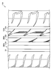
- FIG. 8 is a development view of a tread of the pneumatic tire 10X according to the comparative example.
- FIG. 9 is a tread development view of a pneumatic tire 10A according to a modified example of the present invention.
- FIG. 1 is a perspective view of a pneumatic tire 10 according to this embodiment.
- the pneumatic tire 10 is a tire that uses rubber having a low rolling resistance on the tread and is considered to save fuel in an automobile to which the pneumatic tire 10 is mounted.
- the pneumatic tire 10 may be filled with an inert gas such as nitrogen gas.
- the pneumatic tire 10 is provided with a plurality of land portions extending in the tire circumferential direction. Specifically, the pneumatic tire 10 is provided with a shoulder land portion 30, a shoulder land portion 40, a block-shaped land portion 100, and a rib-shaped land portion 200.
- the shoulder land portion 30 and the shoulder land portion 40 are respectively provided in the tread shoulder portion of the pneumatic tire 10.
- the block land portion 100 and the rib land portion 200 are provided between the shoulder land portion 30 and the shoulder land portion 40.
- a circumferential groove 21 extending in the tire circumferential direction is formed between the shoulder land portion 30 and the rib-shaped land portion 200.
- a circumferential groove 22 is formed between the block land portion 100 and the rib land portion 200, and a circumferential groove 23 is formed between the shoulder land portion 40 and the block land portion 100.
- the block land portion 100 is a portion surrounded by a one-dot chain line, and a plurality of block land portions 100 are provided along the tire circumferential direction.
- the “block-shaped land portion” is not limited to one in which individual land portions are clearly divided by lug grooves or the like, but by a sipe or narrow groove as in the block-shaped land portion 100 according to the present embodiment. Including those with individual land sections.
- the rib-like land portion 200 is a land portion that extends continuously along the tire circumferential direction and is longer than the block-like land portion 100.
- the rib-like land portion 200 does not necessarily have to be continuous along the tire circumferential direction, and may be divided by a narrow groove extending in the tread width direction as shown in FIG.
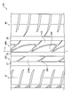
- FIG. 2 is a developed tread view of the pneumatic tire 10.
- FIG. 3 is a perspective view of the block-like land portion 100 and the rib-like land portion 200.
- the block land portion 100 includes a land portion 110 and a land portion 160.
- the land portion 110 is adjacent to the circumferential groove 23 and is located on the inner side in the tread width direction than the circumferential groove 23.
- the land portion 160 is adjacent to the land portion 110 and the circumferential groove 22 formed in the vicinity of the tire equator line CL.
- the land portion 160 is located on the inner side in the tread width direction than the land portion 110 with respect to the tire equator line CL.
- the land portion 110 constitutes a first land portion
- the land portion 160 constitutes a second land portion.
- the block-shaped land portion 100 is formed with an inclined groove 120 and an inclined groove 170.
- the inclined groove 120 has a wedge shape. Specifically, the inclined groove 120 has a deeper groove depth and a narrower groove width in the tire circumferential direction as it goes inward in the tread width direction. The inclined groove 120 extends obliquely toward the inner side in the tread width direction in a state adjacent to the land portion 110.
- the inclined groove 170 goes outward in the tread width direction, the groove depth becomes deeper and the groove width in the tire circumferential direction becomes narrower.
- the inclined groove 120 constitutes a first inclined groove
- the inclined groove 170 constitutes a second inclined groove.
- the side end 120a of the inclined groove 120 and the side end 170a of the inclined groove 170 are both arcuate in the tread surface view of the pneumatic tire 10, and the side end 120a and the side end 170a are formed so as to be smoothly connected. Is done.
- the end 121 on the inner side in the tread width direction of the inclined groove 120 extends toward the circumferential groove 22 along the end 161 in the tire circumferential direction of the land portion 160.
- the end 121 communicates with the circumferential groove 22.
- the end 122 of the inclined groove 120 on the outer side in the tread width direction is continuous with the land portion 110.
- an inter-block narrow groove 180 is formed between the block land portions 100 adjacent to each other.
- the inter-block narrow groove 180 extends in the tread width direction. Specifically, the inter-block narrow groove 180 communicates with an end 171 (one end) in the tire circumferential direction of the inclined groove 170. Further, the inter-block narrow groove 180 is adjacent to the inclined groove 120 of the adjacent block-shaped land portion 100.
- the sipe 190 is formed along the extending direction of the inter-block narrow groove 180.
- the sipe 190 is formed between the block land portions 100 adjacent to each other, like the inter-block narrow groove 180.
- the inter-block narrow groove 180 and the sipe 190 are formed on a straight line extending obliquely with respect to the tire circumferential direction. Further, the groove width of the sipe 190 is narrower than the inter-block narrow groove 180.
- the rib-shaped land portion 200 includes a land portion 210 and a rib narrow groove 260.
- a rib narrow groove 260 is formed between the land portions 210 adjacent to each other.
- the rib-like land portion 200 is adjacent to the circumferential groove 22 and extends in the tire circumferential direction substantially parallel to the block-like land portion 100 via the circumferential groove 22.
- the rib narrow groove 260 extends from one side end 210a of the rib-like land portion 200 to the other side end 210b. As a result, the rib-shaped land portion 200 is divided into a plurality of land portions 210.
- the extending direction of the rib narrow groove 260 is the same as that of the inter-block narrow groove 180. That is, the extending direction of the inter-block narrow grooves 180 is substantially the same as the extending direction of the rib narrow grooves 260 in the tread surface view of the pneumatic tire 10.
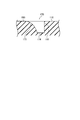
- FIG. 4 is a sectional view of the pneumatic tire 10 taken along line F4-F4 shown in FIG.
- FIG. 5 (a) is a cross-sectional view of the pneumatic tire 10 taken along line F5A-F5A shown in FIG. 2
- FIG. 5 (b) is an arrow view from the F5B direction shown in FIG. FIG.
- the inclined groove 170 is formed between the land portion 110 and the land portion 160. Specifically, the end 173 of the inclined groove 170 on the inner side in the tread width direction is continuous with the land portion 160.
- the inclined groove 170 extends along the end portion 111 of the land portion 110 on the inner side in the tread width direction.
- the inclined groove 170 is inclined so that the groove depth gradually increases from the land portion 160 toward the land portion 110, and the groove depth at the groove bottom 174 is the deepest.
- the inclined groove 120 is formed between the land portions 160 adjacent in the tire circumferential direction. Specifically, an inclined groove 120 and an interblock narrow groove 180 are formed between adjacent land portions 160.
- the inclined groove 120 is inclined so that the groove depth gradually increases toward the circumferential groove 22.
- the groove depth of the inter-block narrow groove 180 is deeper than the deepest portion of the inclined groove 120.
- the groove width W2 of the inclined groove 170 in the tire circumferential direction is wider than the groove width W1 of the inclined groove 120 in the tire circumferential direction. 2 and 3, when viewed from the tread surface of the pneumatic tire 10, the end 122 on the outer side in the tread width direction of the inclined groove 120 is the end 172 (the other end of the inclined groove 170 in the tire circumferential direction). Part). Further, as shown in FIG. 5B, the height H in the tire radial direction of the contact portion P between the inclined groove 120 and the inclined groove 170 is substantially the same as the tread surface T of the block-shaped land portion 100.
- FIG. 6 is a view as viewed from the direction F6 shown in FIG.
- FIG. 7 is a cross-sectional view of the pneumatic tire 10 taken along line F7-F7 shown in FIG.
- the protruding portion 211 located at one end of the land portion 210 in the tire circumferential direction is chamfered in an arc shape toward the groove bottom of the circumferential groove 21 in a side view of the land portion 210.
- an inclined surface 212 is formed on the other end of the land portion 210 in the tire circumferential direction.
- the inclined surface 212 is inclined toward the groove bottom of the circumferential groove 21.
- FIG. 8 is a development view of a tread of the pneumatic tire 10X according to the comparative example.
- the inclined groove 120 and the inclined groove 170 are not formed in the block-shaped land portion 100X of the pneumatic tire 10X according to the comparative example. Further, the land portion 210X is not formed with the protruding end portion 211 and the inclined surface 212.
- the pneumatic tire 10 according to the example is the tire described in the embodiment (see FIG. 1). That is, the inclined land 120 and the inclined groove 170 are formed in the block-shaped land portion 100. Further, the land portion 210 is formed with a protruding end portion 211 and an inclined surface 212.
- Hydroplaning evaluation A vehicle equipped with pneumatic tires is run at a speed of 80 km / h, and only the right wheel attached to the vehicle is accelerated by entering a rainy road with a depth of 10 mm. Hydroplaning occurs in the pneumatic tire 10 according to the embodiment, where the speed (hydroplaning generation speed) at which the speed difference (slip) between the left and right wheels mounted on the vehicle on which the pneumatic tire 10X according to the example is mounted is generated is 100. The speed was indexed. The larger the index, the better the drainage.
- the vehicle equipped with the pneumatic tire 10 according to the example has the same hydroplaning generation speed as the vehicle equipped with the pneumatic tire 10X according to the comparative example. It was found that the property (that is, wet performance) can be secured.
- the vehicle equipped with the pneumatic tire 10 according to the example is superior in steering stability on each of the dry road surface and the wet road surface as compared with the vehicle equipped with the pneumatic tire 10X according to the comparative example. I understood.
- the rigidity of the block-shaped land portion 100 can be improved while ensuring drainage in the block-shaped land portion 100. That is, according to the pneumatic tire 10, it is possible to achieve both wet performance and steering stability at a higher level. Further, since the block-like land portion 100 is located on the outer side in the tread width direction than the circumferential groove 22 when the vehicle is mounted, the block-like land portion 100 is placed closer to the outer side in the tread width direction that has a great influence on the steering stability during cornering. Can be positioned. That is, according to the pneumatic tire 10, the steering stability at the time of cornering can be improved.
- the end 121 of the inclined groove 120 on the inner side in the tread width direction communicates with the circumferential groove 22.
- the groove width W2 of the inclined groove 170 is wider than the groove width W1 of the inclined groove 120. For this reason, drainage in the tire circumferential direction can be further improved using the inclined groove 170 while draining from the inclined groove 120 to the circumferential groove 22.
- the height H of the contact portion P between the inclined groove 120 and the inclined groove 170 is substantially the same as the tread surface T. For this reason, compared with the case where the inclined groove 120 and the inclined groove 170 are separately formed in the block-shaped land part 100, the rigidity of the block-shaped land part 100 improves.
- the inter-block narrow groove 180 communicates with the end 171 of the inclined groove 170 and is adjacent to the inclined groove 120. For this reason, the drainage property in the block-like land portion 100 can be further improved.
- the extending direction of the inter-block narrow grooves 180 is substantially the same as the extending direction of the rib thin grooves 260. For this reason, it can contribute to the smooth drainage via the inter-block narrow groove 180 and the rib narrow groove 260. That is, according to the pneumatic tire 10, the steering stability can be further improved while ensuring the wet performance.
- the projecting end portion 211 of the land portion 210 is chamfered in an arc shape in a side view of the land portion 210. Furthermore, in the land part 210. An inclined surface 212 that is inclined toward the groove bottom of the circumferential groove 21 is formed. For this reason, it can suppress that the edge part of the tire circumferential direction of the land part 210 becomes the nucleus of partial wear.
- FIG. 9 is a tread development view of a pneumatic tire 10A according to a modified example of the present invention.
- circumferential grooves 21A to 23A and a circumferential groove 24 are formed in the pneumatic tire 10A.
- the block land portion 100A is formed between the circumferential groove 22A and the circumferential groove 23A.
- the rib-shaped land portion 200A is formed between the circumferential groove 21A and the circumferential groove 22A.
- the block-like land portion 100A and the rib-like land portion 200A have the same shape as the block-like land portion 100 and the rib-like land portion 200 described above.
- the pneumatic tire 10A is further provided with a rib land portion 300A.
- the rib land portion 300A is a land portion having a simple shape in which no rib narrow groove or the like is formed.
- the pneumatic tire 10 ⁇ / b> A can achieve the same effects as the pneumatic tire 10.
- the pneumatic tire 10 is a tire in consideration of fuel efficiency using rubber with low rolling resistance, but the scope of application of the present invention is not limited to a tire with low rolling resistance. Furthermore, the application range of the present invention is not limited to the pneumatic tire, and the tread pattern as described above may be adopted for the solid tire.
Landscapes
- Engineering & Computer Science (AREA)
- Mechanical Engineering (AREA)
- Tires In General (AREA)
Abstract
Description
図1は、本実施形態に係る空気入りタイヤ10の斜視図である。空気入りタイヤ10は、トレッドに転がり抵抗の低いゴムが用いられ、空気入りタイヤ10が装着される自動車の省燃費に配慮されたタイヤである。なお、空気入りタイヤ10には、窒素ガスなどの不活性ガスを充填してもよい。
図2は、空気入りタイヤ10のトレッド展開図である。図3は、ブロック状陸部100及びリブ状陸部200の斜視図である。
ブロック状陸部100は、陸部110及び陸部160を含む。陸部110は、周方向溝23に隣接し、周方向溝23よりもトレッド幅方向内側に位置する。陸部160は、陸部110及びタイヤ赤道線CL近傍に形成された周方向溝22に隣接する。陸部160は、タイヤ赤道線CLを基準として、陸部110よりもトレッド幅方向内側に位置する。本実施形態において、陸部110は第1陸部を構成し、陸部160は第2陸部を構成する。
リブ状陸部200は、陸部210及びリブ細溝260を含む。互いに隣接する陸部210の間には、リブ細溝260が形成される。リブ状陸部200は、周方向溝22に隣接するとともに、周方向溝22を介してブロック状陸部100と略平行にタイヤ周方向に延びる。
図4は、図2に示したF4-F4線に沿った空気入りタイヤ10の断面図である。同様に、図5(a)は、図2に示したF5A-F5A線に沿った空気入りタイヤ10の断面図であり、図5(b)は、図2に示したF5B方向からの矢視図である。
図4に示すように、傾斜溝170は、陸部110と陸部160との間に形成される。具体的には、傾斜溝170のトレッド幅方向内側の端部173は、陸部160に連なる。また、傾斜溝170は、陸部110のトレッド幅方向内側の端部111に沿って延在する。傾斜溝170は、陸部160から陸部110に向かって徐々に溝深さが深くなるように傾斜しており、溝底174における溝深さが最も深い。
図5(a)及び(b)に示すように、傾斜溝120は、タイヤ周方向において隣接する陸部160の間に形成される。具体的には、隣接する陸部160の間には、傾斜溝120とブロック間細溝180が形成される。傾斜溝120は、周方向溝22に向かって徐々に溝深さが深くなるように傾斜している。ブロック間細溝180の溝深さは、傾斜溝120の最深部よりも深い。
図2に示すように、傾斜溝170のタイヤ周方向における溝幅W2は、傾斜溝120のタイヤ周方向における溝幅W1よりも広い。また、図2及び図3に示すように、空気入りタイヤ10のトレッド面視において、傾斜溝120のトレッド幅方向外側の端部122は、傾斜溝170のタイヤ周方向における端部172(他端部)と接している。さらに、図5(b)に示すように、傾斜溝120と傾斜溝170との接点部分Pのタイヤ径方向における高さHは、ブロック状陸部100の踏面Tと略同一である。
図6は、図2に示したF6方向からの矢視図である。図7は、図2に示したF7-F7線に沿った空気入りタイヤ10の断面図である。図6に示すように、陸部210のタイヤ周方向における一端に位置する突端部分211は、陸部210の側面視において、周方向溝21の溝底に向かって円弧状に面取りされている。
次に、本発明の効果をさらに明確にするために、以下の比較例及び実施例に係る空気入りタイヤを用いて行った比較評価について説明する。具体的には、(5.1)各空気入りタイヤの構成、(5.2)評価結果について説明する。なお、本発明はこれらの例によって何ら限定されるものではない。
まず、各空気入りタイヤの構成について、図面を参照しながら簡単に説明する。図8は、比較例に係る空気入りタイヤ10Xのトレッド展開図である。
次に、各空気入りタイヤを用いて行った評価結果について、表1を参照しながら説明する。具体的には、(5.2.1)ハイドロプレーニング評価、(5.2.2)操縦安定性評価について説明する。

各空気入りタイヤを装着した車両を速度80km/hで走行させ、当該車両に装着された右輪のみを水深10mmの雨路に進入させて加速し、比較例に係る空気入りタイヤ10Xが装着された車両に装着された左右両輪の速度差(スリップ)が発生した速度(ハイドロプレーニング発生速度)を100とし、実施例に係る空気入りタイヤ10のハイドロプレーニング発生速度を指数化した。なお、指数が大きいほど、排水性に優れている。
ドライ路面及びウェット路面のそれぞれのテストコースにおいて、比較例に係る空気入りタイヤ10Xが装着された車両の操縦安定性(直進時やコーナリング時等)を‘100’とし、実施例に係る空気入りタイヤ10が装着された車両の操縦安定性をプロドライバーによりフィーリング評価した。なお、指数が大きいほど、操縦安定性に優れている。
空気入りタイヤ10によれば、空気入りタイヤ10が車両に装着された場合に周方向溝22よりもトレッド幅方向外側に位置するブロック状陸部100に、傾斜溝120と傾斜溝170とが形成される。傾斜溝120と傾斜溝170とは、トレッド幅方向において異なる位置に設けられる。さらに、傾斜溝120の延在方向と傾斜溝170の延在方向、すなわち、傾斜溝120の傾斜方向と傾斜溝170の傾斜方向とは異なる。
上述したように、本発明の実施形態を通じて本発明の内容を開示したが、この開示の一部をなす論述及び図面は、本発明を限定するものであると理解すべきではない。この開示から当業者には様々な代替実施の形態、実施例及び運用技術が明らかとなる。
Claims (7)
- タイヤ周方向に延びる周方向溝が形成され、
前記周方向溝よりもトレッド幅方向外側において、タイヤ周方向に沿って複数のブロック状陸部が設けられたタイヤであって、
トレッド幅方向内側に向かうに連れて、溝深さが深くなるとともにタイヤ周方向における溝幅が狭くなる第1傾斜溝と、
トレッド幅方向外側に向かうに連れて、溝深さが深くなるとともにタイヤ周方向における溝幅が狭くなる第2傾斜溝と
が形成され、
前記ブロック状陸部は、
第1陸部と、
前記第1陸部に隣接し、前記第1陸部よりもトレッド幅方向内側に位置する第2陸部と
を有し、
前記第1傾斜溝のトレッド幅方向外側の端部は、前記第1陸部に連なるとともに、前記第1傾斜溝のトレッド幅方向内側の端部は、前記第2陸部のタイヤ周方向における端部に沿って前記周方向溝に向けて延在し、
前記第2傾斜溝のトレッド幅方向内側の端部は、前記第2陸部に連なるとともに、前記第2傾斜溝は、前記第1陸部のトレッド幅方向内側の端部に沿って延在するタイヤ。 - 前記第1傾斜溝のトレッド幅方向内側の端部は、前記周方向溝に連通する請求項1に記載のタイヤ。
- 前記第2傾斜溝のタイヤ周方向における溝幅は、前記第1傾斜溝のタイヤ周方向における溝幅よりも広い請求項1または2に記載のタイヤ。
- 互いに隣接する前記ブロック状陸部の間には、トレッド幅方向に延びるブロック間細溝が形成され、
前記ブロック間細溝は、前記第2傾斜溝のタイヤ周方向における一端部に連通する請求項3に記載のタイヤ。 - 前記ブロック間細溝は、前記第1傾斜溝と隣接する請求項4に記載のタイヤ。
- 前記タイヤのトレッド面視において、前記第1傾斜溝のトレッド幅方向外側の端部は、前記第2傾斜溝のタイヤ周方向における他端部と接し、
前記第1傾斜溝のトレッド幅方向外側の端部と、前記第2傾斜溝のタイヤ周方向における他端部とが接する接点部分のタイヤ径方向における高さは、前記ブロック状陸部の踏面と略同一である請求項4または5に記載のタイヤ。 - 前記周方向溝に隣接するとともに、前記周方向溝を介して前記ブロック状陸部と略平行にタイヤ周方向に延びるリブ状陸部が設けられ、
前記リブ状陸部には、前記リブ状陸部の一方の側端から他方の側端まで延びるリブ細溝が形成され、
前記タイヤのトレッド面視において、前記ブロック間細溝の延在方向は、前記リブ細溝の延在方向と略同一である請求項4乃至6の何れか一項に記載のタイヤ。
Priority Applications (3)
| Application Number | Priority Date | Filing Date | Title |
|---|---|---|---|
| US13/575,836 US9358843B2 (en) | 2010-01-29 | 2011-01-28 | Tire |
| CN201180007483.2A CN102725153B (zh) | 2010-01-29 | 2011-01-28 | 轮胎 |
| EP11737162.5A EP2529953B1 (en) | 2010-01-29 | 2011-01-28 | Tyre |
Applications Claiming Priority (2)
| Application Number | Priority Date | Filing Date | Title |
|---|---|---|---|
| JP2010-019171 | 2010-01-29 | ||
| JP2010019171A JP5478284B2 (ja) | 2010-01-29 | 2010-01-29 | タイヤ |
Publications (1)
| Publication Number | Publication Date |
|---|---|
| WO2011093452A1 true WO2011093452A1 (ja) | 2011-08-04 |
Family
ID=44319432
Family Applications (1)
| Application Number | Title | Priority Date | Filing Date |
|---|---|---|---|
| PCT/JP2011/051758 WO2011093452A1 (ja) | 2010-01-29 | 2011-01-28 | タイヤ |
Country Status (5)
| Country | Link |
|---|---|
| US (1) | US9358843B2 (ja) |
| EP (1) | EP2529953B1 (ja) |
| JP (1) | JP5478284B2 (ja) |
| CN (1) | CN102725153B (ja) |
| WO (1) | WO2011093452A1 (ja) |
Cited By (2)
| Publication number | Priority date | Publication date | Assignee | Title |
|---|---|---|---|---|
| JP2013035316A (ja) * | 2011-08-03 | 2013-02-21 | Bridgestone Corp | タイヤ |
| CN104010834A (zh) * | 2011-12-27 | 2014-08-27 | 株式会社普利司通 | 充气轮胎 |
Families Citing this family (5)
| Publication number | Priority date | Publication date | Assignee | Title |
|---|---|---|---|---|
| JP5977696B2 (ja) | 2013-03-13 | 2016-08-24 | 株式会社ブリヂストン | 空気入りタイヤ |
| JP6282865B2 (ja) | 2014-01-15 | 2018-02-21 | 株式会社ブリヂストン | タイヤ |
| JP6052227B2 (ja) * | 2014-05-12 | 2016-12-27 | 横浜ゴム株式会社 | 更生タイヤ |
| JP6405284B2 (ja) * | 2015-04-17 | 2018-10-17 | 住友ゴム工業株式会社 | 空気入りタイヤ |
| CN107667017B (zh) * | 2015-06-12 | 2019-10-25 | 株式会社普利司通 | 轮胎胎面 |
Citations (6)
| Publication number | Priority date | Publication date | Assignee | Title |
|---|---|---|---|---|
| JP2003326918A (ja) * | 2002-05-13 | 2003-11-19 | Bridgestone Corp | 空気入りタイヤ |
| JP2006274049A (ja) | 2005-03-29 | 2006-10-12 | Bridgestone Corp | ゴム組成物及びそれを用いた空気入りタイヤ |
| JP2008149995A (ja) * | 2006-12-20 | 2008-07-03 | Bridgestone Corp | 空気入りタイヤ |
| JP2008201379A (ja) | 2007-02-22 | 2008-09-04 | Bridgestone Corp | タイヤ |
| WO2008126551A1 (ja) * | 2007-03-14 | 2008-10-23 | Bridgestone Corporation | 空気入りタイヤ |
| JP2010019171A (ja) | 2008-07-10 | 2010-01-28 | Toyota Motor Corp | 内燃機関の排気浄化装置 |
Family Cites Families (9)
| Publication number | Priority date | Publication date | Assignee | Title |
|---|---|---|---|---|
| JP3590137B2 (ja) * | 1995-06-19 | 2004-11-17 | 株式会社ブリヂストン | 方向性傾斜ブロックを有する高運動性能空気入りタイヤ |
| JP3367927B2 (ja) | 2000-01-24 | 2003-01-20 | 住友ゴム工業株式会社 | 空気入りタイヤ |
| CN2445952Y (zh) * | 2000-03-23 | 2001-09-05 | 广州市华南橡胶轮胎有限公司 | 充气乘用子午线轮胎胎面花纹 |
| JP4420598B2 (ja) * | 2001-10-18 | 2010-02-24 | 株式会社ブリヂストン | 空気入りタイヤ |
| JP4065718B2 (ja) * | 2002-05-09 | 2008-03-26 | 株式会社ブリヂストン | 空気入りタイヤ |
| CN100509448C (zh) | 2002-11-06 | 2009-07-08 | 株式会社普利司通 | 充气轮胎 |
| WO2007145177A1 (ja) * | 2006-06-12 | 2007-12-21 | The Yokohama Rubber Co., Ltd. | 空気入りタイヤ |
| WO2008075630A1 (ja) | 2006-12-20 | 2008-06-26 | Bridgestone Corporation | 空気入りタイヤ |
| US9254719B2 (en) * | 2008-12-10 | 2016-02-09 | Pirelli Tyre S.P.A. | Pneumatic tire |
-
2010
- 2010-01-29 JP JP2010019171A patent/JP5478284B2/ja not_active Expired - Fee Related
-
2011
- 2011-01-28 WO PCT/JP2011/051758 patent/WO2011093452A1/ja active Application Filing
- 2011-01-28 EP EP11737162.5A patent/EP2529953B1/en not_active Not-in-force
- 2011-01-28 CN CN201180007483.2A patent/CN102725153B/zh not_active Expired - Fee Related
- 2011-01-28 US US13/575,836 patent/US9358843B2/en active Active
Patent Citations (6)
| Publication number | Priority date | Publication date | Assignee | Title |
|---|---|---|---|---|
| JP2003326918A (ja) * | 2002-05-13 | 2003-11-19 | Bridgestone Corp | 空気入りタイヤ |
| JP2006274049A (ja) | 2005-03-29 | 2006-10-12 | Bridgestone Corp | ゴム組成物及びそれを用いた空気入りタイヤ |
| JP2008149995A (ja) * | 2006-12-20 | 2008-07-03 | Bridgestone Corp | 空気入りタイヤ |
| JP2008201379A (ja) | 2007-02-22 | 2008-09-04 | Bridgestone Corp | タイヤ |
| WO2008126551A1 (ja) * | 2007-03-14 | 2008-10-23 | Bridgestone Corporation | 空気入りタイヤ |
| JP2010019171A (ja) | 2008-07-10 | 2010-01-28 | Toyota Motor Corp | 内燃機関の排気浄化装置 |
Non-Patent Citations (1)
| Title |
|---|
| See also references of EP2529953A4 |
Cited By (4)
| Publication number | Priority date | Publication date | Assignee | Title |
|---|---|---|---|---|
| JP2013035316A (ja) * | 2011-08-03 | 2013-02-21 | Bridgestone Corp | タイヤ |
| CN104010834A (zh) * | 2011-12-27 | 2014-08-27 | 株式会社普利司通 | 充气轮胎 |
| CN104010834B (zh) * | 2011-12-27 | 2016-06-29 | 株式会社普利司通 | 充气轮胎 |
| US10252576B2 (en) | 2011-12-27 | 2019-04-09 | Bridgestone Corporation | Pneumatic tire |
Also Published As
| Publication number | Publication date |
|---|---|
| CN102725153B (zh) | 2015-02-04 |
| EP2529953A1 (en) | 2012-12-05 |
| US20130020002A1 (en) | 2013-01-24 |
| EP2529953A4 (en) | 2015-04-08 |
| EP2529953B1 (en) | 2017-06-21 |
| JP5478284B2 (ja) | 2014-04-23 |
| JP2011156941A (ja) | 2011-08-18 |
| US9358843B2 (en) | 2016-06-07 |
| CN102725153A (zh) | 2012-10-10 |
Similar Documents
| Publication | Publication Date | Title |
|---|---|---|
| AU2010207199B2 (en) | Tire | |
| JP4769858B2 (ja) | 空気入りタイヤ | |
| JP5294735B2 (ja) | 空気入りタイヤ | |
| WO2011093452A1 (ja) | タイヤ | |
| US20150231929A1 (en) | Pneumatic tire | |
| US9358842B2 (en) | Tire | |
| JP5687446B2 (ja) | タイヤ | |
| US9027614B2 (en) | Heavy duty pneumatic tire | |
| US20130000804A1 (en) | Tire | |
| US9033012B2 (en) | Tire having a circumferential groove including a first groove portion and a second groove portion | |
| JP2009006877A (ja) | 重荷重タイヤ | |
| WO2013015408A1 (ja) | タイヤ | |
| JP2011088498A (ja) | タイヤ | |
| WO2011102264A1 (ja) | タイヤ | |
| JP2006298060A (ja) | 空気入りラジアルタイヤ | |
| JP5357662B2 (ja) | タイヤ | |
| JP4421432B2 (ja) | 空気入りタイヤ | |
| JP5766541B2 (ja) | タイヤ | |
| JP2011201337A (ja) | タイヤ | |
| JP2010254154A (ja) | タイヤ | |
| WO2021054261A1 (ja) | タイヤ | |
| JP2011143795A (ja) | 空気入りタイヤ | |
| JP5626954B2 (ja) | タイヤ | |
| JP2006297980A (ja) | 空気入りラジアルタイヤ | |
| US20210260927A1 (en) | Tire |
Legal Events
| Date | Code | Title | Description |
|---|---|---|---|
| WWE | Wipo information: entry into national phase |
Ref document number: 201180007483.2 Country of ref document: CN |
|
| 121 | Ep: the epo has been informed by wipo that ep was designated in this application |
Ref document number: 11737162 Country of ref document: EP Kind code of ref document: A1 |
|
| DPE1 | Request for preliminary examination filed after expiration of 19th month from priority date (pct application filed from 20040101) | ||
| WWE | Wipo information: entry into national phase |
Ref document number: 1201003836 Country of ref document: TH |
|
| NENP | Non-entry into the national phase |
Ref country code: DE |
|
| REEP | Request for entry into the european phase |
Ref document number: 2011737162 Country of ref document: EP |
|
| WWE | Wipo information: entry into national phase |
Ref document number: 2011737162 Country of ref document: EP |
|
| WWE | Wipo information: entry into national phase |
Ref document number: 13575836 Country of ref document: US |