WO2011086899A1 - 電力供給装置および車両充電システム - Google Patents
電力供給装置および車両充電システム Download PDFInfo
- Publication number
- WO2011086899A1 WO2011086899A1 PCT/JP2011/000095 JP2011000095W WO2011086899A1 WO 2011086899 A1 WO2011086899 A1 WO 2011086899A1 JP 2011000095 W JP2011000095 W JP 2011000095W WO 2011086899 A1 WO2011086899 A1 WO 2011086899A1
- Authority
- WO
- WIPO (PCT)
- Prior art keywords
- power line
- signal
- line communication
- vehicle
- unit
- Prior art date
Links
Images


Classifications
-
- H—ELECTRICITY
- H04—ELECTRIC COMMUNICATION TECHNIQUE
- H04B—TRANSMISSION
- H04B3/00—Line transmission systems
- H04B3/54—Systems for transmission via power distribution lines
- H04B3/542—Systems for transmission via power distribution lines the information being in digital form
-
- B—PERFORMING OPERATIONS; TRANSPORTING
- B60—VEHICLES IN GENERAL
- B60L—PROPULSION OF ELECTRICALLY-PROPELLED VEHICLES; SUPPLYING ELECTRIC POWER FOR AUXILIARY EQUIPMENT OF ELECTRICALLY-PROPELLED VEHICLES; ELECTRODYNAMIC BRAKE SYSTEMS FOR VEHICLES IN GENERAL; MAGNETIC SUSPENSION OR LEVITATION FOR VEHICLES; MONITORING OPERATING VARIABLES OF ELECTRICALLY-PROPELLED VEHICLES; ELECTRIC SAFETY DEVICES FOR ELECTRICALLY-PROPELLED VEHICLES
- B60L53/00—Methods of charging batteries, specially adapted for electric vehicles; Charging stations or on-board charging equipment therefor; Exchange of energy storage elements in electric vehicles
- B60L53/60—Monitoring or controlling charging stations
-
- B—PERFORMING OPERATIONS; TRANSPORTING
- B60—VEHICLES IN GENERAL
- B60L—PROPULSION OF ELECTRICALLY-PROPELLED VEHICLES; SUPPLYING ELECTRIC POWER FOR AUXILIARY EQUIPMENT OF ELECTRICALLY-PROPELLED VEHICLES; ELECTRODYNAMIC BRAKE SYSTEMS FOR VEHICLES IN GENERAL; MAGNETIC SUSPENSION OR LEVITATION FOR VEHICLES; MONITORING OPERATING VARIABLES OF ELECTRICALLY-PROPELLED VEHICLES; ELECTRIC SAFETY DEVICES FOR ELECTRICALLY-PROPELLED VEHICLES
- B60L2270/00—Problem solutions or means not otherwise provided for
- B60L2270/10—Emission reduction
- B60L2270/14—Emission reduction of noise
- B60L2270/147—Emission reduction of noise electro magnetic [EMI]
-
- H—ELECTRICITY
- H04—ELECTRIC COMMUNICATION TECHNIQUE
- H04B—TRANSMISSION
- H04B2203/00—Indexing scheme relating to line transmission systems
- H04B2203/54—Aspects of powerline communications not already covered by H04B3/54 and its subgroups
- H04B2203/5429—Applications for powerline communications
- H04B2203/5445—Local network
-
- H—ELECTRICITY
- H04—ELECTRIC COMMUNICATION TECHNIQUE
- H04B—TRANSMISSION
- H04B2203/00—Indexing scheme relating to line transmission systems
- H04B2203/54—Aspects of powerline communications not already covered by H04B3/54 and its subgroups
- H04B2203/5429—Applications for powerline communications
- H04B2203/5458—Monitor sensor; Alarm systems
-
- H—ELECTRICITY
- H04—ELECTRIC COMMUNICATION TECHNIQUE
- H04B—TRANSMISSION
- H04B2203/00—Indexing scheme relating to line transmission systems
- H04B2203/54—Aspects of powerline communications not already covered by H04B3/54 and its subgroups
- H04B2203/5462—Systems for power line communications
- H04B2203/5483—Systems for power line communications using coupling circuits
-
- H—ELECTRICITY
- H04—ELECTRIC COMMUNICATION TECHNIQUE
- H04B—TRANSMISSION
- H04B3/00—Line transmission systems
- H04B3/54—Systems for transmission via power distribution lines
-
- Y—GENERAL TAGGING OF NEW TECHNOLOGICAL DEVELOPMENTS; GENERAL TAGGING OF CROSS-SECTIONAL TECHNOLOGIES SPANNING OVER SEVERAL SECTIONS OF THE IPC; TECHNICAL SUBJECTS COVERED BY FORMER USPC CROSS-REFERENCE ART COLLECTIONS [XRACs] AND DIGESTS
- Y02—TECHNOLOGIES OR APPLICATIONS FOR MITIGATION OR ADAPTATION AGAINST CLIMATE CHANGE
- Y02T—CLIMATE CHANGE MITIGATION TECHNOLOGIES RELATED TO TRANSPORTATION
- Y02T10/00—Road transport of goods or passengers
- Y02T10/60—Other road transportation technologies with climate change mitigation effect
- Y02T10/70—Energy storage systems for electromobility, e.g. batteries
-
- Y—GENERAL TAGGING OF NEW TECHNOLOGICAL DEVELOPMENTS; GENERAL TAGGING OF CROSS-SECTIONAL TECHNOLOGIES SPANNING OVER SEVERAL SECTIONS OF THE IPC; TECHNICAL SUBJECTS COVERED BY FORMER USPC CROSS-REFERENCE ART COLLECTIONS [XRACs] AND DIGESTS
- Y02—TECHNOLOGIES OR APPLICATIONS FOR MITIGATION OR ADAPTATION AGAINST CLIMATE CHANGE
- Y02T—CLIMATE CHANGE MITIGATION TECHNOLOGIES RELATED TO TRANSPORTATION
- Y02T10/00—Road transport of goods or passengers
- Y02T10/60—Other road transportation technologies with climate change mitigation effect
- Y02T10/7072—Electromobility specific charging systems or methods for batteries, ultracapacitors, supercapacitors or double-layer capacitors
-
- Y—GENERAL TAGGING OF NEW TECHNOLOGICAL DEVELOPMENTS; GENERAL TAGGING OF CROSS-SECTIONAL TECHNOLOGIES SPANNING OVER SEVERAL SECTIONS OF THE IPC; TECHNICAL SUBJECTS COVERED BY FORMER USPC CROSS-REFERENCE ART COLLECTIONS [XRACs] AND DIGESTS
- Y02—TECHNOLOGIES OR APPLICATIONS FOR MITIGATION OR ADAPTATION AGAINST CLIMATE CHANGE
- Y02T—CLIMATE CHANGE MITIGATION TECHNOLOGIES RELATED TO TRANSPORTATION
- Y02T90/00—Enabling technologies or technologies with a potential or indirect contribution to GHG emissions mitigation
- Y02T90/10—Technologies relating to charging of electric vehicles
- Y02T90/12—Electric charging stations
-
- Y—GENERAL TAGGING OF NEW TECHNOLOGICAL DEVELOPMENTS; GENERAL TAGGING OF CROSS-SECTIONAL TECHNOLOGIES SPANNING OVER SEVERAL SECTIONS OF THE IPC; TECHNICAL SUBJECTS COVERED BY FORMER USPC CROSS-REFERENCE ART COLLECTIONS [XRACs] AND DIGESTS
- Y02—TECHNOLOGIES OR APPLICATIONS FOR MITIGATION OR ADAPTATION AGAINST CLIMATE CHANGE
- Y02T—CLIMATE CHANGE MITIGATION TECHNOLOGIES RELATED TO TRANSPORTATION
- Y02T90/00—Enabling technologies or technologies with a potential or indirect contribution to GHG emissions mitigation
- Y02T90/10—Technologies relating to charging of electric vehicles
- Y02T90/14—Plug-in electric vehicles
-
- Y—GENERAL TAGGING OF NEW TECHNOLOGICAL DEVELOPMENTS; GENERAL TAGGING OF CROSS-SECTIONAL TECHNOLOGIES SPANNING OVER SEVERAL SECTIONS OF THE IPC; TECHNICAL SUBJECTS COVERED BY FORMER USPC CROSS-REFERENCE ART COLLECTIONS [XRACs] AND DIGESTS
- Y02—TECHNOLOGIES OR APPLICATIONS FOR MITIGATION OR ADAPTATION AGAINST CLIMATE CHANGE
- Y02T—CLIMATE CHANGE MITIGATION TECHNOLOGIES RELATED TO TRANSPORTATION
- Y02T90/00—Enabling technologies or technologies with a potential or indirect contribution to GHG emissions mitigation
- Y02T90/10—Technologies relating to charging of electric vehicles
- Y02T90/16—Information or communication technologies improving the operation of electric vehicles
Definitions
- the present invention relates to a power supply device that includes a power storage device and a motor that rotates a wheel and supplies power to a vehicle that drives the motor using the power of the power storage device, and a vehicle charging system that uses the power supply device.
- the charging device for a vehicle is connected to a power line of a power source in the house and supplies the power for charging to the vehicle using the power of the power source in the house.
- the charging instruction device in the house superimposes a high-frequency signal on the power line and performs power line communication with the vehicle via the vehicle charging device, the high-frequency signal of the power line communication output from the charging instruction device passes through the power line. There was a problem that it was easy to leak outside.
- an object of the present invention is to make it difficult for a high-frequency signal of power line communication to leak out of the house even when the charge instruction device in the house performs power line communication with the vehicle via the vehicle charging device.
- a power supply device is a power supply device that supplies power to a device having a second power line communication device that communicates with the first power line communication device via a power line.
- a receiving unit that receives the first signal transmitted from the first power line communication device and having the first frequency via the power line; and the first signal is lower than the first frequency.
- a configuration is adopted that includes a frequency conversion unit that converts a second signal having a second frequency and a transmission unit that transmits the second signal to the second power line communication device via the power line.
- the first power line communication device is configured by converting the first signal having the first frequency into the second signal having a frequency lower than the first frequency and transmitting the converted signal to the device. In power line communication between the device and the device, signal leakage can be reduced.
- the power supply apparatus employs a configuration in which the first signal includes control information related to power supply performed by the power supply apparatus.
- the power supply apparatus employs a configuration in which the first signal includes information related to authentication for authenticating the device.
- a power supply device includes: a connection unit that disconnects or connects the power line; and the connection unit based on at least one of the first signal and the second signal. And a control unit for controlling.
- the power supply device further includes a blocking unit that allows the power to pass through and blocks the first signal, and a bypass unit that bypasses the blocking unit and the connection unit.
- a blocking unit that allows the power to pass through and blocks the first signal
- a bypass unit that bypasses the blocking unit and the connection unit.
- the first signal and the second signal can be transmitted even when the power line is disconnected. That is, it becomes possible to independently supply power to the device and transmit the first signal and the second signal.
- the power supply device employs a configuration in which the blocking unit is a low-pass filter.
- the power supply device employs a configuration in which the low-pass filter is a T-type filter, a ⁇ -type filter, or an L-type filter composed of an inductor and a capacitor.
- the power supply device is directed to a charge permission for allowing the first power line communication device to charge the device according to the first signal when authentication with the device is successful.
- the information is stored, and the control unit adopts a configuration for controlling the connection unit so that the power line is connected based on the charge permission information.
- connection unit since the connection unit is controlled so that the power line is connected based on the charging permission information stored in the first signal, charging the device only when the device is successfully authenticated. It is possible to prevent theft and the like.
- the first power line communication device may not be charged without permitting charging of the device in the first signal when authentication with the device fails.
- the permission information is stored, and the control unit controls the connection unit based on the charging non-permission information so that the power line is disconnected.
- connection unit since the connection unit is controlled so that the power line is disconnected based on the charging non-permission information stored in the first signal, if the device authentication fails, the device is charged. Therefore, it is possible to prevent power theft.
- the first signal is a first multicarrier signal using a first frequency band
- the second signal is the first frequency.
- a second multicarrier signal using a second frequency band that is narrower than the band, and the frequency converter has a destination of the first multicarrier signal received by the receiver different from that of the power supply apparatus The first multicarrier signal is not converted to the second multicarrier signal.
- the second multicarrier signal When the destination of the first multicarrier signal is different from that of the power supply apparatus, when the first multicarrier signal is converted to the second multicarrier signal, the second multicarrier signal is relatively narrow compared to the first frequency band. The frequency band is wasted. Therefore, according to this configuration, since the frequency conversion unit does not perform conversion into the second multicarrier signal in such a case, the second frequency band can be effectively used.
- the first signal is a first multicarrier signal using a first frequency band
- the second signal is the first frequency.
- a second multicarrier signal using a second frequency band that is narrower than the band, and the frequency converter is configured such that the destination of the first multicarrier signal received by the receiver is the second power line communication device.
- the first multicarrier signal is not converted into the second multicarrier signal.
- the first multicarrier signal When the destination of the first multicarrier signal is different from that of the second power line communication device, when the first multicarrier signal is converted into the second multicarrier signal, the first multicarrier signal is relatively compared to the first frequency band. The narrow second frequency band is wasted. Therefore, according to this configuration, since the frequency conversion unit does not perform conversion into the second multicarrier signal in such a case, the second frequency band can be effectively used.
- a vehicle charging system employs a configuration having any one of the power supply devices described above, the first power line communication device, and a vehicle including the second power line communication device.
- the leakage of the power line communication signal can be reduced in the power line signal between the first power line communication device and the vehicle that is performed during authentication or during charging.
- the high frequency signal of the power line communication output from the charging instruction device and superimposed on the home power line is attenuated by the low-pass filter and then output to the power line for the vehicle. can do.
- the power line communication unit converts the signal into a signal having a frequency lower than the high frequency signal of the power line communication used in the house and communicates with the vehicle outside the house, the power line communication signal can be made difficult to leak outside the house. .
- the charging instruction device in the house since the electric power from the home power line is supplied to the vehicle based on the instruction of the charging instruction device, the charging instruction device in the house performs power line communication with the vehicle via the vehicle charging device. Even so, it is possible to make it difficult to leak power line communication signals.
- Configuration diagram of a vehicle charging system in an embodiment of the present invention The block diagram which shows the structure of the charging device for vehicles of the vehicle charging system
- the block diagram which shows the structure of the 1st power line communication part of the charging device for vehicles in the vehicle charging system.
- the block diagram which shows the structure of the low-pass filter of the charging device for vehicles in the vehicle charging system
- the block diagram which shows the other structural example of the low-pass filter of the charging device for vehicles in the vehicle charging system The block diagram which shows the further another structural example of the low-pass filter of the charging device for vehicles in the vehicle charging system Flow chart explaining operation of the vehicle charging system
- a vehicle charging system according to an embodiment of the present invention will be described with reference to FIGS.
- the electric power stored in the power storage device can be supplied to a motor, and the wheel can be rotated by the motor to move to another place.
- FIG. 1 is a configuration diagram of a vehicle charging system 1 according to an embodiment of the present invention.
- a vehicle charging system 1 includes a charging instruction device 5 having a built-in power line communication unit 4, a vehicle charging device 6, and a vehicle 8 connected to the vehicle charging device 6 via a vehicle power line 7. And.
- the charging instruction device 5 and the vehicle charging device 6 are connected to the power source 3 of the house 2. Thereby, the electric power required for the vehicle charging device 6 is supplied from the power source 3 of the house 2.
- the vehicle charging device 6 supplies power to the vehicle 8 using the power of the power source 3 of the house 2.
- the vehicle 8 is authenticated by the charging instruction device 5, and power is supplied to the vehicle 8 only when authentication is possible.
- the vehicle 8 charges the power supplied through the power supply port 9 to the power storage device 10 mounted on the vehicle main body 8a.
- the charging instruction device 5 is composed of a dedicated machine. A personal computer may be used instead of the dedicated machine.
- the charging instruction device 5 performs power line communication with the vehicle charging device 6 using the power line of the power source 3 via the built-in power line communication unit 4.
- the vehicle charging device 6 is connected to the in-house power line 3a of the power source 3 in the house 2 and supplies the vehicle 8 with charging power using the power of the power source 3 in the house 2.
- the charging instruction device 5 in the house 2 superimposes a high-frequency signal on the home power line 3a and performs power line communication with the vehicle 8 via the vehicle charging device 6, this is performed via the home power line 3a in the house 2.
- High-frequency signals for power line communication are likely to leak out of the house 2.
- a frequency of a signal used in power line communication for example, a frequency of 2 MHz to 30 MHz is used, and high-speed communication can be performed using this high frequency signal.
- the object charged by the vehicle charging device 6 is not limited to a hybrid vehicle or an electric vehicle.
- it may be a motorcycle or a bicycle with a built-in battery, or may be an electric device or a battery itself that requires charging.
- the high-frequency signal for power line communication transmitted by the charging instruction device 5 is authentication information used for authentication with the vehicle 8 and control information for controlling charging of the vehicle performed by the vehicle charging device 6. .
- the authentication information is specifically address information (such as a MAC address) that the power line communication unit 4 has.
- control information is specifically a charging instruction signal transmitted to the control unit 65 described later or a confirmation signal for confirming the charging state of the vehicle 8.
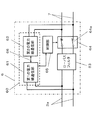
- FIG. 2 is a block diagram showing the configuration of the vehicle charging device 6 of the vehicle charging system 1 according to the embodiment of the present invention.
- the vehicle charging device 6 is installed between the in-home power line 3a and the vehicle power line 7, and is connected in parallel with the low-pass filter 63 for attenuating a high-frequency signal for power line communication, and the low-pass filter 63, and the charging instruction device.
- 5 (FIG. 1) is converted to a signal having a frequency lower than the high-frequency signal of power line communication superimposed on the in-home power line 3a, and the vehicle 8 (FIG. 1) is connected via the vehicle power line 7 by the converted low-frequency signal.
- a power line communication unit 60 that communicates, and a control unit 65 that controls connection or disconnection of the connection unit 64 based on an instruction signal of the charging instruction device 5 demodulated by the power line communication unit 60.
- the power line communication unit 60 is provided in a bypass path that bypasses the low-pass filter 63 and the connection unit 64.
- the vehicle charging device 6 attenuates the high-frequency signal of the power line communication output from the charging instruction device 5 and superimposed on the home power line 3a by the low-pass filter 63, and then outputs the signal to the vehicle power line 7, so that the power line communication
- the high-frequency signal can be made difficult to leak out of the house 2.
- the power line communication unit 60 converts the signal into a signal having a frequency lower than the high frequency signal of the power line communication used in the house 2 and communicates with the vehicle 8 outside the house 2, the signal of the power line communication used in the house 2 Can be prevented from leaking outside the house 2.
- the charging instruction device 5 can control the charging operation of the vehicle charging device 6 and can perform authentication by communicating with the vehicle 8 via the vehicle charging device 6. Thereby, the vehicle charging device 6 can supply electric power to the vehicle 8 through the vehicle power line 7 based on the instruction of the charging instruction device 5. Specifically, the charging instruction device 5 instructs the control unit 65 of the vehicle charging device 6 to permit charging only to the authenticated vehicle 8, and to the unauthorized vehicle 8 that is not authenticated. Sends instructions to refuse charging.
- the power line communication unit 60 includes a first power line communication unit 61 and a second power line communication unit 62, and the first power line communication unit 61 and the second power line communication unit 62 are connected via a dedicated data line 66.
- the first power line communication unit 61 demodulates the high frequency signal of power line communication superimposed on the in-home power line 3 a from the charging instruction device 5 and outputs the demodulated data line 66 to the dedicated data line 66.
- connection unit 64 is configured by a switch 64a, and connects or disconnects the home power line 3a and the vehicle power line 7 in a closed state or an open state.
- the control unit 65 receives the instruction signal of the charging instruction device 5 demodulated by the first power line communication unit 61.
- the control unit 65 controls the switch 64a of the connection unit 64 to the closed state (ON state) when the received instruction signal indicates that charging is permitted, and switches the switch 64a of the connection unit 64 when the instruction signal indicates that charging is not permitted. Is controlled to an open state (OFF state).
- the vehicle charging system 1 can prevent power from being supplied to the unauthorized vehicle 8, thereby preventing theft of power.
- the first power line communication unit 61 demodulates the instruction signal from the charging instruction device 5 and outputs the demodulated signal to the dedicated data line 66.
- the second power line communication unit 62 is connected to the dedicated data line 66.
- the data is modulated with a signal having a frequency (for example, a frequency of 10 KHz to 450 KHz) lower than a high frequency signal (a signal having a frequency of 2 MHz to 30 MHz) for power line communication, and is output to the vehicle power line 7.
- a signal having a frequency for example, a frequency of 10 KHz to 450 KHz
- a high frequency signal a signal having a frequency of 2 MHz to 30 MHz
- the power line noise in the frequency band of 2 to 30 MHz which is the frequency band of the high frequency signal, is smaller than the noise of the power line in the frequency band of the low frequency signal, 10 KHz to 450 KHz. It becomes faster than the signal transmission speed.
- control unit 65 performs control based on the instruction signal of the charging instruction device 5 demodulated by the first power line communication unit 61.
- the instruction signal of the charging instruction device 5 can be output from the second power line communication unit 62.
- the frequency of the instruction signal is reduced, so that radiation can be easily suppressed, and signal leakage to the vehicle power line 7 and the like can be suppressed via the control circuit.
- the charging instruction device 5 is a personal computer or the like that is used for general purposes, it is conceivable to communicate with a power line communication device other than the vehicle charging device 6.
- a power line communication device other than the vehicle charging device 6.
- the vehicle charging device 6 when the charging instruction device 5 or the power line communication device transmits a broadcast signal or multicast signal to the home power line 3a, the vehicle charging device 6 also receives the broadcast signal or multicast signal.
- the broadcast signal or the multicast signal is not a signal addressed to the vehicle charging device 6, if the signal is passed from the first power line communication unit 61 to the second power line communication unit 62, the second power line communication is performed.
- the first power line communication unit 61 analyzes the destination of the received broadcast signal or multicast signal, and does not transmit the signal to the second power line communication unit 62 when the destination is not the vehicle charging device 6.
- the first signal processing unit 14 (to be described later) analyzes the destination of the received broadcast signal or multicast signal. If the destination of the received signal is not the vehicle charging device 6, the first signal processing unit 14 does not pass the signal to the first dedicated communication unit 15 (that is, does not pass the signal to the second power line communication unit 62). ). Therefore, the broadcast signal and the multicast signal are not converted into a low-frequency signal for power line communication.
- the first signal processing unit 14 sends the signal to the second signal. Since it is not passed to the power line communication unit 62, the broadcast signal or the multicast signal is not converted into a low frequency signal for power line communication.
- connection unit 64 Even when the connection unit 64 is in the open state, the power line communication unit 60 is connected in parallel with the low-pass filter 63, so that the charging instruction device 5 can communicate with the vehicle 8 via the vehicle charging device 6. Authentication can be performed.
- the low-pass filter 63 is provided between the in-house power line 3a and the connection part 64, it may be provided between the connection part 64 and the vehicle power line 7. Also with this configuration, it is possible to suppress leakage of a high-frequency signal of power line communication used in the house 2 to a space outside the house 2 through the vehicle power line 7.
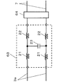
- FIG. 3 is a block diagram showing the configuration of the first power line communication unit 61 of the vehicle charging device 6 according to the embodiment of the present invention
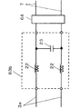
- FIG. 4 shows the second power line of the vehicle charging device 6 according to the embodiment of the present invention
- 3 is a block diagram illustrating a configuration of a communication unit 62.
- the first power line communication unit 61 is connected to the first coupler 12 and the first coupler 12 respectively connected to the pair of in-home power lines 3a via the capacitor 11, and the signal A first modulation / demodulation unit 13 that modulates or demodulates the signal, a first signal processing unit 14 that decodes a signal demodulated by the first modulation / demodulation unit 13, a first signal processing unit 14, and a dedicated data line 66.
- the first dedicated communication unit 15 is connected and transmits / receives communication information decoded by the first signal processing unit 14 via the dedicated data line 66.
- the first signal processing unit 14 is connected to the control unit 65.
- the second power line communication unit 62 is connected to the second coupler 17 connected to the pair of vehicle power lines 7 via the capacitors 16 and the second coupler 17.
- a second modulation / demodulation unit 18 for modulating or demodulating the signal
- a second signal processing unit 19 for decoding the signal demodulated by the second modulation / demodulation unit 18, a second signal processing unit 19, and a dedicated data line.
- a second dedicated communication unit 20 that transmits and receives communication information decoded by the second signal processing unit 19 via the dedicated data line 66.
- the first dedicated communication unit 15 communicates with the second dedicated communication unit 20 via a dedicated data line 66 such as Ethernet (registered trademark) or an optical fiber.
- a dedicated data line 66 such as Ethernet (registered trademark) or an optical fiber.
- the first modulation / demodulation unit 13 and the second modulation / demodulation unit 18 demodulate the communication signal superimposed on the power line (the residential power line 3a or the vehicle power line 7) and convert it into data. Also, the data is modulated into a signal superimposed on the power line.
- the first signal processing unit 14 decomposes necessary data addressed to itself from the data and sends it to the control unit 65. Further, the data sent from the charging instruction device 5 or the power storage device 10 is sent to the first modem unit 13 or the second modem unit 18 with destination information and error correction code attached.
- a transformer is used as the first coupler 12 and the second coupler 17.
- the first dedicated communication unit 15 outputs data (communication information) from the first signal processing unit 14 to the dedicated data line 66.
- the second dedicated communication unit 20 outputs data (communication information) from the second signal processing unit 19 to the dedicated data line 66.
- the Ethernet registered trademark
- the first dedicated communication unit 15 and the second dedicated communication unit 20 convert the data into an Ethernet (registered trademark) signal and output it.
- the first power line communication unit 61 and the second power line communication unit 62 perform communication operations at dedicated frequencies that are independent of each other.
- the first modem unit 13 and the second modem unit 18 perform power line communication at different frequencies.
- the second modulation / demodulation unit 18 has a frequency lower than a frequency (for example, a frequency of 2 MHz to 30 MHz) used by the first modulation / demodulation unit 13 to communicate with a device in the house 2 as a frequency when performing power line communication. (For example, a frequency of 10 KHz to 450 KHz) is used.
- a frequency of 10 KHz to 450 KHz is used.
- the high-frequency signal of the power line communication superimposed on the home power line 3a from the charging instruction device 5 is used to communicate with the devices in the house 2 by the first power line communication unit 61 and the second power line communication unit 62. It is converted into a signal having a frequency lower than the frequency to be transmitted (for example, a frequency of 2 MHz to 30 MHz), and communicates with the vehicle 8 outside the house 2 via the vehicle power line 7.
- a low-frequency signal transmitted from the vehicle 8 is a frequency used for communicating with a device in the house 2 via the second power line communication unit 62 and the first power line communication unit 61 to the home power line 3a. It is superimposed as a high-frequency signal (for example, a frequency of 2 MHz to 30 MHz) and transmitted to the charging instruction device 5.
- FIG. 5 is a block diagram showing the configuration of the low-pass filter 63 of the vehicle charging device 6 in the vehicle charging system 1 according to the embodiment of the present invention
- FIG. 6 is a block diagram showing another configuration example of the low-pass filter 63
- FIG. 6 is a block diagram showing still another configuration example of the low-pass filter 63.
- the low-pass filter 63 is composed of a balanced circuit of a T-type filter including an inductor 21, an inductor 22, and a capacitor 23.
- the low-pass filter 63 attenuates the high-frequency signal of the power line communication output from the charging instruction device 5 and superimposed on the home power line 3a and then outputs the signal to the vehicle power line 7 via the connection unit 64.
- High frequency signals can be made difficult to leak into the space outside the house 2.
- the low-pass filter 63 is configured as a T-type filter, the high-frequency signal of the power line communication output from the vehicle 8 and superimposed on the vehicle power line 7 is also attenuated and output to the residential power line 3a. Interference with low-speed power line carrier communication that has been introduced as a home automation communication means can be reduced, and intrusion of high-frequency noise (for example, vehicle charging device noise) mixed from outside the house 2 can be suppressed.
- the low-pass filter 63 is not limited to the T-type filter. Various modifications are possible according to the input / output impedance. For example, it is good also as a structure shown in FIG. 6, FIG. In other words, a ⁇ -type filter balanced circuit may be used as in the low-pass filter 63a shown in FIG. Further, an L-type filter balanced circuit may be used as in the low-pass filter 63b shown in FIG.
- FIG. 8 is a flowchart illustrating the operation of the vehicle charging system 1 according to the embodiment of the present invention.
- the connection of the vehicle 8 is detected by attaching the vehicle power line 7 of the vehicle charging device 6 to the power supply port 9 of the vehicle 8 (S100, S102).
- the charging instruction device 5 and the vehicle 8 perform an authentication operation.
- the vehicle charging system 1 transmits control information from the charging instruction device 5 to the vehicle charging device 6 based on the authentication result (S104).
- the vehicle charging device 6 receives authentication information transmitted / received between the charging instruction device 5 and the vehicle 8 (the MAC address of the power line communication unit 4 included in the charging instruction device 5 and the power line communication device included in the vehicle 8 (not shown) Relay process of the MAC address, etc.), and after the authentication process is completed, the control information transmitted from the charging instruction device 5 is received.
- the vehicle charging system 1 controls the switch 64a of the connecting portion 64 to be closed by the vehicle charging device 6 when the control information indicates that charging is permitted (S106, S108). Until charging of the vehicle 8 is completed, (S104) to (S108) are repeatedly executed.
- the vehicle charging system 1 controls the switch 64a of the connection unit 64 to be in an open state (S106, S110). Thereby, the electric power supply from the vehicle charging device 6 is stopped.
- the vehicle charging device 6 is installed between the in-home power line 3a and the vehicular power line 7, and receives a high-frequency signal for power line communication.
- a low-pass filter 63 to be attenuated, and connected to the low-pass filter 63 in parallel and converted from the charging instruction device 5 to a signal having a lower frequency than the high-frequency signal of the power line communication superimposed on the in-home power line 3a.
- a power line communication unit 60 that communicates with the vehicle 8 via the vehicle power line 7 by a signal, and a control unit that controls connection or disconnection of the connection unit 64 based on the instruction signal of the charging instruction device 5 demodulated by the power line communication unit 60 65.
- the vehicle charging device 6 is output from the charging instruction device 5 and is connected to the home power line. Since the high-frequency signal of power line communication superimposed on 3a is attenuated by the low-pass filter 63 and then output to the vehicle power line 7, the high-frequency signal of power line communication can be made difficult to leak into the space outside the house 2. Further, the power line communication unit 60 converts the signal into a signal having a frequency lower than the high frequency signal of the power line communication used in the house 2 and communicates with the vehicle 8 outside the house 2, so that the signal of the power line communication leaks outside the house 2. Can be difficult.
- the vehicle charging system 1 includes the above-described vehicle charging device 6 and the charging instruction device 5 that communicates with the vehicle charging device 6 via the in-home power line 3a.
- the vehicle charging device 6 includes the charging instruction device 5.
- the power from the in-home power line 3a is supplied to the vehicle 8 based on the instruction of the power line. Therefore, even if the charging instruction device 5 in the house 2 performs power line communication with the vehicle 8 via the vehicle charging device 6, the power line Communication signals can be made difficult to leak into the space outside the house 2.
- the purpose is to reduce the radiation of the power line communication signal from the vehicle power line without impairing the communication quality between the vehicle charging device and the charging instruction device.
- the frequency to be demodulated remains the frequency used for communication with the equipment in the house 2 (for example, the frequency of 2 MHz to 30 MHz), and the transmission signal and the transmission signal of the modulation unit mounted on the vehicle charging device.
- the level is set to a small transmission signal level of 10 to 20 dB (for example, at a frequency of 2 MHz to 30 MHz) which is a wall attenuation amount of a general house, and a normal transmission level is set in the first power line communication unit. The same effect can be obtained.
- an electric vehicle has been described as an example, the present invention is not limited to this, and can be applied to, for example, a hybrid vehicle using a motor and an engine in combination.
- the vehicle charging device 6 which performed the frequency conversion of the power line communication performed between the household power line communication apparatus (charging instruction
- the vehicle charging device 6 can also be applied to a case where a power line that transmits a high-frequency signal for power line communication (such as the home power line 3a in the above embodiment) is installed in the ground.
- a high-frequency signal for power line communication is converted into a low-frequency signal for power line communication
- a low-frequency signal for power line communication a low-frequency signal for wireless communication or a dedicated communication line is used. It may be converted into a low-frequency signal corresponding to.
- a communication circuit capable of performing wireless communication may be used instead of the second power line communication unit.
- a communication circuit corresponding to the dedicated communication line may be used.
- the high frequency signal of the power line communication output from the charging instruction device and superimposed on the home power line is attenuated by the low-pass filter and then output to the vehicle power line, so that the high frequency signal of the power line communication is not easily leaked outside the house. Can do.
- the power line communication unit converts the signal into a signal having a frequency lower than the high frequency signal of the power line communication used in the house and communicates with the vehicle outside the house, the power line communication signal can be made difficult to leak outside the house. .
- a charging device for a vehicle that stores electric power in a power storage device and supplies charging power to a vehicle such as an electric vehicle or a hybrid vehicle that travels by rotating wheels using the stored electric power, and a vehicle using the same Useful for charging systems.
Abstract
住宅内の充電指示装置が車両用充電装置を介して車両と電力線通信を行う場合であっても、電力線通信の高周波信号を住宅外に漏れにくくすることができる電力供給装置。電力供給装置としての車両用充電装置(6)は、宅内電力線(3a)と車両用電力線(7)との間に設置され、電力線通信の高周波信号を減衰させるローパスフィルタ(63)と、ローパスフィルタ(63)と並列に接続されると共に充電指示装置から宅内電力線(3a)に重畳された電力線通信の高周波信号よりも低い周波数の信号に変換し、変換された低い周波数の信号により車両用電力線(7)を介して車両と通信する電力線通信部(60)と、電力線通信部(60)により復調された充電指示装置の指示信号に基づいて接続部(64)の接続または切り離しを制御する制御部(65)と、を備えている。
Description
本発明は、蓄電装置と車輪を回転させるモータとを搭載し、蓄電装置の電力を用いてモータを駆動する車両に電力を供給する電力供給装置およびこれを用いた車両充電システムに関する。
近年、環境にやさしい車両として、蓄電装置と車輪を回転させるモータとを搭載し、蓄電装置の電力を用いてモータを駆動する電気自動車が注目されつつある。このような車両では、車両本体外の車両用充電装置から電力線を介して電力が供給され、供給された電力を蓄電装置に蓄電していた(例えば、特許文献1参照)。
ところで、一般の住宅では、車両用充電装置は住宅内の電源の電力線に接続され、住宅内の電源の電力を用いて車両に充電用の電力を供給していた。
しかしながら、住宅内の充電指示装置が電力線に高周波の信号を重畳させ車両用充電装置を介して車両と電力線通信を行う場合、充電指示装置から出力される電力線通信の高周波信号が電力線を介して住宅外に漏れやすくなるという課題があった。
そこで本発明は、住宅内の充電指示装置が車両用充電装置を介して車両と電力線通信を行う場合であっても、電力線通信の高周波信号を住宅外に漏れにくくすることを目的とする。
本発明の第1の態様に係る電力供給装置は、電力線を介して、第1の電力線通信装置と通信を行う第2の電力線通信装置を有する機器へ電力の供給を行う電力供給装置であって、前記電力線を介して、前記第1の電力線通信装置から送信されると共に第1の周波数を有する第1の信号を受信する受信部と、前記第1の信号を前記第1の周波数よりも低い第2の周波数を有する第2の信号へ変換する周波数変換部と、前記電力線を介して、前記第2の信号を前記第2の電力線通信装置へ送信する送信部と、を有する構成を採る。
この構成によれば、第1の周波数を有する第1の信号を、当該第1の周波数よりも低い周波数を有する第2の信号へ変換して機器へ送信することによって、第1の電力線通信装置と機器との間の電力線通信において、信号の漏洩を低減することができる。
本発明の第2の態様に係る電力供給装置は、前記第1の信号は、当該電力供給装置が行う電力供給に関する制御情報を有する構成を採る。
この構成によれば、第1の信号として、電力供給に関する制御情報を送信することにより、当該電力供給装置が行う電力供給を制御することが可能になる。
本発明の第3の態様に係る電力供給装置は、前記第1の信号は、前記機器を認証するための認証に関する情報を有する構成を採る。
この構成によれば、第1の信号として、前記機器を認証するための認証に関する情報を送信することにより、前記機器を認証することが可能になる。
本発明の第4の態様に係る電力供給装置は、前記電力線を断線状態または接続状態にする接続部と、前記第1の信号および前記第2の信号の少なくとも一方に基づいて、前記接続部を制御する制御部と、をさらに有する構成を採る。
この構成によれば、第1の信号および第2の信号の少なくとも一方に基づいて、電力線を断線状態または接続状態に制御することによって、機器への電力供給を制御することが可能になる。
本発明の第5の態様に係る電力供給装置は、前記電力を通過させると共に前記第1の信号を遮断する遮断部と、前記遮断部および前記接続部をバイパスするバイパス部と、をさらに有し、前記受信部、前記周波数変換部、前記送信部のうち少なくとも一つを、前記バイパス部に設けた構成を採る。
この構成によれば、電力線が断線状態の場合でも第1の信号および第2の信号を伝送することができる。即ち、機器への電力の供給と第1の信号および第2の信号の伝送を独立に行うことが可能になる。
本発明の第6の態様に係る電力供給装置は、前記遮断部は、ローパスフィルタである構成を採る。
本発明の第7の態様に係る電力供給装置は、前記ローパスフィルタは、インダクターとコンデンサとから構成されたT型フィルタ、π型フィルタまたはL型フィルタである構成を採る。
本発明の第8の態様に係る電力供給装置は、前記第1の電力線通信装置は、前記機器との認証が成功した場合は、前記第1の信号に前記機器への充電を許可する充電許可情報を格納し、前記制御部は、前記充電許可情報に基づいて、前記電力線が接続状態となるように前記接続部を制御する構成を採る。
この構成によれば、第1の信号に格納された充電許可情報に基づいて、電力線が接続状態になるように接続部を制御するので、機器の認証が成功した場合にのみ前記機器への充電を行うことができ、盗電等を防止することが可能になる。
本発明の第9の態様に係る電力供給装置は、前記第1の電力線通信装置は、前記機器との認証が失敗した場合は、前記第1の信号に前記機器への充電を許可しない充電不許可情報を格納し、前記制御部は、前記充電不許可情報に基づいて、前記電力線が断線状態となるように前記接続部を制御する構成を採る。
この構成によれば、第1の信号に格納された充電不許可情報に基づいて、電力線が断線状態になるように接続部を制御するので、機器の認証が失敗した場合は前記機器への充電を行わないので、盗電等を防止することが可能になる。
本発明の第10の態様に係る電力供給装置は、前記第1の信号は、第1の周波数帯域を用いた第1のマルチキャリア信号であり、前記第2の信号は、前記第1の周波数帯域よりも狭い第2の周波数帯域を用いた第2のマルチキャリア信号であり、前記周波数変換部は、前記受信部が受信した第1のマルチキャリア信号の宛先が当該電力供給装置とは異なる場合、前記第1のマルチキャリア信号について前記第2のマルチキャリア信号への変換を行わない構成を採る。
第1のマルチキャリア信号の宛先が当該電力供給装置と異なる場合、前記第1のマルチキャリア信号を第2のマルチキャリア信号に変換すると、第1の周波数帯域に比べて相対的に狭い第2の周波数帯域を無駄に使用することになる。そこで、この構成によれば、周波数変換部は、このような場合は第2のマルチキャリア信号への変換を行わないので、第2の周波数帯域を有効に活用することが可能になる。
本発明の第11の態様に係る電力供給装置は、前記第1の信号は、第1の周波数帯域を用いた第1のマルチキャリア信号であり、前記第2の信号は、前記第1の周波数帯域よりも狭い第2の周波数帯域を用いた第2のマルチキャリア信号であり、前記周波数変換部は、前記受信部が受信した第1のマルチキャリア信号の宛先が前記第2の電力線通信装置とは異なる場合、前記第1のマルチキャリア信号について前記第2のマルチキャリア信号への変換を行わない構成を採る。
第1のマルチキャリア信号の宛先が前記第2の電力線通信装置とは異なる場合、前記第1のマルチキャリア信号を第2のマルチキャリア信号に変換すると、第1の周波数帯域に比べて相対的に狭い第2の周波数帯域を無駄に使用することになる。そこで、この構成によれば、周波数変換部は、このような場合は第2のマルチキャリア信号への変換を行わないので、第2の周波数帯域を有効に活用することが可能になる。
本発明の第12の態様に係る車両充電システムは、上記いずれかの電力供給装置と、前記第1の電力線通信装置と、前記第2の電力線通信装置を有する車両と、を有する構成を採る。
この構成によれば、認証時や充電中に行われる第1の電力線通信装置と車両との電力線信号において、電力線通信信号の漏洩を低減することができる。
本発明によれば、充電指示装置から出力され宅内電力線に重畳された電力線通信の高周波信号をローパスフィルタにより減衰させてから車両用電力線に出力するので、電力線通信の高周波信号を住宅外に漏れにくくすることができる。また、電力線通信部は住宅内で使用される電力線通信の高周波信号よりも低い周波数の信号に変換して住宅外の車両と通信するので、電力線通信の信号を住宅外に漏れにくくすることができる。
また、本発明によれば、充電指示装置の指示に基づいて宅内電力線からの電力が車両に供給されるので、住宅内の充電指示装置が車両用充電装置を介して車両と電力線通信を行う場合であっても、電力線通信の信号を漏れにくくすることができる。
以下、本発明の一実施の形態について、図面を参照しながら説明する。なお、各図において同一または相当の部分には同一の符号を付して説明する。
(実施の形態)
まず、図1~図8を参照しながら、本発明の実施の形態における車両充電システムについて説明する。ここでは、車両として、蓄電装置と車輪を回転させるモータとを搭載し、蓄電装置に蓄電した電力を用いてモータを駆動する電気自動車の場合を例として説明する。電気自動車では、蓄電装置に蓄電された電力をモータに供給し、モータにより車輪を回転させ、他の場所に移動することができる。
まず、図1~図8を参照しながら、本発明の実施の形態における車両充電システムについて説明する。ここでは、車両として、蓄電装置と車輪を回転させるモータとを搭載し、蓄電装置に蓄電した電力を用いてモータを駆動する電気自動車の場合を例として説明する。電気自動車では、蓄電装置に蓄電された電力をモータに供給し、モータにより車輪を回転させ、他の場所に移動することができる。
図1は本発明の実施の形態における車両充電システム1の構成図である。図1において、車両充電システム1は、電力線通信部4を内蔵している充電指示装置5と、車両用充電装置6と、車両用充電装置6と車両用電力線7を介して接続された車両8とを備えている。
一般の住宅2では、充電指示装置5および車両用充電装置6は、住宅2の電源3に接続される。これにより、車両用充電装置6に必要となる電力が住宅2の電源3から供給される。車両用充電装置6は、住宅2の電源3の電力を用いて車両8に電力を供給する。
車両充電システム1では、車両用電力線7を車両8の給電口9に装着後、充電指示装置5により車両8の認証を行い、認証できた場合にのみ、車両8に電力を供給する。車両8は、車両本体8aに搭載されている蓄電装置10に給電口9を介して供給された電力を充電する。
充電指示装置5は、専用機で構成される。なお、専用機に代えてパーソナルコンピュータを用いてもよい。充電指示装置5は内蔵の電力線通信部4を介して電源3の電力線を用い車両用充電装置6と電力線通信を行う。
ところで、車両用充電装置6は住宅2内の電源3の宅内電力線3aに接続され、住宅2内の電源3の電力を用いて車両8に充電用の電力を供給する。
しかしながら、住宅2内の充電指示装置5が宅内電力線3aに高周波の信号を重畳させ車両用充電装置6を介して車両8と電力線通信を行うので、住宅2内の宅内電力線3aを介して行われる電力線通信の高周波信号が住宅2外に漏れやすくなる。電力線通信で使用される信号の周波数として、例えば、2MHz~30MHzの周波数が使用され、この高周波信号により高速通信が行える。
そこで本実施の形態では、住宅2内の充電指示装置5が車両用充電装置6を介して車両8と電力線通信を行う場合であっても、図2に示す車両用充電装置6の構成により、電力線通信の高周波信号を住宅2外に漏れにくくした。
なお、車両用充電装置6が充電を行う対象はハイブリッド自動車や電気自動車に限られない。例えば、バッテリー内蔵のバイクや自転車であっても構わないし、その他充電を必要とする電気機器や電池そのものであっても構わない。
また、充電指示装置5が送信する電力線通信の高周波信号は、車両8との認証を行うために用いられる認証情報や車両用充電装置6が行う車両への充電を制御するための制御情報である。
認証情報は、具体的には、電力線通信部4が有するアドレス情報(MACアドレス等)である。
また、制御情報は、具体的には、後述の制御部65へ送信する充電指示信号や車両8の充電状況を確認するための確認信号である。
図2は本発明の実施の形態における車両充電システム1の車両用充電装置6の構成を示すブロック図である。
すなわち、車両用充電装置6は、宅内電力線3aと車両用電力線7との間に設置され、電力線通信の高周波信号を減衰させるローパスフィルタ63と、ローパスフィルタ63と並列に接続されると共に充電指示装置5(図1)から宅内電力線3aに重畳された電力線通信の高周波信号よりも低い周波数の信号に変換し、変換された低い周波数の信号により車両用電力線7を介して車両8(図1)と通信する電力線通信部60と、電力線通信部60により復調された充電指示装置5の指示信号に基づいて接続部64の接続または切り離しを制御する制御部65と、を備えている。
電力線通信部60は、ローパスフィルタ63および接続部64をバイパスするバイパス経路に設けられる。
この構成により、車両用充電装置6は、充電指示装置5から出力され宅内電力線3aに重畳された電力線通信の高周波信号をローパスフィルタ63により減衰させてから車両用電力線7に出力するので、電力線通信の高周波信号を住宅2外に漏れにくくすることができる。また、電力線通信部60は住宅2内で使用される電力線通信の高周波信号よりも低い周波数の信号に変換し住宅2外の車両8と通信するので、住宅2内で使用される電力線通信の信号を住宅2外に漏れにくくすることができる。
充電指示装置5は、車両用充電装置6の充電動作を制御すると共に、車両用充電装置6を介して車両8との通信により認証を行うことができる。これにより、車両用充電装置6は充電指示装置5の指示に基づいて、電力を車両用電力線7を介して車両8に供給することができる。具体的には、充電指示装置5は、車両用充電装置6の制御部65に対して、認証できた車両8に対してのみ充電許可の指示を行い、認証されない不正規な車両8に対しては充電不許可の指示を送る。
電力線通信部60は、第1の電力線通信部61と第2の電力線通信部62とを有し、第1の電力線通信部61と第2の電力線通信部62は専用データ線66を介して接続されている。また、第1の電力線通信部61は、充電指示装置5から宅内電力線3aに重畳された電力線通信の高周波信号を復調し、専用データ線66に出力する。
接続部64は、スイッチ64aで構成され、閉状態または開状態により宅内電力線3aと車両用電力線7とを接続または切り離しを行う。
制御部65は第1の電力線通信部61により復調された充電指示装置5の指示信号を受信する。そして、制御部65は受信した指示信号が充電許可の場合には接続部64のスイッチ64aを閉状態(ON状態)に制御し、指示信号が充電不許可の場合には接続部64のスイッチ64aを開状態(OFF状態)に制御する。これにより、車両充電システム1では不正規な車両8に対して電力を供給しないようにできるので、盗電を防止することができる。
また、第1の電力線通信部61は、充電指示装置5からの指示信号を復調して専用データ線66に出力し、後述するように、第2の電力線通信部62は、専用データ線66のデータを電力線通信の高周波信号(2MHz~30MHzの周波数の信号)よりも低い周波数(例えば、10KHz~450KHzの周波数)の信号で変調して車両用電力線7に出力する。これにより、低い周波数の信号は輻射を抑えやすいので、住宅2内で使用される電力線通信の高周波信号が車両用電力線7を介して住宅2外の空間へ漏れるのを抑えることができる。
なお、一般的に高周波信号の周波数帯域である2~30MHzにおける電力線のノイズは、低周波信号の周波数帯域である10KHz~450KHzにおける電力線のノイズよりも小さいので、高周波信号の伝送速度は、低周波信号の伝送速度よりも速くなる。
また、制御部65は第1の電力線通信部61により復調された充電指示装置5の指示信号に基づいて制御を行う。
なお、充電指示装置5の指示信号については、第2の電力線通信部62から出力することも可能である。第2の電力線通信部62から指示信号を出力する場合は、指示信号の周波数が低下するので輻射を抑えやすくなり、制御回路を介して車両用電力線7などへの信号漏れを抑えることができる。
また、充電指示装置5が汎用的に用いられるパーソナルコンピュータ等の場合は、車両用充電装置6以外の電力線通信装置とも通信を行うことが考えられる。この場合、充電指示装置5や当該電力線通信装置は、宅内電力線3aにブロードキャスト信号やマルチキャスト信号を送信した場合は、車両用充電装置6も当該ブロードキャスト信号や当該マルチキャスト信号を受信する。しかしながら、当該ブロードキャスト信号や当該マルチキャスト信号が車両用充電装置6宛の信号でない場合、当該信号を第1の電力線通信部61から第2の電力線通信部62へ渡してしまうと、第2の電力線通信部62が通信に使用する帯域は第1の電力線通信部61が使用する帯域に比べて少ないので、第2の電力線通信部62の通信が滞ってしまうという問題が生じる。そこで、第1の電力線通信部61は、受信したブロードキャスト信号やマルチキャスト信号の宛先を解析し、その宛先が車両用充電装置6でない場合は、当該信号を第2の電力線通信部62へ伝送しない。受信したブロードキャスト信号やマルチキャスト信号が有する宛先の解析は、後述する第1の信号処理部14が行う。第1の信号処理部14は、受信した信号の宛先が車両用充電装置6でない場合は、当該信号を第1の専用通信部15へ渡さない(即ち、第2の電力線通信部62へ渡さない)。したがって、当該ブロードキャスト信号や当該マルチキャスト信号は、電力線通信の低周波信号へ変換されることがない。
また同様に、充電指示装置5や当該電力線通信装置が送信したブロードキャスト信号やマルチキャスト信号の宛先が第2の電力線通信部62でない場合も、第1の信号処理部14は、当該信号を第2の電力線通信部62へ渡さないので、当該ブロードキャスト信号や当該マルチキャスト信号は、電力線通信の低周波信号へ変換されることがない。
なお、接続部64が開状態の場合でも電力線通信部60がローパスフィルタ63と並列に接続されているので、充電指示装置5は車両用充電装置6を介して車両8と通信でき、車両8の認証を行うことができる。
また、ローパスフィルタ63を宅内電力線3aと接続部64との間に設けたが、接続部64と車両用電力線7との間に設けてもよい。この構成によっても、住宅2内で使用される電力線通信の高周波信号が車両用電力線7を介して住宅2外の空間へ漏れるのを抑えることができる。
次に、図3および図4を参照しながら、車両用充電装置6における電力線通信部60の第1の電力線通信部61、第2の電力線通信部62の具体的な構成について説明する。図3は本発明の実施の形態における車両用充電装置6の第1の電力線通信部61の構成を示すブロック図、図4は本発明の実施の形態における車両用充電装置6の第2の電力線通信部62の構成を示すブロック図である。
図3に示すように、第1の電力線通信部61は、一対の宅内電力線3aにそれぞれコンデンサ11を介して接続された第1の結合器12と、第1の結合器12と接続され、信号を変調または復調する第1の変復調部13と、第1の変復調部13により復調された信号を解読する第1の信号処理部14と、第1の信号処理部14と専用データ線66とに接続され、第1の信号処理部14で解読される通信情報を専用データ線66を介して送受信する第1の専用通信部15とを有している。また、第1の信号処理部14は制御部65と接続されている。
また、図4に示すように、第2の電力線通信部62は、一対の車両用電力線7にそれぞれコンデンサ16を介して接続された第2の結合器17と、第2の結合器17と接続され、信号を変調または復調する第2の変復調部18と、第2の変復調部18で復調された信号を解読する第2の信号処理部19と、第2の信号処理部19と専用データ線66とに接続され、第2の信号処理部19で解読される通信情報を専用データ線66を介して送受信する第2の専用通信部20とを有している。
そして、第1の専用通信部15は、第2の専用通信部20とイーサネット(登録商標)や光ファイバーなど専用データ線66を介して通信を行う。
第1の変復調部13および第2の変復調部18は、電力線(宅内電力線3aまたは車両用電力線7)に重畳された通信信号を復調してデータに直す。また、データを電力線に重畳する信号に変調する。第1の信号処理部14は、データから自己宛の必要なデータを分解して制御部65に送る。また、充電指示装置5や蓄電装置10から送られたデータをあて先情報やエラー訂正符号をつけて第1の変復調部13または第2の変復調部18に送る。
第1の結合器12および第2の結合器17としてトランスを用いる。第1の専用通信部15は、第1の信号処理部14からのデータ(通信情報)を専用データ線66に出力する。同様に、第2の専用通信部20は、第2の信号処理部19からのデータ(通信情報)を専用データ線66に出力する。第1の専用通信部15および第2の専用通信部20は、専用データ線66としてイーサネット(登録商標)が用いられる場合、データをイーサネット(登録商標)信号に変換して出力する。
また、本実施の形態では、第1の電力線通信部61と第2の電力線通信部62とはそれぞれが独立した専用の周波数で通信動作を行う。
具体的には、第1の変復調部13と第2の変復調部18はそれぞれが異なる周波数で電力線通信を行う。第2の変復調部18は、電力線通信を行う際の周波数として、第1の変復調部13が住宅2内の機器と通信するために使用する周波数(例えば、2MHz~30MHzの周波数)よりも低い周波数(例えば、10KHz~450KHzの周波数)を使用する。宅内電力線3aに重畳される電力線通信の高周波信号の周波数に比べて低い周波数の信号に変換して通信を行うことで、車両用電力線7からの電波漏れを抑えやすくなり、住宅2外の空間に電力線通信の信号を漏れにくくすることができる。
このように、充電指示装置5から宅内電力線3aに重畳された電力線通信の高周波信号は、第1の電力線通信部61および第2の電力線通信部62により住宅2内の機器と通信するために使用する周波数(例えば、2MHz~30MHzの周波数)よりも低い周波数の信号に変換され、住宅2外の車両8と車両用電力線7を介して通信する。一方、車両8から送信される周波数の低い信号は、第2の電力線通信部62および第1の電力線通信部61を介して、宅内電力線3aに住宅2内の機器と通信するために使用する周波数(例えば、2MHz~30MHzの周波数)の高周波信号として重畳され、充電指示装置5に伝達される。
これにより、住宅2内の充電指示装置5が車両用充電装置6を介して車両8と電力線通信を行う場合であっても、電力線通信の信号を住宅2外の空間に漏れにくくすることができる。
なお、上述の実施の形態では、第1の変復調部13および第2の変復調部18を共にバイパス経路上に設けた例を説明したが、第1の変復調部13および第2の変復調部18の少なくとも一方をバイパス経路上に設けても、上述の実施の形態と同じ技術的効果が得られる。すなわち、充電指示装置5から送信された電力線通信の高周波信号を車両8側へ送信することが可能である。
次に、図5~図7を参照しながら、車両用充電装置6におけるローパスフィルタ63の具体的な構成について説明する。
図5は本発明の実施の形態における車両充電システム1における車両用充電装置6のローパスフィルタ63の構成を示すブロック図、図6は同ローパスフィルタ63の他の構成例を示すブロック図、図7は同ローパスフィルタ63のさらに他の構成例を示すブロック図である。
図5に示すように、ローパスフィルタ63は、インダクター21、インダクター22とコンデンサ23によるT型フィルタの平衡回路により構成される。これにより、ローパスフィルタ63は、充電指示装置5から出力され宅内電力線3aに重畳された電力線通信の高周波信号を減衰させてから接続部64を介して車両用電力線7に出力するので、電力線通信の高周波信号を住宅2外の空間に漏れにくくすることができる。また、ローパスフィルタ63がT型フィルタで構成されたことにより、車両8から出力され車両用電力線7に重畳された電力線通信の高周波信号も減衰されてから宅内電力線3aに出力されるので、例えば、かねてよりホームオートメーション用通信手段として導入されている低速電力線搬送通信との干渉を低減できると共に、住宅2外から混入する高周波の雑音(例えば、車両充電装置雑音など)の侵入も抑えることができる。
なお、ローパスフィルタ63はT型フィルタに限定されるものではない。入出力のインピーダンスに応じて種々の変形が可能である。例えば、図6、図7に示す構成としてもよい。すなわち、図6に示すローパスフィルタ63aのように、π型フィルタの平衡回路により構成してもよい。さらに、図7に示すローパスフィルタ63bのように、L型フィルタの平衡回路により構成してもよい。
これらのいずれのフィルタ構成を用いても、宅内電力線3aに重畳される高周波信号は減衰され、住宅2外に漏れにくくなる。
次に、図1、図2および図8を参照しながら、車両充電システム1の動作について説明する。図8は、本発明の実施の形態における車両充電システム1の動作を説明するフローチャートである。
まず、車両充電システム1では、車両用充電装置6の車両用電力線7が車両8の給電口9に装着されることにより、車両8の接続を検出する(S100、S102)。
次に、車両充電システム1は、車両8の接続が検出されると、充電指示装置5と車両8とが認証動作を行う。車両充電システム1は、この認証結果に基づいて充電指示装置5から車両用充電装置6に制御情報が送信される(S104)。
S104において、車両充電装置6は充電指示装置5と車両8との間で送受信される認証に関する情報(充電指示装置5が有する電力線通信部4のMACアドレスや車両8が有する電力線通信装置(図示せず)が有するMACアドレスなど)の中継処理を行い、認証処理の完了後は、充電指示装置5から送信された制御情報の受信処理を行う。
車両充電システム1は、車両用充電装置6により、制御情報が充電許可の場合には接続部64のスイッチ64aを閉状態に制御する(S106、S108)。車両8の充電が完了するまで、(S104)~(S108)が繰り返し実行される。
一方、車両充電システム1は、制御情報が充電不許可の場合には接続部64のスイッチ64aを開状態に制御する(S106、S110)。これにより、車両用充電装置6からの電力供給が停止される。
以上のように本実施の形態によれば、図1および図2に示すように、車両用充電装置6は、宅内電力線3aと車両用電力線7との間に設置され、電力線通信の高周波信号を減衰させるローパスフィルタ63と、ローパスフィルタ63と並列に接続されると共に充電指示装置5から宅内電力線3aに重畳された電力線通信の高周波信号よりも低い周波数の信号に変換し、変換された低い周波数の信号により車両用電力線7を介して車両8と通信する電力線通信部60と、電力線通信部60により復調された充電指示装置5の指示信号に基づいて接続部64の接続または切り離しを制御する制御部65と、を備えている。
この構成により、住宅2内の充電指示装置5が車両用充電装置6を介して車両8と電力線通信を行う場合であっても、車両用充電装置6は、充電指示装置5から出力され宅内電力線3aに重畳された電力線通信の高周波信号をローパスフィルタ63により減衰させてから車両用電力線7に出力するので、電力線通信の高周波信号を住宅2外の空間に漏れにくくすることができる。また、電力線通信部60は住宅2内で使用される電力線通信の高周波信号よりも低い周波数の信号に変換し、住宅2外の車両8と通信するので、電力線通信の信号を住宅2外に漏れにくくすることができる。
また、車両充電システム1は、上記した車両用充電装置6と、車両用充電装置6と宅内電力線3aを介して通信する充電指示装置5とを備え、車両用充電装置6は、充電指示装置5の指示に基づいて宅内電力線3aからの電力を車両8に供給するので、住宅2内の充電指示装置5が車両用充電装置6を介して車両8と電力線通信を行う場合であっても、電力線通信の信号を住宅2外の空間に漏れにくくすることができる。
なお、本発明の具体的な構成は、上述した実施の形態に限られるものではなく、発明の要旨を逸脱しない範囲で種々の変更および修正が可能である。
例えば、車両用充電装置と充電指示装置の通信品質を損なわないで、かつ、車両用電力線からの電力線通信信号の輻射を小さくするのが目的であるから、第2の電力線通信部62にて変調または復調される周波数は、住宅2内の機器と通信するために使用する周波数(例えば、2MHz~30MHzの周波数)のままで、その送信信号および車両用充電装置に搭載される変調部の送信信号レベルを、一般住宅の、壁減衰量である10~20dB(例えば、2MHz~30MHzの周波数の時)以上の小さな送信信号レベルとし、第1の電力線通信部では、通常の送信レベルとすることで、同様の効果を得ることができる。
また、電気自動車を例に説明したが、本発明はこれに限定されず、例えば、モータとエンジンとを併用するハイブリッド自動車にも適用することができる。
また、上記実施の形態においては、家庭内の電力線通信装置(充電指示装置5)と屋外の車両8との間で実行される電力線通信の周波数変換を行う車両用充電装置6について説明を行ったが、車両用充電装置6は、電力線通信の高周波信号を伝送する電力線(上記実施の形態における宅内電力線3aに相等)が地中に設置されている場合にも適用可能である。
また、上記実施の形態においては、電力線通信の高周波信号を電力線通信の低周波信号に変換した例を説明したが、電力線通信の低周波信号に代わって、無線通信の低周波信号や通信専用線に対応した低周波信に変換しても良い。
電力線通信の高周波信号を無線通信の低周波信号に変換する場合は、第2の電力線通信部に代わって、無線通信を行うことの可能な通信回路等を用いれば良く、通信専用線に対応した低周波信号に変換する場合は、当該通信専用線に対応した通信回路を用いれば良く。
2010年1月13日出願の特願2010-004720の日本出願に含まれる明細書、図面および要約書の開示内容は、すべて本願に援用される。
本発明では、充電指示装置から出力され宅内電力線に重畳された電力線通信の高周波信号をローパスフィルタにより減衰させてから車両用電力線に出力するので、電力線通信の高周波信号を住宅外に漏れにくくすることができる。また、電力線通信部は住宅内で使用される電力線通信の高周波信号よりも低い周波数の信号に変換して住宅外の車両と通信するので、電力線通信の信号を住宅外に漏れにくくすることができる。
これにより、蓄電装置に電力を蓄電し、この蓄電した電力を利用して車輪を回転させて走行する電気自動車やハイブリッド自動車などの車両に充電電力を供給する車両用充電装置およびこれを用いた車両充電システムに有用なものである。
1 車両充電システム
2 住宅
3 電源
3a 宅内電力線
4,60 電力線通信部
5 充電指示装置
6 車両用充電装置
7 車両用電力線
8 車両
8a 車両本体
9 給電口
10 蓄電装置
11,16,23 コンデンサ
12 第1の結合器
13 第1の変復調部
14 第1の信号処理部
15 第1の専用通信部
17 第2の結合器
18 第2の変復調部
19 第2の信号処理部
20 第2の専用通信部
21,22 インダクター
61 第1の電力線通信部
62 第2の電力線通信部
63,63a,63b ローパスフィルタ
64 接続部
64a スイッチ
65 制御部
66 専用データ線
2 住宅
3 電源
3a 宅内電力線
4,60 電力線通信部
5 充電指示装置
6 車両用充電装置
7 車両用電力線
8 車両
8a 車両本体
9 給電口
10 蓄電装置
11,16,23 コンデンサ
12 第1の結合器
13 第1の変復調部
14 第1の信号処理部
15 第1の専用通信部
17 第2の結合器
18 第2の変復調部
19 第2の信号処理部
20 第2の専用通信部
21,22 インダクター
61 第1の電力線通信部
62 第2の電力線通信部
63,63a,63b ローパスフィルタ
64 接続部
64a スイッチ
65 制御部
66 専用データ線
Claims (12)
- 電力線を介して、第1の電力線通信装置と通信を行う第2の電力線通信装置を有する機器へ電力の供給を行う電力供給装置であって、
前記電力線を介して、前記第1の電力線通信装置から送信されると共に第1の周波数を有する第1の信号を受信する受信部と、
前記第1の信号を前記第1の周波数よりも低い第2の周波数を有する第2の信号へ変換する周波数変換部と、
前記電力線を介して、前記第2の信号を前記第2の電力線通信装置へ送信する送信部と、
を有する電力供給装置。 - 前記第1の信号は、当該電力供給装置が行う電力供給に関する制御情報を有する、
請求項1記載の電力供給装置。 - 前記第1の信号は、前記機器を認証するための認証に関する情報を有する、
請求項1記載の電力供給装置。 - 前記電力線を断線状態または接続状態にする接続部と、
前記第1の信号および前記第2の信号の少なくとも一方に基づいて、前記接続部を制御する制御部と、をさらに有する、
請求項1~3のいずれかに記載の電力供給装置。 - 前記電力を通過させると共に前記第1の信号を遮断する遮断部と、
前記遮断部および前記接続部をバイパスするバイパス部と、をさらに有し、
前記受信部、前記周波数変換部、前記送信部のうち少なくとも一つを、前記バイパス部に設けた、
請求項4記載の電力供給装置。 - 前記遮断部は、ローパスフィルタである、
請求項5記載の電力供給装置。 - 前記ローパスフィルタは、インダクターとコンデンサとから構成されたT型フィルタ、π型フィルタまたはL型フィルタである、
請求項6記載の電力供給装置。 - 前記第1の電力線通信装置は、前記機器との認証が成功した場合は、前記第1の信号に前記機器への充電を許可する充電許可情報を格納し、
前記制御部は、前記充電許可情報に基づいて、前記電力線が接続状態となるように前記接続部を制御する、
請求項4または5記載の電力供給装置。 - 前記第1の電力線通信装置は、前記機器との認証が失敗した場合は、前記第1の信号に前記機器への充電を許可しない充電不許可情報を格納し、
前記制御部は、前記充電不許可情報に基づいて、前記電力線が断線状態となるように前記接続部を制御する、
請求項4または5記載の電力供給装置。 - 前記第1の信号は、第1の周波数帯域を用いた第1のマルチキャリア信号であり、
前記第2の信号は、前記第1の周波数帯域よりも狭い第2の周波数帯域を用いた第2のマルチキャリア信号であり、
前記周波数変換部は、前記受信部が受信した第1のマルチキャリア信号の宛先が当該電力供給装置とは異なる場合、前記第1のマルチキャリア信号について前記第2のマルチキャリア信号への変換を行わない、
請求項1~9のいずれかに記載の電力供給装置。 - 前記第1の信号は、第1の周波数帯域を用いた第1のマルチキャリア信号であり、
前記第2の信号は、前記第1の周波数帯域よりも狭い第2の周波数帯域を用いた第2のマルチキャリア信号であり、
前記周波数変換部は、前記受信部が受信した第1のマルチキャリア信号の宛先が前記第2の電力線通信装置とは異なる場合、前記第1のマルチキャリア信号について前記第2のマルチキャリア信号への変換を行わない、
請求項1~9のいずれかに記載の電力供給装置。 - 請求項1~11のいずれかに記載の電力供給装置と、
前記第1の電力線通信装置と、
前記第2の電力線通信装置を有する車両と、
を有する車両充電システム。
Priority Applications (4)
| Application Number | Priority Date | Filing Date | Title |
|---|---|---|---|
| EP11732774.2A EP2525466B1 (en) | 2010-01-13 | 2011-01-12 | Electric power supply device and vehicle charge system |
| CN201180005886.3A CN102742115B (zh) | 2010-01-13 | 2011-01-12 | 供电装置和车辆充电系统 |
| JP2011549930A JP5654495B2 (ja) | 2010-01-13 | 2011-01-12 | 電力供給装置および車両充電システム |
| US13/546,707 US9300362B2 (en) | 2010-01-13 | 2012-07-11 | Power supply apparatus and vehicle charging apparatus |
Applications Claiming Priority (2)
| Application Number | Priority Date | Filing Date | Title |
|---|---|---|---|
| JP2010-004720 | 2010-01-13 | ||
| JP2010004720 | 2010-01-13 |
Related Child Applications (1)
| Application Number | Title | Priority Date | Filing Date |
|---|---|---|---|
| US13/546,707 Continuation-In-Part US9300362B2 (en) | 2010-01-13 | 2012-07-11 | Power supply apparatus and vehicle charging apparatus |
Publications (1)
| Publication Number | Publication Date |
|---|---|
| WO2011086899A1 true WO2011086899A1 (ja) | 2011-07-21 |
Family
ID=44304177
Family Applications (1)
| Application Number | Title | Priority Date | Filing Date |
|---|---|---|---|
| PCT/JP2011/000095 WO2011086899A1 (ja) | 2010-01-13 | 2011-01-12 | 電力供給装置および車両充電システム |
Country Status (5)
| Country | Link |
|---|---|
| US (1) | US9300362B2 (ja) |
| EP (1) | EP2525466B1 (ja) |
| JP (1) | JP5654495B2 (ja) |
| CN (1) | CN102742115B (ja) |
| WO (1) | WO2011086899A1 (ja) |
Families Citing this family (18)
| Publication number | Priority date | Publication date | Assignee | Title |
|---|---|---|---|---|
| US8841881B2 (en) | 2010-06-02 | 2014-09-23 | Bryan Marc Failing | Energy transfer with vehicles |
| US9623761B2 (en) * | 2010-12-22 | 2017-04-18 | Ford Global Technologies, Llc | Vehicle and method for authenticating a charge station |
| JP6245494B2 (ja) * | 2013-03-28 | 2017-12-13 | パナソニックIpマネジメント株式会社 | 車両用電力装置 |
| EP3001536A4 (en) * | 2013-05-23 | 2016-12-07 | Nec Corp | COMMUNICATION SYSTEM, METHOD FOR CONTROLLING AN ELECTRIC POWER SUPPLY, AND NON-TRANSIENT COMPUTER READABLE MEDIUM FOR CONTROLLING AN ELECTRICAL POWER SUPPLY |
| CN104377673A (zh) * | 2013-08-13 | 2015-02-25 | 中兴通讯股份有限公司 | 浪涌防护装置和方法 |
| KR101509752B1 (ko) * | 2013-12-23 | 2015-04-07 | 현대자동차 주식회사 | 차량용 충전 장치 및 충전 방법 |
| JP6003908B2 (ja) * | 2014-01-28 | 2016-10-05 | 株式会社デンソー | 充電装置および車載機 |
| DE102014220088A1 (de) * | 2014-10-02 | 2016-04-07 | Robert Bosch Gmbh | Leistungsschalter, Batteriesystem und Verfahren zum Betreiben eines Leistungsschalters |
| JP6098653B2 (ja) * | 2015-02-17 | 2017-03-22 | トヨタ自動車株式会社 | 給電装置及びそれを備えた車両 |
| DE102016212246A1 (de) * | 2016-07-05 | 2018-01-11 | Bayerische Motoren Werke Aktiengesellschaft | Verfahren und Systemanordnung zum Identifizieren eines Fahrzeugs an einer Ladestation |
| US11113953B2 (en) * | 2016-09-14 | 2021-09-07 | Ford Global Technologies, Llc | Vehicle-paired device range extension method and system |
| CN107627867B (zh) * | 2017-01-09 | 2020-12-08 | 上海蔚来汽车有限公司 | 待充电对象充电授权方法、充电设备自动授权方法和系统 |
| JP6812537B2 (ja) * | 2017-04-07 | 2021-01-13 | オッポ広東移動通信有限公司Guangdong Oppo Mobile Telecommunications Corp., Ltd. | 無線充電システム、装置、方法及び充電対象機器 |
| KR102001562B1 (ko) * | 2017-04-28 | 2019-07-19 | 한국전력공사 | 전기차 충전을 위한 다중통신 제어 장치 및 방법 |
| US10003382B1 (en) * | 2017-08-14 | 2018-06-19 | The Boeing Company | Communication between a vehicle and a ground terminal over a ground power line |
| US11787302B2 (en) * | 2020-08-12 | 2023-10-17 | Hyundai Motor Company | Charging control device for electric vehicle and method thereof |
| CA3216602A1 (en) * | 2021-05-04 | 2022-11-10 | Peter Mankowski | Methods and systems for operating an electric vehicle |
| US11956026B2 (en) | 2022-05-09 | 2024-04-09 | GM Global Technology Operations LLC | System and method for power line communication (PLC) and data flow control |
Citations (4)
| Publication number | Priority date | Publication date | Assignee | Title |
|---|---|---|---|---|
| US4475209A (en) * | 1982-04-23 | 1984-10-02 | Westinghouse Electric Corp. | Regenerator for an intrabundle power-line communication system |
| WO2001054297A1 (en) * | 2000-01-20 | 2001-07-26 | Current Technologies, Llc | Method of isolating data in a power line communication network |
| WO2009090813A1 (ja) * | 2008-01-15 | 2009-07-23 | Toyota Jidosha Kabushiki Kaisha | 電動車両の充電システム |
| JP2010004720A (ja) | 2008-06-23 | 2010-01-07 | Olympus Corp | 超音波モータ |
Family Cites Families (9)
| Publication number | Priority date | Publication date | Assignee | Title |
|---|---|---|---|---|
| JPS62196926A (ja) * | 1986-02-25 | 1987-08-31 | Nec Corp | マイクロ波通信回線用回線断救済方式 |
| EP1114525A2 (de) * | 1998-09-15 | 2001-07-11 | Siemens Aktiengesellschaft | Anordnung und verfahren zur bildung eines gesamtsignals, anordnung und verfahren zur bildung eines stromsignals und eines ersten kommunikationssignals, kommunikationssystem und verfahren zur übertragung eines ersten gesamtsignals und eines zweiten gesamtsignals |
| JP2004222176A (ja) * | 2003-01-17 | 2004-08-05 | Sony Corp | 通信システム及び通信方法 |
| US7209719B2 (en) * | 2003-01-28 | 2007-04-24 | Gateway Inc. | Home power line network connected phone |
| CN100508417C (zh) * | 2004-03-23 | 2009-07-01 | 中国电力科学研究院 | 多速率混合的电力线宽带接入系统及其中继器 |
| JP4353197B2 (ja) * | 2006-03-13 | 2009-10-28 | トヨタ自動車株式会社 | 車両および電気機器 |
| JP2008227885A (ja) * | 2007-03-13 | 2008-09-25 | Yamaha Corp | 電力線搬送通信の伝送線路構造および電力線開閉器 |
| JP2008244701A (ja) * | 2007-03-27 | 2008-10-09 | Smk Corp | 電力線通信システム |
| JP2009296824A (ja) * | 2008-06-06 | 2009-12-17 | Toyota Industries Corp | 充電システム |
-
2011
- 2011-01-12 CN CN201180005886.3A patent/CN102742115B/zh active Active
- 2011-01-12 JP JP2011549930A patent/JP5654495B2/ja active Active
- 2011-01-12 EP EP11732774.2A patent/EP2525466B1/en active Active
- 2011-01-12 WO PCT/JP2011/000095 patent/WO2011086899A1/ja active Application Filing
-
2012
- 2012-07-11 US US13/546,707 patent/US9300362B2/en active Active
Patent Citations (5)
| Publication number | Priority date | Publication date | Assignee | Title |
|---|---|---|---|---|
| US4475209A (en) * | 1982-04-23 | 1984-10-02 | Westinghouse Electric Corp. | Regenerator for an intrabundle power-line communication system |
| WO2001054297A1 (en) * | 2000-01-20 | 2001-07-26 | Current Technologies, Llc | Method of isolating data in a power line communication network |
| WO2009090813A1 (ja) * | 2008-01-15 | 2009-07-23 | Toyota Jidosha Kabushiki Kaisha | 電動車両の充電システム |
| JP2009171700A (ja) | 2008-01-15 | 2009-07-30 | Toyota Motor Corp | 電動車両の充電システム |
| JP2010004720A (ja) | 2008-06-23 | 2010-01-07 | Olympus Corp | 超音波モータ |
Also Published As
| Publication number | Publication date |
|---|---|
| CN102742115B (zh) | 2015-01-21 |
| JPWO2011086899A1 (ja) | 2013-05-16 |
| EP2525466A1 (en) | 2012-11-21 |
| US20120274278A1 (en) | 2012-11-01 |
| JP5654495B2 (ja) | 2015-01-14 |
| EP2525466A4 (en) | 2015-10-07 |
| US9300362B2 (en) | 2016-03-29 |
| EP2525466B1 (en) | 2020-03-11 |
| CN102742115A (zh) | 2012-10-17 |
Similar Documents
| Publication | Publication Date | Title |
|---|---|---|
| JP5654495B2 (ja) | 電力供給装置および車両充電システム | |
| JP5853156B2 (ja) | 車両充電装置およびこれを用いた車両充電システム | |
| CA2772573A1 (en) | Power line communications apparatus | |
| CN102427376A (zh) | 一种电力线载波通信系统及方法 | |
| WO2014015711A1 (zh) | 收发信机和干扰对消方法 | |
| JP2005520390A (ja) | 電力線通信システムのためのリピータ | |
| CN102195679B (zh) | 电力线载波调制方法、解调方法、电路及芯片 | |
| EP2951049A2 (en) | Switching communication devices between different communication media | |
| JP2002280240A (ja) | 回転型非接触コネクタ及び非回転型非接触コネクタ | |
| CN108880624B (zh) | 一种结合nfc、电力载波和无线通信模块的soc通信芯片 | |
| WO2003063459B1 (en) | Power line communication system combining high bitrate and low bitrate transmissions | |
| JP4470871B2 (ja) | 通信装置 | |
| CN111106880B (zh) | 飞行器的无线测试发射控制系统及方法 | |
| CN206658201U (zh) | 一种多功能混传双工收发设备 | |
| CN109565520A (zh) | 具有不同lte等级的两个调制解调器的机动车 | |
| JP2004120740A (ja) | 車両用電源重畳多重通信装置 | |
| TWI807676B (zh) | 信號處理裝置 | |
| CN105162485A (zh) | 一种跳频通信电路 | |
| KR102086599B1 (ko) | Notch 대역 제어 장치를 포함한 PLC 모뎀 | |
| JP2000232462A (ja) | ホームネットワークシステム | |
| CN113595584B (zh) | 一种自干扰信号消除装置及其消除方法 | |
| CN106506041A (zh) | 一种电力猫 | |
| CN106487420A (zh) | 基于电力线载波通信的机车重联方法 | |
| CN1409496A (zh) | 一种电力线载波通信的新方法 | |
| KR20050047762A (ko) | 신호 차단 장치 및 이를 이용한 티디디 통신 시스템 |
Legal Events
| Date | Code | Title | Description |
|---|---|---|---|
| WWE | Wipo information: entry into national phase |
Ref document number: 201180005886.3 Country of ref document: CN |
|
| WWE | Wipo information: entry into national phase |
Ref document number: 2011549930 Country of ref document: JP |
|
| WWE | Wipo information: entry into national phase |
Ref document number: 2011732774 Country of ref document: EP |
|
| NENP | Non-entry into the national phase |
Ref country code: DE |