EP2525466A1 - Electric power supply device and vehicle charge system - Google Patents
Electric power supply device and vehicle charge system Download PDFInfo
- Publication number
- EP2525466A1 EP2525466A1 EP11732774A EP11732774A EP2525466A1 EP 2525466 A1 EP2525466 A1 EP 2525466A1 EP 11732774 A EP11732774 A EP 11732774A EP 11732774 A EP11732774 A EP 11732774A EP 2525466 A1 EP2525466 A1 EP 2525466A1
- Authority
- EP
- European Patent Office
- Prior art keywords
- power line
- signal
- section
- line communication
- vehicle
- Prior art date
- Legal status (The legal status is an assumption and is not a legal conclusion. Google has not performed a legal analysis and makes no representation as to the accuracy of the status listed.)
- Granted
Links
Images


Classifications
-
- H—ELECTRICITY
- H04—ELECTRIC COMMUNICATION TECHNIQUE
- H04B—TRANSMISSION
- H04B3/00—Line transmission systems
- H04B3/54—Systems for transmission via power distribution lines
- H04B3/542—Systems for transmission via power distribution lines the information being in digital form
-
- B—PERFORMING OPERATIONS; TRANSPORTING
- B60—VEHICLES IN GENERAL
- B60L—PROPULSION OF ELECTRICALLY-PROPELLED VEHICLES; SUPPLYING ELECTRIC POWER FOR AUXILIARY EQUIPMENT OF ELECTRICALLY-PROPELLED VEHICLES; ELECTRODYNAMIC BRAKE SYSTEMS FOR VEHICLES IN GENERAL; MAGNETIC SUSPENSION OR LEVITATION FOR VEHICLES; MONITORING OPERATING VARIABLES OF ELECTRICALLY-PROPELLED VEHICLES; ELECTRIC SAFETY DEVICES FOR ELECTRICALLY-PROPELLED VEHICLES
- B60L53/00—Methods of charging batteries, specially adapted for electric vehicles; Charging stations or on-board charging equipment therefor; Exchange of energy storage elements in electric vehicles
- B60L53/60—Monitoring or controlling charging stations
-
- B—PERFORMING OPERATIONS; TRANSPORTING
- B60—VEHICLES IN GENERAL
- B60L—PROPULSION OF ELECTRICALLY-PROPELLED VEHICLES; SUPPLYING ELECTRIC POWER FOR AUXILIARY EQUIPMENT OF ELECTRICALLY-PROPELLED VEHICLES; ELECTRODYNAMIC BRAKE SYSTEMS FOR VEHICLES IN GENERAL; MAGNETIC SUSPENSION OR LEVITATION FOR VEHICLES; MONITORING OPERATING VARIABLES OF ELECTRICALLY-PROPELLED VEHICLES; ELECTRIC SAFETY DEVICES FOR ELECTRICALLY-PROPELLED VEHICLES
- B60L2270/00—Problem solutions or means not otherwise provided for
- B60L2270/10—Emission reduction
- B60L2270/14—Emission reduction of noise
- B60L2270/147—Emission reduction of noise electro magnetic [EMI]
-
- H—ELECTRICITY
- H04—ELECTRIC COMMUNICATION TECHNIQUE
- H04B—TRANSMISSION
- H04B2203/00—Indexing scheme relating to line transmission systems
- H04B2203/54—Aspects of powerline communications not already covered by H04B3/54 and its subgroups
- H04B2203/5429—Applications for powerline communications
- H04B2203/5445—Local network
-
- H—ELECTRICITY
- H04—ELECTRIC COMMUNICATION TECHNIQUE
- H04B—TRANSMISSION
- H04B2203/00—Indexing scheme relating to line transmission systems
- H04B2203/54—Aspects of powerline communications not already covered by H04B3/54 and its subgroups
- H04B2203/5429—Applications for powerline communications
- H04B2203/5458—Monitor sensor; Alarm systems
-
- H—ELECTRICITY
- H04—ELECTRIC COMMUNICATION TECHNIQUE
- H04B—TRANSMISSION
- H04B2203/00—Indexing scheme relating to line transmission systems
- H04B2203/54—Aspects of powerline communications not already covered by H04B3/54 and its subgroups
- H04B2203/5462—Systems for power line communications
- H04B2203/5483—Systems for power line communications using coupling circuits
-
- H—ELECTRICITY
- H04—ELECTRIC COMMUNICATION TECHNIQUE
- H04B—TRANSMISSION
- H04B3/00—Line transmission systems
- H04B3/54—Systems for transmission via power distribution lines
-
- Y—GENERAL TAGGING OF NEW TECHNOLOGICAL DEVELOPMENTS; GENERAL TAGGING OF CROSS-SECTIONAL TECHNOLOGIES SPANNING OVER SEVERAL SECTIONS OF THE IPC; TECHNICAL SUBJECTS COVERED BY FORMER USPC CROSS-REFERENCE ART COLLECTIONS [XRACs] AND DIGESTS
- Y02—TECHNOLOGIES OR APPLICATIONS FOR MITIGATION OR ADAPTATION AGAINST CLIMATE CHANGE
- Y02T—CLIMATE CHANGE MITIGATION TECHNOLOGIES RELATED TO TRANSPORTATION
- Y02T10/00—Road transport of goods or passengers
- Y02T10/60—Other road transportation technologies with climate change mitigation effect
- Y02T10/70—Energy storage systems for electromobility, e.g. batteries
-
- Y—GENERAL TAGGING OF NEW TECHNOLOGICAL DEVELOPMENTS; GENERAL TAGGING OF CROSS-SECTIONAL TECHNOLOGIES SPANNING OVER SEVERAL SECTIONS OF THE IPC; TECHNICAL SUBJECTS COVERED BY FORMER USPC CROSS-REFERENCE ART COLLECTIONS [XRACs] AND DIGESTS
- Y02—TECHNOLOGIES OR APPLICATIONS FOR MITIGATION OR ADAPTATION AGAINST CLIMATE CHANGE
- Y02T—CLIMATE CHANGE MITIGATION TECHNOLOGIES RELATED TO TRANSPORTATION
- Y02T10/00—Road transport of goods or passengers
- Y02T10/60—Other road transportation technologies with climate change mitigation effect
- Y02T10/7072—Electromobility specific charging systems or methods for batteries, ultracapacitors, supercapacitors or double-layer capacitors
-
- Y—GENERAL TAGGING OF NEW TECHNOLOGICAL DEVELOPMENTS; GENERAL TAGGING OF CROSS-SECTIONAL TECHNOLOGIES SPANNING OVER SEVERAL SECTIONS OF THE IPC; TECHNICAL SUBJECTS COVERED BY FORMER USPC CROSS-REFERENCE ART COLLECTIONS [XRACs] AND DIGESTS
- Y02—TECHNOLOGIES OR APPLICATIONS FOR MITIGATION OR ADAPTATION AGAINST CLIMATE CHANGE
- Y02T—CLIMATE CHANGE MITIGATION TECHNOLOGIES RELATED TO TRANSPORTATION
- Y02T90/00—Enabling technologies or technologies with a potential or indirect contribution to GHG emissions mitigation
- Y02T90/10—Technologies relating to charging of electric vehicles
- Y02T90/12—Electric charging stations
-
- Y—GENERAL TAGGING OF NEW TECHNOLOGICAL DEVELOPMENTS; GENERAL TAGGING OF CROSS-SECTIONAL TECHNOLOGIES SPANNING OVER SEVERAL SECTIONS OF THE IPC; TECHNICAL SUBJECTS COVERED BY FORMER USPC CROSS-REFERENCE ART COLLECTIONS [XRACs] AND DIGESTS
- Y02—TECHNOLOGIES OR APPLICATIONS FOR MITIGATION OR ADAPTATION AGAINST CLIMATE CHANGE
- Y02T—CLIMATE CHANGE MITIGATION TECHNOLOGIES RELATED TO TRANSPORTATION
- Y02T90/00—Enabling technologies or technologies with a potential or indirect contribution to GHG emissions mitigation
- Y02T90/10—Technologies relating to charging of electric vehicles
- Y02T90/14—Plug-in electric vehicles
-
- Y—GENERAL TAGGING OF NEW TECHNOLOGICAL DEVELOPMENTS; GENERAL TAGGING OF CROSS-SECTIONAL TECHNOLOGIES SPANNING OVER SEVERAL SECTIONS OF THE IPC; TECHNICAL SUBJECTS COVERED BY FORMER USPC CROSS-REFERENCE ART COLLECTIONS [XRACs] AND DIGESTS
- Y02—TECHNOLOGIES OR APPLICATIONS FOR MITIGATION OR ADAPTATION AGAINST CLIMATE CHANGE
- Y02T—CLIMATE CHANGE MITIGATION TECHNOLOGIES RELATED TO TRANSPORTATION
- Y02T90/00—Enabling technologies or technologies with a potential or indirect contribution to GHG emissions mitigation
- Y02T90/10—Technologies relating to charging of electric vehicles
- Y02T90/16—Information or communication technologies improving the operation of electric vehicles
Definitions
- the present invention relates to a power supply apparatus that supplies power to a vehicle that incorporates an electrical storage apparatus and a motor that rotates the wheels, and drives the motor using power of the electrical storage apparatus, and a vehicle charging system that uses this.
- a vehicle charging apparatus is connected to a power line of a power source inside the residence, and charging power is supplied to a vehicle using power of the power source inside the residence.
- a problem is that, when a charge command apparatus inside a residence superimposes a high-frequency signal on a power line and performs power line communication with a vehicle via a vehicle charging apparatus, a power line communication high-frequency signal output from the charge command apparatus is prone to leak outside the residence via the power line.
- a power supply apparatus performs supplying of power to a device having a second power line communication apparatus that performs communication with a first power line communication apparatus via a power line, and employs a configuration having: a receiving section that receives a first signal that is transmitted from the first power line communication apparatus and has a first frequency via the power line; a frequency conversion section that converts the first signal to a second signal having a second frequency lower than the first frequency; and a transmitting section that transmits the second signal to the second power line communication apparatus via the power line.
- a power supply apparatus employs a configuration whereby the first signal has control information relating to supplying of power performed by that power supply apparatus.
- a power supply apparatus employs a configuration whereby the first signal has information relating to authentication for authenticating the device.
- a power supply apparatus employs a configuration further having: a connection section that places the power line in a disconnected state or a connected state; and a control section that controls the connection section based on at least one of the first signal and the second signal.
- a power supply apparatus employs a configuration further having: a cutoff section that passes the power and cuts off the first signal; and a bypass section that bypasses the cutoff section and the connection section; wherein at least one of the receiving section, the frequency conversion section, and the transmitting section is disposed in the bypass section.
- the power line can transmit the first signal and the second signal even when the power line is in a disconnected state. That is to say, it is possible to perform supplying of power to a device and transmission of the first signal and second signal independently.
- a power supply apparatus employs a configuration wherein the cutoff section is a low-pass filter.
- a power supply apparatus employs a configuration wherein the low-pass filter is a T filter, a pi filter, or an L filter, composed of an inductor and a capacitor,
- a power supply apparatus employs a configuration whereby: the first power line communication apparatus stores charging permission information permitting charging of the device in the first signal when authentication for the device succeeds; and the control section controls the connection section so that the power line enters a connected state based on the charging permission information.
- connection section is controlled so that the power line enters a connected state based on charging permission information stored in the first signal, charging of the device can be performed only when device authentication succeeds, making it possible to prevent electricity theft and so forth.
- a power supply apparatus employs a configuration whereby: the first power line communication apparatus stores charging non-permission information that does not permit charging of the device in the first signal when authentication for the device fails; and the control section controls the connection section so that the power line enters a disconnected state based on the charging non-permission information.
- connection section is controlled so that the power line enters a disconnected state based on charging non-permission information stored in the first signal, charging of the device is not performed when device authentication fails, making it possible to prevent electricity theft and so forth.
- a power supply apparatus employs a configuration whereby: the first signal is a first multicarrier signal using a first frequency band; the second signal is a second multicarrier signal using a second frequency band narrower than the first frequency band; and the frequency conversion section does not perform conversion to the second multicarrier signal for the first multicarrier signal when the destination of a first multicarrier signal received by the receiving section differs from that power supply apparatus.
- a first multicarrier signal is converted to a second multicarrier signal when the destination of a first multicarrier signal received by the receiving section differs from that power supply apparatus, a second frequency band that is relatively narrower than the first frequency band is used needlessly.
- the frequency conversion section does not perform conversion to a second multicarrier signal in this case, making it possible to utilize the second frequency band efficiently.
- a power supply apparatus employs a configuration whereby: the first signal is a first multicarrier signal using a first frequency band; the second signal is a second multicarrier signal using a second frequency band narrower than the first frequency band; and the frequency conversion section does not perform conversion to the second multicarrier signal for the first multicarrier signal when the destination of a first multicarrier signal received by the receiving section differs from the second power line communication apparatus.
- a first multicarrier signal is converted to a second multicarrier signal when the destination of the first multicarrier signal differs from the second power line communication apparatus, a second frequency band that is relatively narrower than the first frequency band is used needlessly.
- the frequency conversion section does not perform conversion to a second multicarrier signal in this case, making it possible to utilize the second frequency band efficiently.
- a vehicle charging system employs a configuration having: one of the above-described power supply apparatuses; the first power line communication apparatus; and a vehicle having the second power line communication apparatus.
- power line communication signal leakage can be reduced in power line communication performed between a first power line communication apparatus and a vehicle at the time of authentication or during charging.
- a power line communication high-frequency signal superimposed on a residential power line output from a charge command apparatus is output to a vehicle power line after being attenuated by means of a low-pass filter, enabling power line communication high-frequency signal leakage outside the residence to be impeded.
- the power line communication section performs conversion to a signal of a frequency lower than that of a power line communication high-frequency signal used inside a residence and communicates with a vehicle outside the residence, enabling power line communication signal leakage outside the residence to be impeded.
- power from a residential power line is supplied to a vehicle based on a charge command apparatus command, enabling power line communication signal leakage outside a residence to be impeded even when a charge command apparatus inside the residence performs power line communication with the vehicle via a vehicle charging apparatus.
- FIG.1 through FIG.8 a vehicle charging system according to an embodiment of the present invention will be described with reference to FIG.1 through FIG.8 .
- an electric vehicle incorporates an electrical storage apparatus and a motor that rotates the wheels, and drives the motor using power stored in the electrical storage apparatus.
- power stored in the electrical storage apparatus is supplied to the motor and the wheels are rotated by the motor, enabling the vehicle to move to another place.
- FIG.1 is a configuration diagram of vehicle charging system 1 according to an embodiment of the present invention.
- vehicle charging system 1 is provided with charge command apparatus 5 incorporated in power line communication section 4, vehicle charging apparatus 6, and vehicle 8 connected to vehicle charging apparatus 6 via vehicle power line 7.
- charge command apparatus 5 and vehicle charging apparatus 6 are connected to power source 3 of residence 2. By this means, necessary power is supplied to vehicle charging apparatus 6 from power source 3 of residence 2. Vehicle charging apparatus 6 supplies power to vehicle 8 using power of power source 3 of residence 2.
- vehicle 8 authentication is performed by charge command apparatus 5, and power is supplied to vehicle 8 only if authentication is successful.
- Vehicle 8 charges electrical storage apparatus 10 installed in vehicle body 8a with power supplied via power socket 9.
- Charge command apparatus 5 is configured as a dedicated device.
- a personal computer may also be used instead of a dedicated device.
- charge command apparatus 5 uses the power source 3 power line to perform power line communication with vehicle charging apparatus 6.
- Vehicle charging apparatus 6 is connected to residential power line 3a of power source 3 inside residence 2, and supplies charging power to vehicle 8 using power of power source 3 inside residence 2.
- a high-frequency signal of power line communication performed via residential power line 3a inside residence 2 is prone to leakage outside residence 2.
- a frequency of 2 MHz to 30 MHz, for example, is used as the frequency of a signal used in power line communication, and high-speed communication can be performed by means of such a high-frequency signal.
- leakage of a power line communication high-frequency signal outside residence 2 is impeded by means of the configuration of vehicle charging apparatus 6 shown in FIG.2 even when charge command apparatus 5 inside residence 2 performs power line communication with vehicle 8 via vehicle charging apparatus 6.
- Vehicle charging apparatus 6 is not limited to charging a hybrid vehicle or electric vehicle, and may also charge a motorcycle or car with a built-in battery, or an actual electrical device or battery that requires charging.
- a power line communication high-frequency signal transmitted by charge command apparatus 5 is authentication information used to perform authentication for vehicle 8 or control information for controlling vehicle charging performed by vehicle charging apparatus 6.
- authentication information is address information (a MAC address or the like) held by power line communication section 4.
- control information is a charge command signal transmitted to control section 65 described later herein or a confirmation signal for confirming the charge status of vehicle 8.
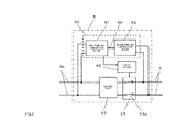
- FIG.2 is a block diagram showing the configuration of vehicle charging apparatus 6 of vehicle charging system 1 according to an embodiment of the present invention.
- vehicle charging apparatus 6 is disposed between residential power line 3a and vehicle power line 7, and is provided with low-pass filter 63 that attenuates a power line communication high-frequency signal, power line communication section 60 that is connected in parallel to low-pass filter 63, performs conversion to a signal of a frequency lower than that of a power line communication high-frequency signal superimposed on residential power line 3a from charge command apparatus 5 ( FIG.1 ), and communicates with vehicle 8 ( FIG.1 ) via vehicle power line 7 by means of the converted low-frequency signal, and control section 65 that controls connection or disconnection of connection section 64 based on a charge command apparatus 5 command signal demodulated by power line communication section 60.
- low-pass filter 63 that attenuates a power line communication high-frequency signal
- power line communication section 60 that is connected in parallel to low-pass filter 63, performs conversion to a signal of a frequency lower than that of a power line communication high-frequency signal superimposed on residential power line 3a from charge command apparatus 5 ( FIG.1 ), and communicates
- Power line communication section 60 is disposed on a bypass path that bypasses low-pass filter 63 and connection section 64.
- vehicle charging apparatus 6 outputs a power line communication high-frequency signal output from charge command apparatus 5 and superimposed on residential power line 3a to vehicle power line 7 after being attenuated by low-pass filter 63, enabling power line communication high-frequency signal leakage outside residence 2 to be impeded. Also, since power line communication section 60 performs conversion to a signal of a frequency lower than that of a power line communication high-frequency signal used inside residence 2 and communicates with vehicle 8 outside residence 2, leakage outside residence 2 of a power line communication signal used inside residence 2 can be impeded.
- Charge command apparatus 5 can control a vehicle charging apparatus 6 charging operation, and perform authentication by means of communication with vehicle 8 via vehicle charging apparatus 6. By this means, vehicle charging apparatus 6 can supply power to vehicle 8 via vehicle power line 7 based on a charge command apparatus 5 command. Specifically, charge command apparatus 5 issues a charging permission command to control section 65 of vehicle charging apparatus 6 only for a vehicle 8 for which authentication has been completed, and sends a charging non-permission command for an irregular vehicle 8 that has not been authenticated.
- Power line communication section 60 has first power line communication section 61 and second power line communication section 62, and first power line communication section 61 and second power line communication section 62 are connected via dedicated data line 66.
- First power line communication section 61 demodulates a power line communication high-frequency signal superimposed on residential power line 3a from charge command apparatus 5, and outputs this signal to dedicated data line 66.
- Connection section 64 comprises switch 64a, and performs connection or disconnection between residential power line 3a and vehicle power line 7 according to whether it is in a closed state or in an open state.
- Control section 65 receives a charge command apparatus 5 command signal demodulated by first power line communication section 61. Then control section 65 controls switch 64a of connection section 64 so as to be in a closed state (on state) when a received command signal is a charging permission signal, and to be in an open state (off state) when a received command signal is a charging non-permission signal.
- control section 65 controls switch 64a of connection section 64 so as to be in a closed state (on state) when a received command signal is a charging permission signal, and to be in an open state (off state) when a received command signal is a charging non-permission signal.
- First power line communication section 61 demodulates a command signal from charge command apparatus 5 and outputs this signal to dedicated data line 66, and, as described later herein, second power line communication section 62 modulates dedicated data line 66 data with a signal of a frequency (for example, a frequency of 10 kHz to 450 kHz) lower than that of a power line communication high-frequency signal (a signal with a frequency of 2 MHz to 30 MHz), and outputs this signal to vehicle power line 7.
- a frequency for example, a frequency of 10 kHz to 450 kHz
- a power line communication high-frequency signal a signal with a frequency of 2 MHz to 30 MHz
- power line noise in a high-frequency signal frequency band of 2 to 30 MHz is lower than power line noise in a low-frequency signal frequency band of 10 kHz to 450 kHz, and therefore a high-frequency signal transmission speed is higher than a low-frequency signal transmission speed.
- control section 65 performs control based on a charge command apparatus 5 command signal demodulated by first power line communication section 61.
- a charge command apparatus 5 command signal can be output from second power line communication section 62. If a command signal is output from second power line communication section 62, the command signal frequency falls, enabling radiation to be more easily suppressed, and signal leakage to vehicle power line 7 or the like via a control circuit to be suppressed.
- charge command apparatus 5 is a generally used personal computer or the like, it may be possible to perform communication with a power line communication apparatus other than vehicle charging apparatus 6.
- vehicle charging apparatus 6 when charge command apparatus 5 or that power line communication apparatus transmits a broadcast signal or multicast signal to residential power line 3a, vehicle charging apparatus 6 also receives that broadcast signal or that multicast signal.
- that broadcast signal or that multicast signal is not a signal addressed to vehicle charging apparatus 6, when that signal is passed from first power line communication section 61 to second power line communication section 62, a problem arises of second power line communication section 62 communication being slowed down because the band used for communication by second power line communication section 62 is smaller than the band used by first power line communication section 61.
- first power line communication section 61 analyzes the destination of a received broadcast signal or multicast signal, and does not transmit that signal to second power line communication section 62 if that destination is not vehicle charging apparatus 6. Analysis of the destination of a received broadcast signal or multicast signal is performed by first signal processing section 14 described later herein. If the destination of a received signal is not vehicle charging apparatus 6, first signal processing section 14 does not pass that signal to first dedicated communication section 15 (that is, does not pass that signal to second power line communication section 62). Therefore, that broadcast signal or that multicast signal is not converted to a power line communication low-frequency signal.
- first signal processing section 14 does not pass that signal to second power line communication section 62, and therefore that broadcast signal or that multicast signal is not converted to a power line communication low-frequency signal.
- connection section 64 Even when connection section 64 is in an open state, since power line communication section 60 is connected in parallel to low-pass filter 63, charge command apparatus 5 can communicate with vehicle 8 via vehicle charging apparatus 6, and can perform vehicle 8 authentication.
- low-pass filter 63 is here disposed between residential power line 3a and connection section 64, low-pass filter 63 may also be disposed between connection section 64 and vehicle power line 7. With this configuration, also, leakage via vehicle power line 7 into space outside residence 2 of a power line communication signal used inside residence 2 can be suppressed.
- FIG.3 is a block diagram showing the configuration of first power line communication section 61 of vehicle charging apparatus 6 according to an embodiment of the present invention
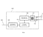
- FIG.4 is a block diagram showing the configuration of second power line communication section 62 of vehicle charging apparatus 6 according to an embodiment of the present invention.
- first power line communication section 61 has first coupler 12 connected to a residential power line 3a pair via capacitors 11, first modulation/demodulation section 13 that is connected to first coupler 12 and modulates or demodulates a signal, first signal processing section 14 that decodes a signal demodulated by first modulation/demodulation section 13, and first dedicated communication section 15 that is connected between first signal processing section 14 and dedicated data line 66 and transfers communication information decoded by first signal processing section 14 via dedicated data line 66. Also, first signal processing section 14 is connected to control section 65.
- second power line communication section 62 has second coupler 17 connected to a vehicle power line 7 pair via capacitors 16, second modulation/demodulation section 18 that is connected to second coupler 17 and modulates or demodulates a signal, second signal processing section 19 that decodes a signal demodulated by second modulation/demodulation section 18, and second dedicated communication section 20 that is connected between second signal processing section 19 and dedicated data line 66 and transfers communication information decoded by second signal processing section 19 via dedicated data line 66.
- First dedicated communication section 15 performs communication with second dedicated communication section 20 via Ethernet (registered trademark), fiber optic, or suchlike dedicated data line 66.
- First modulation/demodulation section 13 and second modulation/demodulation section 18 demodulate a communication signal superimposed on a power line (residential power line 3a or vehicle power line 7) and recover data, and also modulate data into a signal to be superimposed on a power line.
- First signal processing section 14 decomposes self-addressed necessary data from the data and sends this to control section 65, and also adds destination information and/or an error correction code to data sent from charge command apparatus 5 or electrical storage apparatus 10 and sends this data to first modulation/demodulation section 13 or second modulation/demodulation section 18.
- Transformers are used as first coupler 12 and second coupler 17.
- First dedicated communication section 15 outputs data (communication information) from first signal processing section 14 to dedicated data line 66.
- second dedicated communication section 20 outputs data (communication information) from second signal processing section 19 to dedicated data line 66. If Ethernet (registered trademark)) is used as dedicated data line 66, first dedicated communication section 15 and second dedicated communication section 20 convert data to an Ethernet (registered trademark) signal and output that signal.
- first power line communication section 61 and second power line communication section 62 perform communication operations at independent dedicated frequencies.
- first modulation/demodulation section 13 and second modulation/demodulation section 18 perform power line communication at different frequencies.
- Second modulation/demodulation section 18 uses a frequency (for example, a frequency of 10 kHz to 450 kHz) lower than a frequency (for example, a frequency of 2 MHz to 30 MHz) used by first modulation/demodulation section 13 to communicate with a device inside residence 2 as a frequency when performing power line communication.
- Performing communication after conversion to a signal of a frequency lower than that of a power line communication high-frequency signal superimposed on residential power line 3a makes radio wave leakage from vehicle power line 7 easier to suppress, and enables leakage of a power line communication signal into space outside residence 2 to be impeded.
- a power line communication high-frequency signal superimposed on residential power line 3a from charge command apparatus 5 is converted to a signal of a frequency lower than the frequency (for example, a frequency of 2 MHz to 30 MHz) used by first power line communication section 61 and second power line communication section 62 to communicate with a device inside residence 2, and is communicated to vehicle 8 outside residence 2 via vehicle power line 7.
- a low-frequency signal transmitted from vehicle 8 is superimposed on residential power line 3a as a high-frequency signal of a frequency (for example, a frequency of 2 MHz to 30 MHz) used to communicate with a device inside residence 2 via second power line communication section 62 and first power line communication section 61, and is transmitted to charge command apparatus 5.
- first modulation/demodulation section 13 and second modulation/demodulation section 18 are both disposed on a bypass path, but the same technological effect can also be achieved if at least one of first modulation/demodulation section 13 and second modulation/demodulation section 18 is disposed on a bypass path. That is to say, it is possible for a power line communication high-frequency signal transmitted from charge command apparatus 5 to be transmitted to the vehicle 8 side.
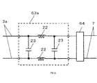
- FIG.5 is a block diagram showing a configuration of low-pass filter 63 of vehicle charging apparatus 6 in vehicle charging system 1 according to an embodiment of the present invention
- FIG.6 is a block diagram showing another configuration example of above low-pass filter 63
- FIG.7 is a block diagram showing yet another configuration example of above low-pass filter 63.
- low-pass filter 63 comprises a T filter balance circuit using inductors 21, inductors 22, and capacitor 23.
- low-pass filter 63 attenuates a power line communication high-frequency signal superimposed on residential power line 3a output from charge command apparatus 5 and outputs this attenuated signal to vehicle power line 7 via connection section 64, enabling leakage of a power line communication high-frequency signal into space outside residence 2 to be impeded.
- a power line communication high-frequency signal superimposed on vehicle power line 7 output from vehicle 8 is also attenuated before being output to residential power line 3a by having low-pass filter 63 configured as a T filter, interference with, for example, low-speed power line carrier frequency communication used for some time as a home automation communication means can be reduced, and the introduction of high-frequency noise (for example, vehicle charging apparatus noise or the like) from outside residence 2 can be suppressed.
- high-frequency noise for example, vehicle charging apparatus noise or the like
- Low-pass filter 63 is not limited to a T filter, and a variety of variations are possible according to the input/output impedance.
- the configurations shown in FIG.6 and FIG.7 may also be used. That is to say, a pi filter balance circuit configuration may be used as in the case of low-pass filter 63a shown in FIG.6 , or an L filter balance circuit configuration may be used as in the case of low-pass filter 63b shown in FIG.7 .
- FIG.8 is a flowchart explaining the operation of vehicle charging system 1 according to an embodiment of the present invention.
- vehicle 8 connection is detected by vehicle power line 7 of vehicle charging apparatus 6 being inserted in power socket 9 of vehicle 8 (S100, S102).
- charge command apparatus 5 and vehicle 8 perform an authentication operation.
- control information is transmitted from charge command apparatus 5 to vehicle charging apparatus 6 based on the authentication result (S104).
- vehicle charging apparatus 6 performs relay processing of authentication related information transferred between charge command apparatus 5 and vehicle 8 (a MAC address of power line communication section 4 of charge command apparatus 5 and a MAC address of a power line communication apparatus (not shown) of vehicle 8, or the like), and after completing authentication processing, performs reception processing of control information transmitted from charge command apparatus 5.
- vehicle charging system 1 controls switch 64a of connection section 64 by means of vehicle charging apparatus 6 so as to be in a closed state (S106, S108). (S104) through (S108) are executed repeatedly until charging of vehicle 8 is completed.
- vehicle charging system 1 controls switch 64a of connection section 64 so as to be in an open state (S106, S110). By this means, the power supply from vehicle charging apparatus 6 is stopped.
- vehicle charging apparatus 6 is disposed between residential power line 3a and vehicle power line 7, and is provided with low-pass filter 63 that attenuates a power line communication high-frequency signal, power line communication section 60 that is connected in parallel to low-pass filter 63, performs conversion to a signal of a frequency lower than that of a power line communication high-frequency signal superimposed on residential power line 3a from charge command apparatus 5, and communicates with vehicle 8 via vehicle power line 7 by means of the converted low-frequency signal, and control section 65 that controls connection or disconnection of connection section 64 based on a charge command apparatus 5 command signal demodulated by power line communication section 60.
- vehicle charging apparatus 6 outputs a power line communication high-frequency signal output from charge command apparatus 5 and superimposed on residential power line 3a to vehicle power line 7 after being attenuated by low-pass filter 63 even when charge command apparatus 5 inside residence 2 performs power line communication with vehicle 8 via vehicle charging apparatus 6, enabling power line communication high-frequency signal leakage into space outside residence 2 to be impeded. Also, since power line communication section 60 performs conversion to a signal of a frequency lower than that of a power line communication high-frequency signal used inside residence 2 and communicates with vehicle 8 outside residence 2, power line communication signal leakage outside residence 2 can be impeded.
- vehicle charging system 1 is provided with above-described vehicle charging apparatus 6 and charge command apparatus 5 that communicates with vehicle charging apparatus 6 via residential power line 3a, and vehicle charging apparatus 6 supplies power to vehicle 8 from residential power line 3a based on a charge command apparatus 5 command, power line communication signal leakage into space outside residence 2 can be impeded even when charge command apparatus 5 inside residence 2 performs power line communication with vehicle 8 via vehicle charging apparatus 6.
- a similar effect can be obtained by keeping a frequency modulated or demodulated by second power line communication section 62 at a frequency used for communication with a device inside residence 2 (for example, a frequency of 2 MHz to 30 MHz), making the transmission signal level of that transmission signal and a modulation section installed in the vehicle charging apparatus a low transmission signal level of wall attenuation 10 to 20 dB of a typical residence (for example, in the case of a frequency of 2 MHz to 30 MHz) or more, and making this a normal transmission level for the first power line communication section.
- a frequency modulated or demodulated by second power line communication section 62 at a frequency used for communication with a device inside residence 2 (for example, a frequency of 2 MHz to 30 MHz), making the transmission signal level of that transmission signal and a modulation section installed in the vehicle charging apparatus a low transmission signal level of wall attenuation 10 to 20 dB of a typical residence (for example, in the case of a frequency of 2 MHz to 30 MHz) or more
- an electric vehicle has been described as an example, but the present invention is not limited to this, and can also be applied to a hybrid vehicle that uses both a motor and an engine.
- vehicle charging apparatus 6 that performs frequency conversion in power line communication executed between an indoor power line communication apparatus (charge command apparatus 5) and outdoor vehicle 8, but it is also possible for vehicle charging apparatus 6 to be applied to a case in which a power line that transmits a power line communication high-frequency signal (equivalent to residential power line 3a in the above embodiment) is disposed underground.
- a communication circuit or the like capable of performing radio communication should be used instead of the second power line communication section, and if a power line communication high-frequency signal is converted to a low-frequency signal for a dedicated communication line, a communication circuit supporting that dedicated communication line should be used.
- a power line communication high-frequency signal that is output from a charge command apparatus and superimposed on a residential power line is output to a vehicle power line after being attenuated by means of a low-pass filter, enabling leakage of a power line communication high-frequency signal outside a residence to be impeded.
- a power line communication section when communicating with a vehicle outside a residence, performs conversion to a signal of a frequency lower than that of a power line communication high-frequency signal used inside the residence, enabling power line communication signal leakage outside the residence to be impeded.
- the present invention is suitable for use in a vehicle charging apparatus that supplies power to a vehicle such as an electric vehicle or hybrid vehicle that runs by charging an electrical storage apparatus with power and using that stored power to rotate the wheels, and a vehicle charging system that uses this.
Abstract
Description
- The present invention relates to a power supply apparatus that supplies power to a vehicle that incorporates an electrical storage apparatus and a motor that rotates the wheels, and drives the motor using power of the electrical storage apparatus, and a vehicle charging system that uses this.
- In recent years, attention has continued to been drawn to an electric vehicle that incorporates an electrical storage apparatus and a motor that rotates the wheels, and drives the motor using power of the electrical storage apparatus, as an environment-friendly vehicle. With a vehicle of this kind, power is supplied to a power line from a vehicle charging apparatus outside the body of the vehicle, and the supplied power is stored in the electrical storage apparatus (see
Patent Literature 1, for example). - PTL1
Japanese Patent Application Laid-Open No.2009-171700 - In the case of a typical residence, a vehicle charging apparatus is connected to a power line of a power source inside the residence, and charging power is supplied to a vehicle using power of the power source inside the residence.
- However, a problem is that, when a charge command apparatus inside a residence superimposes a high-frequency signal on a power line and performs power line communication with a vehicle via a vehicle charging apparatus, a power line communication high-frequency signal output from the charge command apparatus is prone to leak outside the residence via the power line.
- It is thus an object of the present invention to impede leakage of a power line communication high-frequency signal outside a residence even when a charge command apparatus inside the residence performs power line communication with a vehicle via a vehicle charging apparatus.
- A power supply apparatus according to a first aspect of the present invention performs supplying of power to a device having a second power line communication apparatus that performs communication with a first power line communication apparatus via a power line, and employs a configuration having: a receiving section that receives a first signal that is transmitted from the first power line communication apparatus and has a first frequency via the power line; a frequency conversion section that converts the first signal to a second signal having a second frequency lower than the first frequency; and a transmitting section that transmits the second signal to the second power line communication apparatus via the power line.
- According to this configuration, by converting a first signal having a first frequency to a second signal having a frequency lower than that first frequency and transmitting this second signal to a device, signal leakage in power line communication between the first power line communication apparatus and the device can be reduced.
- A power supply apparatus according to a second aspect of the present invention employs a configuration whereby the first signal has control information relating to supplying of power performed by that power supply apparatus.
- According to this configuration, by transmitting control information relating to supplying of power as a first signal, it is possible to control supplying of power performed by that power supply apparatus.
- A power supply apparatus according to a third aspect of the present invention employs a configuration whereby the first signal has information relating to authentication for authenticating the device.
- According to this configuration, by transmitting information relating to authentication for authenticating the device as a first signal, it is possible to authenticate the device.
- A power supply apparatus according to a fourth aspect of the present invention employs a configuration further having: a connection section that places the power line in a disconnected state or a connected state; and a control section that controls the connection section based on at least one of the first signal and the second signal.
- According to this configuration, by controlling the power line so as to be in a connected state or a disconnected state based on at least one of the first signal and the second signal, it is possible to control the power supply to a device.
- A power supply apparatus according to a fifth aspect of the present invention employs a configuration further having: a cutoff section that passes the power and cuts off the first signal; and a bypass section that bypasses the cutoff section and the connection section; wherein at least one of the receiving section, the frequency conversion section, and the transmitting section is disposed in the bypass section.
- According to this configuration, the power line can transmit the first signal and the second signal even when the power line is in a disconnected state. That is to say, it is possible to perform supplying of power to a device and transmission of the first signal and second signal independently.
- A power supply apparatus according to a sixth aspect of the present invention employs a configuration wherein the cutoff section is a low-pass filter.
- A power supply apparatus according to a seventh aspect of the present invention employs a configuration wherein the low-pass filter is a T filter, a pi filter, or an L filter, composed of an inductor and a capacitor,
- A power supply apparatus according to an eighth aspect of the present invention employs a configuration whereby: the first power line communication apparatus stores charging permission information permitting charging of the device in the first signal when authentication for the device succeeds; and the control section controls the connection section so that the power line enters a connected state based on the charging permission information.
- According to this configuration, since the connection section is controlled so that the power line enters a connected state based on charging permission information stored in the first signal, charging of the device can be performed only when device authentication succeeds, making it possible to prevent electricity theft and so forth.
- A power supply apparatus according to a ninth aspect of the present invention employs a configuration whereby: the first power line communication apparatus stores charging non-permission information that does not permit charging of the device in the first signal when authentication for the device fails; and the control section controls the connection section so that the power line enters a disconnected state based on the charging non-permission information.
- According to this configuration, since the connection section is controlled so that the power line enters a disconnected state based on charging non-permission information stored in the first signal, charging of the device is not performed when device authentication fails, making it possible to prevent electricity theft and so forth.
- A power supply apparatus according to a tenth aspect of the present invention employs a configuration whereby: the first signal is a first multicarrier signal using a first frequency band; the second signal is a second multicarrier signal using a second frequency band narrower than the first frequency band; and the frequency conversion section does not perform conversion to the second multicarrier signal for the first multicarrier signal when the destination of a first multicarrier signal received by the receiving section differs from that power supply apparatus.
- If a first multicarrier signal is converted to a second multicarrier signal when the destination of a first multicarrier signal received by the receiving section differs from that power supply apparatus, a second frequency band that is relatively narrower than the first frequency band is used needlessly. Thus, according to this configuration, the frequency conversion section does not perform conversion to a second multicarrier signal in this case, making it possible to utilize the second frequency band efficiently.
- A power supply apparatus according to an eleventh aspect of the present invention employs a configuration whereby: the first signal is a first multicarrier signal using a first frequency band; the second signal is a second multicarrier signal using a second frequency band narrower than the first frequency band; and the frequency conversion section does not perform conversion to the second multicarrier signal for the first multicarrier signal when the destination of a first multicarrier signal received by the receiving section differs from the second power line communication apparatus.
- If a first multicarrier signal is converted to a second multicarrier signal when the destination of the first multicarrier signal differs from the second power line communication apparatus, a second frequency band that is relatively narrower than the first frequency band is used needlessly. Thus, according to this configuration, the frequency conversion section does not perform conversion to a second multicarrier signal in this case, making it possible to utilize the second frequency band efficiently.
- A vehicle charging system according to a twelfth aspect of the present invention employs a configuration having: one of the above-described power supply apparatuses; the first power line communication apparatus; and a vehicle having the second power line communication apparatus.
- According to this configuration, power line communication signal leakage can be reduced in power line communication performed between a first power line communication apparatus and a vehicle at the time of authentication or during charging.
- According to the present invention, a power line communication high-frequency signal superimposed on a residential power line output from a charge command apparatus is output to a vehicle power line after being attenuated by means of a low-pass filter, enabling power line communication high-frequency signal leakage outside the residence to be impeded. Also, the power line communication section performs conversion to a signal of a frequency lower than that of a power line communication high-frequency signal used inside a residence and communicates with a vehicle outside the residence, enabling power line communication signal leakage outside the residence to be impeded.
- In addition, according to the present invention, power from a residential power line is supplied to a vehicle based on a charge command apparatus command, enabling power line communication signal leakage outside a residence to be impeded even when a charge command apparatus inside the residence performs power line communication with the vehicle via a vehicle charging apparatus.
-
-
FIG.1 is a configuration diagram of a vehicle charging system according to an embodiment of the present invention; -
FIG.2 is a block diagram showing the configuration of a vehicle charging apparatus of the above vehicle charging system; -
FIG.3 is a block diagram showing the configuration of a first power line communication section of a vehicle charging apparatus in the above vehicle charging system; -
FIG.4 is a block diagram showing the configuration of a second power line communication section of a vehicle charging apparatus in the above vehicle charging system; -
FIG.5 is a block diagram showing a configuration of a low-pass filter of a vehicle charging apparatus in the above vehicle charging system; -
FIG.6 is a block diagram showing another configuration example of a low-pass filter of a vehicle charging apparatus in the above vehicle charging system; -
FIG.7 is a block diagram showing yet another configuration example of a low-pass filter of a vehicle charging apparatus in the above vehicle charging system; and -
FIG.8 is a flowchart explaining the operation of the above vehicle charging system. - Now, an embodiment of the present invention will be described with reference to the accompanying drawings. In the drawings, identical or equivalent parts are assigned the same reference codes.
- First, a vehicle charging system according to an embodiment of the present invention will be described with reference to
FIG.1 through FIG.8 . Here, a case is described by way of example in which an electric vehicle incorporates an electrical storage apparatus and a motor that rotates the wheels, and drives the motor using power stored in the electrical storage apparatus. With an electric vehicle, power stored in the electrical storage apparatus is supplied to the motor and the wheels are rotated by the motor, enabling the vehicle to move to another place. -
FIG.1 is a configuration diagram ofvehicle charging system 1 according to an embodiment of the present invention. InFIG.1 ,vehicle charging system 1 is provided withcharge command apparatus 5 incorporated in powerline communication section 4, vehicle charging apparatus 6, andvehicle 8 connected to vehicle charging apparatus 6 viavehicle power line 7. - In
typical residence 2,charge command apparatus 5 and vehicle charging apparatus 6 are connected topower source 3 ofresidence 2. By this means, necessary power is supplied to vehicle charging apparatus 6 frompower source 3 ofresidence 2. Vehicle charging apparatus 6 supplies power tovehicle 8 using power ofpower source 3 ofresidence 2. - In
vehicle charging system 1, aftervehicle power line 7 is inserted inpower socket 9 ofvehicle 8,vehicle 8 authentication is performed bycharge command apparatus 5, and power is supplied tovehicle 8 only if authentication is successful.Vehicle 8 chargeselectrical storage apparatus 10 installed invehicle body 8a with power supplied viapower socket 9. -
Charge command apparatus 5 is configured as a dedicated device. A personal computer may also be used instead of a dedicated device. Via built-in powerline communication section 4,charge command apparatus 5 uses thepower source 3 power line to perform power line communication with vehicle charging apparatus 6. - Vehicle charging apparatus 6 is connected to
residential power line 3a ofpower source 3 insideresidence 2, and supplies charging power tovehicle 8 using power ofpower source 3 insideresidence 2. - However, since power line communication is performed with
vehicle 8 via vehicle charging apparatus 6 with a high-frequency signal superimposed onresidential power line 3a bycharge command apparatus 5 insideresidence 2, a high-frequency signal of power line communication performed viaresidential power line 3a insideresidence 2 is prone to leakage outsideresidence 2. A frequency of 2 MHz to 30 MHz, for example, is used as the frequency of a signal used in power line communication, and high-speed communication can be performed by means of such a high-frequency signal. - Thus, in this embodiment, leakage of a power line communication high-frequency signal outside
residence 2 is impeded by means of the configuration of vehicle charging apparatus 6 shown inFIG.2 even whencharge command apparatus 5 insideresidence 2 performs power line communication withvehicle 8 via vehicle charging apparatus 6. - Vehicle charging apparatus 6 is not limited to charging a hybrid vehicle or electric vehicle, and may also charge a motorcycle or car with a built-in battery, or an actual electrical device or battery that requires charging.
- Also, a power line communication high-frequency signal transmitted by
charge command apparatus 5 is authentication information used to perform authentication forvehicle 8 or control information for controlling vehicle charging performed by vehicle charging apparatus 6. - Specifically, authentication information is address information (a MAC address or the like) held by power
line communication section 4. - Also, specifically, control information is a charge command signal transmitted to control
section 65 described later herein or a confirmation signal for confirming the charge status ofvehicle 8. -
FIG.2 is a block diagram showing the configuration of vehicle charging apparatus 6 ofvehicle charging system 1 according to an embodiment of the present invention. - That is to say, vehicle charging apparatus 6 is disposed between
residential power line 3a andvehicle power line 7, and is provided with low-pass filter 63 that attenuates a power line communication high-frequency signal, powerline communication section 60 that is connected in parallel to low-pass filter 63, performs conversion to a signal of a frequency lower than that of a power line communication high-frequency signal superimposed onresidential power line 3a from charge command apparatus 5 (FIG.1 ), and communicates with vehicle 8 (FIG.1 ) viavehicle power line 7 by means of the converted low-frequency signal, andcontrol section 65 that controls connection or disconnection ofconnection section 64 based on acharge command apparatus 5 command signal demodulated by powerline communication section 60. - Power
line communication section 60 is disposed on a bypass path that bypasses low-pass filter 63 andconnection section 64. - By means of this configuration, vehicle charging apparatus 6 outputs a power line communication high-frequency signal output from
charge command apparatus 5 and superimposed onresidential power line 3a tovehicle power line 7 after being attenuated by low-pass filter 63, enabling power line communication high-frequency signal leakage outsideresidence 2 to be impeded. Also, since powerline communication section 60 performs conversion to a signal of a frequency lower than that of a power line communication high-frequency signal used insideresidence 2 and communicates withvehicle 8 outsideresidence 2, leakage outsideresidence 2 of a power line communication signal used insideresidence 2 can be impeded. -
Charge command apparatus 5 can control a vehicle charging apparatus 6 charging operation, and perform authentication by means of communication withvehicle 8 via vehicle charging apparatus 6. By this means, vehicle charging apparatus 6 can supply power tovehicle 8 viavehicle power line 7 based on acharge command apparatus 5 command. Specifically,charge command apparatus 5 issues a charging permission command to controlsection 65 of vehicle charging apparatus 6 only for avehicle 8 for which authentication has been completed, and sends a charging non-permission command for anirregular vehicle 8 that has not been authenticated. - Power
line communication section 60 has first powerline communication section 61 and second powerline communication section 62, and first powerline communication section 61 and second powerline communication section 62 are connected viadedicated data line 66. First powerline communication section 61 demodulates a power line communication high-frequency signal superimposed onresidential power line 3a fromcharge command apparatus 5, and outputs this signal todedicated data line 66. -
Connection section 64 comprisesswitch 64a, and performs connection or disconnection betweenresidential power line 3a andvehicle power line 7 according to whether it is in a closed state or in an open state. -
Control section 65 receives acharge command apparatus 5 command signal demodulated by first powerline communication section 61. Then controlsection 65 controls switch 64a ofconnection section 64 so as to be in a closed state (on state) when a received command signal is a charging permission signal, and to be in an open state (off state) when a received command signal is a charging non-permission signal. By this means, it is possible forvehicle charging system 1 not to supply power to anirregular vehicle 8, enabling electricity theft to be prevented. - First power
line communication section 61 demodulates a command signal fromcharge command apparatus 5 and outputs this signal todedicated data line 66, and, as described later herein, second powerline communication section 62 modulates dedicateddata line 66 data with a signal of a frequency (for example, a frequency of 10 kHz to 450 kHz) lower than that of a power line communication high-frequency signal (a signal with a frequency of 2 MHz to 30 MHz), and outputs this signal tovehicle power line 7. By this means, leakage of a power line communication high-frequency signal used insideresidence 2 into space outsideresidence 2 viavehicle power line 7 can be suppressed, since radiation tends to be suppressed in the case of a low-frequency signal. - Generally, power line noise in a high-frequency signal frequency band of 2 to 30 MHz is lower than power line noise in a low-frequency signal frequency band of 10 kHz to 450 kHz, and therefore a high-frequency signal transmission speed is higher than a low-frequency signal transmission speed.
- Also,
control section 65 performs control based on acharge command apparatus 5 command signal demodulated by first powerline communication section 61. - It is also possible for a
charge command apparatus 5 command signal to be output from second powerline communication section 62. If a command signal is output from second powerline communication section 62, the command signal frequency falls, enabling radiation to be more easily suppressed, and signal leakage tovehicle power line 7 or the like via a control circuit to be suppressed. - If
charge command apparatus 5 is a generally used personal computer or the like, it may be possible to perform communication with a power line communication apparatus other than vehicle charging apparatus 6. In this case, whencharge command apparatus 5 or that power line communication apparatus transmits a broadcast signal or multicast signal toresidential power line 3a, vehicle charging apparatus 6 also receives that broadcast signal or that multicast signal. However, if that broadcast signal or that multicast signal is not a signal addressed to vehicle charging apparatus 6, when that signal is passed from first powerline communication section 61 to second powerline communication section 62, a problem arises of second powerline communication section 62 communication being slowed down because the band used for communication by second powerline communication section 62 is smaller than the band used by first powerline communication section 61. Thus, first powerline communication section 61 analyzes the destination of a received broadcast signal or multicast signal, and does not transmit that signal to second powerline communication section 62 if that destination is not vehicle charging apparatus 6. Analysis of the destination of a received broadcast signal or multicast signal is performed by firstsignal processing section 14 described later herein. If the destination of a received signal is not vehicle charging apparatus 6, firstsignal processing section 14 does not pass that signal to first dedicated communication section 15 (that is, does not pass that signal to second power line communication section 62). Therefore, that broadcast signal or that multicast signal is not converted to a power line communication low-frequency signal. - Similarly, if the destination of a broadcast signal or multicast signal transmitted by
charge command apparatus 5 or that power line communication apparatus is not second powerline communication section 62, firstsignal processing section 14 does not pass that signal to second powerline communication section 62, and therefore that broadcast signal or that multicast signal is not converted to a power line communication low-frequency signal. - Even when
connection section 64 is in an open state, since powerline communication section 60 is connected in parallel to low-pass filter 63,charge command apparatus 5 can communicate withvehicle 8 via vehicle charging apparatus 6, and can performvehicle 8 authentication. - Also, although low-
pass filter 63 is here disposed betweenresidential power line 3a andconnection section 64, low-pass filter 63 may also be disposed betweenconnection section 64 andvehicle power line 7. With this configuration, also, leakage viavehicle power line 7 into space outsideresidence 2 of a power line communication signal used insideresidence 2 can be suppressed. - Next, actual configurations of first power
line communication section 61 and second powerline communication section 62 of powerline communication section 60 in vehicle charging apparatus 6 will be described with reference toFIG.3 andFIG.4 .FIG.3 is a block diagram showing the configuration of first powerline communication section 61 of vehicle charging apparatus 6 according to an embodiment of the present invention, andFIG.4 is a block diagram showing the configuration of second powerline communication section 62 of vehicle charging apparatus 6 according to an embodiment of the present invention. - As shown in
FIG.3 , first powerline communication section 61 hasfirst coupler 12 connected to aresidential power line 3a pair viacapacitors 11, first modulation/demodulation section 13 that is connected tofirst coupler 12 and modulates or demodulates a signal, firstsignal processing section 14 that decodes a signal demodulated by first modulation/demodulation section 13, and firstdedicated communication section 15 that is connected between firstsignal processing section 14 anddedicated data line 66 and transfers communication information decoded by firstsignal processing section 14 viadedicated data line 66. Also, firstsignal processing section 14 is connected to controlsection 65. - As shown in
FIG.4 , second powerline communication section 62 hassecond coupler 17 connected to avehicle power line 7 pair viacapacitors 16, second modulation/demodulation section 18 that is connected tosecond coupler 17 and modulates or demodulates a signal, secondsignal processing section 19 that decodes a signal demodulated by second modulation/demodulation section 18, and seconddedicated communication section 20 that is connected between secondsignal processing section 19 anddedicated data line 66 and transfers communication information decoded by secondsignal processing section 19 viadedicated data line 66. - First
dedicated communication section 15 performs communication with seconddedicated communication section 20 via Ethernet (registered trademark), fiber optic, or suchlikededicated data line 66. - First modulation/
demodulation section 13 and second modulation/demodulation section 18 demodulate a communication signal superimposed on a power line (residential power line 3a or vehicle power line 7) and recover data, and also modulate data into a signal to be superimposed on a power line. Firstsignal processing section 14 decomposes self-addressed necessary data from the data and sends this to controlsection 65, and also adds destination information and/or an error correction code to data sent fromcharge command apparatus 5 orelectrical storage apparatus 10 and sends this data to first modulation/demodulation section 13 or second modulation/demodulation section 18. - Transformers are used as
first coupler 12 andsecond coupler 17. Firstdedicated communication section 15 outputs data (communication information) from firstsignal processing section 14 todedicated data line 66. Similarly, seconddedicated communication section 20 outputs data (communication information) from secondsignal processing section 19 todedicated data line 66. If Ethernet (registered trademark)) is used asdedicated data line 66, firstdedicated communication section 15 and seconddedicated communication section 20 convert data to an Ethernet (registered trademark) signal and output that signal. - In this embodiment, first power
line communication section 61 and second powerline communication section 62 perform communication operations at independent dedicated frequencies. - Specifically, first modulation/
demodulation section 13 and second modulation/demodulation section 18 perform power line communication at different frequencies. Second modulation/demodulation section 18 uses a frequency (for example, a frequency of 10 kHz to 450 kHz) lower than a frequency (for example, a frequency of 2 MHz to 30 MHz) used by first modulation/demodulation section 13 to communicate with a device insideresidence 2 as a frequency when performing power line communication. Performing communication after conversion to a signal of a frequency lower than that of a power line communication high-frequency signal superimposed onresidential power line 3a makes radio wave leakage fromvehicle power line 7 easier to suppress, and enables leakage of a power line communication signal into space outsideresidence 2 to be impeded. - Thus, a power line communication high-frequency signal superimposed on
residential power line 3a fromcharge command apparatus 5 is converted to a signal of a frequency lower than the frequency (for example, a frequency of 2 MHz to 30 MHz) used by first powerline communication section 61 and second powerline communication section 62 to communicate with a device insideresidence 2, and is communicated tovehicle 8 outsideresidence 2 viavehicle power line 7. On the other hand, a low-frequency signal transmitted fromvehicle 8 is superimposed onresidential power line 3a as a high-frequency signal of a frequency (for example, a frequency of 2 MHz to 30 MHz) used to communicate with a device insideresidence 2 via second powerline communication section 62 and first powerline communication section 61, and is transmitted to chargecommand apparatus 5. - By this means, leakage of a power line communication signal into space outside
residence 2 can be impeded even whencharge command apparatus 5 insideresidence 2 performs power line communication withvehicle 8 via vehicle charging apparatus 6. - In the above embodiment, an example has been described in which first modulation/
demodulation section 13 and second modulation/demodulation section 18 are both disposed on a bypass path, but the same technological effect can also be achieved if at least one of first modulation/demodulation section 13 and second modulation/demodulation section 18 is disposed on a bypass path. That is to say, it is possible for a power line communication high-frequency signal transmitted fromcharge command apparatus 5 to be transmitted to thevehicle 8 side. - Next, actual configurations of low-
pass filter 63 in vehicle charging apparatus 6 will be described with reference toFIG.5 through FIG.7 . -
FIG.5 is a block diagram showing a configuration of low-pass filter 63 of vehicle charging apparatus 6 invehicle charging system 1 according to an embodiment of the present invention,FIG.6 is a block diagram showing another configuration example of above low-pass filter 63, andFIG.7 is a block diagram showing yet another configuration example of above low-pass filter 63. - As shown in
FIG.5 , low-pass filter 63 comprises a T filter balancecircuit using inductors 21,inductors 22, andcapacitor 23. By this means, low-pass filter 63 attenuates a power line communication high-frequency signal superimposed onresidential power line 3a output fromcharge command apparatus 5 and outputs this attenuated signal tovehicle power line 7 viaconnection section 64, enabling leakage of a power line communication high-frequency signal into space outsideresidence 2 to be impeded. Also, since a power line communication high-frequency signal superimposed onvehicle power line 7 output fromvehicle 8 is also attenuated before being output toresidential power line 3a by having low-pass filter 63 configured as a T filter, interference with, for example, low-speed power line carrier frequency communication used for some time as a home automation communication means can be reduced, and the introduction of high-frequency noise (for example, vehicle charging apparatus noise or the like) fromoutside residence 2 can be suppressed. - Low-
pass filter 63 is not limited to a T filter, and a variety of variations are possible according to the input/output impedance. For example, the configurations shown inFIG.6 andFIG.7 may also be used. That is to say, a pi filter balance circuit configuration may be used as in the case of low-pass filter 63a shown inFIG.6 , or an L filter balance circuit configuration may be used as in the case of low-pass filter 63b shown inFIG.7 . - Through the use of any of these filters, a high-frequency signal superimposed on
residential power line 3a is attenuated and is impeded from leaking outsideresidence 2. - Next, the operation of
vehicle charging system 1 will be described with reference toFIG.1 ,FIG.2 , andFIG.8. FIG.8 is a flowchart explaining the operation ofvehicle charging system 1 according to an embodiment of the present invention. - First, in
vehicle charging system 1,vehicle 8 connection is detected byvehicle power line 7 of vehicle charging apparatus 6 being inserted inpower socket 9 of vehicle 8 (S100, S102). - Next, when connection of
vehicle 8 is detected invehicle charging system 1,charge command apparatus 5 andvehicle 8 perform an authentication operation. Invehicle charging system 1, control information is transmitted fromcharge command apparatus 5 to vehicle charging apparatus 6 based on the authentication result (S104). - In S104, vehicle charging apparatus 6 performs relay processing of authentication related information transferred between
charge command apparatus 5 and vehicle 8 (a MAC address of powerline communication section 4 ofcharge command apparatus 5 and a MAC address of a power line communication apparatus (not shown) ofvehicle 8, or the like), and after completing authentication processing, performs reception processing of control information transmitted fromcharge command apparatus 5. - When control information is charging permission information,
vehicle charging system 1 controls switch 64a ofconnection section 64 by means of vehicle charging apparatus 6 so as to be in a closed state (S106, S108). (S104) through (S108) are executed repeatedly until charging ofvehicle 8 is completed. - On the other hand, if control information is charging non-permission information,
vehicle charging system 1 controls switch 64a ofconnection section 64 so as to be in an open state (S106, S110). By this means, the power supply from vehicle charging apparatus 6 is stopped. - As described above, according to this embodiment, as shown in
FIG.1 andFIG.2 , vehicle charging apparatus 6 is disposed betweenresidential power line 3a andvehicle power line 7, and is provided with low-pass filter 63 that attenuates a power line communication high-frequency signal, powerline communication section 60 that is connected in parallel to low-pass filter 63, performs conversion to a signal of a frequency lower than that of a power line communication high-frequency signal superimposed onresidential power line 3a fromcharge command apparatus 5, and communicates withvehicle 8 viavehicle power line 7 by means of the converted low-frequency signal, andcontrol section 65 that controls connection or disconnection ofconnection section 64 based on acharge command apparatus 5 command signal demodulated by powerline communication section 60. - By means of this configuration, vehicle charging apparatus 6 outputs a power line communication high-frequency signal output from
charge command apparatus 5 and superimposed onresidential power line 3a tovehicle power line 7 after being attenuated by low-pass filter 63 even whencharge command apparatus 5 insideresidence 2 performs power line communication withvehicle 8 via vehicle charging apparatus 6, enabling power line communication high-frequency signal leakage into space outsideresidence 2 to be impeded. Also, since powerline communication section 60 performs conversion to a signal of a frequency lower than that of a power line communication high-frequency signal used insideresidence 2 and communicates withvehicle 8 outsideresidence 2, power line communication signal leakage outsideresidence 2 can be impeded. - Also, since
vehicle charging system 1 is provided with above-described vehicle charging apparatus 6 andcharge command apparatus 5 that communicates with vehicle charging apparatus 6 viaresidential power line 3a, and vehicle charging apparatus 6 supplies power tovehicle 8 fromresidential power line 3a based on acharge command apparatus 5 command, power line communication signal leakage into space outsideresidence 2 can be impeded even whencharge command apparatus 5 insideresidence 2 performs power line communication withvehicle 8 via vehicle charging apparatus 6. - An actual configuration of the present invention is not limited to the above-described embodiment, and various variations and modifications may be possible without departing from the scope of the present invention.
- For example, since it is an object of the present invention to prevent loss of communication quality between a vehicle charging apparatus and charge command apparatus and reduce power line communication signal radiation from a vehicle power line, a similar effect can be obtained by keeping a frequency modulated or demodulated by second power
line communication section 62 at a frequency used for communication with a device inside residence 2 (for example, a frequency of 2 MHz to 30 MHz), making the transmission signal level of that transmission signal and a modulation section installed in the vehicle charging apparatus a low transmission signal level ofwall attenuation 10 to 20 dB of a typical residence (for example, in the case of a frequency of 2 MHz to 30 MHz) or more, and making this a normal transmission level for the first power line communication section. - Also, an electric vehicle has been described as an example, but the present invention is not limited to this, and can also be applied to a hybrid vehicle that uses both a motor and an engine.
- Furthermore, in the above embodiment a description has been given of vehicle charging apparatus 6 that performs frequency conversion in power line communication executed between an indoor power line communication apparatus (charge command apparatus 5) and
outdoor vehicle 8, but it is also possible for vehicle charging apparatus 6 to be applied to a case in which a power line that transmits a power line communication high-frequency signal (equivalent toresidential power line 3a in the above embodiment) is disposed underground. - Moreover, in the above embodiment an example has been described in which a power line communication high-frequency signal is converted to a power line communication low-frequency signal, but conversion may also be performed to a radio communication low-frequency signal or a low-frequency signal for a dedicated communication line instead of a power line communication low-frequency signal.
- If a power line communication high-frequency signal is converted to a radio communication low-frequency signal, a communication circuit or the like capable of performing radio communication should be used instead of the second power line communication section, and if a power line communication high-frequency signal is converted to a low-frequency signal for a dedicated communication line, a communication circuit supporting that dedicated communication line should be used.
- The disclosure of Japanese Patent Application No.
2010-004720, filed on January 13, 2010 - In the present invention, a power line communication high-frequency signal that is output from a charge command apparatus and superimposed on a residential power line is output to a vehicle power line after being attenuated by means of a low-pass filter, enabling leakage of a power line communication high-frequency signal outside a residence to be impeded. Also, when communicating with a vehicle outside a residence, a power line communication section performs conversion to a signal of a frequency lower than that of a power line communication high-frequency signal used inside the residence, enabling power line communication signal leakage outside the residence to be impeded.
- Thus, the present invention is suitable for use in a vehicle charging apparatus that supplies power to a vehicle such as an electric vehicle or hybrid vehicle that runs by charging an electrical storage apparatus with power and using that stored power to rotate the wheels, and a vehicle charging system that uses this.
-
- 1
- Vehicle charging system
- 2
- Residence
- 3
- Power source
- 3a
- Residential power line
- 4, 60
- Power line communication section
- 5
- Charge command apparatus
- 6
- Vehicle charging apparatus
- 7
- Vehicle power line
- 8
- Vehicle
- 8a
- Vehicle body
- 9
- Power socket
- 10
- Electrical storage apparatus
- 11, 16, 23
- Capacitor
- 12
- First coupler
- 13
- First modulation/demodulation section
- 14
- First signal processing section
- 15
- First dedicated communication section
- 17
- Second coupler
- 18
- Second modulation/demodulation section
- 19
- Second signal processing section
- 20
- Second dedicated communication section
- 21, 22
- Inductor
- 61
- First power line communication section
- 62
- Second power line communication section
- 63, 63a, 63b
- Low-pass filter
- 64
- Connection section
- 64a
- Switch
- 65
- Control section
- 66
- Dedicated data line
Claims (12)
- A power supply apparatus that performs supplying of power to a device having a second power line communication apparatus that performs communication with a first power line communication apparatus via a power line, the power supply apparatus comprising:a receiving section that receives a first signal that is transmitted from the first power line communication apparatus and has a first frequency via the power line;a frequency conversion section that converts the first signal to a second signal having a second frequency lower than the first frequency; anda transmitting section that transmits the second signal to the second power line communication apparatus via the power line.
- The power supply apparatus according to claim 1, wherein the first signal has control information relating to supplying of power performed by that power supply apparatus.
- The power supply apparatus according to claim 1, wherein the first signal has information relating to authentication for authenticating the device.
- The power supply apparatus according to any one of claims 1 through 3, further comprising::a connection section that places the power line in a disconnected state or a connected state; anda control section that controls the connection section based on at least one of the first signal and the second signal.
- The power supply apparatus according to claim 4, further comprising:a cutoff section that passes the power and cuts off the first signal; anda bypass section that bypasses the cutoff section and the connection section,wherein at least one of the receiving section, the frequency conversion section, and the transmitting section is disposed in the bypass section.
- The power supply apparatus according to claim 5, wherein the cutoff section is a low-pass filter.
- The power supply apparatus according to claim 6, wherein the low-pass filter is a T filter, a pi filter, or an L filter, composed of an inductor and a capacitor.
- The power supply apparatus according to claim 4 or 5, wherein:the first power line communication apparatus stores charging permission information permitting charging of the device in the first signal when authentication for the device succeeds; andthe control section controls the connection section so that the power line enters a connected state based on the charging permission information.
- The power supply apparatus according to claim 4 or 5, wherein:the first power line communication apparatus stores charging non-permission information that does not permit charging of the device in the first signal when authentication for the device fails; andthe control section controls the connection section so that the power line enters a disconnected state based on the charging non-permission information.
- The power supply apparatus according to any one of claims 1 through 9, wherein:the first signal is a first multicarrier signal using a first frequency band;the second signal is a second multicarrier signal using a second frequency band narrower than the first frequency band; andthe frequency conversion section does not perform conversion to the second multicarrier signal for the first multicarrier signal when a destination of a first multicarrier signal received by the receiving section differs from that power supply apparatus.
- The power supply apparatus according to any one of claims 1 through 9, wherein:the first signal is a first multicarrier signal using a first frequency band;the second signal is a second multicarrier signal using a second frequency band narrower than the first frequency band; andthe frequency conversion section does not perform conversion to the second multicarrier signal for the first multicarrier signal when a destination of a first multicarrier signal received by the receiving section differs from the second power line communication apparatus.
- A vehicle charging system comprising:the power supply apparatus according to any one of claims 1 through 11;the first power line communication apparatus; anda vehicle having the second power line communication apparatus.
Applications Claiming Priority (2)
| Application Number | Priority Date | Filing Date | Title |
|---|---|---|---|
| JP2010004720 | 2010-01-13 | ||
| PCT/JP2011/000095 WO2011086899A1 (en) | 2010-01-13 | 2011-01-12 | Electric power supply device and vehicle charge system |
Publications (3)
| Publication Number | Publication Date |
|---|---|
| EP2525466A1 true EP2525466A1 (en) | 2012-11-21 |
| EP2525466A4 EP2525466A4 (en) | 2015-10-07 |
| EP2525466B1 EP2525466B1 (en) | 2020-03-11 |
Family
ID=44304177
Family Applications (1)
| Application Number | Title | Priority Date | Filing Date |
|---|---|---|---|
| EP11732774.2A Active EP2525466B1 (en) | 2010-01-13 | 2011-01-12 | Electric power supply device and vehicle charge system |
Country Status (5)
| Country | Link |
|---|---|
| US (1) | US9300362B2 (en) |
| EP (1) | EP2525466B1 (en) |
| JP (1) | JP5654495B2 (en) |
| CN (1) | CN102742115B (en) |
| WO (1) | WO2011086899A1 (en) |
Cited By (2)
| Publication number | Priority date | Publication date | Assignee | Title |
|---|---|---|---|---|
| EP3444954A1 (en) * | 2017-08-14 | 2019-02-20 | The Boeing Company | Communication between a vehicle and a ground terminal over a ground power line |
| EP3954572A1 (en) * | 2020-08-12 | 2022-02-16 | Hyundai Motor Company | Charging control device for electric vehicle using power line communication and method thereof |
Families Citing this family (16)
| Publication number | Priority date | Publication date | Assignee | Title |
|---|---|---|---|---|
| US20110302078A1 (en) | 2010-06-02 | 2011-12-08 | Bryan Marc Failing | Managing an energy transfer between a vehicle and an energy transfer system |
| US9623761B2 (en) * | 2010-12-22 | 2017-04-18 | Ford Global Technologies, Llc | Vehicle and method for authenticating a charge station |
| JP6245494B2 (en) * | 2013-03-28 | 2017-12-13 | パナソニックIpマネジメント株式会社 | Vehicle power equipment |
| US20160173290A1 (en) * | 2013-05-23 | 2016-06-16 | Nec Corporation | Communication system, power supply control method, and power supply control non-transitory computer readable medium |
| CN104377673A (en) * | 2013-08-13 | 2015-02-25 | 中兴通讯股份有限公司 | Surge protective device and method |
| KR101509752B1 (en) * | 2013-12-23 | 2015-04-07 | 현대자동차 주식회사 | Apparatus and method for charging the battery of vehicle |
| JP6003908B2 (en) * | 2014-01-28 | 2016-10-05 | 株式会社デンソー | Charging device and in-vehicle device |
| DE102014220088A1 (en) * | 2014-10-02 | 2016-04-07 | Robert Bosch Gmbh | Circuit breaker, battery system and method of operating a circuit breaker |
| JP6098653B2 (en) * | 2015-02-17 | 2017-03-22 | トヨタ自動車株式会社 | Power supply device and vehicle equipped with the same |
| DE102016212246A1 (en) * | 2016-07-05 | 2018-01-11 | Bayerische Motoren Werke Aktiengesellschaft | Method and system arrangement for identifying a vehicle at a charging station |
| US11113953B2 (en) * | 2016-09-14 | 2021-09-07 | Ford Global Technologies, Llc | Vehicle-paired device range extension method and system |
| CN107627867B (en) * | 2017-01-09 | 2020-12-08 | 上海蔚来汽车有限公司 | Charging authorization method for object to be charged, and automatic authorization method and system for charging equipment |
| CN109314396B (en) * | 2017-04-07 | 2022-07-19 | Oppo广东移动通信有限公司 | Wireless charging system, device and method and to-be-charged equipment |
| KR102001562B1 (en) * | 2017-04-28 | 2019-07-19 | 한국전력공사 | Apparatus and method for controling multi communication of electric vehicle charger |
| WO2022234436A1 (en) * | 2021-05-04 | 2022-11-10 | Accelerated Systems Inc. | Methods and systems for operating an electric vehicle |
| US11956026B2 (en) | 2022-05-09 | 2024-04-09 | GM Global Technology Operations LLC | System and method for power line communication (PLC) and data flow control |
Family Cites Families (13)
| Publication number | Priority date | Publication date | Assignee | Title |
|---|---|---|---|---|
| US4475209A (en) * | 1982-04-23 | 1984-10-02 | Westinghouse Electric Corp. | Regenerator for an intrabundle power-line communication system |
| JPS62196926A (en) * | 1986-02-25 | 1987-08-31 | Nec Corp | Break relieving system for microwave communication channel |
| CN1319281A (en) * | 1998-09-15 | 2001-10-24 | 西门子公司 | Arrangement and method for forming overall signal, device and method for forming current signal and first communication signal, communication system and method for transmitting first |
| WO2001054297A1 (en) * | 2000-01-20 | 2001-07-26 | Current Technologies, Llc | Method of isolating data in a power line communication network |
| JP2004222176A (en) * | 2003-01-17 | 2004-08-05 | Sony Corp | Communication system and communication method |
| US7209719B2 (en) * | 2003-01-28 | 2007-04-24 | Gateway Inc. | Home power line network connected phone |
| CN100508417C (en) * | 2004-03-23 | 2009-07-01 | 中国电力科学研究院 | Multi-speed hybrid power line broadband access system and relay thereof |
| JP4353197B2 (en) * | 2006-03-13 | 2009-10-28 | トヨタ自動車株式会社 | Vehicles and electrical equipment |
| JP2008227885A (en) * | 2007-03-13 | 2008-09-25 | Yamaha Corp | Transmission line structure for power line communication and power line opener/closer |
| JP2008244701A (en) * | 2007-03-27 | 2008-10-09 | Smk Corp | Power line communication system |
| JP4407753B2 (en) * | 2008-01-15 | 2010-02-03 | トヨタ自動車株式会社 | Electric vehicle charging system |
| JP2009296824A (en) * | 2008-06-06 | 2009-12-17 | Toyota Industries Corp | Charging system |
| JP2010004720A (en) | 2008-06-23 | 2010-01-07 | Olympus Corp | Ultrasonic motor |
-
2011
- 2011-01-12 JP JP2011549930A patent/JP5654495B2/en active Active
- 2011-01-12 EP EP11732774.2A patent/EP2525466B1/en active Active
- 2011-01-12 WO PCT/JP2011/000095 patent/WO2011086899A1/en active Application Filing
- 2011-01-12 CN CN201180005886.3A patent/CN102742115B/en active Active
-
2012
- 2012-07-11 US US13/546,707 patent/US9300362B2/en active Active
Non-Patent Citations (1)
| Title |
|---|
| See references of WO2011086899A1 * |
Cited By (4)
| Publication number | Priority date | Publication date | Assignee | Title |
|---|---|---|---|---|
| EP3444954A1 (en) * | 2017-08-14 | 2019-02-20 | The Boeing Company | Communication between a vehicle and a ground terminal over a ground power line |
| EP4131790A1 (en) * | 2017-08-14 | 2023-02-08 | The Boeing Company | Communication between a vehicle and a ground terminal over a ground power line |
| EP3954572A1 (en) * | 2020-08-12 | 2022-02-16 | Hyundai Motor Company | Charging control device for electric vehicle using power line communication and method thereof |
| US11787302B2 (en) | 2020-08-12 | 2023-10-17 | Hyundai Motor Company | Charging control device for electric vehicle and method thereof |
Also Published As
| Publication number | Publication date |
|---|---|
| EP2525466B1 (en) | 2020-03-11 |
| WO2011086899A1 (en) | 2011-07-21 |
| US20120274278A1 (en) | 2012-11-01 |
| EP2525466A4 (en) | 2015-10-07 |
| CN102742115B (en) | 2015-01-21 |
| US9300362B2 (en) | 2016-03-29 |
| JPWO2011086899A1 (en) | 2013-05-16 |
| JP5654495B2 (en) | 2015-01-14 |
| CN102742115A (en) | 2012-10-17 |
Similar Documents
| Publication | Publication Date | Title |
|---|---|---|
| EP2525466B1 (en) | Electric power supply device and vehicle charge system | |
| KR101897544B1 (en) | Apparatus and method for controlling wireless power transmission | |
| JP5853156B2 (en) | Vehicle charging device and vehicle charging system using the same | |
| US8873646B2 (en) | Method and devices for establishing communication between a first station and a second station | |
| JP2004528983A5 (en) | ||
| CN103023534B (en) | Electrical wireless communication system | |
| CN103380330A (en) | Air conditioning apparatus and air conditioning system | |
| WO2013150820A1 (en) | Communication device and communication system | |
| CN103248403A (en) | Converter and program | |
| WO2012042900A1 (en) | Power line communication system and vehicle | |
| WO2010100952A1 (en) | Power supply device | |
| CN111106880B (en) | Wireless test emission control system and method for aircraft | |
| JP2012120383A (en) | Method of charging electric automobile | |
| KR101011799B1 (en) | Balise inspection tool using the self-power resources | |
| CN111497719B (en) | Beacon module | |
| KR101658931B1 (en) | Device for receiving a remote signal | |
| JP2010149609A (en) | Power supply information transmission system and power supply information transmission device | |
| KR20170122617A (en) | Adaptive OBD Device for Broadcasting One-Way Radio Signal | |
| KR101257210B1 (en) | Circuit for transmitting/receiving digital signal using power line | |
| CN108418621A (en) | wireless repeater | |
| KR102086599B1 (en) | PLC Modem with Notch Band Controller | |
| CN111681407A (en) | Remote control method, device and system for robot | |
| JP2015076635A (en) | Electric field communication system and power supply device | |
| CN105226389A (en) | Satellite antenna signals coupling/uncoupling locking device | |
| JP2002368672A (en) | Wireless communication unit |
Legal Events
| Date | Code | Title | Description |
|---|---|---|---|
| PUAI | Public reference made under article 153(3) epc to a published international application that has entered the european phase |
Free format text: ORIGINAL CODE: 0009012 |
|
| 17P | Request for examination filed |
Effective date: 20120813 |
|
| AK | Designated contracting states |
Kind code of ref document: A1 Designated state(s): AL AT BE BG CH CY CZ DE DK EE ES FI FR GB GR HR HU IE IS IT LI LT LU LV MC MK MT NL NO PL PT RO RS SE SI SK SM TR |
|
| DAX | Request for extension of the european patent (deleted) | ||
| RA4 | Supplementary search report drawn up and despatched (corrected) |
Effective date: 20150908 |
|
| RIC1 | Information provided on ipc code assigned before grant |
Ipc: H04B 3/56 20060101AFI20150902BHEP Ipc: B60L 11/18 20060101ALI20150902BHEP Ipc: H04B 3/54 20060101ALI20150902BHEP Ipc: H02J 7/00 20060101ALI20150902BHEP |
|
| STAA | Information on the status of an ep patent application or granted ep patent |
Free format text: STATUS: EXAMINATION IS IN PROGRESS |
|
| 17Q | First examination report despatched |
Effective date: 20180924 |
|
| REG | Reference to a national code |
Ref country code: DE Ref legal event code: R079 Ref document number: 602011065500 Country of ref document: DE Free format text: PREVIOUS MAIN CLASS: H02J0007000000 Ipc: H04B0003560000 |
|
| GRAP | Despatch of communication of intention to grant a patent |
Free format text: ORIGINAL CODE: EPIDOSNIGR1 |
|
| STAA | Information on the status of an ep patent application or granted ep patent |
Free format text: STATUS: GRANT OF PATENT IS INTENDED |
|
| RIC1 | Information provided on ipc code assigned before grant |
Ipc: H02J 7/00 20060101ALI20190903BHEP Ipc: H04B 3/54 20060101ALI20190903BHEP Ipc: B60L 53/60 20190101ALI20190903BHEP Ipc: H04B 3/56 20060101AFI20190903BHEP |
|
| INTG | Intention to grant announced |
Effective date: 20191002 |
|
| GRAS | Grant fee paid |
Free format text: ORIGINAL CODE: EPIDOSNIGR3 |
|
| GRAA | (expected) grant |
Free format text: ORIGINAL CODE: 0009210 |
|
| STAA | Information on the status of an ep patent application or granted ep patent |
Free format text: STATUS: THE PATENT HAS BEEN GRANTED |
|
| AK | Designated contracting states |
Kind code of ref document: B1 Designated state(s): AL AT BE BG CH CY CZ DE DK EE ES FI FR GB GR HR HU IE IS IT LI LT LU LV MC MK MT NL NO PL PT RO RS SE SI SK SM TR |
|
| REG | Reference to a national code |
Ref country code: GB Ref legal event code: FG4D |
|
| REG | Reference to a national code |
Ref country code: CH Ref legal event code: EP |
|
| REG | Reference to a national code |
Ref country code: AT Ref legal event code: REF Ref document number: 1244447 Country of ref document: AT Kind code of ref document: T Effective date: 20200315 |
|
| REG | Reference to a national code |
Ref country code: DE Ref legal event code: R096 Ref document number: 602011065500 Country of ref document: DE |
|
| REG | Reference to a national code |
Ref country code: IE Ref legal event code: FG4D |
|
| PG25 | Lapsed in a contracting state [announced via postgrant information from national office to epo] |
Ref country code: FI Free format text: LAPSE BECAUSE OF FAILURE TO SUBMIT A TRANSLATION OF THE DESCRIPTION OR TO PAY THE FEE WITHIN THE PRESCRIBED TIME-LIMIT Effective date: 20200311 Ref country code: NO Free format text: LAPSE BECAUSE OF FAILURE TO SUBMIT A TRANSLATION OF THE DESCRIPTION OR TO PAY THE FEE WITHIN THE PRESCRIBED TIME-LIMIT Effective date: 20200611 Ref country code: RS Free format text: LAPSE BECAUSE OF FAILURE TO SUBMIT A TRANSLATION OF THE DESCRIPTION OR TO PAY THE FEE WITHIN THE PRESCRIBED TIME-LIMIT Effective date: 20200311 |
|
| REG | Reference to a national code |
Ref country code: NL Ref legal event code: MP Effective date: 20200311 |
|
| PG25 | Lapsed in a contracting state [announced via postgrant information from national office to epo] |
Ref country code: GR Free format text: LAPSE BECAUSE OF FAILURE TO SUBMIT A TRANSLATION OF THE DESCRIPTION OR TO PAY THE FEE WITHIN THE PRESCRIBED TIME-LIMIT Effective date: 20200612 Ref country code: BG Free format text: LAPSE BECAUSE OF FAILURE TO SUBMIT A TRANSLATION OF THE DESCRIPTION OR TO PAY THE FEE WITHIN THE PRESCRIBED TIME-LIMIT Effective date: 20200611 Ref country code: HR Free format text: LAPSE BECAUSE OF FAILURE TO SUBMIT A TRANSLATION OF THE DESCRIPTION OR TO PAY THE FEE WITHIN THE PRESCRIBED TIME-LIMIT Effective date: 20200311 Ref country code: LV Free format text: LAPSE BECAUSE OF FAILURE TO SUBMIT A TRANSLATION OF THE DESCRIPTION OR TO PAY THE FEE WITHIN THE PRESCRIBED TIME-LIMIT Effective date: 20200311 Ref country code: SE Free format text: LAPSE BECAUSE OF FAILURE TO SUBMIT A TRANSLATION OF THE DESCRIPTION OR TO PAY THE FEE WITHIN THE PRESCRIBED TIME-LIMIT Effective date: 20200311 |
|
| REG | Reference to a national code |
Ref country code: LT Ref legal event code: MG4D |
|
| PG25 | Lapsed in a contracting state [announced via postgrant information from national office to epo] |
Ref country code: NL Free format text: LAPSE BECAUSE OF FAILURE TO SUBMIT A TRANSLATION OF THE DESCRIPTION OR TO PAY THE FEE WITHIN THE PRESCRIBED TIME-LIMIT Effective date: 20200311 |
|
| PG25 | Lapsed in a contracting state [announced via postgrant information from national office to epo] |
Ref country code: LT Free format text: LAPSE BECAUSE OF FAILURE TO SUBMIT A TRANSLATION OF THE DESCRIPTION OR TO PAY THE FEE WITHIN THE PRESCRIBED TIME-LIMIT Effective date: 20200311 Ref country code: PT Free format text: LAPSE BECAUSE OF FAILURE TO SUBMIT A TRANSLATION OF THE DESCRIPTION OR TO PAY THE FEE WITHIN THE PRESCRIBED TIME-LIMIT Effective date: 20200805 Ref country code: SM Free format text: LAPSE BECAUSE OF FAILURE TO SUBMIT A TRANSLATION OF THE DESCRIPTION OR TO PAY THE FEE WITHIN THE PRESCRIBED TIME-LIMIT Effective date: 20200311 Ref country code: EE Free format text: LAPSE BECAUSE OF FAILURE TO SUBMIT A TRANSLATION OF THE DESCRIPTION OR TO PAY THE FEE WITHIN THE PRESCRIBED TIME-LIMIT Effective date: 20200311 Ref country code: CZ Free format text: LAPSE BECAUSE OF FAILURE TO SUBMIT A TRANSLATION OF THE DESCRIPTION OR TO PAY THE FEE WITHIN THE PRESCRIBED TIME-LIMIT Effective date: 20200311 Ref country code: SK Free format text: LAPSE BECAUSE OF FAILURE TO SUBMIT A TRANSLATION OF THE DESCRIPTION OR TO PAY THE FEE WITHIN THE PRESCRIBED TIME-LIMIT Effective date: 20200311 Ref country code: IS Free format text: LAPSE BECAUSE OF FAILURE TO SUBMIT A TRANSLATION OF THE DESCRIPTION OR TO PAY THE FEE WITHIN THE PRESCRIBED TIME-LIMIT Effective date: 20200711 Ref country code: RO Free format text: LAPSE BECAUSE OF FAILURE TO SUBMIT A TRANSLATION OF THE DESCRIPTION OR TO PAY THE FEE WITHIN THE PRESCRIBED TIME-LIMIT Effective date: 20200311 |
|
| REG | Reference to a national code |
Ref country code: AT Ref legal event code: MK05 Ref document number: 1244447 Country of ref document: AT Kind code of ref document: T Effective date: 20200311 |
|
| REG | Reference to a national code |
Ref country code: DE Ref legal event code: R097 Ref document number: 602011065500 Country of ref document: DE |
|
| PLBE | No opposition filed within time limit |
Free format text: ORIGINAL CODE: 0009261 |
|
| STAA | Information on the status of an ep patent application or granted ep patent |
Free format text: STATUS: NO OPPOSITION FILED WITHIN TIME LIMIT |
|
| PG25 | Lapsed in a contracting state [announced via postgrant information from national office to epo] |
Ref country code: IT Free format text: LAPSE BECAUSE OF FAILURE TO SUBMIT A TRANSLATION OF THE DESCRIPTION OR TO PAY THE FEE WITHIN THE PRESCRIBED TIME-LIMIT Effective date: 20200311 Ref country code: AT Free format text: LAPSE BECAUSE OF FAILURE TO SUBMIT A TRANSLATION OF THE DESCRIPTION OR TO PAY THE FEE WITHIN THE PRESCRIBED TIME-LIMIT Effective date: 20200311 Ref country code: ES Free format text: LAPSE BECAUSE OF FAILURE TO SUBMIT A TRANSLATION OF THE DESCRIPTION OR TO PAY THE FEE WITHIN THE PRESCRIBED TIME-LIMIT Effective date: 20200311 Ref country code: DK Free format text: LAPSE BECAUSE OF FAILURE TO SUBMIT A TRANSLATION OF THE DESCRIPTION OR TO PAY THE FEE WITHIN THE PRESCRIBED TIME-LIMIT Effective date: 20200311 |
|
| 26N | No opposition filed |
Effective date: 20201214 |
|
| PG25 | Lapsed in a contracting state [announced via postgrant information from national office to epo] |
Ref country code: SI Free format text: LAPSE BECAUSE OF FAILURE TO SUBMIT A TRANSLATION OF THE DESCRIPTION OR TO PAY THE FEE WITHIN THE PRESCRIBED TIME-LIMIT Effective date: 20200311 Ref country code: PL Free format text: LAPSE BECAUSE OF FAILURE TO SUBMIT A TRANSLATION OF THE DESCRIPTION OR TO PAY THE FEE WITHIN THE PRESCRIBED TIME-LIMIT Effective date: 20200311 |
|
| PG25 | Lapsed in a contracting state [announced via postgrant information from national office to epo] |
Ref country code: MC Free format text: LAPSE BECAUSE OF FAILURE TO SUBMIT A TRANSLATION OF THE DESCRIPTION OR TO PAY THE FEE WITHIN THE PRESCRIBED TIME-LIMIT Effective date: 20200311 |
|
| REG | Reference to a national code |
Ref country code: CH Ref legal event code: PL |
|
| GBPC | Gb: european patent ceased through non-payment of renewal fee |
Effective date: 20210112 |
|
| PG25 | Lapsed in a contracting state [announced via postgrant information from national office to epo] |
Ref country code: LU Free format text: LAPSE BECAUSE OF NON-PAYMENT OF DUE FEES Effective date: 20210112 |
|
| REG | Reference to a national code |
Ref country code: BE Ref legal event code: MM Effective date: 20210131 |
|
| PG25 | Lapsed in a contracting state [announced via postgrant information from national office to epo] |
Ref country code: CH Free format text: LAPSE BECAUSE OF NON-PAYMENT OF DUE FEES Effective date: 20210131 Ref country code: GB Free format text: LAPSE BECAUSE OF NON-PAYMENT OF DUE FEES Effective date: 20210112 Ref country code: LI Free format text: LAPSE BECAUSE OF NON-PAYMENT OF DUE FEES Effective date: 20210131 |
|
| PG25 | Lapsed in a contracting state [announced via postgrant information from national office to epo] |
Ref country code: IE Free format text: LAPSE BECAUSE OF NON-PAYMENT OF DUE FEES Effective date: 20210112 |
|
| PG25 | Lapsed in a contracting state [announced via postgrant information from national office to epo] |
Ref country code: BE Free format text: LAPSE BECAUSE OF NON-PAYMENT OF DUE FEES Effective date: 20210131 |
|
| PGFP | Annual fee paid to national office [announced via postgrant information from national office to epo] |
Ref country code: FR Payment date: 20230124 Year of fee payment: 13 |
|
| PG25 | Lapsed in a contracting state [announced via postgrant information from national office to epo] |
Ref country code: HU Free format text: LAPSE BECAUSE OF FAILURE TO SUBMIT A TRANSLATION OF THE DESCRIPTION OR TO PAY THE FEE WITHIN THE PRESCRIBED TIME-LIMIT; INVALID AB INITIO Effective date: 20110112 Ref country code: CY Free format text: LAPSE BECAUSE OF FAILURE TO SUBMIT A TRANSLATION OF THE DESCRIPTION OR TO PAY THE FEE WITHIN THE PRESCRIBED TIME-LIMIT Effective date: 20200311 |
|
| PGFP | Annual fee paid to national office [announced via postgrant information from national office to epo] |
Ref country code: DE Payment date: 20230123 Year of fee payment: 13 |