JP2012120383A - Method of charging electric automobile - Google Patents
Method of charging electric automobile Download PDFInfo
- Publication number
- JP2012120383A JP2012120383A JP2010269791A JP2010269791A JP2012120383A JP 2012120383 A JP2012120383 A JP 2012120383A JP 2010269791 A JP2010269791 A JP 2010269791A JP 2010269791 A JP2010269791 A JP 2010269791A JP 2012120383 A JP2012120383 A JP 2012120383A
- Authority
- JP
- Japan
- Prior art keywords
- communication
- charging
- control unit
- analog modem
- line
- Prior art date
- Legal status (The legal status is an assumption and is not a legal conclusion. Google has not performed a legal analysis and makes no representation as to the accuracy of the status listed.)
- Granted
Links
Images


Classifications
-
- Y—GENERAL TAGGING OF NEW TECHNOLOGICAL DEVELOPMENTS; GENERAL TAGGING OF CROSS-SECTIONAL TECHNOLOGIES SPANNING OVER SEVERAL SECTIONS OF THE IPC; TECHNICAL SUBJECTS COVERED BY FORMER USPC CROSS-REFERENCE ART COLLECTIONS [XRACs] AND DIGESTS
- Y02—TECHNOLOGIES OR APPLICATIONS FOR MITIGATION OR ADAPTATION AGAINST CLIMATE CHANGE
- Y02E—REDUCTION OF GREENHOUSE GAS [GHG] EMISSIONS, RELATED TO ENERGY GENERATION, TRANSMISSION OR DISTRIBUTION
- Y02E60/00—Enabling technologies; Technologies with a potential or indirect contribution to GHG emissions mitigation
- Y02E60/10—Energy storage using batteries
-
- Y—GENERAL TAGGING OF NEW TECHNOLOGICAL DEVELOPMENTS; GENERAL TAGGING OF CROSS-SECTIONAL TECHNOLOGIES SPANNING OVER SEVERAL SECTIONS OF THE IPC; TECHNICAL SUBJECTS COVERED BY FORMER USPC CROSS-REFERENCE ART COLLECTIONS [XRACs] AND DIGESTS
- Y02—TECHNOLOGIES OR APPLICATIONS FOR MITIGATION OR ADAPTATION AGAINST CLIMATE CHANGE
- Y02T—CLIMATE CHANGE MITIGATION TECHNOLOGIES RELATED TO TRANSPORTATION
- Y02T10/00—Road transport of goods or passengers
- Y02T10/60—Other road transportation technologies with climate change mitigation effect
- Y02T10/70—Energy storage systems for electromobility, e.g. batteries
-
- Y—GENERAL TAGGING OF NEW TECHNOLOGICAL DEVELOPMENTS; GENERAL TAGGING OF CROSS-SECTIONAL TECHNOLOGIES SPANNING OVER SEVERAL SECTIONS OF THE IPC; TECHNICAL SUBJECTS COVERED BY FORMER USPC CROSS-REFERENCE ART COLLECTIONS [XRACs] AND DIGESTS
- Y02—TECHNOLOGIES OR APPLICATIONS FOR MITIGATION OR ADAPTATION AGAINST CLIMATE CHANGE
- Y02T—CLIMATE CHANGE MITIGATION TECHNOLOGIES RELATED TO TRANSPORTATION
- Y02T90/00—Enabling technologies or technologies with a potential or indirect contribution to GHG emissions mitigation
- Y02T90/10—Technologies relating to charging of electric vehicles
- Y02T90/16—Information or communication technologies improving the operation of electric vehicles
- Y02T90/167—Systems integrating technologies related to power network operation and communication or information technologies for supporting the interoperability of electric or hybrid vehicles, i.e. smartgrids as interface for battery charging of electric vehicles [EV] or hybrid vehicles [HEV]
-
- Y—GENERAL TAGGING OF NEW TECHNOLOGICAL DEVELOPMENTS; GENERAL TAGGING OF CROSS-SECTIONAL TECHNOLOGIES SPANNING OVER SEVERAL SECTIONS OF THE IPC; TECHNICAL SUBJECTS COVERED BY FORMER USPC CROSS-REFERENCE ART COLLECTIONS [XRACs] AND DIGESTS
- Y04—INFORMATION OR COMMUNICATION TECHNOLOGIES HAVING AN IMPACT ON OTHER TECHNOLOGY AREAS
- Y04S—SYSTEMS INTEGRATING TECHNOLOGIES RELATED TO POWER NETWORK OPERATION, COMMUNICATION OR INFORMATION TECHNOLOGIES FOR IMPROVING THE ELECTRICAL POWER GENERATION, TRANSMISSION, DISTRIBUTION, MANAGEMENT OR USAGE, i.e. SMART GRIDS
- Y04S30/00—Systems supporting specific end-user applications in the sector of transportation
- Y04S30/10—Systems supporting the interoperability of electric or hybrid vehicles
- Y04S30/12—Remote or cooperative charging
Landscapes
- Electric Propulsion And Braking For Vehicles (AREA)
- Cable Transmission Systems, Equalization Of Radio And Reduction Of Echo (AREA)
- Charge And Discharge Circuits For Batteries Or The Like (AREA)
- Secondary Cells (AREA)
Abstract
Description
本発明は、電気自動車内の二次電池にプラグイン式で外部の急速充電器から充電する際における電気自動車と急速充電器間の双方向通信に関する。 The present invention relates to two-way communication between an electric vehicle and a quick charger when charging a secondary battery in the electric vehicle from an external quick charger in a plug-in manner.
地球温暖化対策の一つとして電気自動車の普及を積極的に図ろうとしているが、電気自動車におけるモーターの駆動源は電気自動車に搭載されている二次電池から得ている。当然のことであるが、車載されている二次電池のエネルギーは主に走行距離により蓄えられていた電力量が減じられガス欠ならぬ電欠となりモーターの駆動源を失うことになる。電気自動車の電欠を防ぐためには時折外部の電気自動車用急速充電器から充電を行う必要がある。また電気自動車用急速充電器とは、200Vの3相交流電力を直流に変換し、15分から30分程度の短時間で電気自動車に搭載された二次電池に充電する装置である。こうしたことから電気自動車の普及を図るには電気自動車用急速充電器、すなわち充電スタンドが全国随所に設置されてこそ初めてインフラストラクチャ化されたと言える。 As one of the countermeasures against global warming, the electric vehicle is actively promoted, but the motor drive source in the electric vehicle is obtained from a secondary battery mounted on the electric vehicle. As a matter of course, the energy of the secondary battery mounted on the vehicle is reduced mainly due to the distance traveled, resulting in the lack of gas and the loss of the motor drive source. In order to prevent electric vehicles from running out of electricity, it is sometimes necessary to charge from an external electric vehicle quick charger. The quick charger for an electric vehicle is a device that converts 200V three-phase AC power into direct current and charges a secondary battery mounted on the electric vehicle in a short time of about 15 to 30 minutes. For this reason, it can be said that the development of electric vehicles has become an infrastructure only when quick chargers for electric vehicles, that is, charging stations, are installed throughout the country.
また電気自動車の急速充電を行う場合、電気自動車内の二次電池を管理する電気自動車内の電子制御ユニット(ECU)と充電スタンド内のコンピュータ(マイコンボード)は相互に情報通信を行い、充電が最適になるよう電気自動車の二次電池の状態に合わせ充電の電流値および充電の電圧値の制御を行う必要がある。 In addition, when performing rapid charging of an electric vehicle, the electronic control unit (ECU) in the electric vehicle that manages the secondary battery in the electric vehicle and the computer (microcomputer board) in the charging stand communicate with each other, and charging is performed. In order to be optimal, it is necessary to control the charging current value and the charging voltage value in accordance with the state of the secondary battery of the electric vehicle.
一方自動車内における情報の管理は、2本のケーブルを車内に張り巡らして各部に配置したコントロールユニットに接続しリアルタイムで処理されている。つまりシリアル通信方式の一種であるCAN通信アプリケーションが行われ、各部のコントロールユニットは単独で作動しているではなく、必要に応じて他のコントロールユニットとデータのやり取りを行っているのである。簡単に言えば、微弱な直流電圧回路を使いアプリケーションすることで運転速度やエンジンの回転数などの表示・油圧やシートベルトの警告・ライトの自動点灯の制御などを行っているのであるが、そうした中でも電気自動車では二次電池の充電状況の監視制御は極めて重要であり確実な通信処理が必要とされている。なお車内CAN通信は、多重通信であり伝送速度も速く誤り信号を厳密にチェックする機能もあることから、車内の通信手段としては非常に優れた最適な方法であることには間違はいない。 On the other hand, information management in the automobile is processed in real time by connecting two cables around the inside of the car and connecting them to control units arranged in each part. That is, a CAN communication application, which is a kind of serial communication method, is performed, and the control unit of each unit is not operating independently, but exchanges data with other control units as necessary. To put it simply, by using a weak DC voltage circuit, applications such as display of operating speed and engine speed, hydraulic pressure and seat belt warning, and automatic lighting control are performed. In particular, in electric vehicles, monitoring control of the charging status of secondary batteries is extremely important, and reliable communication processing is required. Note that in-vehicle CAN communication is a multiplex communication, has a high transmission speed, and has a function of strictly checking an error signal. Therefore, there is no mistake that the in-vehicle CAN communication is a very excellent and optimal method for in-vehicle communication.
図1は、電気自動車の急速充電を行うために通信用ケーブル5と充電用ケーブル6を接続して電力供給源2から二次電池1へ充電する際に、充電スタンド内の急速充電用のマイコンボード4と電気自動車内の電子制御ユニット3とが相互に情報交換を行うことを示す概要図である。
また、表1は電気自動車の急速充電時におけるデータ通信の内容を示すが、充電スタンドから電気自動車に対しては動作スティタスを伝達し、電気自動車から充電スタンドに対しては充電命令や充電電流値および充電電圧値などの指令を伝達することが必要となる。もともと自動車内における電気回路はCAN通信方式で情報の交換を行っていることから、これを活用し電気自動車と外部の充電スタンド間は直接CAN通信で接続され情報通信を行っているのが既存の方式である。
FIG. 1 shows a microcomputer for rapid charging in a charging stand when charging a
Table 1 shows the contents of data communication at the time of rapid charging of the electric vehicle. The operation status is transmitted from the charging station to the electric vehicle, and the charging command and the charging current value are transmitted from the electric vehicle to the charging station. It is also necessary to transmit a command such as a charging voltage value. Since the electric circuit in the car originally exchanges information using the CAN communication method, the existing information communication is performed by directly connecting the electric car and the external charging station using CAN communication. It is a method.
図2は電気自動車の急速充電を行う場合における通信用ケーブルと充電用ケーブルとを別々のケーブルにして接続する場合を示す。
通信用コネクター11と充電用コネクター13が電気自動車に備えられており、通信ライン7および8の先端には通信用コネクター12が備えられプラス側充電ライン9およびマイナス側充電ライン10の先端に充電用コネクター14が備えられている。通信用コネクター12は通信用コネクター11に接続し、充電用コネクター14は充電用コネクター13に接続される。
また、充電時においてケーブル接続の作業を1度で行えるように考えられた方法が図3に示されている。図3は、電気自動車側に通信用コネクターと充電用コネクターが一体化された複合コネクター15を備え、通信用ラインと充電用ラインを一つに束ね1本のケーブルとした先端には通信用コネクターと充電用コネクターが一体化された複合コネクター16が備えられている。この一体化された複合コネクター16を一体化された電気自動車側の複合コネクター15に接続することで接続作業を一度で行えるよう簡素化を図っている方法も行われている。
FIG. 2 shows a case where the communication cable and the charging cable are connected as separate cables when the electric vehicle is rapidly charged.
A
Further, FIG. 3 shows a method conceived so that the cable connection work can be performed at one time during charging. 3 includes a
<課題1>
電気自動車用の急速充電を行えるインフラストラクチャー化が進まない原因として最も大きな障害になっているのが、電気自動車と充電スタンドを接続する際における通信用コネクター部の接触抵抗の増大、すなわち接触不良の発生である。
自動車内の通信はCAN通信である。CAN通信とは直流の微電圧回路を使った通信方式であるが、こうした直流の微電圧回路において問題視されている接触抵抗とは論理上0.1Ω以下の小さい抵抗値を指すのが一般的である。この小さな接触抵抗値が増大することにより通信回路にリップルなどのノイズを引き込みデータ伝送に大きな影響を与え、正確な情報伝達がしばしば阻害されることは周知である。接触抵抗の増大の原因は、接触面の粗さ・酸化被膜・油・ホコリ・錆び・締め付け不良などである。そこでコネクター部の接触抵抗を最小限に維持するためにコネクター部は様々な対策が検討されている。
例えば、
接触部を金メッキにすることで抵抗値を小さくし、同時に腐食も防ぐなど材料の選択によるもの、
先端を針状にした金属を深い溝に挟むことで接触面を拡大する方法、
針状の先端をバネ状の受け口に差し込む圧接式やプラグに強力なバネを設けレバーを駆使しテコの原理で圧接し緩まないようにする構造、
などである。
しかしながら、金メッキする方法は材料が高価な上に頻繁に抜き差しするとメッキが剥れ、さらに接触抵抗が大きくなる可能性があり、電気自動車の充電用としては適切ではない。また、接触面の拡大や強力なバネによる圧接やレバーで固定して接触抵抗を小さくしようとする方法のコネクターは機械的に複雑であることから当然故障も多く、高価である。
<
One of the biggest obstacles to the lack of infrastructure for rapid charging for electric vehicles is the increase in the contact resistance of the communication connector when connecting the electric vehicle and the charging stand, that is, poor contact. Occurrence.
Communication within the automobile is CAN communication. CAN communication is a communication system using a DC micro voltage circuit, but the contact resistance that is regarded as a problem in such a DC micro voltage circuit generally indicates a small resistance value of 0.1Ω or less in theory. It is. It is well known that an increase in this small contact resistance value introduces noise such as ripples into the communication circuit, greatly affects data transmission, and often impedes accurate information transmission. Causes of increased contact resistance include contact surface roughness, oxide film, oil, dust, rust, and poor tightening. Therefore, in order to keep the contact resistance of the connector portion to a minimum, various measures are being considered for the connector portion.
For example,
By selecting the material, such as reducing the resistance value by making the contact part gold-plated and preventing corrosion at the same time,
A method of enlarging the contact surface by sandwiching a metal with a needle-like tip in a deep groove,
A pressure-contact type in which the needle-shaped tip is inserted into a spring-shaped receptacle, and a structure in which a strong spring is provided on the plug and the lever is used to press-contact on the lever principle to prevent loosening.
Etc.
However, the gold plating method is not suitable for charging an electric vehicle because the material is expensive and the plating peels off if the material is frequently inserted and removed, and the contact resistance may increase. In addition, the connector of the method of expanding the contact surface, press-contacting with a strong spring, or fixing with a lever to reduce the contact resistance is mechanically complicated and naturally has many failures and is expensive.
また、電気自動車の急速充電は一定の訓練を受けた者や資格を得た者が行うのではなく、不特定多数の一般人が行うことから、コネクター部が粗雑に扱われることを考慮する必要がある。従って、コネクターの金属部に手脂やホコリの付着による接触不良が多発することを想定した対処が必要である。
なお、海岸付近に設置される充電スタンドのコネクターは塩害で金属部の腐食が促進され、火山地帯や化学物質が空気中に含まれている工場付近などでもガスの影響により金属部の腐食を促進させることは当然なことである。
つまり、電気自動車に不可欠な充電スタンドの普及の障害となっている充電時における通信ラインの接触不良による不具合の発生率を飛躍的に激減させることができなければ充電スタンドは隋所に設置されず、沿岸地帯や火山地帯など全国の何処であっても充電を可能とさせるインフラストラクチャーとは成り得ないのである。
In addition, it is necessary to consider the fact that the connector part is handled roughly because the quick charging of an electric vehicle is not performed by a person who has received a certain degree of training or a person who has obtained qualifications, but by an unspecified number of ordinary people. is there. Therefore, it is necessary to take a countermeasure on the assumption that contact failure frequently occurs due to adhesion of hand grease or dust to the metal part of the connector.
In addition, the charging stand connector installed near the coast promotes corrosion of the metal part due to salt damage, and promotes corrosion of the metal part due to the influence of gas even in a volcanic area or near a factory where chemical substances are contained in the air. It is natural to make it happen.
In other words, charging stations are not installed in certain locations unless the rate of malfunctions due to poor communication line contact during charging, which is an obstacle to the spread of charging stations indispensable for electric vehicles, can be drastically reduced. Nowhere in the country, such as coastal and volcanic areas, can be an infrastructure that enables charging.
<課題2>
電気自動車用の急速充電を行うインフラストラクチャー化が進まない原因として次に大きな障害になっているのが自動車内のCAN通信のアイソレーション化である。
自動車に限らず特定の場所で行われているデータ通信は、その特定の場所のみの通信で処理が行われるべきであり、他のシステムとリンクして通信を行う場合には何らかの媒体を介して通信の形式を換えて行われるべきであることは通信技術の一般常識である。例えば、電気自動車の充電において、充電スタンドの粗悪な保守体制や充電スタンドの周辺環境悪化などにより充電スタンド側の通信ラインが短絡(ショート)していたとする。そうすると、その通信ラインが短絡した充電スタンドに通信ラインを接続した電気自動車の車内CAN通信は故障状態となり、車内の表示やドアロックなど各部の作動に支障をもたらす危険性が無いとは断ぜられない。または、近い将来、充電スタンド側がネットワーク化される可能性が大であるが、そうなった場合には電気自動車内のCAN通信の情報が充電スタンドを経て他に漏れる、あるいは充電スタンド側から不必要な情報や指示が電気自動車のCAN通信に侵入し迷惑情報となる可能性がある。
一方、電気自動車と充電スタンドとを直接リンクさせない方法として、無線LANの利用もあるが、無線は放射線状に情報が放たれることから傍受や迷惑情報の割り込みが有線通信よりも簡単に行われてしまう。
従って、電気自動車の急速充電における電気自動車と充電スタンド間の通信は不要な情報は割り込むことができないよう何らかの媒体を配して信号のアイソレーション(隔離)を行うのが最良の手段であることは当然のことである。
<
Isolation of CAN communication in the automobile is the next major obstacle as the reason why the infrastructure for rapid charging for electric vehicles does not progress.
Data communication that is performed not only in automobiles but in a specific location should be processed only in communication at that specific location. When communication is performed by linking to other systems, it is via some medium. It is common general knowledge in communication technology that the communication format should be changed. For example, when charging an electric vehicle, it is assumed that the communication line on the charging station side is short-circuited due to a poor maintenance system of the charging station or deterioration of the surrounding environment of the charging station. As a result, the in-vehicle CAN communication of the electric vehicle in which the communication line is connected to the charging station in which the communication line is short-circuited becomes a failure state, and it is concluded that there is no risk of causing troubles in the operation of each part such as the display in the vehicle and the door lock. Absent. Or, in the near future, there is a high possibility that the charging station side will be networked. In that case, information on CAN communication in the electric vehicle leaks to the other through the charging station, or unnecessary from the charging station side. Information and instructions may enter the CAN communication of the electric vehicle and become nuisance information.
On the other hand, as a method of not directly linking the electric vehicle and the charging station, there is also the use of a wireless LAN. However, since wireless information is emitted in a radial pattern, interception and interruption of nuisance information are performed more easily than wired communication. End up.
Therefore, it is the best means to isolate the signal by arranging some medium so that unnecessary information cannot be interrupted during communication between the electric vehicle and the charging station in the rapid charging of the electric vehicle. Of course.
<課題3>
次に求められるのは、15分〜30分の充電時間を有効活用して電気自動車と充電スタンド間における双方向通信の多様化の要望である。
近い将来において自動車側はカーナビゲーションのソフトウエアが改善され、充電スタンド側には急速充電用コンピュータとは別の用途を目的とするコンピュータが配備されるようなシステム環境が確立されたとする。これにより、急速充電時における通信の多重化は容易であり電気自動車と充電スタンド間の多様性は一気に改善されることが確実である。
表2は市内搬送用集配トラック業務における要望の一例である。表2のうち、例えば、「車体番号」は、電気自動車の生産過程においてカーナビゲーションにあらかじめ記憶させておくことで充電スタンド側は自動的に車体番号の認識ができ車両の管理ができる。例えば、「暗証番号」は、運転者が充電前にカーナビゲーションから打ち込むことにより無断充電の防止に役立つ。例えば、「配達時間」や「集荷時間」をカーナビゲーションに自動的に認識させることができるとすれば車両運行の詳細把握と運用管理を行うことが容易になる。例えば、「エコドライブ距離」の伝達をカーナビゲーションが自動的に行うとすれば、国策であるエコ対策に事業者のモラルとして貢献できる。例えば、「事務所立ち寄り指示」は、業務管理者から運転者への簡単な連絡の手段となる。つまり表2は車両を管理する上において利便性を向上させるデータ伝達の多様化を示している。
表3は市内搬送用集配トラックにおける集配作業における要望の一例であり、集配員の時間短縮や荷物の管理を行うための情報伝達である。事務所側に一定の通信プロトコルを定めたコンピュータをリンクしておくことで、例えば「緊急荷物がどの車での搬送中であるか」や「何時頃には届けられるか」などの荷物管理が可能となり、同時に集配事業における時間短縮を図れることから人件費の削減にもなる。
<
Next, what is required is a request for diversification of two-way communication between an electric vehicle and a charging station by effectively using a charging time of 15 to 30 minutes.
In the near future, it is assumed that the car navigation software has been improved on the automobile side, and a system environment has been established in which a computer for purposes other than the quick charging computer has been installed on the charging station side. As a result, it is easy to multiplex communications during rapid charging, and it is certain that the diversity between the electric vehicle and the charging station can be improved at once.
Table 2 is an example of a request in a city delivery truck business. In Table 2, for example, the “vehicle number” is stored in advance in the car navigation during the production process of the electric vehicle, so that the charging station can automatically recognize the vehicle number and manage the vehicle. For example, the “password” is useful for preventing unauthorized charging by the driver driving from the car navigation system before charging. For example, if the “navigation time” and “delivery time” can be automatically recognized by the car navigation, it becomes easy to grasp the details of the vehicle operation and to manage the operation. For example, if car navigation automatically transmits the “eco-drive distance”, it can contribute to the eco-measures that are the national policy as a business moral. For example, the “office visit instruction” is a simple means of communication from the business manager to the driver. That is, Table 2 shows the diversification of data transmission that improves convenience in managing vehicles.
Table 3 is an example of a request in the collection and delivery work in the city transportation collection and delivery truck, and is information transmission for shortening the collection and delivery time and managing the luggage. By linking a computer with a certain communication protocol to the office side, it is possible to manage packages such as “Which vehicle is carrying emergency packages” and “When will it be delivered?” At the same time, the time required for the collection and delivery business can be shortened, thereby reducing labor costs.
こうした電気自動車と充電スタンド間の通信の多様化は集配トラックなどに限られるものではなく、充電スタンド側のネットワーク化が進む環境に至れば、個人車などにも応用されることは確実である。例えば個人車が買い物や食事で駐車場にある充電スタンドで充電したとすると、その充電料金を銀行から自動的に引き落とすなどの通信システムが見込まれる。
しかしながら急速充電において必要不可欠な情報交換である表1に対し、表2および表3などの情報は、あくまでも車を利用する側の利便性の追求であり表1とは目的の次元が異なっていることにも注視しなければならない。車両の運用管理や荷物情報などの別次元の情報を車内CAN通信に割り込ませて行うことは車内CAN通信を誤動作させる元凶となり得ることから得策と言えないのである。すなわち、急速充電に必要な内容のデータと他のデータは同じプロトコルにより処理するのではなく、求められている表2および表3のデータ通信などの電気自動車と電気スタンド間における多重通信は別なプロトコルにより処理されるべきである。
Such diversification of communication between electric vehicles and charging stations is not limited to collection / delivery trucks, and if it reaches an environment where the networking of charging stations is progressing, it will surely be applied to personal vehicles. For example, if a personal car is charged at a charging station in a parking lot for shopping or eating, a communication system is expected such that the charge is automatically withdrawn from the bank.
However, in contrast to Table 1, which is an indispensable information exchange for quick charging, the information in Tables 2 and 3 is merely a pursuit of convenience on the side of using the car, and the purpose dimension is different from Table 1. You must also pay attention to this. It is not a good idea to interrupt the in-vehicle CAN communication with other-dimensional information such as vehicle operation management and baggage information because it can be a cause of malfunction of the in-vehicle CAN communication. That is, the data necessary for quick charging and other data are not processed by the same protocol, and the multiplex communication between the electric vehicle and the desk lamp such as the data communication shown in Tables 2 and 3 is different. Should be handled by the protocol.
<課題4>
次に問題となっているのが充電ケーブルを接続するコネクターの構造である。
既存のコネクターは機械的に複雑になることから頻繁に抜き差しが行われることから機械的な故障が発生しやすい部分であり、高価な部品である。また脱着操作もより簡単になるよう改良すべきである。
簡単に着脱できるコネクターとしては、一般の電機機械の電源を接続するAC3相用の3極プラグがある。これらの3極プラグは電流値が多いことから一般家電のプラグよりやや大きいものの、構造は単純であり故障が少なく、またコンセントへの脱着も容易である。このように急速充電の際には一般家電のプラグを抜き差しするような簡単な操作でケーブルの脱着を行えるようになることが望まれている。
なおコンセントにプラグを楽に差し込むには、プラグの極数が4極より3極というように接触部の極数は少ない方がよいのは当然である。
<
The next problem is the structure of the connector for connecting the charging cable.
Since existing connectors are mechanically complex and are frequently inserted and removed, they are parts that are prone to mechanical failure and are expensive parts. Moreover, it should be improved so that the detaching operation becomes easier.
As a connector that can be easily attached and detached, there is a three-pole plug for AC three-phase for connecting a power source of a general electric machine. Although these three-pole plugs have a large current value, they are slightly larger than ordinary home appliance plugs. However, the structure is simple, there are few failures, and it is easy to attach / detach to / from an outlet. As described above, it is desired that the cable can be attached and detached by a simple operation such as plugging / unplugging the plug of a general household appliance during the quick charging.
In order to easily insert the plug into the outlet, it is natural that the number of poles of the plug should be small, such as three poles rather than four.
以上のように、電気自動車の急速充電において求められている課題は、
(1)通信ラインの接触不良率を激減させること、
(2)車内CAN通信を外部の設備に直接リンクさせないこと、
(3)多重通信を行い通信ラインの多様化を行うこと、
(4)ケーブル接続部(コネクター)の構造を単純化して故障を少なくし着脱も簡単にすること、
である。
As described above, the issues sought in rapid charging of electric vehicles are
(1) To drastically reduce the contact failure rate of communication lines,
(2) Do not link in-vehicle CAN communication directly to external equipment.
(3) Diversify communication lines by performing multiplex communication;
(4) Simplify the structure of the cable connection part (connector) to reduce failure and simplify attachment / detachment.
It is.
本発明は、充電の状態を制御する制御信号及び情報信号を充電スタンドに設けられる第1制御部と電気自動車に設けられる第2制御部との間で伝送しながら、充電スタンドに設けられる電力供給源から電気自動車に設けられる二次電池に直流電力を供給して二次電池を充電する方法に関するものである。
そして、直流電力の供給は、電力供給源と二次電池を繋ぐプラス側充電ラインとマイナス側充電ラインとを介して行われる。
また、制御信号及び情報信号の伝送は、第1制御部と第2制御部とを繋ぐ第1通信ラインと、プラス側充電ライン及びマイナス側充電ラインのいずれか一方を利用する第2通信ラインと、を介して行われる。
The present invention provides a power supply provided in a charging stand while transmitting a control signal and an information signal for controlling a charging state between a first control unit provided in the charging stand and a second control unit provided in the electric vehicle. The present invention relates to a method for charging a secondary battery by supplying DC power from a source to a secondary battery provided in an electric vehicle.
The DC power is supplied through a positive charging line and a negative charging line connecting the power supply source and the secondary battery.
In addition, the transmission of the control signal and the information signal includes a first communication line connecting the first control unit and the second control unit, a second communication line using any one of the plus side charging line and the minus side charging line, , Done through.
本発明の充電方法において、第1制御部は第1アナログモデムを、また、第2制御部は第2アナログモデムを備えるものとすれば、制御信号及び情報信号は、第1アナログモデムと第2アナログモデムとを介して、第1制御部と第2制御部との間で相互に伝送されることが好ましい。
そうすることで、通信ラインに制御信号の減衰が生じさせる抵抗が存在しても正常な通信を可能とすることができる。
In the charging method of the present invention, if the first control unit includes the first analog modem and the second control unit includes the second analog modem, the control signal and the information signal are the first analog modem and the second analog modem. It is preferable that the data is transmitted between the first control unit and the second control unit via an analog modem.
By doing so, it is possible to enable normal communication even if there is a resistance that causes attenuation of the control signal in the communication line.
本発明の充電方法において、第1制御部は第1アナログモデム及び第1符号化回路部を備え、第2制御部は第2アナログモデム及び第2符号化回路部を備えるものとすれば、制御信号及び情報信号は、第1アナログモデム及び第1符号化回路部と、第2アナログモデム及び第2符号化回路部とを介して、第1制御部と第2制御部との間で相互に伝送されことが好ましい。
そうすることで、符号化回路とアナログモデムとが連携して一定のプロトコル(通信規約)に変換された交流信号で第1制御部と第2制御部とが相互に伝送されることによりCAN信号の隔離を行うことができる。
In the charging method according to the present invention, the first control unit includes a first analog modem and a first encoding circuit unit, and the second control unit includes a second analog modem and a second encoding circuit unit. The signal and the information signal are mutually transmitted between the first control unit and the second control unit via the first analog modem and the first encoding circuit unit and the second analog modem and the second encoding circuit unit. Preferably it is transmitted.
By doing so, the first control unit and the second control unit are mutually transmitted with an alternating current signal converted into a fixed protocol (communication protocol) in cooperation with the encoding circuit and the analog modem, thereby causing the CAN signal. Can be isolated.
本発明の充電方法において、第1通信ライン及び第2通信ラインに、抵抗及びカップリングコンデンサを配備することができる。そうすることで、アナログモデムの保護を行うことができる。 In the charging method of the present invention, a resistor and a coupling capacitor can be provided in the first communication line and the second communication line. By doing so, the analog modem can be protected.
さらに本発明の充電方法において、第1制御部と第2制御部との間の制御信号及び情報信号の伝送は、周波数分割による多重通信で行われることが好ましい。 Furthermore, in the charging method of the present invention, it is preferable that transmission of the control signal and the information signal between the first control unit and the second control unit is performed by multiplex communication using frequency division.
アナログモデムによる通信を行うことによりコネクター部の接触不良による通信障害が発生する確率を10万分の1以下と飛躍的に改善することが可能なことから、沿岸地帯や火山性ガスなどが発生する地域においてもコネクター部の部品交換時期を大幅に延命できる。よって、全国の隋所に充電スタンドが配備されることができ電気自動車の普及に欠かせないインフラ化に向け大きな役目を果たせることになる。 Areas where coastal areas and volcanic gases are generated because the probability of communication failure due to poor contact at the connector part can be dramatically reduced to 1 / 100,000 or less by performing communication using an analog modem. Can greatly extend the life of replacement parts for connectors. Therefore, charging stations can be deployed at certain locations throughout the country, which can play a major role in building infrastructure that is indispensable for the popularization of electric vehicles.
アナログモデムを使った情報通信方式の技術を採用することで、車内CAN通信のアイソレーションが可能となる。 By adopting an information communication technique using an analog modem, in-vehicle CAN communication can be isolated.
また、急速充電に関する情報通信と他の情報通信を別々のプロトコルで作動させる多重通信が可能となり情報通信の多様化が達成される。例えば、集配事業を行う場合において急速充電器側をネットワーク化するとすれば集配車の管理はもとより荷物の位置や配達時間予測などを把握するなどが容易になり利便性が向上する。 In addition, multiplex communication in which information communication related to quick charging and other information communication are operated by different protocols is possible, and diversification of information communication is achieved. For example, if a quick charger side is networked in the case of a collection / delivery business, it is easy to grasp the position of a package and a delivery time prediction as well as management of a collection / delivery vehicle, thereby improving convenience.
さらに通信信号を片側直流重畳にしたことにより接触部の極数が4極から3極になることから、扱い易く故障の少ないAC3相用3極プラグに類似した形状でプラグインすることができる。 Furthermore, since the number of contact portions is changed from four to three by making the one-side DC superimposition of the communication signal, it is possible to plug in with a shape similar to the AC three-phase three-pole plug that is easy to handle and has few failures.
通信ラインに12KΩ程度の抵抗が存在しても通信に支障をきたさないことから、通信ラインの接触点はAC電源用のコンセントおよびプラグに類似した材質で十分可能となる。 Even if a resistance of about 12 KΩ exists in the communication line, communication is not hindered. Therefore, the contact point of the communication line can be sufficiently made of a material similar to an AC power outlet and plug.
以下、本発明を実施形態に基づいて詳しく説明する。
<課題4対応>
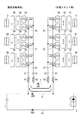
まずケーブルの脱着を簡単にする方法を提案する。接触抵抗の増大などの接触不良を減少させる最も有効な方法は接触する個所が無くなれば良いことであり、通信線を無くすことができれば接触不良が発生しないことは言うまでもない。通信線を無くす方法として周知されている既存の技術に直流重畳方式がある。図4はA地点の遠隔負荷17を駆動させるための直流の電力をB地点の遠隔負荷電源供給部18から供給している回路においてコイルおよびコンデンサのインピーダンスの性質を活用し直流回路に交流信号を重ね合わせる一般的な直流重畳方式の回路図である。
Hereinafter, the present invention will be described in detail based on embodiments.
<Corresponding to Issue 4>
First, we propose a method for simplifying cable insertion and removal. The most effective method for reducing contact failure such as increase in contact resistance is to eliminate the contact portion, and it goes without saying that contact failure does not occur if the communication line can be eliminated. There is a DC superposition method as an existing technique known as a method of eliminating a communication line. FIG. 4 is a circuit in which DC power for driving the
コイルのインピーダンスは式(1)で、コンデンサのインピーダンスは式(2)で求められるが、コイルのインピーダンスは周波数に比例し、コンデンサのインピーダンスは周波数に反比例することが解る。
コイルのインピーダンス ZL = jωL …(1)
コンデンサのインピーダンス ZC = 1/JωC …(2)
ω:2πf (πは円周率、fは周波数)、Jは虚数
例えば、図4のチョークコイルL3が1H(ヘンリー)のインダクタンスを持っていたとする。チョークコイルL3に1KHzの周波数を通過させようとした場合のチョークコイルL3のインピーダンスを式(1)に当てはめると式(3)のように大きな値となり交流送信器19から発せられる交流信号(制御信号及び情報信号に相当。以下、同じ。)が遠隔負荷電源供給部18の直流回路に侵入することを極力抑えることができるのである。
ZL3=ωL=2×3.14×(1×103)×1=6.28KΩ …(3)
Although the impedance of the coil is obtained by equation (1) and the impedance of the capacitor is obtained by equation (2), it can be seen that the impedance of the coil is proportional to the frequency and the impedance of the capacitor is inversely proportional to the frequency.
Coil impedance Z L = jωL (1)
Capacitor impedance Z C = 1 / JωC (2)
ω: 2πf (where π is a circular ratio, f is a frequency), J is an imaginary number For example, suppose that the choke coil L3 in FIG. 4 has an inductance of 1H (Henry). When the impedance of the choke coil L3 when passing the frequency of 1 KHz through the choke coil L3 is applied to the equation (1), the value becomes a large value as in the equation (3) and the AC signal (control signal) generated from the
Z L3 = ωL = 2 × 3.14 × (1 × 10 3 ) × 1 = 6.28 KΩ (3)
例えば、図4のカップリングコンデンサC3が1μF(マイクロファラド)の容量を持っていたとする。カップリングコンデンサC3に周波数1KHz(キロヘルツ)を通過させようとした場合のカップリングコンデンサC3のインピーダンスを式(2)に当てはめると式(4)のようにインピーダンスは比較的小さい値となり交流送信器19から発せられた交流信号は容易にカップリングコンデンサを通過して直流電源ライン21に侵入することができることになる。
ZC3=1/ωC=1/2×3.14×(1×103)×(1×10−6)=約159Ω …(4)
なおコンデンサの特性としては直流を通過させないことから、直流がコンデンサを通過し交流送信器19あるいは交流受信器20に影響を及ぼすことは無い。
For example, assume that the coupling capacitor C3 in FIG. 4 has a capacitance of 1 μF (microfarad). When the impedance of the coupling capacitor C3 when the frequency of 1 KHz (kilohertz) is allowed to pass through the coupling capacitor C3 is applied to the equation (2), the impedance becomes a relatively small value as in the equation (4), and the
Z C3 = 1 / ωC = 1 /2 × 3.14 × (1 × 10 3) × (1 × 10 -6) = about 159Ω ... (4)
Since the capacitor does not allow direct current to pass through, the direct current does not pass through the capacitor and does not affect the
こうしたことから図4において、B地点の交流送信器19から送出された交流信号は比較的インピーダンスが小さいカップリングコンデンサC3、C4、C1、C2を容易に通過しA地点の交流受信器20に到達することができるが、チョークコイルL3、L4、L1、L2のインピーダンスは比較的大きいことから交流送信器19が送出した交流信号はチュークコイルL3、L4、L1、L2に阻まれて遠隔負荷電源供給部18および遠隔負荷17に与える影響は極めて小さくなり直流回路に支障を与えない。
なお図4おいて、B地点の交流送信器をA地点に移し、A地点の交流受信器をB地点に移し送信器と受信器を入れ替えたとすると、A地点の交流送信器が送出する交流信号がB地点の交流受信器で受信できることは当然である。
For this reason, in FIG. 4, the AC signal sent from the
In FIG. 4, if the AC transmitter at point B is moved to point A, the AC receiver at point A is moved to point B, and the transmitter and receiver are replaced, the AC signal transmitted by the AC transmitter at point A is sent. Can be received by the AC receiver at point B.
一方、図5は、充電の直流部分のみを記した回路図である。図6は、図5で充電が行われる直流回路に交流信号を重畳させるべく図4と同様の考え方に基づいてカップリングコンデンサC3、C4、C1、C2とチョークコイルL3、L4、L1、L2を配備した仮想の回路図である。図6において充電スタンド側の交流送信器19から送出される交流信号は電気自動車側の交流受信器20まで伝送が可能であるかのように見えるが、現実には充電を行う回路において交流信号を直流回路に重畳することはできない。何故なら、チョークコイルはチョークコイルの使命である交流信号の通過を阻止しなければならないが、交流信号を阻止するには一定の大きさのインピーダンスにしなければならない。コイルのインピーダンスを大きくするにはコイルの巻き数を増やす必要がありコイルの巻き数を増やすことは直流抵抗が大きくなることと、電池のインピーダンスはゼロであることがその理由である。例えば図6において、チョークコイルL1〜L4のそれぞれの直流抵抗が1Ω(オーム)であったとするとチョークコイルL1〜L4の直流抵抗値の合計は1Ω×4個=4Ωとなるが、この回路に仮に100Aを流して急速充電を行おうとした場合チョークコイルL1〜L4の直流抵抗で消費される直流電力は式(5)となり某大な電力を消費する。
チョークコイルの消費電力 P=I2 R=1002×4=40K(VA)…(5)
VA:直流電力(交流のワット(W)に相当)
つまり電力供給源2から二次電池1に50KVAで充電しようとした場合、電力供給源2は充電経路に存在するチョークコイルL1〜L4が消費する無駄な電力である40VA分を上乗せした90KVAのエネルギーを捻出しなければないことになる。またチョークコイルによる無駄な電力消費を避けるためにチョークコイルL1〜L4を排除したと仮定すると、交流送信器19から送出された交流信号はカップリングコンデンサC3およびC4を経て充電ライン9〜10に侵入できるが、二次電池1のインピーダンスがゼロで(交流から見るとショート状態である)あるため交流信号は二次電池1で消滅してしまうのである。すなわち大電流が流れる充電回路にカップリングコンデンサやチョークコイルを配備しても充電回路に交流を重畳させ情報伝送を行うことは不可能なのである。
On the other hand, FIG. 5 is a circuit diagram showing only the DC part of charging. FIG. 6 shows coupling capacitors C3, C4, C1, C2 and choke coils L3, L4, L1, L2 based on the same concept as in FIG. 4 in order to superimpose an AC signal on the DC circuit to be charged in FIG. It is the deployed virtual circuit diagram. In FIG. 6, the AC signal sent from the
Power consumption of choke coil P = I 2 R = 100 2 × 4 = 40K (VA) (5)
VA: DC power (equivalent to AC wattage (W))
That is, when charging the
そこで、本実施形態では、図7に示す回路を提案する。通信を行うには、通常、図2および図3のように2本の通信ライン7および8が必要であるが、この2本の通信ラインのうち例えば通信ラインの片側である通信ライン7(第1通信ライン)とプラス側充電ライン9(第2通信ライン)を使い通信を行うものとした。つまり直流回路のうちのプラス側ラインにのみ交流信号を侵入させる、言わば、片線直流重畳方式である。しかしながら、通信の交流信号はプラス側充電ライン9にも流れているので、交流信号の接点数は通信ライン7が接触するコネクターCN1とプラス側充電ライン9のコネクターCN2の合計2か所であることに変わりは無く、通信信号の接触点の数が削減される訳ではない。
しかしながら、通信ラインを1/2に半減できるので接触部の極数を4極から3極に減らすことができる。
よって、解決すべき課題の一つである充電ケーブル接続時における故障を軽減させコンセントへの脱着を容易にすること(課題4)が可能となるのである。
なお、図8は、通信ライン7とマイナス側充電ライン10を使い通信を行うものであるが、図7と同じ機能となることは当然のことである。
Therefore, in this embodiment, the circuit shown in FIG. 7 is proposed. In order to perform communication, normally, two
However, since the communication line can be halved, the number of contact portions can be reduced from four to three.
Therefore, it is possible to reduce the failure at the time of connecting the charging cable, which is one of the problems to be solved, and to easily attach and detach the plug to the outlet (problem 4).
Note that FIG. 8 performs communication using the
<課題2対応>
次に、車内CAN通信を外部の充電スタンドと直接リンクさせない方法を説明する。
現在のインフラの一つに電話回線がある。電話回線の元々の考え方は、人間の声を電気信号に変換して遠方に届けようとする電線路であるが、この一対(2本の電線)の電話回線を利用してデジタル信号を遠方へ伝送する一般産業用の遠方監視制御装置(情報伝送装置と言う場合もある)が多々既存している。こうした情報伝送装置は主に、外部のコンピューターなどから多量のデータを取り込みまたは取り出すインターフェイス部と、規定された伝送プロトコルに従って送信するあるいは受信した信号に誤りが無いか検定するなどを行う符号化回路部と、デジタル信号をアナログ信号にするアナログモデムとで構成されている。なお、アナログモデムの任務は人間の耳で聞き取れる周波数(可聴周波数)である0.3〜3.4KHzの周波数の交流信号を使って遠方へ情報を伝送することである。こうした情報伝送方式は、符号化回路部とアナログモデムにより完璧に直流の微電圧回路はアイソレーションさせるのである。
図9は、信号を変調して送信する送信用アナログモデム23および受信信号を復調する受信用アナログモデム29と、符号化回路部(enc)35および36と、インターフェイス(IF)41と42を配備した情報伝送回路を示している。このような通信方式を活用して電気自動車内のCAN信号と充電スタンド間の通信を行うことで、電気自動車内のCAN通信を直接充電スタンドにリンクさせずアイソレーション(隔離)させることが可能となるのである。
<Corresponding to Issue 2>
Next, a method for not directly linking in-vehicle CAN communication with an external charging station will be described.
One of the current infrastructures is a telephone line. The original idea of a telephone line is an electric line that attempts to convert a human voice into an electrical signal and send it to a distant place. Using this pair of (two wires) telephone lines, a digital signal is sent to a far place. There are many existing remote monitoring and control devices (sometimes referred to as information transmission devices) for general industrial use. Such an information transmission device mainly includes an interface unit that captures or retrieves a large amount of data from an external computer, etc., and an encoding circuit unit that tests whether there is an error in a signal transmitted or received according to a specified transmission protocol. And an analog modem that converts a digital signal into an analog signal. The task of the analog modem is to transmit information to a distant place using an AC signal having a frequency of 0.3 to 3.4 KHz, which is a frequency (audible frequency) that can be heard by the human ear. In such an information transmission system, the DC micro voltage circuit is completely isolated by the encoding circuit unit and the analog modem.
FIG. 9 includes a
<課題1対応>
次に、以上の提案を踏まえた上で、最も重要な課題である急速充電時に電気自動車と充電スタンドを接続する際における通信ラインの接触点の抵抗が増大しても通信を可能にする方法を説明する。
図9において、充電スタンド側のマイコンボード4が伝えたいデジタル信号は、インターフェイス41および符号化回路部35を経て送信用アナログモデム23に伝達され、送信用アナログモデム23はこれをマイコンボード4が発したデジタル情報を可聴周波数に変調して受信用アナログモデム29に向けて送信する。
受信用アナログモデム29は送信用アナログモデム23からの可聴周波数の変調信号を捉えて復調し、復調された信号は符号化回路部36を経てインターフェイス42に渡される。インターフェイス42は、これをCAN信号に変換して車内の二次電池1の管理用である電子制御ユニット3へ伝達することができるのである。
このような構成を備えて電話回線で遠方まで情報を伝達する方法として一般産業用の遠方監視制御装置(情報伝送装置と言う場合もある)があることは前項で記したが、この一般産業用遠方監視制御装置には日本電機工業会が定めた規定(JEM−1318)がある。例えばJEM−1318の規定に準拠したアナログモデムで通信を行う場合、充電スタンドと電気自動車間の伝送路における抵抗値は約18KΩとなっても正常な通信が可能である。すなわちアナログモデムは電話回線(伝送路)を使って数Kmから数10Kmの遠方に正常に伝達させることを目的としており、電話回線(伝送路)を使って約10Kmの遠方に正常に伝達させることを目的としており、電話回線(伝送路)により送信された電気エネルギーが減衰することを想定して考えられたのがJEM−1318の規定である。JEM−1318に準拠したアナログモデムを数mと極めて短距離伝送に逆利用することにより充電スタンドと電気自動車間における通信ライン抵抗は約18KΩあっても全く問題なく通信が可能となるのである。
<Corresponding to Issue 1>
Next, based on the above proposals, a method that enables communication even when the resistance of the contact point of the communication line increases when connecting an electric vehicle and a charging stand during quick charging, which is the most important issue. explain.
In FIG. 9, a digital signal that the
The
As described in the previous section, there is a general industrial remote monitoring and control device (sometimes referred to as an information transmission device) as a method of transmitting information to a long distance via a telephone line with such a configuration. There is a regulation (JEM-1318) established by the Japan Electrical Manufacturers' Association in the remote monitoring control device. For example, when communication is performed with an analog modem that complies with the regulations of JEM-1318, normal communication is possible even if the resistance value in the transmission path between the charging station and the electric vehicle is about 18 KΩ. In other words, the purpose of analog modems is to transmit normally to a distance of several kilometers to several tens of kilometers using a telephone line (transmission path), and to transmit normally to a distance of about 10 km using a telephone line (transmission path). The purpose of JEM-1318 was to assume that electrical energy transmitted through a telephone line (transmission line) is attenuated. By reversely using an analog modem conforming to JEM-1318 for transmission over a very short distance of several meters, even if the communication line resistance between the charging station and the electric vehicle is about 18 KΩ, communication is possible without any problem.
ここでアナログモデム伝送理論の概要を説明する。
アナログモデムの伝送におけるインピーダンス系列は音声系の600Ωで行うものとされ、信号のレベルはデシベル(db)で表現され、信号レベルの基準は0(db)とされている。基準となっている0dbとは、インピーダンス600Ωの状態で1mWの電力値を絶対値として規定されていることから式(6)で表わされる。式(7)および式(8)は、式(6)からオームの法則で導いた0(db)における電圧値および電流値であり、600Ω系の0dbの電圧値は0.775Vであり電流値は1.2916mAであることが解る。
0dbとは、 P= V2/R = V2/600Ω = 1×10⁻³ W = 1mW … (6)
V0db = (1×10−3×0.6)1/2 = 0.775V … (7)
I0db = V/R = 0.775/600 = 1.2916mA … (8)
Here, the outline of analog modem transmission theory will be described.
The impedance series in the transmission of the analog modem is assumed to be 600 Ω of the audio system, the signal level is expressed in decibels (db), and the signal level reference is 0 (db). Reference 0db is expressed by equation (6) because the power value of 1 mW is defined as an absolute value in the state of impedance 600Ω. Equation (7) and Equation (8) are the voltage value and current value at 0 (db) derived from Ohm's law from Equation (6), and the voltage value of 0 db in the 600Ω system is 0.775 V and the current value Is found to be 1.2916 mA.
The 0db, P = V 2 / R =
V 0db = (1 × 10 −3 × 0.6) 1/2 = 0.775 V (7)
I 0db = V / R = 0.775 / 600 = 1.2916 mA (8)
さらにアナログモデムにおける伝送レベルの電力量を便宜的に計算する方法として式(9)が用いられている。
10・log10 A = X[db] …(9)
A:基準値に対する倍数 X:デシベル値
Furthermore, equation (9) is used as a method for conveniently calculating the transmission level power amount in the analog modem.
10 · log 10 A = X [db] (9)
A: Multiple to reference value X: Decibel value
一方、アナログモデムを有効活用している代表的な既存の情報伝送装置として遠方監視制御装置がある。遠方監視制御装置は電力会社の発変電所監視制御や国の河川ダム監視制御や自治体の水道事業などで広く使われているが、これらの遠方監視制御装置に関し日本電機工業会が規定した統一規格としてJEM−1318がある。JEM−1318のアナログモデムについて「信号伝送の項」には次のように規定されている。
送信レベル 0dbm/ch
受信レベル 0〜−20db/ch
回線断検出 標準着信よりも10〜15dbにて動作
ch : チャンネル
回線断検出 : モデムの受信能力があっても回線が切断されたとみなすべき値
すなわち、遠方監視制御装置に内蔵されているアナログモデムの送信出力が0(db)でありアナログモデムの受信器の受信レベルが−20dbで到達している通信伝送回線の場合、受信側における標準受信レベルである−20dbからさらに10〜15db下がった−30〜−35dbでも正常に受信しなければならないということを意味している。
ちなみに一般的な電話回線である0.4φの市内ケーブルは1Kmで約2dbの減衰が生じる。従って、仮に送信レベルを0dbとした遠方監視制御装置があったとする。これを0.4φのケーブルで伝送すると10Km先における遠方監視制御装置の受信レベルは約−20dbとなるのである。
−20dbとは、式(9)から0dbの1/100の電力値であることが解る。これを式(6)、式(7)及び式(8)に当てはめると、20Km先のアナログモデム受信器に到達する電力値は式(10)の0.01mWであり、電圧値は式(11)の0.0775Vであり、アナログモデム受信器に流れる電流は式(12)の0.12916mAとなる。
−20dbとは、 P = V2/600Ω = 0.01mW (10)
V−20db = 0.01×10−3 ×600 = 0.0775V (11)
I−20db = 0.0775V/600Ω= 0.129mA (12)
なお、正常に受信しなければならないとされている−30dbは、式(9)から1/1000の電力値なので、電力値は式(13)の0.001mWであり、電圧は式(14)の0.0245Vであり、電流は式(15)の0.0408mAとなる。
−30dbは、 P = V2/600Ω = 0.001mW (13)
V−30db = 0.001×10−3 ×600 = 0.0245V … (14)
I-30db = 0.0245V/600Ω = 0.0408mA … (15)
On the other hand, there is a remote monitoring control device as a typical existing information transmission device that effectively uses an analog modem. Remote monitoring and control devices are widely used in power company power station monitoring and control, national river dam monitoring and control, and municipal waterworks, etc. A unified standard established by the Japan Electrical Manufacturers' Association regarding these remote monitoring and control devices As JEM-1318. Regarding the analog modem of JEM-1318, “Signal transmission section” is defined as follows.
Transmission level 0dbm / ch
Line disconnection detection Operates at 10-15db from standard incoming calls
ch: Channel
Line disconnection detection: A value that should be regarded as a line disconnection even if the modem has reception capability. That is, the transmission output of the analog modem built in the remote monitoring control device is 0 (db), and the reception of the analog modem receiver is received. In the case of a communication transmission line that has reached a level of −20 db, it means that normal reception is required even at −30 to −35 db, which is 10 to 15 db lower than the standard reception level at −20 db on the receiving side. ing.
By the way, a 0.4φ local cable, which is a general telephone line, has an attenuation of about 2 db at 1 km. Accordingly, it is assumed that there is a remote monitoring and control apparatus that sets the transmission level to 0 db. If this is transmitted by a 0.4φ cable, the reception level of the remote
It can be understood from the equation (9) that −20 db is a power value of 1/100 of 0 db. When this is applied to Equation (6), Equation (7) and Equation (8), the power value reaching the
−20 db means P = V 2 /600Ω=0.01 mW (10)
V- 20db = 0.01 * 10 < -3 > * 600 = 0.0775V (11)
I- 20db = 0.0775V / 600Ω = 0.129mA (12)
Since -30db, which is supposed to be normally received, is a power value of 1/1000 from Equation (9), the power value is 0.001 mW of Equation (13), and the voltage is Equation (14). Of 0.0245 V, and the current is 0.0408 mA of equation (15).
−30 db is P = V 2 /600Ω=0.001 mW (13)
V -30db = 0.001 × 10 -3 × 600 = 0.0245V ... (14)
I -30db = 0.0245V / 600Ω = 0.0408mA ... (15)
図10は図9の回路に抵抗Rtを挿入し、送信用アナログモデム23から送出された交流の変調信号が受信用アナログモデム29に到着するレベルを減衰させようとした回路図である。仮に送信用アナログモデム23の送出レベルが0dbであり抵抗Rtにより受信用アナログモデム29の到着レベルが−20dbであったとすると、送信用アナログモデム23の電圧は式(7)から0.775であり受信用アナログモデム29の電圧は式(11)から0.0775Vであるから、通信回路にRtを挿入したことにより式(16)で示すように抵抗Rtで0.697Vの電圧が降下されることになる。よってオームの法則でRtの値を求めると式(17)となり、−20dbに減衰をさせているRtの抵抗値は5.4KΩであるこということになる。
Rtの電圧降下 VRt=0.775V−0.0775V=0.6975V … (16)
Rt = V/I = 0.6975/0.129×10−3= 5.4KΩ … (17)
FIG. 10 is a circuit diagram in which a resistor Rt is inserted into the circuit of FIG. 9 to attenuate the level at which the AC modulation signal transmitted from the transmitting
Rt voltage drop V Rt = 0.775V-0.0775V = 0.6975V (16)
Rt = V / I = 0.6975 / 0.129 × 10 −3 = 5.4 KΩ (17)
また、仮に送信用アナログモデム23が送出する変調信号のレベルが0dbであり抵抗Rtにより受信用アナログモデム29の到着レベルが−30dbであったとすると、送信用アナログモデム23の電圧は式(7)から0.775であり受信用アナログモデム29の電圧は式(14)から0.0245Vであるので、通信回路にRtを挿入したことにより式(18)で示すように抵抗Rtで0.7505Vの電圧が降下されることになる。よってオームの法則でRtの値を求めると式(19)となり、−30dbになるまで減衰させた時のRtの抵抗値は18.39KΩであるこということになる。
Rtの電圧降下 VRt=0.775V−0.0245V=0.7505V … (18)
Rt = V/I =0.7505/0.0408×10−3 =18.39KΩ … (19)
If the level of the modulation signal transmitted from the
Voltage drop of Rt V Rt = 0.775V-0.0245V = 0.7505V (18)
Rt = V / I = 0.7505 / 0.0408 × 10 −3 = 18.39 KΩ (19)
また、図10において何らかの理由で送信用アナログモデム23および受信用アナログモデム29の通信伝送路である通信ライン7とプラス側充電ライン9間にDC500V程度の充電電圧が印加されるような事故が発生しないとは言えない。こうしたことが発生すると送信用アナログモデム23および受信用アナログモデム29を損傷してしまい完全に通信不能となってしまう。
そこで、本実施形態では、図11のように直流を通過させないカップリングコンデンサC1〜C4を配備し、さらにアナログモデムの標準受信レベル−20dbまで減衰させた時のRtの値である5.4KΩの1/4の値1.35KΩの抵抗R1〜R4を分散配備し送信用アナログモデム23および受信用アナログモデム29をより安全に保護することとした。この状態においてアナログモデムの周波数が仮に1KHzとした場合、充分受信可能なレベル−30db時に相当するRtの値は18.39KΩであるから、18.39KΩからRtに相当するR1〜R4の合計値(1.35KΩ×4個=5.4KΩ)およびカップリングコンデンサC1〜C4のインピーダンス(159Ω×4個=636Ω)を差し引いた値である12.35KΩの抵抗が通信の伝送路に存在していても良いことになる。このことは、通信信号の接触点であるコネクターCN1とコネクターCN2の接触抵抗の合計値が12.35KΩになったとしても通信は十分可能であることを意味する。
つまり、充電スタンドからの充電時における従来の通信方式は直流微弱電圧回路であったために接触抵抗値(0.1Ω以下)の増大の有無が大きな障害となっていたが、JEM−1318に準じたアナログモデムを配備する方式にすることにより、0.1Ωの10万倍以上の12.35KΩが通信伝送路に存在しても何ら問題が無いのである。このことを言い換えれば、充電スタンドの保守点検においては通信ラインのコネクター部の交換を時折行う必要があるが、接触部の抵抗値の増大が時間に比例すると仮定するならば、コネクター部を交換する時期は実に約10万倍に延命させることが可能となるのである。
また、図11の片線直流重畳は通常の2線による通信回路と異なり充電用DC500Vが通信ライン7とプラス側充電ライン9の間、つまり通信回路に印加される故障の発生率はやや高い。したがって、送信用アナログモデム23と受信用アナログモデム29とカップリングコンデンサC1〜C4と、分散抵抗R1〜R4は、DC500V程度の電圧では損傷しない部品を選択して配備し、仮に故障した充電スタンドに充電ケーブルを接続しても電気自動車の通信機材に影響を与えないよう安全性の確保をすることが望まれる。
Further, in FIG. 10, there is an accident in which a charging voltage of about 500 V DC is applied between the
Therefore, in this embodiment, coupling capacitors C1 to C4 that do not allow direct current to pass as shown in FIG. 11 are provided, and the Rt value is 5.4 KΩ when the analog modem is attenuated to the standard reception level of −20 db. The resistors R1 to R4 having a 1/4 value of 1.35 KΩ are distributed to protect the transmitting
That is, since the conventional communication method at the time of charging from the charging station was a DC weak voltage circuit, the presence or absence of an increase in contact resistance value (0.1Ω or less) was a major obstacle, but conforming to JEM-1318 By adopting an analog modem system, there is no problem even if 12.35 KΩ, which is 100,000 times more than 0.1Ω, is present in the communication transmission line. In other words, in the maintenance and inspection of the charging station, it is sometimes necessary to replace the connector part of the communication line. However, if it is assumed that the increase in the resistance value of the contact part is proportional to time, the connector part is replaced. It is possible to extend the life by about 100,000 times.
In addition, unlike the normal two-wire communication circuit, the one-line DC superimposition in FIG. 11 has a slightly high failure rate when the charging DC 500V is applied between the
<課題3対応>
続いて多重通信の方法を説明する。例えば、JEM−1318においては「信号伝送の項」に次のことも記されている。
JEM−1318 「信号伝送」の項
伝送速度200ビット/秒において、次の条件によるものとのする。
使用周波数配列:800+400×(n−1)Hz (n=1〜6)
ここで言っている意味は、200ビット/秒(bps)の速度で伝送を行う場合においては、0.3〜3.4KHzの可聴周波数を以下に示すように6つのチャンネルに分割することとしているのである。つまり多重通信を行う場合には、まず800Hzの周波数で通信するチャンネルをチャンネル1(cH1)とし、400Hz上の周波数1200Hzを使って通信するチャンネルをチャンネル2(cH2)とし、順次400Hz離れた周波数で6つのャンネルを形成する。その上で、該当する周波数のみを通過させることができるバンドパスフィルターをアナログモデムに付加して該当する周波数のチャンネルを抽出して多重通信をすべきであると言っているのである。
200bpsのおけるチャンネル周波数
チャンネル(cH1) : 800Hz
チャンネル(cH2) : 1200Hz
チャンネル(cH3) : 1600Hz
チャンネル(cH4) : 2000Hz
チャンネル(cH5) : 2400Hz
チャンネル(cH6) : 2800Hz
<Corresponding to Issue 3>
Next, a multiplex communication method will be described. For example, in JEM-1318, the following is also described in “Signal transmission section”.
JEM-1318 “Signal transmission” At a transmission rate of 200 bits / second, the following conditions are assumed.
Frequency array used: 800 + 400 × (n−1) Hz (n = 1-6)
The meaning here is that when transmitting at a speed of 200 bits / second (bps), an audible frequency of 0.3 to 3.4 KHz is divided into six channels as shown below. It is. In other words, when performing multiplex communication, first, the channel that communicates at a frequency of 800 Hz is channel 1 (cH1), and the channel that communicates using a frequency of 1200 Hz above 400 Hz is channel 2 (cH2). Six channels are formed. In addition, it is said that a band pass filter capable of passing only the corresponding frequency should be added to the analog modem to extract the channel of the corresponding frequency and multiplex communication should be performed.
Channel frequency at 200 bps Channel (cH1): 800 Hz
Channel (cH2): 1200Hz
Channel (cH3): 1600Hz
Channel (cH4): 2000Hz
Channel (cH5): 2400Hz
Channel (cH6): 2800Hz
図12は、電気自動車と充電スタンドにおいて、JEM−1318に従い200bpsで多重通信を行った場合の図である。
例えば、チャンネル5(ch5)とチャンネル6(ch6)を使い、表1を用いて説明した急速充電に必要な情報を双方向通信で処理する。チャンネル1(ch1)とチャンネル2(ch2)を使い、例えば表2を用いて説明した車体の運用管理に必要な情報の双方向通信を行い、チャンネル3(ch3)とチャンネル4(ch4)を使い、表3を用いて説明した荷物管理に必要な情報の双方向通信を行うことができるのである。
なお、符号35〜40は各チャンネルの符号化回路部、符号41〜46は各チャンネルのインターフェイス、符号47〜50は各チャネルの急速受電用以外のコンピュータを示す。
FIG. 12 is a diagram when multiplex communication is performed at 200 bps in accordance with JEM-1318 in an electric vehicle and a charging station.
For example, channel 5 (ch5) and channel 6 (ch6) are used to process information necessary for the rapid charging described with reference to Table 1 by bidirectional communication. Using channel 1 (ch1) and channel 2 (ch2), for example, two-way communication of information necessary for vehicle operation management described with reference to Table 2 is performed, and channel 3 (ch3) and channel 4 (ch4) are used. The two-way communication of information necessary for the package management described with reference to Table 3 can be performed.
なお、電気自動車の急速充電においては充電電圧と充電電流の管理いわゆる「定電流・定電圧充電を厳密に管理するプロセス」は非常に重要であることは先に記した通りである。つまり、電池のセル電圧が一定になるまで定電流で充電し電池のセル電圧が一定になった瞬間に定電圧に切り替えることで充電による加熱事故を防止し、バッテリィの寿命を延ばすことに努めなければならないのである。この充電設定値の切り替えを行うにあたり200bps伝送速度の双方向通信では伝送遅れが心配される。しかしながら、仮にJEM−1318に準拠した方式に従い、200bpsの伝送速度で急速充電の管理制御を行ったとしてもても0.5秒以下で行えることから伝送遅れによる影響はほとんど無いが、さらに安全の期する必要があるならば充電制御信号に予測制御信号などの仕組みを加えたソフトウエア処理を実施することにより急速充電の管理の不安を除外することができる。
また、JEM−1318が規定する遠方監視制御装置は電話回線を使用して発電所やダムの監視および制御を行うことなどが目的であることから、様々な障害に耐える必要性がある。このことから多種多様に厳重な装備を施した強固で大型な装置であるが、電気自動車の急速充電用に特化するならば既存の遠方監視制御装置から排除しても良い部分(装備)は非常に多い。従って、仮に本質的部分のみJEM−1318に準じた、アイソレーションと符号化回路部とアナログモデムとを備えた双方向通信機を製作したとしても近年の電子機器製作技術からすれば、小型化は極めて容易であり、大量生産により安価で供給することも容易なことである。当然CAN通信を変換するインターフェイス部(IF)の製作も同様にして容易である。
It should be noted that as described above, in the rapid charging of an electric vehicle, the management of charging voltage and charging current, so-called “process for strictly managing constant current / constant voltage charging” is very important. In other words, charging with a constant current until the cell voltage of the battery becomes constant, and switching to the constant voltage at the moment when the cell voltage of the battery becomes constant prevents the heating accident due to charging and extends the life of the battery. It must be done. When switching the charge setting value, there is a concern about transmission delay in bidirectional communication at a transmission rate of 200 bps. However, even if quick charge management control is performed at a transmission rate of 200 bps in accordance with a method compliant with JEM-1318, it can be performed in 0.5 seconds or less, so there is almost no influence due to a transmission delay. If necessary, it is possible to eliminate the anxiety of rapid charge management by executing software processing in which a mechanism such as a predictive control signal is added to the charge control signal.
In addition, the remote monitoring and control apparatus defined by JEM-1318 is intended to monitor and control power plants and dams using a telephone line, and therefore needs to withstand various obstacles. For this reason, it is a strong and large-sized device with a variety of rigorous equipment, but if it is specialized for quick charging of electric vehicles, the parts (equipment) that can be excluded from existing remote monitoring and control devices Very many. Therefore, even if a bi-directional communication device including an isolation, an encoding circuit unit, and an analog modem according to JEM-1318 only in the essential part is manufactured, according to the recent electronic device manufacturing technology, downsizing is not possible. It is extremely easy to supply at low cost by mass production. Naturally, the production of an interface unit (IF) for converting CAN communication is also easy.
1 :二次電池、 2 :電力供給源、 3 :電子制御ユニット(ECU)、
4 :マイコンボード(CPU)、 5 :通信用ケーブル、 6 :充電用ケーブル、
7〜8 :通信ライン、9 :プラス側充電ライン、 10 :マイナス側充電ライン、
11〜12 :通信用コネクター、 13〜14 :充電用コネクター、 15〜16 :通信用および充電用の複合コネクター、 17 :遠隔負荷、 18 :遠隔負荷電源供給部、
19 :交流送信器、 20 :交流受信器、 21〜22 :直流電源ライン、
23〜28 :送信用アナログモデム、 29〜34 :受信用アナログンモデム、
35〜40 : 符号化回路部、 41〜46インターフェイス、
47〜50 :急速受電用以外のコンピュータ、
C1〜C4 :カップリングコンデンサ、 L1〜L4 :チョークコイル、
CN1〜CN3 :コネクター(接続部)、 Rt :抵抗、
R1〜R4 :分散抵抗
1: secondary battery, 2: power supply source, 3: electronic control unit (ECU),
4: microcomputer board (CPU), 5: communication cable, 6: charging cable,
7-8: Communication line, 9: Positive side charging line, 10: Negative side charging line,
11-12: Communication connector, 13-14: Charging connector, 15-16: Composite connector for communication and charging, 17: Remote load, 18: Remote load power supply unit,
19: AC transmitter, 20: AC receiver, 21-22: DC power line,
23 to 28: analog modem for transmission, 29 to 34: analog modem for reception,
35-40: Coding circuit part, 41-46 interface,
47-50: Computers other than for rapid power reception,
C1 to C4: coupling capacitors, L1 to L4: choke coils,
CN1 to CN3: connector (connection portion), Rt: resistance,
R1 to R4: Dispersion resistance
本発明は、充電の状態を制御する制御信号及び情報信号を充電スタンドに設けられる第1制御部と電気自動車に設けられる第2制御部との間で伝送しながら、充電スタンドに設けられる電力供給源から電気自動車に設けられる二次電池に直流電力を供給して二次電池を充電する方法に関するものである。
そして、直流電力の供給は、電力供給源と二次電池を繋ぐプラス側充電ラインとマイナス側充電ラインとを介して行われる。
また、制御信号及び情報信号の伝送は、第1制御部と第2制御部とを繋ぐ第1通信ラインと、プラス側充電ライン及びマイナス側充電ラインのいずれか一方を利用する第2通信ラインと、を介して行われる。
それにより、第1通信ラインと、第2通信ラインに利用されるプラス側充電ライン及びマイナス側充電ラインのいずれか一方と、第1制御部及び第2制御部とを含み、かつ電力供給源と二次電池とを含まない閉路が形成される。
The present invention provides a power supply provided in a charging stand while transmitting a control signal and an information signal for controlling a charging state between a first control unit provided in the charging stand and a second control unit provided in the electric vehicle. The present invention relates to a method for charging a secondary battery by supplying DC power from a source to a secondary battery provided in an electric vehicle.
The DC power is supplied through a positive charging line and a negative charging line connecting the power supply source and the secondary battery.
In addition, the transmission of the control signal and the information signal includes a first communication line connecting the first control unit and the second control unit, a second communication line using any one of the plus side charging line and the minus side charging line, , Done through.
Accordingly, the power supply source includes the first communication line, one of the positive charging line and the negative charging line used for the second communication line, the first control unit and the second control unit, and A closed circuit that does not include the secondary battery is formed.
Claims (5)
前記直流電力の供給は、
前記電力供給源と前記二次電池を繋ぐプラス側充電ラインとマイナス側充電ラインとを介して行われ、
前記制御信号及び前記情報信号の伝送は、
前記第1制御部と前記第2制御部とを繋ぐ第1通信ラインと、前記プラス側充電ライン及び前記マイナス側充電ラインのいずれか一方を利用する第2通信ラインと、を介して行われる、
ことを特徴とする充電方法。 While transmitting the control signal and the information signal for controlling the state of charging between the first control unit provided in the charging stand and the second control unit provided in the electric vehicle, the power supply source provided in the charging stand A method of charging the secondary battery by supplying direct current power to a secondary battery provided in an electric vehicle,
The supply of DC power is
It is performed via a positive charging line and a negative charging line connecting the power supply source and the secondary battery,
Transmission of the control signal and the information signal is as follows:
A first communication line connecting the first control unit and the second control unit, and a second communication line using one of the positive side charging line and the negative side charging line.
A charging method characterized by that.
前記第2制御部は第2アナログモデムを備え、
前記制御信号及び前記情報信号は、前記第1アナログモデムと前記第2アナログモデムとを介して、前記第1制御部と前記第2制御部との間で相互に伝送される、
ことを特徴とする請求項1に記載の充電方法。 The first control unit includes a first analog modem;
The second control unit includes a second analog modem;
The control signal and the information signal are mutually transmitted between the first control unit and the second control unit via the first analog modem and the second analog modem.
The charging method according to claim 1.
前記第2制御部は第2アナログモデム及び第2符号化回路部を備え、
前記制御信号及び前記情報信号は、前記第1アナログモデム及び前記第1符号化回路部と、前記第2アナログモデム及び前記第2符号化回路部とを介して、前記第1制御部と前記第2制御部との間で相互に伝送される、
請求項1に記載の充電方法。 The first control unit includes a first analog modem and a first encoding circuit unit,
The second control unit includes a second analog modem and a second encoding circuit unit,
The control signal and the information signal are transmitted to the first control unit and the first encoding circuit unit via the first analog modem and the first encoding circuit unit, and the second analog modem and the second encoding circuit unit, respectively. Are transmitted between two control units,
The charging method according to claim 1.
請求項1〜3のいずれか一項に記載の充電方法。 A resistor and a coupling capacitor are provided in the first communication line and the second communication line.
The charging method according to any one of claims 1 to 3.
請求項1〜4のいずれか一項に記載の充電方法。 Transmission of the control signal and the information signal between the first control unit and the second control unit is performed by multiplex communication by frequency division.
The charging method according to any one of claims 1 to 4.
Priority Applications (1)
| Application Number | Priority Date | Filing Date | Title |
|---|---|---|---|
| JP2010269791A JP4803849B1 (en) | 2010-12-02 | 2010-12-02 | How to charge an electric vehicle |
Applications Claiming Priority (1)
| Application Number | Priority Date | Filing Date | Title |
|---|---|---|---|
| JP2010269791A JP4803849B1 (en) | 2010-12-02 | 2010-12-02 | How to charge an electric vehicle |
Publications (2)
| Publication Number | Publication Date |
|---|---|
| JP4803849B1 JP4803849B1 (en) | 2011-10-26 |
| JP2012120383A true JP2012120383A (en) | 2012-06-21 |
Family
ID=44946863
Family Applications (1)
| Application Number | Title | Priority Date | Filing Date |
|---|---|---|---|
| JP2010269791A Expired - Fee Related JP4803849B1 (en) | 2010-12-02 | 2010-12-02 | How to charge an electric vehicle |
Country Status (1)
| Country | Link |
|---|---|
| JP (1) | JP4803849B1 (en) |
Cited By (2)
| Publication number | Priority date | Publication date | Assignee | Title |
|---|---|---|---|---|
| JP2018506934A (en) * | 2014-12-29 | 2018-03-08 | フロニウス・インテルナツィオナール・ゲゼルシャフト・ミット・ベシュレンクテル・ハフツングFronius International Gmbh | Power transmission system |
| JP2018093608A (en) * | 2016-12-01 | 2018-06-14 | 日産自動車株式会社 | Charging system for electric vehicle and on-vehicle charging unit |
Families Citing this family (3)
| Publication number | Priority date | Publication date | Assignee | Title |
|---|---|---|---|---|
| JP5888005B2 (en) * | 2012-02-29 | 2016-03-16 | 住友電気工業株式会社 | Power supply apparatus and communication method |
| JP5903993B2 (en) * | 2012-04-03 | 2016-04-13 | 住友電気工業株式会社 | Communications system |
| CN116914896B (en) * | 2023-09-13 | 2024-01-05 | 深圳市智安新能源科技有限公司 | Method and system for communication between battery and charger |
Family Cites Families (7)
| Publication number | Priority date | Publication date | Assignee | Title |
|---|---|---|---|---|
| JP2879285B2 (en) * | 1993-02-19 | 1999-04-05 | 富士通電装株式会社 | Communication control method for electric vehicles |
| JPH06245325A (en) * | 1993-02-22 | 1994-09-02 | Fujitsu Denso Ltd | Communication control system for electric automobile |
| JPH06343205A (en) * | 1993-06-01 | 1994-12-13 | Nissan Motor Co Ltd | Electric car battery charger |
| JPH07240705A (en) * | 1994-02-28 | 1995-09-12 | Clarion Co Ltd | Electric automobile charging system |
| DE10142409A1 (en) * | 2001-08-31 | 2003-04-17 | Bosch Gmbh Robert | Supply line structure for the transmission of information between motor vehicle components |
| JP5344895B2 (en) * | 2008-12-10 | 2013-11-20 | 矢崎総業株式会社 | Charge monitoring device |
| JP5369833B2 (en) * | 2009-03-31 | 2013-12-18 | 東京電力株式会社 | Electric vehicle charger and ground fault detection method |
-
2010
- 2010-12-02 JP JP2010269791A patent/JP4803849B1/en not_active Expired - Fee Related
Cited By (2)
| Publication number | Priority date | Publication date | Assignee | Title |
|---|---|---|---|---|
| JP2018506934A (en) * | 2014-12-29 | 2018-03-08 | フロニウス・インテルナツィオナール・ゲゼルシャフト・ミット・ベシュレンクテル・ハフツングFronius International Gmbh | Power transmission system |
| JP2018093608A (en) * | 2016-12-01 | 2018-06-14 | 日産自動車株式会社 | Charging system for electric vehicle and on-vehicle charging unit |
Also Published As
| Publication number | Publication date |
|---|---|
| JP4803849B1 (en) | 2011-10-26 |
Similar Documents
| Publication | Publication Date | Title |
|---|---|---|
| JP4803849B1 (en) | How to charge an electric vehicle | |
| US20120112694A1 (en) | Method and Arrangement for Data Communication Between A Service Provider and A Vehicle | |
| US9511676B2 (en) | Portable EV energy transfer apparatus and method | |
| EP2525466B1 (en) | Electric power supply device and vehicle charge system | |
| EP2405555A1 (en) | Power supply device | |
| KR101338003B1 (en) | Device of power line communication for electric vehicle charging and system for it | |
| US11267360B2 (en) | Modular charging systems for vehicles | |
| EP2692570B1 (en) | In-vehicle charging device | |
| CA2959028C (en) | Self-powered wireless fuse switch | |
| EP2530810B1 (en) | Vehicle charging device and vehicle charging system using same | |
| WO2011102068A1 (en) | Charge control apparatus and vehicle charge system | |
| JP2014117975A (en) | In-vehicle communication device and communication system | |
| CN103636139B (en) | Communication system and communicator | |
| US20150280432A1 (en) | Home charging and power backup unit | |
| GB2506185A (en) | Fault detection system for electric vehicle charging | |
| WO2013150820A1 (en) | Communication device and communication system | |
| JP2012135111A (en) | Vehicle charge cable management system | |
| KR20140123622A (en) | System and method for charging electric vehicle | |
| JP2013187850A (en) | Connection device and communication system | |
| WO2014169927A1 (en) | Method and arrangement for error detection during charging of an energy storage system | |
| JP5353082B2 (en) | Vehicle power supply control device | |
| CN103633672B (en) | The power supply protection device of in-vehicle wireless device and method of supplying power to | |
| KR101304426B1 (en) | Ship system using Power Line Communication | |
| CN112092655B (en) | Charging station communication system, method and charging station | |
| CN102568179A (en) | Two-channel wireless transmission power monitoring system and monitoring method thereof |
Legal Events
| Date | Code | Title | Description |
|---|---|---|---|
| TRDD | Decision of grant or rejection written | ||
| A01 | Written decision to grant a patent or to grant a registration (utility model) |
Free format text: JAPANESE INTERMEDIATE CODE: A01 Effective date: 20110803 |
|
| A01 | Written decision to grant a patent or to grant a registration (utility model) |
Free format text: JAPANESE INTERMEDIATE CODE: A01 |
|
| A61 | First payment of annual fees (during grant procedure) |
Free format text: JAPANESE INTERMEDIATE CODE: A61 Effective date: 20110808 |
|
| R150 | Certificate of patent or registration of utility model |
Free format text: JAPANESE INTERMEDIATE CODE: R150 |
|
| FPAY | Renewal fee payment (event date is renewal date of database) |
Free format text: PAYMENT UNTIL: 20140819 Year of fee payment: 3 |
|
| LAPS | Cancellation because of no payment of annual fees |