JP2012135111A - Vehicle charge cable management system - Google Patents
Vehicle charge cable management system Download PDFInfo
- Publication number
- JP2012135111A JP2012135111A JP2010284687A JP2010284687A JP2012135111A JP 2012135111 A JP2012135111 A JP 2012135111A JP 2010284687 A JP2010284687 A JP 2010284687A JP 2010284687 A JP2010284687 A JP 2010284687A JP 2012135111 A JP2012135111 A JP 2012135111A
- Authority
- JP
- Japan
- Prior art keywords
- vehicle
- charging
- cable
- charging cable
- power line
- Prior art date
- Legal status (The legal status is an assumption and is not a legal conclusion. Google has not performed a legal analysis and makes no representation as to the accuracy of the status listed.)
- Pending
Links
Images


Classifications
-
- B—PERFORMING OPERATIONS; TRANSPORTING
- B60—VEHICLES IN GENERAL
- B60L—PROPULSION OF ELECTRICALLY-PROPELLED VEHICLES; SUPPLYING ELECTRIC POWER FOR AUXILIARY EQUIPMENT OF ELECTRICALLY-PROPELLED VEHICLES; ELECTRODYNAMIC BRAKE SYSTEMS FOR VEHICLES IN GENERAL; MAGNETIC SUSPENSION OR LEVITATION FOR VEHICLES; MONITORING OPERATING VARIABLES OF ELECTRICALLY-PROPELLED VEHICLES; ELECTRIC SAFETY DEVICES FOR ELECTRICALLY-PROPELLED VEHICLES
- B60L3/00—Electric devices on electrically-propelled vehicles for safety purposes; Monitoring operating variables, e.g. speed, deceleration or energy consumption
- B60L3/0023—Detecting, eliminating, remedying or compensating for drive train abnormalities, e.g. failures within the drive train
- B60L3/0069—Detecting, eliminating, remedying or compensating for drive train abnormalities, e.g. failures within the drive train relating to the isolation, e.g. ground fault or leak current
-
- B—PERFORMING OPERATIONS; TRANSPORTING
- B60—VEHICLES IN GENERAL
- B60L—PROPULSION OF ELECTRICALLY-PROPELLED VEHICLES; SUPPLYING ELECTRIC POWER FOR AUXILIARY EQUIPMENT OF ELECTRICALLY-PROPELLED VEHICLES; ELECTRODYNAMIC BRAKE SYSTEMS FOR VEHICLES IN GENERAL; MAGNETIC SUSPENSION OR LEVITATION FOR VEHICLES; MONITORING OPERATING VARIABLES OF ELECTRICALLY-PROPELLED VEHICLES; ELECTRIC SAFETY DEVICES FOR ELECTRICALLY-PROPELLED VEHICLES
- B60L3/00—Electric devices on electrically-propelled vehicles for safety purposes; Monitoring operating variables, e.g. speed, deceleration or energy consumption
- B60L3/04—Cutting off the power supply under fault conditions
-
- B—PERFORMING OPERATIONS; TRANSPORTING
- B60—VEHICLES IN GENERAL
- B60L—PROPULSION OF ELECTRICALLY-PROPELLED VEHICLES; SUPPLYING ELECTRIC POWER FOR AUXILIARY EQUIPMENT OF ELECTRICALLY-PROPELLED VEHICLES; ELECTRODYNAMIC BRAKE SYSTEMS FOR VEHICLES IN GENERAL; MAGNETIC SUSPENSION OR LEVITATION FOR VEHICLES; MONITORING OPERATING VARIABLES OF ELECTRICALLY-PROPELLED VEHICLES; ELECTRIC SAFETY DEVICES FOR ELECTRICALLY-PROPELLED VEHICLES
- B60L50/00—Electric propulsion with power supplied within the vehicle
- B60L50/10—Electric propulsion with power supplied within the vehicle using propulsion power supplied by engine-driven generators, e.g. generators driven by combustion engines
- B60L50/16—Electric propulsion with power supplied within the vehicle using propulsion power supplied by engine-driven generators, e.g. generators driven by combustion engines with provision for separate direct mechanical propulsion
-
- B—PERFORMING OPERATIONS; TRANSPORTING
- B60—VEHICLES IN GENERAL
- B60L—PROPULSION OF ELECTRICALLY-PROPELLED VEHICLES; SUPPLYING ELECTRIC POWER FOR AUXILIARY EQUIPMENT OF ELECTRICALLY-PROPELLED VEHICLES; ELECTRODYNAMIC BRAKE SYSTEMS FOR VEHICLES IN GENERAL; MAGNETIC SUSPENSION OR LEVITATION FOR VEHICLES; MONITORING OPERATING VARIABLES OF ELECTRICALLY-PROPELLED VEHICLES; ELECTRIC SAFETY DEVICES FOR ELECTRICALLY-PROPELLED VEHICLES
- B60L53/00—Methods of charging batteries, specially adapted for electric vehicles; Charging stations or on-board charging equipment therefor; Exchange of energy storage elements in electric vehicles
- B60L53/10—Methods of charging batteries, specially adapted for electric vehicles; Charging stations or on-board charging equipment therefor; Exchange of energy storage elements in electric vehicles characterised by the energy transfer between the charging station and the vehicle
- B60L53/14—Conductive energy transfer
- B60L53/16—Connectors, e.g. plugs or sockets, specially adapted for charging electric vehicles
-
- B—PERFORMING OPERATIONS; TRANSPORTING
- B60—VEHICLES IN GENERAL
- B60L—PROPULSION OF ELECTRICALLY-PROPELLED VEHICLES; SUPPLYING ELECTRIC POWER FOR AUXILIARY EQUIPMENT OF ELECTRICALLY-PROPELLED VEHICLES; ELECTRODYNAMIC BRAKE SYSTEMS FOR VEHICLES IN GENERAL; MAGNETIC SUSPENSION OR LEVITATION FOR VEHICLES; MONITORING OPERATING VARIABLES OF ELECTRICALLY-PROPELLED VEHICLES; ELECTRIC SAFETY DEVICES FOR ELECTRICALLY-PROPELLED VEHICLES
- B60L53/00—Methods of charging batteries, specially adapted for electric vehicles; Charging stations or on-board charging equipment therefor; Exchange of energy storage elements in electric vehicles
- B60L53/10—Methods of charging batteries, specially adapted for electric vehicles; Charging stations or on-board charging equipment therefor; Exchange of energy storage elements in electric vehicles characterised by the energy transfer between the charging station and the vehicle
- B60L53/14—Conductive energy transfer
- B60L53/18—Cables specially adapted for charging electric vehicles
-
- B—PERFORMING OPERATIONS; TRANSPORTING
- B60—VEHICLES IN GENERAL
- B60L—PROPULSION OF ELECTRICALLY-PROPELLED VEHICLES; SUPPLYING ELECTRIC POWER FOR AUXILIARY EQUIPMENT OF ELECTRICALLY-PROPELLED VEHICLES; ELECTRODYNAMIC BRAKE SYSTEMS FOR VEHICLES IN GENERAL; MAGNETIC SUSPENSION OR LEVITATION FOR VEHICLES; MONITORING OPERATING VARIABLES OF ELECTRICALLY-PROPELLED VEHICLES; ELECTRIC SAFETY DEVICES FOR ELECTRICALLY-PROPELLED VEHICLES
- B60L53/00—Methods of charging batteries, specially adapted for electric vehicles; Charging stations or on-board charging equipment therefor; Exchange of energy storage elements in electric vehicles
- B60L53/30—Constructional details of charging stations
- B60L53/305—Communication interfaces
-
- B—PERFORMING OPERATIONS; TRANSPORTING
- B60—VEHICLES IN GENERAL
- B60L—PROPULSION OF ELECTRICALLY-PROPELLED VEHICLES; SUPPLYING ELECTRIC POWER FOR AUXILIARY EQUIPMENT OF ELECTRICALLY-PROPELLED VEHICLES; ELECTRODYNAMIC BRAKE SYSTEMS FOR VEHICLES IN GENERAL; MAGNETIC SUSPENSION OR LEVITATION FOR VEHICLES; MONITORING OPERATING VARIABLES OF ELECTRICALLY-PROPELLED VEHICLES; ELECTRIC SAFETY DEVICES FOR ELECTRICALLY-PROPELLED VEHICLES
- B60L53/00—Methods of charging batteries, specially adapted for electric vehicles; Charging stations or on-board charging equipment therefor; Exchange of energy storage elements in electric vehicles
- B60L53/60—Monitoring or controlling charging stations
- B60L53/65—Monitoring or controlling charging stations involving identification of vehicles or their battery types
-
- B—PERFORMING OPERATIONS; TRANSPORTING
- B60—VEHICLES IN GENERAL
- B60L—PROPULSION OF ELECTRICALLY-PROPELLED VEHICLES; SUPPLYING ELECTRIC POWER FOR AUXILIARY EQUIPMENT OF ELECTRICALLY-PROPELLED VEHICLES; ELECTRODYNAMIC BRAKE SYSTEMS FOR VEHICLES IN GENERAL; MAGNETIC SUSPENSION OR LEVITATION FOR VEHICLES; MONITORING OPERATING VARIABLES OF ELECTRICALLY-PROPELLED VEHICLES; ELECTRIC SAFETY DEVICES FOR ELECTRICALLY-PROPELLED VEHICLES
- B60L2250/00—Driver interactions
- B60L2250/10—Driver interactions by alarm
-
- B—PERFORMING OPERATIONS; TRANSPORTING
- B60—VEHICLES IN GENERAL
- B60L—PROPULSION OF ELECTRICALLY-PROPELLED VEHICLES; SUPPLYING ELECTRIC POWER FOR AUXILIARY EQUIPMENT OF ELECTRICALLY-PROPELLED VEHICLES; ELECTRODYNAMIC BRAKE SYSTEMS FOR VEHICLES IN GENERAL; MAGNETIC SUSPENSION OR LEVITATION FOR VEHICLES; MONITORING OPERATING VARIABLES OF ELECTRICALLY-PROPELLED VEHICLES; ELECTRIC SAFETY DEVICES FOR ELECTRICALLY-PROPELLED VEHICLES
- B60L2270/00—Problem solutions or means not otherwise provided for
- B60L2270/30—Preventing theft during charging
- B60L2270/34—Preventing theft during charging of parts
-
- Y—GENERAL TAGGING OF NEW TECHNOLOGICAL DEVELOPMENTS; GENERAL TAGGING OF CROSS-SECTIONAL TECHNOLOGIES SPANNING OVER SEVERAL SECTIONS OF THE IPC; TECHNICAL SUBJECTS COVERED BY FORMER USPC CROSS-REFERENCE ART COLLECTIONS [XRACs] AND DIGESTS
- Y02—TECHNOLOGIES OR APPLICATIONS FOR MITIGATION OR ADAPTATION AGAINST CLIMATE CHANGE
- Y02T—CLIMATE CHANGE MITIGATION TECHNOLOGIES RELATED TO TRANSPORTATION
- Y02T10/00—Road transport of goods or passengers
- Y02T10/60—Other road transportation technologies with climate change mitigation effect
- Y02T10/70—Energy storage systems for electromobility, e.g. batteries
-
- Y—GENERAL TAGGING OF NEW TECHNOLOGICAL DEVELOPMENTS; GENERAL TAGGING OF CROSS-SECTIONAL TECHNOLOGIES SPANNING OVER SEVERAL SECTIONS OF THE IPC; TECHNICAL SUBJECTS COVERED BY FORMER USPC CROSS-REFERENCE ART COLLECTIONS [XRACs] AND DIGESTS
- Y02—TECHNOLOGIES OR APPLICATIONS FOR MITIGATION OR ADAPTATION AGAINST CLIMATE CHANGE
- Y02T—CLIMATE CHANGE MITIGATION TECHNOLOGIES RELATED TO TRANSPORTATION
- Y02T10/00—Road transport of goods or passengers
- Y02T10/60—Other road transportation technologies with climate change mitigation effect
- Y02T10/7072—Electromobility specific charging systems or methods for batteries, ultracapacitors, supercapacitors or double-layer capacitors
-
- Y—GENERAL TAGGING OF NEW TECHNOLOGICAL DEVELOPMENTS; GENERAL TAGGING OF CROSS-SECTIONAL TECHNOLOGIES SPANNING OVER SEVERAL SECTIONS OF THE IPC; TECHNICAL SUBJECTS COVERED BY FORMER USPC CROSS-REFERENCE ART COLLECTIONS [XRACs] AND DIGESTS
- Y02—TECHNOLOGIES OR APPLICATIONS FOR MITIGATION OR ADAPTATION AGAINST CLIMATE CHANGE
- Y02T—CLIMATE CHANGE MITIGATION TECHNOLOGIES RELATED TO TRANSPORTATION
- Y02T90/00—Enabling technologies or technologies with a potential or indirect contribution to GHG emissions mitigation
- Y02T90/10—Technologies relating to charging of electric vehicles
- Y02T90/12—Electric charging stations
-
- Y—GENERAL TAGGING OF NEW TECHNOLOGICAL DEVELOPMENTS; GENERAL TAGGING OF CROSS-SECTIONAL TECHNOLOGIES SPANNING OVER SEVERAL SECTIONS OF THE IPC; TECHNICAL SUBJECTS COVERED BY FORMER USPC CROSS-REFERENCE ART COLLECTIONS [XRACs] AND DIGESTS
- Y02—TECHNOLOGIES OR APPLICATIONS FOR MITIGATION OR ADAPTATION AGAINST CLIMATE CHANGE
- Y02T—CLIMATE CHANGE MITIGATION TECHNOLOGIES RELATED TO TRANSPORTATION
- Y02T90/00—Enabling technologies or technologies with a potential or indirect contribution to GHG emissions mitigation
- Y02T90/10—Technologies relating to charging of electric vehicles
- Y02T90/14—Plug-in electric vehicles
-
- Y—GENERAL TAGGING OF NEW TECHNOLOGICAL DEVELOPMENTS; GENERAL TAGGING OF CROSS-SECTIONAL TECHNOLOGIES SPANNING OVER SEVERAL SECTIONS OF THE IPC; TECHNICAL SUBJECTS COVERED BY FORMER USPC CROSS-REFERENCE ART COLLECTIONS [XRACs] AND DIGESTS
- Y02—TECHNOLOGIES OR APPLICATIONS FOR MITIGATION OR ADAPTATION AGAINST CLIMATE CHANGE
- Y02T—CLIMATE CHANGE MITIGATION TECHNOLOGIES RELATED TO TRANSPORTATION
- Y02T90/00—Enabling technologies or technologies with a potential or indirect contribution to GHG emissions mitigation
- Y02T90/10—Technologies relating to charging of electric vehicles
- Y02T90/16—Information or communication technologies improving the operation of electric vehicles
- Y02T90/167—Systems integrating technologies related to power network operation and communication or information technologies for supporting the interoperability of electric or hybrid vehicles, i.e. smartgrids as interface for battery charging of electric vehicles [EV] or hybrid vehicles [HEV]
-
- Y—GENERAL TAGGING OF NEW TECHNOLOGICAL DEVELOPMENTS; GENERAL TAGGING OF CROSS-SECTIONAL TECHNOLOGIES SPANNING OVER SEVERAL SECTIONS OF THE IPC; TECHNICAL SUBJECTS COVERED BY FORMER USPC CROSS-REFERENCE ART COLLECTIONS [XRACs] AND DIGESTS
- Y04—INFORMATION OR COMMUNICATION TECHNOLOGIES HAVING AN IMPACT ON OTHER TECHNOLOGY AREAS
- Y04S—SYSTEMS INTEGRATING TECHNOLOGIES RELATED TO POWER NETWORK OPERATION, COMMUNICATION OR INFORMATION TECHNOLOGIES FOR IMPROVING THE ELECTRICAL POWER GENERATION, TRANSMISSION, DISTRIBUTION, MANAGEMENT OR USAGE, i.e. SMART GRIDS
- Y04S30/00—Systems supporting specific end-user applications in the sector of transportation
- Y04S30/10—Systems supporting the interoperability of electric or hybrid vehicles
- Y04S30/14—Details associated with the interoperability, e.g. vehicle recognition, authentication, identification or billing
Landscapes
- Engineering & Computer Science (AREA)
- Power Engineering (AREA)
- Transportation (AREA)
- Mechanical Engineering (AREA)
- Life Sciences & Earth Sciences (AREA)
- Sustainable Development (AREA)
- Sustainable Energy (AREA)
- Charge And Discharge Circuits For Batteries Or The Like (AREA)
- Secondary Cells (AREA)
- Electric Propulsion And Braking For Vehicles (AREA)
Abstract
Description
本発明は、電気自動車(以下、車両ともいう)に充電する車両用充電ケーブルの充電回数(使用回数または耐用回数ともよばれる)を管理し、ユーザに通知する車両用充電ケーブル管理システムに関する。 The present invention relates to a vehicle charging cable management system that manages the number of times of charging (also referred to as the number of times of use or durability) of a vehicle charging cable for charging an electric vehicle (hereinafter also referred to as a vehicle) and notifies the user.
従来、特許文献1に記載の車両用充電ケーブルにおける、充電回数判定装置が公知である。この充電回数判定装置は、車両用充電ケーブルに装着されている充電回数判定装置と、充電回数表示装置と、充電の制限を指示するように構成された指令出力部を含む充電回路遮断制御装置(以下、CCIDBOXともいう)を有する。
2. Description of the Related Art Conventionally, a charging number determination device in a vehicle charging cable described in
そして、充電回数を判定し、CCIDBOX内にて充電回数を管理するものである。また、充電回数が所定の基準値を超過していた場合、CCIDBOX内の指令出力部により、充電規制が行われる。この充電規制とは、CPLT(パイロット信号)の発振停止、またはCCIDBOX内のCCID(Charging Circuit Interrupt Device)リレーの遮断によって、充電を停止させる事である。 Then, the number of times of charging is determined, and the number of times of charging is managed in the CCIDBOX. Further, when the number of times of charging exceeds a predetermined reference value, charging regulation is performed by the command output unit in the CCIDBOX. The charging regulation is to stop charging by stopping oscillation of CPLT (pilot signal) or cutting off a CCID (Charging Circuit Interrupt Device) relay in the CCIDBOX.
特許文献1の技術では、充電回数をCCIDBOX内でカウントしている為、CCIDBOXが故障した場合、車両用充電ケーブルの充電回数がわからなくなるといった問題がある。
In the technique of
本発明は、このような従来の技術に存在する問題点に着目して成されたものであり、その目的は、充電回路遮断制御装置(CCIDBOX)が故障した場合においても、車両用充電ケーブルの充電回数(使用回数)が判明する車両用充電ケーブル管理システムを提供することにある。 The present invention has been made paying attention to such problems existing in the prior art, and the object of the present invention is to provide a vehicle charging cable even when the charging circuit cutoff control device (CCIDBOX) fails. The object is to provide a vehicle charging cable management system in which the number of times of charging (number of times of use) is known.
従来技術として列挙された特許文献の記載内容は、この明細書に記載された技術的要素の説明として、参照によって導入ないし援用することができる。 Descriptions of patent documents listed as prior art can be introduced or incorporated by reference as explanations of technical elements described in this specification.
本発明は上記目的を達成するために、下記の技術的手段を採用する。すなわち、請求項1に記載の発明では、車両に住居内からの電力で充電する車両用充電ケーブルの充電回数を管理し、ユーザに通知する車両用充電ケーブル管理システムであって、車両用充電ケーブルに装着され、車両用充電ケーブルを個別に特定するための車両用充電ケーブル特定情報を記憶する充電回路遮断制御装置と、充電回路遮断制御装置内に搭載されたケーブル内電力線通信用モジュールと、車両用充電ケーブルの外部に設けられた装置であって、車両用充電ケーブル特定情報を、ケーブル内電力線通信用モジュールを用いた電力線通信により、充電する毎に取得し、車両用充電ケーブルにおける充電回数を管理する管理装置とを有することを特徴としている。 In order to achieve the above object, the present invention employs the following technical means. That is, according to the first aspect of the present invention, there is provided a vehicle charging cable management system that manages the number of times of charging of a vehicle charging cable for charging the vehicle with electric power from a residence and notifies the user of the charging cable. , A charging circuit cutoff control device for storing vehicle charging cable specifying information for individually specifying a vehicle charging cable, an in-cable power line communication module mounted in the charging circuit cutoff control device, and a vehicle This is a device provided outside the charging cable for the vehicle, and the vehicle charging cable specific information is acquired every time charging is performed by power line communication using the power line communication module in the cable, and the number of times of charging in the vehicle charging cable It has the management apparatus to manage.
この発明によれば、ケーブル内電力線通信用モジュールを用いて、車両用充電ケーブルの充電回数を外部の管理装置で管理する為、充電回路遮断制御装置(CCIDBOX)が故障しても、車両用充電ケーブルを使用した充電回数が失われることがなく、過度に使用された車両用充電ケーブルの使用に基づく故障を未然に防止することができる。 According to the present invention, since the number of times of charging of the vehicle charging cable is managed by the external management device using the in-cable power line communication module, even if the charging circuit cutoff control device (CCIDBOX) breaks down, the vehicle charging is performed. The number of times of charging using the cable is not lost, and a failure due to the use of an excessively used vehicle charging cable can be prevented in advance.
請求項2に記載の発明では、管理装置は、ケーブル内電力線通信用モジュールと接続されたネットワーク上の車両および住居以外の場所に位置する管理サーバからなることを特徴としている。
The invention according to
この発明によれば、外部の管理サーバで、車両用充電ケーブルを使用した充電回数を管理している為、車両内や住居内において充電ケーブルの管理情報が失われても、ネットワークを介して管理情報を復元する事ができる。 According to this invention, since the number of times of charging using the vehicle charging cable is managed by the external management server, even if the management information of the charging cable is lost in the vehicle or in the residence, it is managed via the network. Information can be restored.
請求項3に記載の発明では、管理装置は、車両用充電ケーブルの充電回数が基準値を超過した場合、充電を停止させるための充電回数超過情報を発生することを特徴としている。 The invention according to claim 3 is characterized in that when the number of times of charging of the vehicle charging cable exceeds a reference value, the management device generates charging number excess information for stopping charging.
この発明によれば、車両用充電ケーブル内の充電回路遮断制御装置が故障しても、その充電回数を外部の管理装置で管理している為、車両用充電ケーブルの充電回数が基準値を超過していた場合、より確実に充電を停止させることができる。 According to this invention, even if the charging circuit cutoff control device in the vehicle charging cable breaks down, the number of charging times of the vehicle charging cable exceeds the reference value because the number of charging times is managed by the external management device. If so, charging can be stopped more reliably.
請求項4に記載の発明では、充電回数超過情報を受信して、住居内からの電力で充電することを規制する前に予告警報を住居内または車両内で発生させる車両内に設けられた車両充電用電子制御装置または住居内に設けられた住居内充電用電子制御装置を備えたことを特徴としている。 In the invention according to claim 4, the vehicle provided in the vehicle that receives the overcharge information and generates a warning warning in the residence or in the vehicle before restricting charging with electric power from the residence. It is characterized by comprising an electronic control device for charging or an electronic control device for in-house charging provided in the house.
この発明によれば、充電を規制する前に予告警報を住居内または車両内で発生させるから、充電が急に停止されることがなく、車両の使用に支障をきたしにくい。 According to the present invention, the warning warning is generated in the residence or the vehicle before charging is restricted, so that the charging is not suddenly stopped and the use of the vehicle is unlikely to be hindered.
請求項5に記載の発明では、充電を停止させるための充電回数超過情報を受信して、住居内からの電力で充電することを規制する前に、予め定めた所定量または所定時間内の車両への充電を行なわせる車両内に設けられた車両充電用電子制御装置または住居内に設けられた住居内充電用電子制御装置を備えたことを特徴としている。
In the invention according to
この発明によれば、充電を全面的に規制する前に、予め定めた所定量または所定時間内の充電を可能とするから、いきなり充電できなくなるのでなく、ある程度の車両への充電が可能となる。従って、例えば、ある程度充電された車両に乗って、車両用充電ケーブルを新たに購入するなどの用事、あるいは、緊急を要する用事に、車両を走行させることができる。 According to the present invention, since charging within a predetermined amount or a predetermined time can be performed before charging is fully regulated, charging to a certain degree of vehicle is possible instead of suddenly becoming impossible to charge. . Therefore, for example, the vehicle can be run on a vehicle that has been charged to some extent, such as a new purchase of a vehicle charging cable, or an emergency.
請求項6に記載の発明では、充電回路遮断制御装置内に漏電ブレーカが搭載されており、漏電ブレーカによる漏電検出結果を、ケーブル内電力線通信用モジュールを介して住居内または車両内に通知することを特徴としている。 In the invention according to claim 6, the leakage breaker is mounted in the charging circuit interruption control device, and the leakage detection result by the leakage breaker is notified to the residence or the vehicle via the in-cable power line communication module. It is characterized by.
この発明によれば、住居内または車両内に漏電検出結果を通知する事で、漏電を車両充電ケーブルの外部において確認し管理する事ができる。ちなみに、従来の車両用充電ケーブルでは、充電回路遮断制御装置内において、漏電判定した場合、充電回路遮断制御装置内のCCIDリレーを遮断するだけである。 According to this invention, it is possible to check and manage the leakage outside the vehicle charging cable by notifying the leakage detection result in the residence or in the vehicle. By the way, in the conventional vehicle charging cable, when the leakage is determined in the charging circuit cutoff control device, the CCID relay in the charging circuit cutoff control device is only cut off.
請求項7に記載の発明では、車両用充電ケーブルを使用して住居内からの電力で充電される車両の内部に設けられ、充電する前に車両内のメインリレーを投入して充電を開始させる車両充電用電子制御装置であって、車両用充電ケーブルにより車両に給電する電力線を通信線として利用した車両内電力線通信用モジュールが設けられ、車両内電力線通信用モジュールを介して車両用充電ケーブルから、車両用充電ケーブルを個別に特定するための車両用充電ケーブル特定情報を受信する手段と、車両用充電ケーブル特定情報を受信した場合に、車両内電力線通信用モジュールを介して車両用充電ケーブル側から、車両用充電ケーブルの充電回数が基準値を超過した場合に充電を停止させるための充電回数超過情報を待ち受け、充電回数超過情報を受信した場合に車両内にて表示器に警告表示させる手段とを備えることを特徴としている。
In the invention according to
この発明によれば、車両内電力線通信用モジュールを介して車両用充電ケーブル特定情報を受信し、かつ充電回数超過情報を受信した場合に、車両内にて表示器に警告表示をさせる手段とを備えるから、車両内の運転者に充電回数が超過していることを報知することができる。 According to the present invention, when receiving the vehicle charging cable specifying information via the in-vehicle power line communication module and receiving the overcharge count information, means for causing the display to display a warning in the vehicle. Therefore, it is possible to notify the driver in the vehicle that the number of times of charging has been exceeded.
請求項8に記載の発明では、車両用充電ケーブル特定情報を受信した場合に、車両内電力線通信用モジュールを介して車両用充電ケーブルが盗難品であることを示す盗難情報を待ち受け、盗難情報を受信した場合に車両内にて表示器に盗難警告表示をさせる手段を備えることを特徴としている。
In the invention according to
この発明によれば、車両用充電ケーブル特定情報を受信し、かつ盗難情報を受信した場合に車両内にて盗難警告表示させるから、車両内の運転者に車両用充電ケーブルが盗難品であることを報知することができる。 According to the present invention, when the vehicle charging cable specifying information is received and the theft information is received, the theft warning is displayed in the vehicle, so that the vehicle charging cable is a stolen product to the driver in the vehicle. Can be notified.
請求項9に記載の発明では、盗難情報を受信した場合に、車両を特定できる車両識別番号の取得要求を待ち受け、車両識別番号の取得要求を受信した場合に車両識別番号を要求先に送信する手段を備えることを特徴としている。 According to the ninth aspect of the present invention, when the theft information is received, the vehicle identification number acquisition request for identifying the vehicle is awaited, and when the vehicle identification number acquisition request is received, the vehicle identification number is transmitted to the request destination. It is characterized by providing a means.
この発明によれば、車両識別番号を送信する手段を備えるから、盗難された車両用充電ケーブルを使用している車両を外部から特定させることができる。 According to the present invention, since the vehicle identification number is transmitted, the vehicle using the stolen vehicle charging cable can be specified from the outside.
請求項10に記載の発明では、車両用充電ケーブルを介して住居内からの電力で車両に充電するために、住居内に設けられ、車両用充電ケーブルに給電するコンセントに電源を接続する給電側リレーを投入して充電を開始させる住居内充電用電子制御装置であって、住居内に設けられ、車両用充電ケーブルより車両に給電する電力線を通信線として利用した住居内電力線通信用モジュールと、車両を充電する毎に、住居内電力線通信用モジュールを介して車両用充電ケーブルから、車両用充電ケーブルを個別に特定するための車両用充電ケーブル特定情報を受信する手段と、車両用充電ケーブル特定情報を受信した場合に、住居内電力線通信用モジュールを介する電力線通信により、車両用充電ケーブル特定情報を外部の管理装置に送信し、該管理装置側からの、車両用充電ケーブルの充電回数が基準値を超過した場合に充電を停止させるための充電回数超過情報を待ち受け、充電回数超過情報を受信した場合に住居内にて表示器に警告表示させる手段と、充電回数超過情報を受信した場合に、住居内電力線通信用モジュールによって、車両用充電ケーブルを介して車両に充電回数超過情報を送信する手段を備えることを特徴としている。
In the invention according to
この発明によれば、車両を充電する毎に住居内電力線通信用モジュールを介して車両用充電ケーブルから車両用充電ケーブル特定情報を受信し、この車両用充電ケーブル特定情報を外部の管理装置に送信できる。また、管理装置側から充電回数超過情報を受信した場合に住居内にて警告表示させ、充電回数超過情報を受信した場合には車両に充電回数超過情報を送信できるから、住居内電力線通信用モジュールを中継基地として外部の管理装置に車両用充電ケーブル特定情報と充電回数を管理させ、充電回数超過情報を外部の管理装置から得ることができる。よって、住居内において車両用充電ケーブル特定情報や充電回数の記録が消失したとしても、外部の管理装置に問い合わせることにより、車両用充電ケーブルの管理に必要な、車両用充電ケーブル特定情報、および充電回数超過情報を得ることができる。 According to this invention, every time the vehicle is charged, the vehicle charging cable specifying information is received from the vehicle charging cable via the residential power line communication module, and the vehicle charging cable specifying information is transmitted to the external management device. it can. In addition, when receiving information on excess charging times from the management device side, a warning is displayed in the residence, and when charging excess information is received, the charging excess information can be transmitted to the vehicle. Can be used as a relay base to allow an external management device to manage vehicle charging cable identification information and the number of times of charging, and information on the number of times of charging excess can be obtained from the external management device. Therefore, even if the vehicle charging cable identification information and the record of the number of times of charging disappear in the residence, the vehicle charging cable identification information and the charging necessary for managing the vehicle charging cable can be obtained by inquiring an external management device. Overtime information can be obtained.
請求項11に記載の発明では、車両用充電ケーブルからの車両用充電ケーブル特定情報を受信した場合に、車両用充電ケーブル特定情報を、記憶されている自身の照合用特定情報と照合し、自身の車両用充電ケーブルであるのかを判定する手段と、車両用充電ケーブルからの車両用充電ケーブル特定情報を受信した場合に、記憶されている車両用充電ケーブルの充電回数を更新する手段と、車両用充電ケーブルの充電回数を更新する手段が充電回数を更新する場合に、更新された充電回数が基準値を超過していないか否かを判定する手段と、充電回数が基準値を超過しておらず、かつ自身の車両用充電ケーブルであると判定されたときに、管理装置からの許可情報がなくても、車両用充電ケーブルによる車両の充電を許可する許可信号を送信する手段を備えることを特徴としている。
In invention of
この発明によれば、住居内で、車両用充電ケーブル特定情報を記憶されている自身の照合用特定情報と照合できる。また、自身の車両用充電ケーブルであるのかを判定できる。更に、記憶されている車両用充電ケーブルの充電回数を更新することができ、更新する場合に、車両用充電ケーブルの充電回数が基準値を超過していないか否か判定することができる。これにより、充電回数が基準値を超過しておらず、かつ自身の車両用充電ケーブルであると判定されたときに、管理装置からの許可情報がなくても、車両用充電ケーブルによる車両の充電を許可する許可信号を送信することができるから、管理装置との通信に時間がかかりすぎたり、通信が不可能な状況が発生したりしても、とりあえず充電を開始することができる。 According to this invention, the charging cable specific information for vehicles can be collated with the stored specific information for collation in the house. Moreover, it can be determined whether it is an own vehicle charging cable. Furthermore, the stored number of times of charging of the vehicle charging cable can be updated, and when updating, it can be determined whether or not the number of times of charging of the vehicle charging cable exceeds the reference value. As a result, when it is determined that the number of times of charging does not exceed the reference value and that the charging cable is for the vehicle itself, charging of the vehicle with the charging cable for the vehicle can be performed without permission information from the management device. Therefore, even if a communication with the management apparatus takes too much time or a situation where communication is impossible occurs, charging can be started for the time being.
請求項12に記載の発明では、住居内からの電力線で車両を充電するために、車両インレットと住居内のコンセントとの間を中継する車両用充電ケーブルであって、車両用充電ケーブルの途中に筐体を備え、該筐体内に車両用充電ケーブルの漏電検出器と断線検出器を備えた充電回路遮断制御装置を備え、充電回路遮断制御装置内に車両用充電ケーブルを個別に特定するための車両用充電ケーブル特定情報が記憶された記憶手段と、電力線を介して通信を行うための電力線通信モジュールとを有することを特徴としている。
In the invention described in
この発明によれば、充電回路遮断制御装置内に車両用充電ケーブルを特定する車両用充電ケーブル特定情報が記憶された記憶手段と、電力線を介して通信を行うための電力線通信モジュールとを有するから、電力線通信モジュールを使用した電力線通信を行って車両用充電ケーブル特定情報を外部に送信することができ、外部から車両用充電ケーブルを特定できるため、車両用充電ケーブルの充電回数の管理や盗難防止対策を容易に行うことができる。 According to the present invention, the charging circuit cutoff control device has the storage means for storing the vehicle charging cable specifying information for specifying the vehicle charging cable and the power line communication module for performing communication via the power line. , The power cable communication using the power line communication module can be performed to transmit the vehicle charging cable identification information to the outside, and the vehicle charging cable can be identified from the outside, so the charging frequency of the vehicle charging cable can be managed and theft prevention Countermeasures can be easily taken.
以下に、図面を参照しながら本発明を実施するための複数の形態を説明する。各形態において先行する形態で説明した事項に対応する部分には同一の参照符号を付して重複する説明を省略する場合がある。各形態において構成の一部のみを説明している場合は、構成の他の部分については先行して説明した他の形態を適用することができる。各実施形態で具体的に組合せが可能であることを明示している部分同士の組合せばかりではなく、特に組合せに支障が生じなければ、明示していなくても実施形態同士を部分的に組合せることも可能である。 A plurality of modes for carrying out the present invention will be described below with reference to the drawings. In each embodiment, parts corresponding to the matters described in the preceding embodiment may be denoted by the same reference numerals, and redundant description may be omitted. When only a part of the configuration is described in each mode, the other modes described above can be applied to the other parts of the configuration. Not only combinations of parts that clearly indicate that the combination is possible in each embodiment, but also the embodiments are partially combined even if they are not clearly specified unless there is a problem with the combination. It is also possible.
(第1実施形態)
以下、本発明の一実施形態について図1ないし図11を用いて詳細に説明する。図1は、本発明の第1実施形態に使用する車両用充電ケーブルの斜視図である。図2は、上記一実施形態における、車両と住居と外部の管理装置となる管理サーバの関係を図示したブロック図である。図3は、車両用充電ケーブルと充電器と車両内電力線通信用モジュール等の配線図である。
(First embodiment)
Hereinafter, an embodiment of the present invention will be described in detail with reference to FIGS. FIG. 1 is a perspective view of a vehicle charging cable used in the first embodiment of the present invention. FIG. 2 is a block diagram illustrating the relationship between a vehicle, a residence, and a management server serving as an external management device in the embodiment. FIG. 3 is a wiring diagram of the vehicle charging cable, the charger, the vehicle power line communication module, and the like.
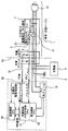
車両用充電ケーブル1に装着されている、充電回路遮断制御装置(CCIDBOX)5(図1)内に、車両用充電ケーブル1内のケーブル内電力線通信用モジュール(PLC(Power Line Communication)モジュールとも呼ばれる)7(図3)を搭載する事によって、車両用充電ケーブル1の充電回数を外部の管理装置を成す管理サーバ4(図2)で管理するものである。管理サーバ4は車両2および住居3に対して外部となる管理会社内のサーバである。なお、本発明において、住居内とは、家屋内のみでなく庭にある車両2以外の設備内をも含むものである。
In the charging circuit interruption control device (CCIDBOX) 5 (FIG. 1) attached to the
これによって、図1のCCIDBOX5が故障したとしても、例えば光ファイバーを用いた住居用の高速通信サービス(FTTH)を提供するインターネット回線8(図2)を介して、外部の管理サーバ4で、車両用充電ケーブル1の充電回数を管理するものである。
Thus, even if the
光ファイバーを用いて光通信をするには事業者側と加入者側の双方に対になった終端装置が必要である。加入者側では光ネットワークユニット(Optical Network Unit:ONU)を使用する。この構成によれば、CCIDBOX5が故障したとしても、充電回数は外部の管理サーバ4で管理されているため、充電回数の情報を失うことがなくなる。
In order to perform optical communication using an optical fiber, a pair of termination devices are required on both the provider side and the subscriber side. On the subscriber side, an optical network unit (ONU) is used. According to this configuration, even if the
車両2と成るHV/EV(Hybrid VehicleおよびElectric Vehicle)としては、プラグインハイブリッド車(PHV:Plug-in Hybrid Vehicle)が販売されている。PHVはハイブリッド車(HV)を改良し、住居用電源などから充電可能である。PHVは、市街地の近距離移動は電気自動車として走行するので、HVよりも燃費向上と二酸化炭素(CO2)排出量の削減が期待できる。PHVはガソリンエンジンを動力としても使用する。
As the HV / EV (Hybrid Vehicle and Electric Vehicle) serving as the
一方、住居でも充電できるプラグイン電気自動車(PEV)が知られている。このPEVは基本的には電気モータだけで走行するが、中にはバッテリーがなくなったときのための発電用ガソリンエンジンを搭載しているものもある。HV/EVにおいて充電する際、車両用充電ケーブル1の充電回数は決まっている。車両用充電ケーブル1の充電回数を管理したいが、現状の装置では個々の車両用充電ケーブル1の充電回数を判別する事は不可能である。
On the other hand, a plug-in electric vehicle (PEV) that can be charged even in a residence is known. This PEV basically runs only with an electric motor, but some have a gasoline engine for power generation when the battery runs out. When charging in HV / EV, the number of times of charging of the
そこで、車両用充電ケーブル1に搭載されている充電回路遮断制御装置(CCIDBOX)5内に、個別のケーブルID送信用のケーブル内電力線通信用モジュール7(図3)を持つ事で、車両用充電ケーブル1の充電回数を車両用充電ケーブル1の外部から見分けることができるようにしている。
Therefore, by having the in-cable power line communication module 7 (FIG. 3) for transmitting individual cable IDs in the charging circuit cutoff control device (CCIDBOX) 5 mounted on the charging
図1、図3のCCIDBOX5内に電力線通信を行うケーブル内電力線通信用モジュール7を内蔵している。図1の車両用充電ケーブル1の車両側先端にはガンタイプの充電コネクタ9が設けられ、ユーザが車両2の充電インレット16(図2、図3)に充電コネクタ9を接続し易いように構成されている。車両用充電ケーブル1の充電スタンド10(図2)側の端部にはアース端子が付属した住居用コンセント11(図1)が設けられている。
An in-cable power
図2は、車両2と住居3と外部の管理装置となる管理サーバ4との関係を図示したブロック図であり、車両2とインフラ間の接続状態をイメージとして示している。図2において、車両2を構成する、この一実施形態におけるEVは、車両2の内部にバッテリシステム12、電源マネジメント13、制御部14、車両内電力線通信用モジュール15、充電インレット16等を有している。
FIG. 2 is a block diagram illustrating the relationship between the
車両2のそばにはポール状の充電スタンド10が設けられ、車両2の充電インレット16と、充電スタンド10との間には、図1に示した車両用充電ケーブル1が接続されている。住居内には商用電源17から交流が引き込まれ、引込盤18内のパワー/情報マネジメント装置から、充電スタンド10が直流電力の供給を受けている。
A pole-shaped charging stand 10 is provided near the
ここで、以下に述べるPLCとHEMSについて説明する。PLCはコンセントLANまたは電力線搬送通信(PLC:Power Line Communication)とも呼ばれるが、本発明では電力線通信と呼ぶことにする。 Here, the PLC and HEMS described below will be described. The PLC is also called an outlet LAN or power line communication (PLC), but is called power line communication in the present invention.
PLCは電気を送る電力線に、情報信号を乗せて送る通信技術のことである。特別な工事は必要なく、すでに設置されている住居内の電気配線を利用してPLCネットワークを住居内に構築することが可能になる。PLCに使用される電力線通信用モジュールが市販されている。 PLC is a communication technology that sends an information signal on a power line that sends electricity. No special construction is required, and it becomes possible to construct a PLC network in the residence using the electrical wiring in the residence that has already been installed. Modules for power line communication used for PLC are commercially available.
この電力線通信用モジュールは、ノイズ抑制フィルタなどのアナログ部分も一体化したモジュールとなっており、この電力線通信用モジュールを設備内に組み込むことで容易に高速電力線通信が可能となる。次に、HEMS(home energy management system)は、センサやIT技術を活用して、住居3内のエネルギー管理を行うシステムである。 The power line communication module is a module in which an analog part such as a noise suppression filter is integrated, and high-speed power line communication can be easily performed by incorporating the power line communication module in the facility. Next, a home energy management system (HEMS) is a system that performs energy management in the dwelling 3 using sensors and IT technology.
図3は、車両用充電ケーブル1と充電器6と車両内電力線通信用モジュール15等との配線図である。図4は、充電回路遮断制御装置(CCIDBOX)5内の模式接続図である。図3において、図1にも図示したアース付きの住居用コンセント11が車両用充電ケーブル1の先端に設けられている。
FIG. 3 is a wiring diagram of the
車両用充電ケーブル1内のCCIDBOX5内にはケーブル内電力線通信用モジュール7とCCIDリレー21と電圧モニター22が接続されている。車両用充電ケーブル1の他端にはガンタイプの充電コネクタ9(図1)が接続されている。破線Y3より左側は車両2側である。車両2側の充電インレット16には、車両2内の充電器6が接続され、この充電器6に充電インレット16から電源が供給される。
An in-cable power
車両用充電ケーブル1側から出力されるケーブル接続信号PISWおよびパイロット信号CPLTが、充電インレット16を介して、車載されたパワーマネジメント電子制御ユニット(以下、PM−ECUとも言う)25に入力される。
A cable connection signal PISW and a pilot signal CPLT output from the
図3の車両用充電ケーブル1内のケーブル内電力線通信用モジュール7内に一体に組み込まれた図示しないコントロールパイロット回路は、充電コネクタ9および充電インレット16を介して車両のPM−ECU(パワーマネジメント電子制御装置)25へパイロット信号CPLTを出力する。
A control pilot circuit (not shown) integrated into the in-cable power
このパイロット信号CPLTは、CCIDBOX5内のコントロールパイロット回路から車両のPM−ECU25へ車両用充電ケーブル1の定格電流を通知するための公知の信号である。また、パイロット信号CPLTは、PM−ECU25によって操作されるパイロット信号CPLTの電位に基づいて、PM−ECU25から、車両用充電ケーブル1内のCCIDリレー21を遠隔操作するための信号としても使用される。
This pilot signal CPLT is a known signal for notifying the PM-
上記コントロールパイロット回路は、パイロット信号CPLTの電位変化に基づいてCCIDリレー21をオン/オフ制御する。このように、パイロット信号CPLTは、PM−ECU25およびCCIDBOX5の間で授受される。
The control pilot circuit performs on / off control of the
また、ケーブル接続信号PISWは、ガンタイプの充電コネクタ9に付属しているスイッチのオンオフ信号を、車両内のPM−ECU25に供給する信号である。ガンタイプの充電コネクタ9(図1)のスイッチが押されている状態では、充電開始できないようになっている。つまり、ケーブル接続信号PISWは、充電コネクタ9等の接続が正常でないときに充電ができないようにするための制御信号であり、充電コネクタ9が正常に差し込まれていることを検知する信号ともいえる。
The cable connection signal PISW is a signal for supplying an on / off signal of a switch attached to the gun-
図3の充電器6は、図2の電源マネジメント13内に存在し、図2のバッテリシステム12を充電する。また、図3のPM−ECU25は、図2の制御部14内に存在する。車両内ではCANによって制御信号が多重通信されている。
The charger 6 shown in FIG. 3 exists in the
図3の車両内のPM−ECU25には、電源制御CPU26と、DMA通信を行う充電制御HV走行制御CPU27と、電池制御CPU28が設けられている。DMA通信は、入出力制御装置が主記憶装置に直接アクセスして入出力の通信を行なう通信形態である。電源制御CPU26が立ち上がって、全体の電源マネジメントを行っている。電源制御CPU26は、HVの制御も開始させる特殊なCPUである。
The PM-
図4は、CCIDBOX5内の模式配線図である。CCIDBOX5内にCCIDリレー21が収納されており、最初はOFF状態にある。図2の充電スタンド10に車両用充電ケーブル1を接続して、家屋3内のHEMS側がCCIDBOX5に接続されると、図4の100ボルトライン30からパイロット信号CPLTが発信するようになっている。
FIG. 4 is a schematic wiring diagram in the
このパイロット信号CPLTを、車両側で感知すると、HEMS側(住居側)に電源が来ていることが判明するので、車両側がCCIDBOX5内のCCIDリレー21をオンする。パイロット信号CPLTの電圧が下がっていく最初の電圧レベルは、接続が完了したことを示すレベルである。このレベルの次に、車両側がCCIDリレー21をONすることを示す電圧レベルが存在する。
When the pilot signal CPLT is sensed on the vehicle side, it turns out that the power is coming to the HEMS side (residential side), so the vehicle side turns on the
このCCIDリレー21をONすることを示す電圧レベルをCCIDBOX5が感知すると、CCIDBOX5内のCCIDリレー21がオンする。そして、このCCIDリレー21がオンすると、電源がCCIDリレー21の二次側(図4左側)に入力されるため、CCIDBOX5内、つまりケーブル内電力線通信用モジュール7が起動する。
When the
このケーブル内電力線通信用モジュール7は、PLC電源31の供給を100ボルトライン30から受け、電力線通信信号をPLCライン32を介して100ボルトラインに重畳している。
The in-cable power
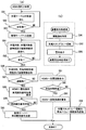
図5は、図3のCCIDBOX5内のケーブル内電力線通信用モジュール7における制御処理のフローチャートである。図6は、車両内電力線通信用モジュール15における制御処理のフローチャートを示す。図6のフローチャートは車両側におけるPLCを管理している車両内電力線通信用モジュール15内のコンピュータにて実行される。
FIG. 5 is a flowchart of control processing in the in-cable power
図7は、住居内電力線通信用モジュール20における制御処理のフローチャートを示す。この図7のフローチャートはHEMS側のPLCを管理している住居内電力線通信用モジュール20内のコンピュータにて行われる。図8は、管理サーバ4内における制御のフローチャートを示している。
FIG. 7 shows a flowchart of control processing in the in-house power
図5において、ステップS51において、車両用充電ケーブル1のCCIDBOX5内のケーブル内電力線通信用モジュール7が、車両用充電ケーブル1を特定するための車両用充電ケーブル特定情報(以下、車両用充電ケーブルIDともいう)を、記憶手段となるメモリから取り出して電力線通信を用いてHEMS側に送信する。HEMS側では受信したケーブルIDを、インターネット回線8(図2)を介して管理サーバ4に送信する。
In FIG. 5, in step S51, the in-cable power
これにより、充電回数超過情報、盗難情報等をHEMS側が管理サーバ4に問い合わせる。管理サーバ4は、問い合わせに対する回答をHEMS側に返す。HEMS側がその処理を実行している間に、車両2側では、受信した車両用充電ケーブルIDが自分のものなのかを照合用特定情報と照合して、もし自分の車両用充電ケーブル1であれば、充電回数をインクリメントして車両内の図示しないディスプレイ(表示器)に表示する。この段階では盗難情報はまだ表示されない。
Thereby, the HEMS side inquires the management server 4 about the number of times of charging excess information, theft information, and the like. The management server 4 returns an answer to the inquiry to the HEMS side. While the HEMS side is executing the process, the
CCIDBOX5では、ステップS52において漏電監視を行っている。ステップS53において、漏電が発生したと判断されると、ステップS54にて車両2側および、HEMS側(住居側)へ漏電発生を通知する。
In
図6の(a)部分において、車両側のPLC処理を説明する。車両用充電ケーブル1が接続されて、つまり、プラグインされてCCIDBOX5内のCCIDリレー21がオンして、車両2に電源がきて、車両用充電ケーブルID(単に、ケーブルIDともいう)を送信できる状態から説明する。
In the part (a) of FIG. 6, the PLC process on the vehicle side will be described. When the
図6の(a)において、車両側PLC処理が開始され、ステップS61でケーブルID受信待ちの状態となる。車両用充電ケーブル1が車両2にプラグインされ、充電できるようになると、CCIDBOX5内から車両2側とHEMS側に対してケーブルIDが送信される。ステップS62において、車両内電力線通信用モジュール15が、ケーブルIDを受信したかどうか判定し、受信した場合は、ステップS63に進む。
In FIG. 6A, vehicle-side PLC processing is started, and a cable ID reception waiting state is entered in step S61. When the
一方、CCIDBOX5内のケーブル内電力線通信用モジュール7がケーブルIDを送信すると、HEMS側にてPLCを管理している住居内電力線通信用モジュール20(図92)内のコンピュータがケーブルIDを受信する。
On the other hand, when the in-cable power
そして、まずその車両用充電ケーブル1が自分の所有している車両用充電ケーブル1であるかどうかを判定するために、記憶されている照合用特定情報と照合する。自分の車両用充電ケーブル1であった場合、その情報を、HEMS側から車両2側に電力線通信で送信する。自分の車両用充電ケーブル1でない場合は、盗難情報を発生する。
First, in order to determine whether or not the
車両2側では、図5のステップS63で、車両用充電ケーブル1の充電回数、充電回数超過情報、盗難情報を受信待ちしている。充電回数の情報が受信できたら、車両用充電ケーブル1の充電回数をインクリメントし、車両2内の表示器に表示する。
On the
住居内電力線通信用モジュール20では、外部サーバ4と連携して充電回数を管理しており、充電回数超過と判断する基準値(設定値ともいう)を持っている。充電回数超過と判断すると、住居内電力線通信用モジュール20は、車両側に充電回数超過情報を送信する。
The in-house power
ステップS64にて、盗難情報またはケーブル充電回数超過情報を受信した場合、ステップS65に進み、盗難情報が受信されて盗難ケーブルであるか否かを判定する。ステップS66で盗難ケーブルである場合は、車両内のディスプレイにて盗難警告表示を行う。一方、住居内電力線通信用モジュール20(HEMS側)は、盗難ケーブルとわかれば車両識別番号取得要求を車両2側に送信する。
If the theft information or the cable charging count excess information is received in step S64, the process proceeds to step S65 to determine whether the theft information is received and the cable is a stolen cable. If it is a theft cable in step S66, a theft warning is displayed on the display inside the vehicle. On the other hand, the residential power line communication module 20 (HEMS side) transmits a vehicle identification number acquisition request to the
ステップS67で、HEMS側からの車両識別番号取得要求が車両2側で受信されていれば、車両識別信号を、ステップS68にて、電力線通信を介して先ずHEMS側に送信する。一方、住居内電力線通信用モジュール20は、インターネット回線8(図1)を介して、外部の管理サーバ4に盗難ケーブルで充電した車両識別番号を送信する。
If a vehicle identification number acquisition request from the HEMS side is received on the
ステップS65において、NOと判定され、ステップS69で充電回数超過と判定された場合、ステップS70において、充電回数超過情報を車両内のディスプレイ(表示器)に表示させる。 If it is determined as NO in step S65 and it is determined that the number of times of charging has been exceeded in step S69, the information on the number of times of charging has been exceeded is displayed on a display (display) in the vehicle in step S70.
なお、充電回数超過表示は、HEMS側つまり家屋3(図2)内のディスプレイでも車両2内のディスプレイでも行う。また、車両用充電ケーブル1を接続するたびに、外部の管理サーバ4のほうに、充電回数と盗難の有無を報告している。外部サーバ4にて報告内容を記録し管理している。
The overcharge display is performed on the HEMS side, that is, the display in the house 3 (FIG. 2) or the display in the
ステップS69において、車両用充電ケーブル1の充電回数が超過していない場合、ステップS71において、HEMS側の充電スタンドリレーの接続信号である充電スタンド接続信号が出力されているか否かを判定し、出力されているときは、ステップS72に進み、車両側の充電メインリレーを接続し、車両2への充電を開始する。
If the number of times of charging of the
なお、図6の(a)の車両側のPLC処理と平行して(パラレルに)、図6の(b)における漏電発生時処理が行われている。ここでは、ステップS73において、CCIDBOX5内のケーブル内電力線通信用モジュール7から漏電通知情報を受信すると、ステップS74において、車両側の充電メインリレーを切断する。次にステップS75において、警告表示を車両2内にて行う。
In parallel with the PLC processing on the vehicle side in FIG. 6A, the processing at the time of occurrence of electric leakage in FIG. 6B is performed. Here, when the leakage notification information is received from the in-cable power
以下において、図7を用いて、HEMS側のPLC処理を説明する。HEMS側処理では、住居内電力線通信用モジュール20(図2)が、ステップS81でCCIDBOX5からの車両用充電ケーブルIDの受信を待つ。
Hereinafter, the PLC processing on the HEMS side will be described with reference to FIG. In the HEMS side processing, the in-house power line communication module 20 (FIG. 2) waits for reception of the vehicle charging cable ID from the
ステップS82において、車両用充電ケーブルIDを受信すると、ステップS83に進み、インターネット回線8(図2)を経由し、車両用充電ケーブル1の充電回数および、盗難情報を管理している外部の管理サーバ4(管理装置)へ住居内電力線通信用モジュール20がアクセスする。
In step S82, when the vehicle charging cable ID is received, the process proceeds to step S83, and the external management server managing the number of times of charging of the
住居内電力線通信用モジュール20が管理サーバ4にアクセスした結果、ステップS84において、充電回数、充電回数超過情報、盗難情報等を管理サーバ4から住居内電力線通信用モジュール20が受信する。
As a result of the in-house power
ステップS85にて、充電回数、充電回数超過情報、盗難情報等を管理サーバ4から住居内電力線通信用モジュール20が受信できたら、この受信情報を、ステップS86で住居内電力線通信用モジュール20から車両内電力線通信用モジュール15へ送信する。
In step S85, if the in-house power
なお、インターネット回線8の故障等で充電回数、充電回数超過情報、盗難情報等を受信できない場合は、住居内電力線通信用モジュール20内の記憶手段で保持している情報に基づいて、住居内電力線通信用モジュール20内で自ら充電回数を更新し、自ら充電回数超過判定を行って、超過しているときは充電回数超過情報を生成する。
In addition, when the number of times of charging, the number of times of charging exceeded, theft information, etc. cannot be received due to a failure of the
また、自らケーブルIDを本来の自分のケーブルIDと比較して、異なる場合は、盗難情報等を生成して、これらの生成情報を、住居内電力線通信用モジュール20から車両内電力線通信用モジュール15へ送信する。
If the cable ID is different from the original cable ID by itself, theft information or the like is generated, and the generated information is transferred from the residential power
また仮に、住居内電力線通信用モジュール20において、充電回数等の情報が失われることがあっても、同様の情報が、外部サーバ4でも管理されているため、外部サーバ4からの情報で失われた情報を回復することもでき、外部サーバ4からの情報で、充電回数超過後の処理を継続することもできる。
In addition, even if information such as the number of times of charging may be lost in the residential power
ステップS87において、もし車両用充電ケーブル1が盗難物であった場合は、住居内電力線通信用モジュール20は、ステップS88で、HEMS側(住居内)のディスプレイ(表示器)で警告表示を行い、車両のユーザに知らせる。
In step S87, if the
かつ、盗難された車両用充電ケーブル1を使用している車両2の車両識別番号を取得するために、電力線通信を用いて車両内電力線通信用モジュール15に車両識別番号を要求する。このとき、どの車に盗難されたケーブルを使用しているかVINに関するコードを要求する(ナンバープレート番号でも良い)。
And in order to acquire the vehicle identification number of the
なお、VIN(Vehicle Identification Number)は、自動車産業界で個々の車両を識別するために使用している一意のシリアル番号である。ステップS89で車両識別番号を受信すると、ステップS90で、管理サーバ4へ車両識別番号を送信する。 Note that VIN (Vehicle Identification Number) is a unique serial number used to identify individual vehicles in the automobile industry. When the vehicle identification number is received in step S89, the vehicle identification number is transmitted to the management server 4 in step S90.
ステップS87において、盗難物でない場合は、ステップS91に進み、住居内電力線通信用モジュール20は、HEMS側(住居内)で充電回数表示を行い、車両のユーザに知らせる。ステップS92において、充電回数を超過している場合は、ステップS93でHEMS側に回数超過を警告する。
In step S87, if it is not a stolen object, the process proceeds to step S91, and the in-house power
ステップS92において、管理サーバ4からの情報により充電回数を超過していない場合は、ステップS94において、電力線通信で充電スタンド10(図2)内の充電スタンドリレーを接続し、車両側に充電スタンドリレー接続信号を送信する。 In step S92, if the number of times of charging is not exceeded by the information from the management server 4, in step S94, the charging station relay in the charging station 10 (FIG. 2) is connected by power line communication, and the charging station relay is connected to the vehicle side. Send a connection signal.
図7の(b)の枠内のフローチャートは、図7の(a)のHMES側の制御処理を示すメインのフローチャートとパラレルに制御が進行している漏電発生時の処理を示す。漏電発生時の処理はいつでも起こりうる。図7の(b)における漏電発生時処理では、ステップS96において、CCIDBOX5内のケーブル内電力線通信用モジュール7から漏電通知情報を受信すると、ステップS97において、充電スタンド10(図2)内の充電スタンドリレーを切断する。次に、ステップS98において、警告表示をHEMS側のPLC処理を管理するコンピュータのディスプレイ等にて行う。
The flowchart in the frame of (b) of FIG. 7 shows the process at the time of occurrence of electric leakage in which the control proceeds in parallel with the main flowchart showing the control process on the HMES side of (a) of FIG. Processing at the time of leakage can occur at any time. 7B, when the leakage notification information is received from the in-cable power
図8は、外部の管理会社内の管理サーバ4の制御を示すフローチャートである。ステップS81において、充電回数、充電回数超過情報、盗難情報の問い合わせがあると、ステップS82において、管理サーバ4の記憶手段(メモリ)内の充電回数、充電超過情報、盗難情報の演算ならびに検索が行われ、ステップS83で、インターネット回線8(図2)と電力線通信を介して、HEMS内のコンピュータに、充電回数、充電回数超過情報、盗難情報を送信する。次に、ステップS84で、車両識別信号を受信したときには、ステップS85で、車両識別番号を管理サーバ4内の記憶手段に登録し、犯罪検索等に備える。 FIG. 8 is a flowchart showing the control of the management server 4 in the external management company. In step S81, when there is an inquiry about the number of times of charging, information on excess charging times, and theft information, calculation and search of the number of times of charging, excess charging information, and theft information in the storage means (memory) of the management server 4 are performed in step S82. In step S83, the number of times of charging, the number of times of overcharging, and theft information are transmitted to the computer in the HEMS via the Internet line 8 (FIG. 2) and power line communication. Next, when a vehicle identification signal is received in step S84, the vehicle identification number is registered in the storage means in the management server 4 in step S85 to prepare for a crime search or the like.
図9から図11は、車両のユーザ、充電回路遮断制御装置(CCIBOX)、車両、HEMS間の電力線通信を利用した信号の流れ等を示すシーケンス図である。図9は、ユーザが車両用充電ケーブル1をプラグインした後の車両2のユーザ、充電回路遮断制御装置(CCIBOX5)、車両2、HEMS、管理装置(管理サーバ4)間の電力線通信を利用した信号の流れ等を示すシーケンス図である。
FIG. 9 to FIG. 11 are sequence diagrams showing a signal flow using power line communication between a vehicle user, a charging circuit cutoff control device (CCIBOX), a vehicle, and a HEMS. FIG. 9 uses power line communication between the user of the
図9において、車両用充電ケーブル1を車両2と充電スタンド10間に接続して、プラグインすると、CCIBOX5内のケーブル内電力線通信用モジュール7が起動される。次に、車両用充電ケーブルID(ケーブルID)をCCIBOX5から送信する。HEMS側では受信したケーブルIDを管理サーバ4に送信する。この送信は、充電回数、充電回数超過情報、盗難情報を問い合わせるためである。
In FIG. 9, when the
管理サーバ4は、回答をHEMSに返す。HEMS側がその処理を実行している間に、車両2側では、受信したケーブルIDが自分のものなのかを判定して、もし自分のケーブルIDであれば、充電回数をインクリメントして車両2内に表示する。この段階では盗難情報はまだ表示されない。このように図9では、充電回数、充電回数超過判定、盗難情報に関するHEMS側から管理サーバ4への問い合わせの並列処理が行われる。
The management server 4 returns an answer to the HEMS. While the HEMS side is executing the process, the
図10は、仮に、車両用充電ケーブルが盗難ケーブルであったとき、仮に充電回数超過のとき、仮に充電可能なときの各条件での条件分岐処理を実行する車両2、HEMS、管理装置(管理サーバ4)間の電力線通信を利用した信号の流れ等を示すシーケンス図である。
FIG. 10 shows a
車両2側およびHEMS側で、盗難ケーブルであると判明したときは、車両2側とHEMS側とで警告表示が行われる。また、HEMS側から車両2に車両識別番号を要求する。要求に対して回答された車両識別番号は、HEMS側から管理サーバ4に送信される。充電回数超過判定がなされると、車両2とHEMS側で警告表示が行われる。
When the
車両用充電ケーブル1を車両2と充電スタンド10間に接続して、盗難でもなく充電回数超過でもなく正常に充電可能と判断されると、HEMS側から充電スタンドリレー接続信号が送信される。また、車両内の充電メインリレーが接続される。
When the
充電回数を管理しているのは外部サーバ4である。しかし、充電する前に自分の車両用充電ケーブルIDをHEMS側で確認できれば、外部サーバ4から許可情報が出なくても、充電可能と判断して充電できるように許可信号を出力してもよい。これにより、管理サーバ4との通信が一時的に不可能になっても車両2を充電することが可能である。
The external server 4 manages the number of times of charging. However, if the vehicle charging cable ID can be confirmed on the HEMS side before charging, a permission signal may be output so that charging can be performed by determining that charging is possible even without permission information from the external server 4. . Thereby, even if communication with the management server 4 becomes temporarily impossible, the
図11は、漏電発生通知があったときの条件処理を示す、充電回路遮断制御装置(CCIBOX)、車両2、HEMS間の電力線通信を利用した信号の流れ等を示すシーケンス図である。漏電発生通知は、CCIDBOX5から車両2とHEMS側に通知される。車両2内では充電メインリレーが切断され、警告表示がメータパネル内のディスプレイにて行われる。HEMS側では充電スタンド10内の充電スタンドリレーを切断し、住居内のディスプレイで警告表示がなされる。
FIG. 11 is a sequence diagram illustrating a signal process using power line communication between the charging circuit interruption control device (CCIBOX), the
(第2実施形態)
次に、本発明の第2実施形態について説明する。なお、以降の各実施形態においては、上述した第1実施形態と同一の構成要素には同一の符号を付して説明を省略し、異なる構成および特徴について説明する。図12は、本発明の第2実施形態を示す、HEMS側における住居内電力線通信用モジュールによる制御処理の一部フローチャートを示す。
(Second Embodiment)
Next, a second embodiment of the present invention will be described. In the following embodiments, the same components as those in the first embodiment described above are denoted by the same reference numerals, description thereof will be omitted, and different configurations and features will be described. FIG. 12 shows a partial flowchart of the control process by the residential power line communication module on the HEMS side, showing the second embodiment of the present invention.
充電回数が超過したら、充電が開始されないが、充電回数が超過する前段階(充電回数超過近傍)で予告警報を住居内または車両内で発しても良い。このためには回数管理を二段階に管理する。第1段目は充電規制を予告し、この後、10回以内の充電で充電不可能となることを通報する。図12において、二段階警報制御を示す一部フローチャートを示すが、その他のフローチャート部分は図7と同じである。 If the number of times of charging is exceeded, charging is not started, but a warning warning may be issued in the residence or in the vehicle at a stage before the number of times of charging exceeds (near the number of times of charging). For this purpose, the number management is managed in two stages. The first stage notifies the charging regulation, and then informs that charging is not possible after charging within 10 times. FIG. 12 shows a partial flowchart showing the two-stage alarm control, but the other flowchart parts are the same as those in FIG.
図12のステップS91aにおいて、充電回数超過がまもなくであると判定されたときは、ステップS91bに進んで、HEMS内のディスプレイまたは/および車両2側のディスプレイで、回数超過がまもなくであることを表示させる。なお、充電回数超過がまもなくであるかどうかは、充電回数超過となるまでに残された充電回数が予め定めた回数になったか否かで判定する。
If it is determined in step S91a in FIG. 12 that the number of charging times will soon be exceeded, the process proceeds to step S91b, and the display in the HEMS and / or the display on the
(第3実施形態)
次に、本発明の第3実施形態について説明する。上述した実施形態と異なる特徴部分を説明する。図13は、本発明の第3実施形態を示す、HEMS側における住居内電力線通信用モジュールによる制御処理の一部フローチャートを示す。
(Third embodiment)
Next, a third embodiment of the present invention will be described. Features different from the above-described embodiment will be described. FIG. 13 shows a partial flowchart of the control process by the residential power line communication module on the HEMS side, showing the third embodiment of the present invention.
充電回数が超過したら、充電が開始されないが、所定時間または所定電力量充電してから充電を停止させても良い。図13は、所定時間または所定電力量充電制御を示す一部フローチャートであり、その他のフローチャート部分は、図7と同じである。 If the number of times of charging is exceeded, charging is not started, but charging may be stopped after charging for a predetermined time or a predetermined amount of power. FIG. 13 is a partial flowchart showing the predetermined time or predetermined power amount charging control, and other flowchart parts are the same as those in FIG.
図13のステップS93aにおいて、所定時間または所定電力量充電を行う。この所定時間または所定電力量充電においては、ステップS94と同様に、電力線通信で充電スタンド10(図2)内の充電スタンドリレーを接続し、車両側に充電スタンドリレー接続信号を送信する。しかし、所定時間または所定電力量の充電が完了すると、ステップS93に進み、HEMSへ回数超過を警告し、HEMS側の指令で充電を中止させる。 In step S93a of FIG. 13, charging is performed for a predetermined time or a predetermined amount of power. In this predetermined time or predetermined power amount charging, as in step S94, the charging station relay in the charging station 10 (FIG. 2) is connected by power line communication, and a charging station relay connection signal is transmitted to the vehicle side. However, when charging for a predetermined time or a predetermined amount of power is completed, the process proceeds to step S93, where the HEMS is warned that the number of times has been exceeded, and charging is stopped by a command on the HEMS side.
(その他の実施形態)
本発明は上述した実施形態にのみ限定されるものではなく、次のように変形または拡張することができる。例えば、上述の第1実施形態では、家屋内の住居内電力線通信用モジュール20とインターネット回線8を経由して、外部の管理サーバ4に、車両用充電ケーブル1の充電回数等を登録したが、図2の充電スタンド10内の充電スタンド内電力線通信用モジュール(図示せず)また引込盤18内のパワー/情報マネジメント装置内の引込盤内電力線通信用モジュール(図示せず)を経由して外部の管理サーバ4に車両用充電ケーブル1の充電回数等を登録しても良い。つまり、本発明の住居内電力通信モジュールは、HEMS側に設置されていれば良く、家屋3(図2)内に限定されない。
(Other embodiments)
The present invention is not limited to the above-described embodiments, and can be modified or expanded as follows. For example, in the above-described first embodiment, the number of times of charging the
また、外部通信網としてインターネット回線8を使用したが、電力線通信網(商用電源の配電網を介した通信回線)を介して図2の矢印Y2、Y3のように、外部の管理サーバ4に車両用充電ケーブル1の充電回数等を登録しても良い。更には、車両内電力線通信用モジュール15から図示しない車載無線機を介して無線LANを経由して外部の管理サーバ4に車両用充電ケーブル1の充電回数等を登録しても良い。
Further, although the
車両識別番号と共にロケーション情報を外部サーバ4に送信して、充電スタンド10または車両2の位置情報を通知してもよい。この場合、車両2からのナビゲーションシステムの情報を取得しても良い。また、充電スタンド10や電柱の固有番号で位置が判明する場合は、充電スタンド10の固有番号や電柱の固有番号を送信しても良い。
The location information together with the vehicle identification number may be transmitted to the external server 4 to notify the location information of the charging
CCIDBOX5の中の漏電ブレーカが漏電を感知し、CCIDBOXの外部に漏電を通知したが、上記実施形態では管理サーバ4まで通知しなかった。しかし、管理サーバ4側で漏電時の対策を取れる体制がある場合は通報してもよい。また、管理サーバ4とHEMS側とで充電回数等の情報が異なる場合は、管理サーバ4側の情報を優先させても良い。
The earth leakage breaker in the
なお、充電回数が超過したかどうかは、管理サーバ4側で管理しているが、充電を直接的に規制ないし停止させるのはHEMS側または車両2側である。しかし、管理サーバ4が直接的に充電を規制ないし停止させても良い。
Whether or not the number of times of charging has been exceeded is managed on the management server 4 side, but it is the HEMS side or the
また、上記実施形態においては、充電回数超過情報が車両2内で表示されると、充電できないが、車両2内またはHEMS側からのリセット操作により充電超過にもかかわらず、所定分の充電を許可するようにしても良い。
Moreover, in the said embodiment, when the number-of-charges excess information is displayed in the
1 車両用充電ケーブル
4 管理サーバ(管理装置)
5 充電回路遮断制御装置(CCIDBOX)
6 充電器
7 ケーブル電力線通信用モジュール
8 インターネット回線
9 充電コネクタ
10 充電スタンド
11 住居用コンセント
15 車両内電力線通信用モジュール
16 充電インレット
20 家屋内電力線通信用モジュール(住居内電力線通信用モジュール)
21 CCIDリレー
22 電圧モニター
25 パワーマネジメント電子制御ユニット(PM−ECU)
26 電源制御CPU
30 100ボルトライン
31 PLC電源
32 PLCライン
CPLT パイロット信号
PISW ケーブル接続信号
S81 車両用充電ケーブル特定情報(車両用充電ケーブルID)を受信する手段
1 Vehicle charging cable 4 Management server (management device)
5 Charge circuit cutoff control device (CCIDBOX)
6
21
26 Power control CPU
30 100
Claims (12)
前記車両用充電ケーブルに装着され、前記車両用充電ケーブルを個別に特定するための車両用充電ケーブル特定情報を記憶する充電回路遮断制御装置と、
前記充電回路遮断制御装置内に搭載されたケーブル内電力線通信用モジュールと、
前記車両用充電ケーブルの外部に設けられた装置であって、前記車両用充電ケーブル特定情報を、前記ケーブル内電力線通信用モジュールを用いた電力線通信により、充電する毎に取得し、前記車両用充電ケーブルにおける充電回数を管理する管理装置とを有することを特徴とする車両用充電ケーブル管理システム。 A vehicle charging cable management system for managing the number of times of charging of a vehicle charging cable for charging a vehicle with electric power from a residence and notifying a user,
A charging circuit cutoff control device that is mounted on the vehicle charging cable and stores vehicle charging cable specifying information for individually specifying the vehicle charging cable; and
In-cable power line communication module mounted in the charging circuit cutoff control device,
A device provided outside the vehicle charging cable, wherein the vehicle charging cable specifying information is acquired every time charging is performed by power line communication using the in-cable power line communication module, and the vehicle charging is performed. A vehicle charging cable management system comprising: a management device that manages the number of times of charging in the cable.
特徴としている。 2. The vehicle charging cable management according to claim 1, wherein the management device includes a management server located at a place other than the vehicle and the residence on a network connected to the in-cable power line communication module. system.
It is a feature.
特徴としている。 3. The vehicle charging according to claim 1, wherein when the number of times of charging of the vehicle charging cable exceeds a reference value, the management device generates charging number excess information for stopping charging. 4. Cable management system.
It is a feature.
前記車両用充電ケーブルにより前記車両に給電する電力線を通信線として利用した車両内電力線通信用モジュールが設けられ、
前記車両内電力線通信用モジュールを介して前記車両用充電ケーブルから、前記車両用充電ケーブルを個別に特定するための車両用充電ケーブル特定情報を受信する手段と、
前記車両用充電ケーブル特定情報を受信した場合に、前記車両内電力線通信用モジュールを介して前記車両用充電ケーブル側から、前記車両用充電ケーブルの充電回数が基準値を超過した場合に充電を停止させるための充電回数超過情報を待ち受け、前記充電回数超過情報を受信した場合に前記車両内にて表示器に警告表示させる手段とを備えることを特徴とする車両充電用電子制御装置。 An electronic control device for charging a vehicle is provided inside a vehicle that is charged with electric power from a residence using a vehicle charging cable, and starts charging by turning on a main relay in the vehicle before charging. And
An in-vehicle power line communication module using a power line that feeds the vehicle with the vehicle charging cable as a communication line is provided,
Means for receiving vehicle charging cable specifying information for individually specifying the vehicle charging cable from the vehicle charging cable via the in-vehicle power line communication module;
When the vehicle charging cable identification information is received, charging is stopped when the number of times of charging of the vehicle charging cable exceeds a reference value from the vehicle charging cable side via the in-vehicle power line communication module An electronic control device for charging a vehicle comprising: means for waiting for overcharge count information for causing the display to display a warning on a display in the vehicle when the overcharge count information is received.
前記住居内に設けられ、前記車両用充電ケーブルより前記車両に給電する電力線を通信線として利用した住居内電力線通信用モジュールと、
前記車両を充電する毎に、前記住居内電力線通信用モジュールを介して前記車両用充電ケーブルから、前記車両用充電ケーブルを個別に特定するための車両用充電ケーブル特定情報を受信する手段と、
前記車両用充電ケーブル特定情報を受信した場合に、前記住居内電力線通信用モジュールを介する電力線通信により、前記車両用充電ケーブル特定情報を外部の管理装置に送信し、該管理装置側からの、前記車両用充電ケーブルの充電回数が基準値を超過した場合に充電を停止させるための充電回数超過情報を待ち受け、前記充電回数超過情報を受信した場合に前記住居内にて表示器に警告表示させる手段と、
前記充電回数超過情報を受信した場合に、前記住居内電力線通信用モジュールによって、前記車両用充電ケーブルを介して前記車両に前記充電回数超過情報を送信する手段を備えることを特徴とする住居内充電用電子制御装置。 In order to charge the vehicle with the electric power from the residence via the charging cable for the vehicle, charging is started by inserting a power supply side relay that connects the power source to the outlet that supplies power to the charging cable for the vehicle. Electronic control device for charging in a house,
A module for dwelling power line communication that is provided in the dwelling and uses a power line that supplies power to the vehicle from the vehicular charging cable as a communication line;
Means for receiving vehicle charging cable identification information for individually identifying the vehicle charging cable from the vehicle charging cable via the residential power line communication module each time the vehicle is charged;
When the vehicle charging cable identification information is received, the vehicle charging cable identification information is transmitted to an external management device by power line communication via the residential power line communication module, from the management device side, Means for waiting for charging frequency excess information for stopping charging when the charging frequency of the vehicle charging cable exceeds a reference value and displaying a warning on the display in the residence when the charging frequency excess information is received When,
Residential charging, comprising: means for transmitting the excess charging frequency information to the vehicle via the vehicle charging cable by the residential power line communication module when receiving the excessive charging frequency information. Electronic control device.
前記車両用充電ケーブルからの前記車両用充電ケーブル特定情報を受信した場合に、記憶されている前記車両用充電ケーブルの充電回数を更新する手段と、
前記車両用充電ケーブルの充電回数を更新する手段が充電回数を更新する場合に、更新された前記充電回数が基準値を超過していないか否かを判定する手段と、
前記充電回数が前記基準値を超過しておらず、かつ前記自身の車両用充電ケーブルであると判定されたときに、前記管理装置からの許可情報がなくても、前記車両用充電ケーブルによる前記車両の充電を許可する許可信号を送信する手段を備えることを特徴とする請求項10に記載の住居内充電用電子制御装置。 When the vehicle charging cable identification information is received from the vehicle charging cable, the vehicle charging cable identification information is compared with the stored identification information stored in the vehicle charging cable. Means for determining whether there is,
Means for updating the stored charging count of the vehicle charging cable when receiving the vehicle charging cable specifying information from the vehicle charging cable;
Means for determining whether or not the updated number of times of charging exceeds the reference value when the means for updating the number of times of charging of the vehicle charging cable updates the number of times of charging;
When it is determined that the number of times of charging does not exceed the reference value and is the own vehicle charging cable, even if there is no permission information from the management device, the vehicle charging cable does not The in-house charging electronic control device according to claim 10, further comprising means for transmitting a permission signal for permitting charging of the vehicle.
前記車両用充電ケーブルの途中に筐体を備え、該筐体内に前記車両用充電ケーブルの漏電検出器と断線検出器を備えた充電回路遮断制御装置を備え、
前記充電回路遮断制御装置内に前記車両用充電ケーブルを個別に特定するための車両用充電ケーブル特定情報が記憶された記憶手段と、前記電力線を介して通信を行うための電力線通信モジュールとを有することを特徴とする車両用充電ケーブル。 A charging cable for a vehicle that relays between a vehicle inlet and an outlet in the residence in order to charge the vehicle with a power line from the residence,
Provided with a casing in the middle of the vehicle charging cable, and equipped with a charging circuit cutoff control device provided with a leakage detector and a disconnection detector of the vehicle charging cable in the casing,
Storage means storing vehicle charging cable specifying information for individually specifying the vehicle charging cable in the charging circuit cutoff control device, and a power line communication module for performing communication via the power line The charging cable for vehicles characterized by the above-mentioned.
Priority Applications (1)
| Application Number | Priority Date | Filing Date | Title |
|---|---|---|---|
| JP2010284687A JP2012135111A (en) | 2010-12-21 | 2010-12-21 | Vehicle charge cable management system |
Applications Claiming Priority (1)
| Application Number | Priority Date | Filing Date | Title |
|---|---|---|---|
| JP2010284687A JP2012135111A (en) | 2010-12-21 | 2010-12-21 | Vehicle charge cable management system |
Publications (1)
| Publication Number | Publication Date |
|---|---|
| JP2012135111A true JP2012135111A (en) | 2012-07-12 |
Family
ID=46650022
Family Applications (1)
| Application Number | Title | Priority Date | Filing Date |
|---|---|---|---|
| JP2010284687A Pending JP2012135111A (en) | 2010-12-21 | 2010-12-21 | Vehicle charge cable management system |
Country Status (1)
| Country | Link |
|---|---|
| JP (1) | JP2012135111A (en) |
Cited By (8)
| Publication number | Priority date | Publication date | Assignee | Title |
|---|---|---|---|---|
| JP2014043207A (en) * | 2012-08-28 | 2014-03-13 | Auto Network Gijutsu Kenkyusho:Kk | Communication system, on-vehicle communication device and repeating device |
| WO2016002218A1 (en) * | 2014-07-02 | 2016-01-07 | パナソニックIpマネジメント株式会社 | Leakage protection device and leakage protection system |
| JPWO2014167889A1 (en) * | 2013-04-11 | 2017-02-16 | ソニー株式会社 | Battery device |
| EP3663124A1 (en) * | 2018-12-07 | 2020-06-10 | David Timothy Patrick Watson | System and method for controlling charging of an electric energy storage system of an electric vehicle |
| CN111284353A (en) * | 2018-12-07 | 2020-06-16 | 欧姆技术有限公司 | System and method for controlling charging of an electrical energy storage system of an electric vehicle |
| WO2021050186A1 (en) * | 2019-09-12 | 2021-03-18 | Zayo Group, Llc | Integrated data and charging station |
| EP3831644A3 (en) * | 2019-02-12 | 2021-08-25 | Massimo Ferrari | Charging system and method of a battery of an electric vehicle |
| JP2022547276A (en) * | 2019-09-12 | 2022-11-11 | ザヨ グループ,エルエルシー | Integrated data and charging station |
Citations (9)
| Publication number | Priority date | Publication date | Assignee | Title |
|---|---|---|---|---|
| JPH11162570A (en) * | 1997-11-26 | 1999-06-18 | Nec Corp | Connector service life warning display method and device therefor |
| JP2005198445A (en) * | 2004-01-08 | 2005-07-21 | Yamaha Motor Co Ltd | Charging management system and charging management device |
| JP2006031259A (en) * | 2004-07-14 | 2006-02-02 | Nippon Telegr & Teleph Corp <Ntt> | Power supply device |
| JP2008141795A (en) * | 2006-11-29 | 2008-06-19 | Sony Corp | Portable electronic equipment system, electric power transmission cable, and portable electronic equipment |
| JP2009071989A (en) * | 2007-09-13 | 2009-04-02 | Toyota Motor Corp | Vehicle charging controller and vehicle |
| JP2010110051A (en) * | 2008-10-28 | 2010-05-13 | Panasonic Electric Works Co Ltd | Charging system |
| JP2010124538A (en) * | 2008-11-17 | 2010-06-03 | Toyota Motor Corp | Charging cable for electric vehicle and method of controlling charging cable |
| JP2010161911A (en) * | 2009-01-09 | 2010-07-22 | Alpha Corp | Charging cable for electric vehicle |
| JP2011259613A (en) * | 2010-06-09 | 2011-12-22 | Nissan Motor Co Ltd | Charging control device and control method |
-
2010
- 2010-12-21 JP JP2010284687A patent/JP2012135111A/en active Pending
Patent Citations (9)
| Publication number | Priority date | Publication date | Assignee | Title |
|---|---|---|---|---|
| JPH11162570A (en) * | 1997-11-26 | 1999-06-18 | Nec Corp | Connector service life warning display method and device therefor |
| JP2005198445A (en) * | 2004-01-08 | 2005-07-21 | Yamaha Motor Co Ltd | Charging management system and charging management device |
| JP2006031259A (en) * | 2004-07-14 | 2006-02-02 | Nippon Telegr & Teleph Corp <Ntt> | Power supply device |
| JP2008141795A (en) * | 2006-11-29 | 2008-06-19 | Sony Corp | Portable electronic equipment system, electric power transmission cable, and portable electronic equipment |
| JP2009071989A (en) * | 2007-09-13 | 2009-04-02 | Toyota Motor Corp | Vehicle charging controller and vehicle |
| JP2010110051A (en) * | 2008-10-28 | 2010-05-13 | Panasonic Electric Works Co Ltd | Charging system |
| JP2010124538A (en) * | 2008-11-17 | 2010-06-03 | Toyota Motor Corp | Charging cable for electric vehicle and method of controlling charging cable |
| JP2010161911A (en) * | 2009-01-09 | 2010-07-22 | Alpha Corp | Charging cable for electric vehicle |
| JP2011259613A (en) * | 2010-06-09 | 2011-12-22 | Nissan Motor Co Ltd | Charging control device and control method |
Cited By (12)
| Publication number | Priority date | Publication date | Assignee | Title |
|---|---|---|---|---|
| JP2014043207A (en) * | 2012-08-28 | 2014-03-13 | Auto Network Gijutsu Kenkyusho:Kk | Communication system, on-vehicle communication device and repeating device |
| JPWO2014167889A1 (en) * | 2013-04-11 | 2017-02-16 | ソニー株式会社 | Battery device |
| WO2016002218A1 (en) * | 2014-07-02 | 2016-01-07 | パナソニックIpマネジメント株式会社 | Leakage protection device and leakage protection system |
| JPWO2016002218A1 (en) * | 2014-07-02 | 2017-04-27 | パナソニックIpマネジメント株式会社 | Earth leakage protection device and earth leakage protection system |
| AU2015285887B2 (en) * | 2014-07-02 | 2018-07-05 | Panasonic Intellectual Property Management Co., Ltd. | Residual current protection device and residual current protection system |
| EP3663124A1 (en) * | 2018-12-07 | 2020-06-10 | David Timothy Patrick Watson | System and method for controlling charging of an electric energy storage system of an electric vehicle |
| CN111284353A (en) * | 2018-12-07 | 2020-06-16 | 欧姆技术有限公司 | System and method for controlling charging of an electrical energy storage system of an electric vehicle |
| EP3831644A3 (en) * | 2019-02-12 | 2021-08-25 | Massimo Ferrari | Charging system and method of a battery of an electric vehicle |
| WO2021050186A1 (en) * | 2019-09-12 | 2021-03-18 | Zayo Group, Llc | Integrated data and charging station |
| US11390182B2 (en) | 2019-09-12 | 2022-07-19 | Zayo Group, Llc | Integrated data and charging station |
| JP2022547276A (en) * | 2019-09-12 | 2022-11-11 | ザヨ グループ,エルエルシー | Integrated data and charging station |
| JP7470782B2 (en) | 2019-09-12 | 2024-04-18 | ザヨ グループ,エルエルシー | Integrated data and charging station |
Similar Documents
| Publication | Publication Date | Title |
|---|---|---|
| JP2012135111A (en) | Vehicle charge cable management system | |
| US11901523B2 (en) | Vehicular battery charger, charging system, and method with in-vehicle display of charge time and remote control | |
| US20130110340A1 (en) | Electric vehicle, charging stand, and method for charging the electric vehicle | |
| JP6160928B2 (en) | In-vehicle device and charge / discharge system | |
| US20100194529A1 (en) | Management system for charging plug-in vehicle | |
| CN105391103B (en) | Off-board charger for high voltage battery charging | |
| US20140249976A1 (en) | Accounting system and ev charging system | |
| WO2011045925A1 (en) | Power source device and vehicle | |
| EP2692570B1 (en) | In-vehicle charging device | |
| JP2012235679A (en) | Charging systems for use with electric vehicles and methods of monitoring the same | |
| JP2012143026A (en) | Charger for vehicle | |
| KR20160033511A (en) | Cable installment type charging control apparatus and method thereof | |
| US9108522B2 (en) | Vehicle-mounted controller | |
| JP2010079583A (en) | Vehicle management system | |
| CN110816317B (en) | Vehicle-mounted control system and vehicle | |
| WO2017149638A1 (en) | Charge/discharge device | |
| JP2014064461A (en) | Vehicle information management system, in-vehicle information terminal and vehicle information providing device | |
| EP2986466A1 (en) | Method and arrangement for error detection during charging of an energy storage system | |
| JP2013090462A (en) | Power feed control device for power supply device | |
| JP5165713B2 (en) | Electric vehicle power supply device | |
| CN110949166B (en) | Centralized upgrading method based on four charging piles in one machine and charging piles | |
| KR20160106311A (en) | Electic automobile recharge system | |
| KR102618128B1 (en) | Dual charging system for electric vehicles | |
| CN117879078A (en) | Charge-discharge state display device | |
| KR20240016495A (en) | Charge and discharge cable device for electric vehicles |
Legal Events
| Date | Code | Title | Description |
|---|---|---|---|
| A621 | Written request for application examination |
Free format text: JAPANESE INTERMEDIATE CODE: A621 Effective date: 20131018 |
|
| A977 | Report on retrieval |
Free format text: JAPANESE INTERMEDIATE CODE: A971007 Effective date: 20140703 |
|
| A131 | Notification of reasons for refusal |
Free format text: JAPANESE INTERMEDIATE CODE: A131 Effective date: 20140729 |
|
| A02 | Decision of refusal |
Free format text: JAPANESE INTERMEDIATE CODE: A02 Effective date: 20141125 |