WO2011065344A1 - 扁平形非水二次電池 - Google Patents
扁平形非水二次電池 Download PDFInfo
- Publication number
- WO2011065344A1 WO2011065344A1 PCT/JP2010/070855 JP2010070855W WO2011065344A1 WO 2011065344 A1 WO2011065344 A1 WO 2011065344A1 JP 2010070855 W JP2010070855 W JP 2010070855W WO 2011065344 A1 WO2011065344 A1 WO 2011065344A1
- Authority
- WO
- WIPO (PCT)
- Prior art keywords
- positive electrode
- main body
- separator
- negative electrode
- secondary battery
- Prior art date
- Legal status (The legal status is an assumption and is not a legal conclusion. Google has not performed a legal analysis and makes no representation as to the accuracy of the status listed.)
- Ceased
Links
Images


Classifications
-
- H—ELECTRICITY
- H01—ELECTRIC ELEMENTS
- H01M—PROCESSES OR MEANS, e.g. BATTERIES, FOR THE DIRECT CONVERSION OF CHEMICAL ENERGY INTO ELECTRICAL ENERGY
- H01M4/00—Electrodes
- H01M4/02—Electrodes composed of, or comprising, active material
- H01M4/13—Electrodes for accumulators with non-aqueous electrolyte, e.g. for lithium-accumulators; Processes of manufacture thereof
-
- H—ELECTRICITY
- H01—ELECTRIC ELEMENTS
- H01M—PROCESSES OR MEANS, e.g. BATTERIES, FOR THE DIRECT CONVERSION OF CHEMICAL ENERGY INTO ELECTRICAL ENERGY
- H01M50/00—Constructional details or processes of manufacture of the non-active parts of electrochemical cells other than fuel cells, e.g. hybrid cells
- H01M50/40—Separators; Membranes; Diaphragms; Spacing elements inside cells
- H01M50/489—Separators, membranes, diaphragms or spacing elements inside the cells, characterised by their physical properties, e.g. swelling degree, hydrophilicity or shut down properties
-
- H—ELECTRICITY
- H01—ELECTRIC ELEMENTS
- H01M—PROCESSES OR MEANS, e.g. BATTERIES, FOR THE DIRECT CONVERSION OF CHEMICAL ENERGY INTO ELECTRICAL ENERGY
- H01M10/00—Secondary cells; Manufacture thereof
- H01M10/04—Construction or manufacture in general
- H01M10/0422—Cells or battery with cylindrical casing
- H01M10/0427—Button cells
-
- H—ELECTRICITY
- H01—ELECTRIC ELEMENTS
- H01M—PROCESSES OR MEANS, e.g. BATTERIES, FOR THE DIRECT CONVERSION OF CHEMICAL ENERGY INTO ELECTRICAL ENERGY
- H01M50/00—Constructional details or processes of manufacture of the non-active parts of electrochemical cells other than fuel cells, e.g. hybrid cells
- H01M50/40—Separators; Membranes; Diaphragms; Spacing elements inside cells
- H01M50/409—Separators, membranes or diaphragms characterised by the material
- H01M50/411—Organic material
- H01M50/414—Synthetic resins, e.g. thermoplastics or thermosetting resins
- H01M50/417—Polyolefins
-
- H—ELECTRICITY
- H01—ELECTRIC ELEMENTS
- H01M—PROCESSES OR MEANS, e.g. BATTERIES, FOR THE DIRECT CONVERSION OF CHEMICAL ENERGY INTO ELECTRICAL ENERGY
- H01M50/00—Constructional details or processes of manufacture of the non-active parts of electrochemical cells other than fuel cells, e.g. hybrid cells
- H01M50/40—Separators; Membranes; Diaphragms; Spacing elements inside cells
- H01M50/46—Separators, membranes or diaphragms characterised by their combination with electrodes
-
- H—ELECTRICITY
- H01—ELECTRIC ELEMENTS
- H01M—PROCESSES OR MEANS, e.g. BATTERIES, FOR THE DIRECT CONVERSION OF CHEMICAL ENERGY INTO ELECTRICAL ENERGY
- H01M50/00—Constructional details or processes of manufacture of the non-active parts of electrochemical cells other than fuel cells, e.g. hybrid cells
- H01M50/40—Separators; Membranes; Diaphragms; Spacing elements inside cells
- H01M50/463—Separators, membranes or diaphragms characterised by their shape
- H01M50/466—U-shaped, bag-shaped or folded
-
- H—ELECTRICITY
- H01—ELECTRIC ELEMENTS
- H01M—PROCESSES OR MEANS, e.g. BATTERIES, FOR THE DIRECT CONVERSION OF CHEMICAL ENERGY INTO ELECTRICAL ENERGY
- H01M50/00—Constructional details or processes of manufacture of the non-active parts of electrochemical cells other than fuel cells, e.g. hybrid cells
- H01M50/50—Current conducting connections for cells or batteries
- H01M50/531—Electrode connections inside a battery casing
- H01M50/54—Connection of several leads or tabs of plate-like electrode stacks, e.g. electrode pole straps or bridges
-
- H—ELECTRICITY
- H01—ELECTRIC ELEMENTS
- H01M—PROCESSES OR MEANS, e.g. BATTERIES, FOR THE DIRECT CONVERSION OF CHEMICAL ENERGY INTO ELECTRICAL ENERGY
- H01M10/00—Secondary cells; Manufacture thereof
- H01M10/05—Accumulators with non-aqueous electrolyte
- H01M10/052—Li-accumulators
-
- H—ELECTRICITY
- H01—ELECTRIC ELEMENTS
- H01M—PROCESSES OR MEANS, e.g. BATTERIES, FOR THE DIRECT CONVERSION OF CHEMICAL ENERGY INTO ELECTRICAL ENERGY
- H01M10/00—Secondary cells; Manufacture thereof
- H01M10/05—Accumulators with non-aqueous electrolyte
- H01M10/058—Construction or manufacture
- H01M10/0585—Construction or manufacture of accumulators having only flat construction elements, i.e. flat positive electrodes, flat negative electrodes and flat separators
-
- Y—GENERAL TAGGING OF NEW TECHNOLOGICAL DEVELOPMENTS; GENERAL TAGGING OF CROSS-SECTIONAL TECHNOLOGIES SPANNING OVER SEVERAL SECTIONS OF THE IPC; TECHNICAL SUBJECTS COVERED BY FORMER USPC CROSS-REFERENCE ART COLLECTIONS [XRACs] AND DIGESTS
- Y02—TECHNOLOGIES OR APPLICATIONS FOR MITIGATION OR ADAPTATION AGAINST CLIMATE CHANGE
- Y02E—REDUCTION OF GREENHOUSE GAS [GHG] EMISSIONS, RELATED TO ENERGY GENERATION, TRANSMISSION OR DISTRIBUTION
- Y02E60/00—Enabling technologies; Technologies with a potential or indirect contribution to GHG emissions mitigation
- Y02E60/10—Energy storage using batteries
-
- Y—GENERAL TAGGING OF NEW TECHNOLOGICAL DEVELOPMENTS; GENERAL TAGGING OF CROSS-SECTIONAL TECHNOLOGIES SPANNING OVER SEVERAL SECTIONS OF THE IPC; TECHNICAL SUBJECTS COVERED BY FORMER USPC CROSS-REFERENCE ART COLLECTIONS [XRACs] AND DIGESTS
- Y02—TECHNOLOGIES OR APPLICATIONS FOR MITIGATION OR ADAPTATION AGAINST CLIMATE CHANGE
- Y02P—CLIMATE CHANGE MITIGATION TECHNOLOGIES IN THE PRODUCTION OR PROCESSING OF GOODS
- Y02P70/00—Climate change mitigation technologies in the production process for final industrial or consumer products
- Y02P70/50—Manufacturing or production processes characterised by the final manufactured product
Definitions
- the present invention relates to a flat non-aqueous secondary battery having good safety.
- a flat non-aqueous secondary battery generally called a coin-type battery or a button-type battery is composed of an electrode body in which a positive electrode and a negative electrode are stacked via a separator, and a non-aqueous electrolyte solution by an outer case and a sealing case. It has a structure accommodated in the formed space.
- a positive electrode mixture layer or a negative electrode mixture layer is formed on one side or both sides of the current collector, and a part of the current collector is used as the positive electrode.
- a configuration in which a mixture layer or a negative electrode mixture layer is exposed without being formed and used as a current collecting tab is known.
- the current collecting tab is used for electrical connection with an outer case or a sealing case serving as an electrode body and a terminal.
- an electrode group is formed by laminating a positive electrode having the above-described configuration with a negative electrode in a state of being inserted into a bag-shaped separator (for example, JP-T-2004-509443). Gazette and JP-A-2008-91100).
- a bag-shaped separator an insulating polymer film such as a polyester resin film having an adhesive component on the surface is disposed between two separators, and the film and the separator are bonded by the adhesive component (for example, (Japanese Patent Laid-Open No. 2004-509443)) Two separators are welded together (for example, Japanese Patent Laid-Open No. 2008-91100).
- microporous film made of polyolefin such as polyethylene
- a separator such a microporous membrane is usually manufactured through a process of performing uniaxial stretching or biaxial stretching.
- the microporous membrane is distorted by this stretching, the microporous membrane is likely to shrink when exposed to high temperatures. Therefore, when the inside of the non-aqueous secondary battery is in a high temperature state and the separator contracts, the positive electrode and the negative electrode may be in direct contact with each other to cause a short circuit.
- the separator is less likely to shrink even at high temperatures because the two separators enclosing the positive electrode are joined to each other.
- the inventors have found that the short-circuit suppressing effect of the non-aqueous secondary battery at high temperatures is not necessarily good.
- the present invention has been made in view of the above circumstances, and an object of the present invention is to provide a flat non-aqueous secondary battery having good safety at high temperatures.
- a flat non-aqueous secondary battery includes an electrode group disposed in a space formed by an outer case and a sealing case, and the electrode group includes a plurality of alternately stacked layers.
- the positive electrode includes a positive electrode main body portion and the positive electrode in a plan view.
- a thermal shrinkage ratio Ca at 100 ° C. in an arbitrary direction A is 100 ° C. in a direction B orthogonal to the direction A.
- the main part of the separator to be arranged has a joint part formed by welding the separators directly to each other at at least a part of the peripheral part of the main part.
- a flat battery having a diameter larger than the height is called a coin battery or a button battery.
- coin-type batteries and button-type batteries
- the flat non-aqueous secondary battery of the present invention includes both coin-type batteries and button-type batteries.
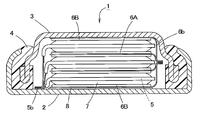
- FIG. 1 is a longitudinal sectional view schematically showing an example of a flat nonaqueous secondary battery according to an embodiment of the present invention.
- FIG. 2 is a partially enlarged cross-sectional view of FIG.
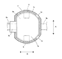
- FIG. 3 is a plan view schematically showing an example of the positive electrode of the flat nonaqueous secondary battery according to the embodiment of the present invention.
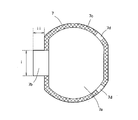
- FIG. 4 is a plan view schematically illustrating an example of a separator of a flat nonaqueous secondary battery according to an embodiment of the present invention.
- FIG. 5 is a plan view of a separator used in the flat nonaqueous secondary battery of the example.
- FIG. 1 is a longitudinal sectional view showing a battery case (an outer case 2 and a sealing case 3) and an insulating gasket 4 of a flat non-aqueous secondary battery 1 (hereinafter also simply referred to as a battery).
- FIG. 2 is an enlarged view of a part of FIG. 1 and a sectional view of the electrode group.
- the flat non-aqueous secondary battery 1 includes a positive electrode 5 and a negative electrode 6 in a space (sealed space) formed by an outer case 2, a sealing case 3, and an insulating gasket 4.
- a stacked electrode group and a nonaqueous electrolyte solution (not shown) that are stacked so that their planes are substantially parallel (including parallel) to the flat surface (upper and lower surfaces in FIG. 1) of the battery 1 are accommodated. It is constituted by being done.
- the sealing case 3 is fitted into the opening of the outer case 2 with the insulating gasket 4 sandwiched between the sealing case 3 and the outer case 2.
- the opening end of the outer case 2 is bent so as to be deformed inward of the battery.
- the insulating gasket 4 is sandwiched between the sealing case 3 and the outer case 2, so that the opening of the outer case 2 is sealed and a sealed space is formed inside the battery.
- the outer case 2 and the sealing case 3 are made of a metal material such as stainless steel.
- the insulating gasket 4 is made of an insulating resin such as nylon.
- the positive electrode 5 includes a plate-like current collector 52 and a positive electrode mixture layer 51 formed on one or both surfaces of the current collector 52 as shown in FIGS. 1 and 2.
- FIG. 3 schematically shows a plan view of the positive electrode 5.
- the positive electrode 5 has a main body portion 5a (positive electrode main body portion) and a current collecting tab portion that protrudes from the main body portion 5a in plan view and has a narrower width (length in the vertical direction in FIG. 3) than the main body portion 5a. 5b (positive electrode current collecting tab part).
- the main body 5 a of the positive electrode 5 is configured by forming a positive electrode mixture layer 51 on one or both surfaces of a current collector 52 as shown in FIG. On the other hand, in the current collecting tab portion 5b of the positive electrode 5, the positive electrode mixture layer 51 is not formed on the surface of the current collector 52, and the current collector 52 is exposed.
- the negative electrode 6 includes a plate-like current collector 62 and a negative electrode agent layer 61 formed on one side or both sides of the current collector 62.
- the negative electrode 6 also has a main body portion 6 a and a current collecting tab portion 6 b that protrudes from the main body portion 6 a in a plan view and is narrower than the main body portion 6 a.
- the negative electrode in which the negative electrode layer 61 is formed on both sides of the current collector 62 is represented as a negative electrode 6A
- the negative electrode in which the negative electrode layer 61 is formed on only one side of the current collector 62 is This is represented as a negative electrode 6B (see FIG. 1).
- the main body 6 a of the negative electrode 6 is configured by forming a negative electrode agent layer 61 on one or both surfaces of the current collector 62.
- the negative electrode agent layer 61 is not formed on the surface of the current collector 62, and the current collector 62 is exposed.
- the upper and lower ends of the electrode group are negative electrodes 6B and 6B.
- These negative electrodes 6B and 6B are arranged in the battery so that the negative electrode agent layer 61 is located on the surface of the current collector 62 on the inner side of the battery.
- the exposed surface of the current collector 62 of the negative electrode 6B located on the upper side in FIG. 1 is welded to or in contact with the inner surface of the sealing case 3, so that the sealing case 3 and the negative electrode 6B are connected to each other. Electrically connected. That is, in the flat nonaqueous secondary battery 1 of the present embodiment, the sealing case 3 also serves as the negative electrode terminal.
- the negative electrode 6 (the negative electrode 6A in which the negative electrode agent layer 61 is formed on both surfaces of the current collector 62 and the negative electrode 6B in which the negative electrode agent layer 61 is formed on only one surface of the current collector 62).
- the current collecting tab portion 6b is electrically connected to each other.
- the current collection tab part 6b of each negative electrode 6 is mutually connected by welding, for example.
- the positive electrode 5 has the current collecting tab portions 5b electrically connected to each other.
- the current collecting tab portions 5b connected to each other are welded to or in contact with the inner surface of the outer case 2 so that the outer case 2 and the positive electrode 5 are electrically connected. That is, in the flat nonaqueous secondary battery 1 of the present embodiment, the outer case 2 also serves as a positive electrode terminal.
- An insulating seal 8 made of polyethylene terephthalate (PET), polyimide, or the like is provided between the negative electrode 6B located at the bottom of the electrode group and the outer case 2 that also serves as a positive electrode terminal for the purpose of insulating the two. Has been placed.
- FIG. 4 schematically shows a plan view of the separator 7. 4 assumes a case of a stacked electrode group in which the positive electrode 5 and the negative electrode 6 covered with the separator 7 are stacked, and the positive electrode 5 covered with the separator 7 is indicated by a dotted line.
- a current collecting tab portion 6b of the negative electrode 6 disposed on the lower side is indicated by a one-dot chain line.
- the binding tape 9 for suppressing the positional shift of each component of an electrode group is shown with the dashed-two dotted line.
- the negative electrode since the negative electrode is disposed so as to sandwich the positive electrode 5, in the state illustrated in FIG. 4, the negative electrode is also disposed above the separator 7 (frontward in the figure).
- the separator 7 is welded to the other separator 7 disposed on the opposite side of the positive electrode 5 (indicated by a dotted line in the figure) at the peripheral edge.
- the two separators 7 form a bag-shaped member that can accommodate the positive electrode 5 therein. That is, as shown in FIG. 4, the two separators 7 sandwiching the positive electrode 5 are welded to each other at the respective peripheral portions, thereby joining the joints 7 c (parts with lattice hatching in FIG. 4). ) Is formed.
- Each separator 7 includes a main body portion 7a that covers the entire surface of the main body portion 5a of the positive electrode 5, and an overhang portion 7b that protrudes from the main body portion 7a so as to cover a boundary portion between the current collecting tab portion 5b of the positive electrode 5 and the main body portion 5a. have.
- the main body part 7a has a larger area than the main body part 5a so as to cover the main body part 5a of the positive electrode 5 in plan view. At least a part of the peripheral portion of the main body portion 7a constitutes the above-described joint portion 7c.
- the separator 7 has a heat shrinkage ratio Ca at 100 ° C. in an arbitrary direction A of 1 to 20%, and a heat shrinkage ratio at 100 ° C. in a direction B perpendicular to the direction A is Cb (%). It is constituted by a microporous film made of a thermoplastic resin having a ratio Ca / Cb between the heat shrinkage ratio Ca and the heat shrinkage ratio Cb of 1.5 or more, preferably 2 or more. Note that the thermal shrinkage Cb of the microporous film constituting the separator is preferably 0% to 10%.
- thermal shrinkage (%) 100 x (dimension before throwing-dimension after throwing) / (dimension before throwing)
- the microporous membrane is usually produced through a stretching process. Therefore, generally, the distortion in the manufacturing direction (MD direction) is larger than that in the direction orthogonal to the manufacturing direction (TD direction). Therefore, in such a microporous film, the thermal shrinkage rate is anisotropic, and the thermal shrinkage rate in the direction corresponding to the MD direction is large, while the thermal shrinkage rate is small in the TD direction. That is, usually, the direction A in the microporous film corresponds to the MD direction, and the direction B corresponds to the TD direction.
- the direction A in the microporous membrane constituting the separator 7 is indicated by a dotted arrow, and the direction B is indicated by a solid arrow.
- the separators 7 existing on both surfaces of the positive electrode 5 are arranged such that the direction B is in the direction in which the projecting portion 7b protrudes from the main portion 7a (lateral direction in FIG. 4). It is formed to be substantially parallel (including parallel, the same applies hereinafter). That is, the direction B is substantially parallel to the direction in which the current collecting tab portion 5b of the positive electrode 5 protrudes from the main body portion 5a.
- the present embodiment as shown in FIG.
- the direction in which the protruding portion 7 b projects from the main body portion 7 a in the separator 7 coincides with the direction in which the current collecting tab portion 5 b projects from the main body portion 5 a in the positive electrode 5.
- the protruding tab 7b of the separator 7 can cover the current collecting tab portion 5b of the positive electrode 5, the protruding direction of the protruding portion 7b may be different from the protruding direction of the collecting tab portion 5b. Good.
- the current collecting tab of the positive electrode 5 among the peripheral portions of the protruding portions 7 b in the two separators 7 arranged on both surfaces of the positive electrode 5.
- a joint portion cannot be provided in a portion where the portion 5b protrudes. Therefore, for example, when the direction in which the thermal contraction rate of the separator 7 is large (the direction A) is substantially parallel to the direction in which the current collecting tab portion 5b of the positive electrode 5 protrudes from the main body portion 5a, When the temperature becomes high, large shrinkage occurs in the overhanging portion 7b.
- the overhanging portion is also obtained when the temperature inside the battery becomes high. Shrinkage at 7b is suppressed. Therefore, contact between the current collecting tab portion 5b of the positive electrode 5 and the negative electrode 6 can be prevented, and occurrence of a short circuit can be suppressed.
- the direction A that is more likely to be thermally contracted is indicated by a dotted arrow in FIG. It becomes the direction shown by.
- shrinkage at a high temperature is suppressed by the joint 7 c formed at the peripheral edge of the separator 7.
- the flat non-aqueous secondary battery 1 of the present embodiment can ensure good safety even at high temperatures by adopting the above configuration.
- the peripheral portions of the two separators 7 are welded together to form the joint 7c.
- a layer made of a resin is interposed between the separators 7, and this layer and the two separators 7 are welded, or both sides of this layer are bonded.
- a method of applying an adhesive or the like and bonding the two separators 7 is conceivable. In this way, when another layer is interposed between the two separators, the strength of the joint portion tends to be smaller than the other portions of the separator 7. For this reason, for example, when the inside of the battery becomes high temperature and the separator 7 contracts, there is a possibility that the joint portion peels and the positive electrode and the negative electrode are in direct contact with each other.
- the peripheral portions of the two separators are directly welded to each other, so that the strength of the joint 7c is substantially equal to the strength of the separator itself. It becomes. Therefore, even if the temperature in the battery becomes a high temperature at which the separator can shrink, the peeling of the joint portion 7c is suppressed. Therefore, since the contact between the positive electrode and the negative electrode is prevented, the battery is highly safe.
- the positive electrode 5 is stacked on one separator 7 and further on it. After the separators 7 are stacked, a method of welding the peripheral portions of these separators 7 can be employed. It is also possible to employ a method in which two separators 7 are stacked, the peripheral portions thereof are welded to join the separators 7 together, and then the positive electrode 5 is inserted between the separators 7.
- peripheral parts in the main part 7a of the separator 7 may be the joint part 7c, for example, as shown in FIG. 4, a part of the peripheral part is not welded so as not to weld the separators 7 to each other. You may leave as part 7d and 7d (non-joining part).
- part 7d and 7d non-joining part
- two separators 7 are welded to form a bag and the positive electrode 5 is accommodated therein, or the positive electrode 5 is disposed on one separator 7 and another separator 7 is disposed on the positive electrode 5.
- the peripheral edge portion of the separator 7 is welded to form a bag shape in a state in which air is disposed, air may remain in the bag-shaped member formed by the separator 7.
- the separator 7 is pressed between the positive electrode 5 and the negative electrode 6 when the exterior case 2 and the sealing case 3 are caulked by providing the non-welded portion 7d described above, Residual air is discharged well out of the separator 7 through the non-welded portions 7d and 7d. Therefore, it is possible to prevent the occurrence of problems due to residual air in the separator (for example, problems such as non-uniform reaction during power generation and reduced capacity).
- the number of the non-welded portions 7d is preferably about 1 to 5 from the viewpoint of suppressing a decrease in the productivity of the battery 1.
- the length of the outer edge of the non-welded portion 7d in the main body portion 7a of the separator 7 is equal to the total length of the outer edge of the main body portion 7a of the separator 7 About 15% to 60% of the total length).
- 40% or more (preferably 70% or more) of the entire length of the outer edge is a joint portion.
- the peripheral edge of the separator 7 can be welded by, for example, a hot press.
- the heating temperature may be higher than the melting point of the thermoplastic resin constituting the separator 7.
- it is preferably performed at a temperature higher by 10 ° C. to 50 ° C. than the melting point of the thermoplastic resin.
- the heating press time is not particularly limited as long as a good joint can be formed, but is preferably about 1 to 10 seconds.
- the electrodes at the upper and lower ends (the outermost two electrodes) of the electrode group are both negative electrodes 6, but not limited to this, the electrodes at the upper and lower ends of the electrode group (the two outermost electrodes) One or both of them may be the positive electrode 5.
- the positive electrode 5 is attached to both surfaces of the current collector 52.
- the positive electrode mixture layer 51 may be provided, and the current collecting tab portion 5b may be in contact with a battery case (for example, the outer case 2) that also serves as a positive electrode terminal.
- the electrical power collector 52 has the positive mix layer 51 only in the single side
- both the upper and lower electrodes (two outermost electrodes) in the electrode group are the positive electrodes 5
- the current collecting tab portions 6b of the respective negative electrodes 6 are electrically connected to each other, and the current collecting tabs are connected.
- the battery case and the negative electrode 6 can be electrically connected by welding or contacting the portion 6b with the inner surface of a battery case (for example, the sealing case 3) that also serves as the negative electrode terminal.
- separators are arranged on both sides of the positive electrode whose both sides are opposed to the negative electrode.
- the separator does not have to be arranged on both surfaces, and the separator is provided only on the surface facing the negative electrode. May be arranged.
- a polyethylene terephthalate between the battery case serving also as the negative electrode terminal and the positive electrode 5 ( An insulator such as an insulating seal made of PET) or polyimide is disposed.
- the electrical connection between the current collecting tab portion 5b of each positive electrode 5 and the battery case also serving as the positive electrode terminal, and the electrical connection between the current collecting tab portion 6b of each negative electrode 6 and the battery case serving also as the negative electrode terminal are positive electrodes.
- 5 and the negative electrode 6 may be realized by a separate lead body (lead body made of metal foil or the like).
- the positive electrode mixture layer 51 of the positive electrode 5 is a layer containing a positive electrode active material, a conductive additive, a binder, and the like.
- M is at least one metal element selected from the group consisting of Mg, Mn, Fe, Co, Ni, Cu, Zn, Al and Cr, and 0 ⁇ x ⁇ 1.1, 0 ⁇ y ⁇ 1.0, and 2.0 ⁇ z ⁇ 2.2.
- These positive electrode active materials may be used individually by 1 type, and may use 2 or more types together.
- examples of the conductive assistant for the positive electrode 5 include carbon black, flaky graphite, ketjen black, acetylene black, and fibrous carbon.
- examples of the binder of the positive electrode 5 include polytetrafluoroethylene (PTFE), polyvinylidene fluoride (PVDF), carboxymethyl cellulose, and styrene butadiene rubber.
- the positive electrode 5 is prepared by dispersing a positive electrode mixture obtained by mixing a positive electrode active material, a conductive additive, and a binder in water or an organic solvent to prepare a positive electrode mixture-containing paste. It is manufactured by applying to one or both sides of a current collector 52 made of metal foil, expanded metal, plain weave wire mesh, etc., drying, and then pressure forming.
- a positive electrode mixture-containing paste may be prepared by dissolving or dispersing a binder in water or a solvent in advance and mixing it with a positive electrode active material or the like.
- the manufacturing method of the positive electrode 5 is not limited to the above-described method, and other methods may be used.
- the composition of the positive electrode 5 is, for example, 75% by mass to 90% by mass of the positive electrode active material, 5% by mass to 20% by mass of the conductive assistant, and 3% by mass of the binder in 100% by mass of the positive electrode mixture constituting the positive electrode 5. % To 15% by mass is preferable.
- the thickness of the positive electrode mixture layer 51 is preferably 30 ⁇ m to 200 ⁇ m, for example.
- the material of the current collector 52 of the positive electrode 5 of the positive electrode 5 aluminum or an aluminum alloy is preferable.
- the opposing area between the positive electrode mixture layer 51 and the negative electrode agent layer 61 is increased and the load of the battery 1 is increased.
- the thickness of the current collector 52 is preferably, for example, 8 ⁇ m to 20 ⁇ m.
- the negative electrode 6 used in the present embodiment includes a configuration in which the active material includes lithium, a lithium alloy, a carbon material capable of occluding and releasing lithium ions, lithium titanate, and the like.
- the lithium content is preferably 1 atomic% to 15 atomic%, for example.
- the carbon material that can be used for the negative electrode active material include artificial graphite, natural graphite, low crystalline carbon, coke, and anthracite.
- the lithium titanate represented by the general formula Li x Ti y O 4 can be obtained, for example, by heat treating titanium oxide and a lithium compound at 760 ° C. to 1100 ° C. As the titanium oxide, either anatase type or rutile type can be used, and examples of the lithium compound include lithium hydroxide, lithium carbonate, and lithium oxide.
- the negative electrode active material is lithium or a lithium alloy
- the negative electrode 6 is made by pressure bonding lithium or a lithium alloy to a current collector 62 such as a metal net, and the negative electrode made of lithium, a lithium alloy, or the like on the surface of the current collector 62 It is obtained by forming the agent layer 61.
- a carbon material or lithium titanate is used as the negative electrode active material, for example, a negative electrode composite obtained by mixing a carbon material or lithium titanate with a binder as the negative electrode active material and, if necessary, a conductive additive.
- a negative electrode mixture-containing paste is prepared by dispersing the agent in water or an organic solvent.
- a negative electrode mixture-containing paste may be prepared by dissolving or dispersing a binder in water or a solvent in advance and mixing it with a negative electrode active material or the like.
- the manufacturing method of the negative electrode 6 is not limited to the above-described method, and other methods may be used.
- a binder and conductive support agent of a negative electrode the various binders and conductive support agents which were illustrated previously as what can be used for a positive electrode can be used.
- the composition of the negative electrode 6 when a carbon material is used as the negative electrode active material is, for example, 80% by mass to 95% by mass of the carbon material and 3% by mass to 15% of the binder in 100% by mass of the negative electrode mixture constituting the negative electrode 6. It is preferable to set it as the mass%.
- the conductive auxiliary is preferably 5% by mass to 20% by mass.
- the composition of the negative electrode 6 when lithium titanate is used as the negative electrode active material is, for example, 75% to 90% by mass of lithium titanate and 3% of binder in 100% by mass of the negative electrode mixture constituting the negative electrode 6. It is preferable to set the mass to 15% by mass.
- the conductive auxiliary is preferably 5% by mass to 20% by mass.
- the thickness of the negative electrode agent layer 61 in the negative electrode 6 is preferably 40 ⁇ m to 200 ⁇ m, for example.
- the material of the current collector 62 of the negative electrode 6 of the negative electrode 6 copper or a copper alloy is preferable.
- the opposing area of the positive electrode mixture layer 51 and the negative electrode agent layer 61 is increased by increasing the number of stacked positive electrodes 5 and negative electrodes 6 in the battery 1 while reducing the thickness of the entire negative electrode 6. From the viewpoint of improving load characteristics, it is preferable to use a metal foil for the current collector 62.
- the thickness of the current collector 62 is preferably, for example, 5 ⁇ m to 30 ⁇ m.
- thermoplastic resin constituting the separator 7 for example, polyolefins such as polyethylene (PE), polypropylene (PP), ethylene-propylene copolymer, and polymethylpentene are preferable. From the viewpoint of welding the separators 7 together, or arranging and welding the same type of resin as that constituting the separators 7 between the separators 7, the differential scanning according to the provisions of JIS K 7121 More preferred is a polyolefin having a melting temperature of 100 ° C. to 180 ° C. measured using a calorimeter (DSC).
- DSC calorimeter
- thermoplastic resin microporous film constituting the separator 7 may be any form as long as it has an ionic conductivity sufficient to obtain necessary battery characteristics.
- an ion-permeable microporous film (a microporous film that is widely used as a battery separator) that is formed by a conventionally known dry or wet stretching method or the like and has a large number of pores is preferable.
- the thickness of the separator 7 is preferably 5 ⁇ m to 25 ⁇ m, for example.
- the porosity is preferably 30% to 70%, for example.
- the positive electrode 5, the negative electrode 6, and the separator 7 are arranged such that the current collecting tab portions 5b of the respective positive electrodes 5 face the same direction in a plan view of the electrode group, and
- the current collecting tab portion 6b of each negative electrode 6 is preferably arranged so as to face the same direction in a plan view of the electrode group.
- the electric tab portion 5b and the current collecting tab portion 6b are arranged at positions facing each other in plan view.
- the electrode group composed of the positive electrode 5, the negative electrode 6 and the separator 7 is preferably bound around the outer periphery with a binding tape 9 made of polypropylene having chemical resistance. Thereby, position shift of each component (the positive electrode 5 covered with the separator 7 and the negative electrode 6) can be suppressed.
- the total number of layers of the electrode is at least 4, but it is also possible to have a larger number of layers (5 layers, 6 layers, 7 layers, 8 layers, etc.). However, if the number of stacked positive electrodes 5 and negative electrodes 6 is increased too much, the merit as a flat battery may be reduced. Therefore, it is usually preferable to use 40 layers or less.
- non-aqueous electrolyte examples include cyclic carbonates such as ethylene carbonate (EC), propylene carbonate, butylene carbonate, and vinylene carbonate; chain carbonates such as dimethyl carbonate, diethyl carbonate (DEC), and methyl ethyl carbonate; Ethers such as 2-dimethoxyethane, diglyme (diethylene glycol methyl ether), triglyme (triethylene glycol dimethyl ether), tetraglyme (tetraethylene glycol dimethyl ether), 1,2-dimethoxyethane, 1,2-diethoxymethane, tetrahydrofuran; An electrolytic solution prepared by dissolving an electrolyte (lithium salt) in an organic solvent at a concentration of about 0.3 mol / L to 2.0 mol / L is used. Rukoto can.
- the said organic solvent may be used individually by 1 type, respectively, and may use 2 or more types together.
- electrolyte examples include LiBF 4 , LiPF 6 , LiAsF 6 , LiSbF 6 , LiClO 4 , LiCF 3 SO 3 , LiC 4 F 9 SO 3 , LiN (CF 3 SO 2 ) 2 , LiN (C 2 F 5 SO 2 ) Lithium salts such as 2 are mentioned.
- the planar shape of the flat non-aqueous secondary battery 1 is not particularly limited, and may be a polygonal shape such as a square (for example, a quadrangle) in addition to a circular shape that is the mainstream of conventionally known flat batteries.
- the polygon such as a square as the planar shape of the battery 1 in this specification includes a shape in which the corner is cut off and a shape in which the corner is curved.
- the planar shape of the main body portions 5 a and 6 a of the positive electrode 5 and the negative electrode 6 may be a shape corresponding to the planar shape of the battery 1.
- the main body portions 5a and 6a may be polygons including rectangles such as rectangles and squares in addition to substantially circular shapes.
- the portion where the current collecting tab portion of the counter electrode is disposed is shown in FIG. 3 in order to prevent contact with the current collecting tab portion of the counter electrode.
- the present invention is not limited to this, and the outer case 2 is a negative electrode case and a sealing case as necessary. 3 may be a positive electrode case.
- the two separators 7 are joined at the peripheral edge of the main body 7a, but one separator may be folded and joined.
- the flat non-aqueous secondary battery 1 can be applied to the same use as a conventionally known flat non-aqueous secondary battery.
- Example 1 Preparation of positive electrode> A positive electrode was prepared using LiCoO 2 as a positive electrode active material, carbon black as a conductive additive, and PVDF as a binder. First, LiCoO 2 : 93 parts by weight and carbon black: 3 parts by weight were mixed, and the resulting mixture and PVDF: 4 parts by weight were previously dissolved in N-methyl-2-pyrrolidone (NMP). The paste was mixed with the solution to prepare a positive electrode mixture-containing paste. Here, each said weight part is a value when a positive electrode mixture is 100 weight part. And the positive mix containing paste obtained as mentioned above was apply
- NMP N-methyl-2-pyrrolidone
- the positive mix containing paste when apply
- the strip-shaped positive electrode has the shape shown in FIG. 3 so that the positive electrode mixture layer forming portion is a main body portion (arc portion diameter 15.1 mm) and the positive electrode mixture layer non-forming portion is a current collecting tab portion.
- the battery positive electrode was obtained.
- the separator 7 is disposed on both surfaces of the battery positive electrode, and the portion (7c) shown in FIG. 4 is welded by a hot press (temperature 170 ° C., press time 2 seconds).
- the joining portion 7c was formed at a part of the peripheral edge portion of the main body portion 7a in the two separators 7, and the battery positive electrode and the separator 7 were integrated.
- variety of the junction part in the two separators 7 was 0.3 mm. Of the outer edges of the main body portion 7a of the two separators 7, 90% of the total length was defined as the joint portion 7c.
- a negative electrode was prepared using graphite as the negative electrode active material and PVDF as the binder.
- the graphite: 94 parts by weight, PVDF: 6 parts by weight, and a binder solution previously dissolved in NMP were mixed to prepare a negative electrode mixture-containing paste.
- each said weight part is a value when a negative electrode mixture is 100 weight part.
- the negative mix containing paste obtained as mentioned above was apply
- the portion where the coated portion is the front surface is the back surface
- the applied negative electrode mixture-containing paste was dried to form a negative electrode mixture layer, and then roll-pressed and cut into a predetermined size to obtain a strip-shaped negative electrode.
- the negative electrode was formed so that the width was 40 mm and the thickness of the negative electrode mixture layer forming part was 190 ⁇ m when formed on both sides of the current collector, and 100 ⁇ m when formed on one side of the current collector. .
- the strip-shaped negative electrode has the same shape as the positive electrode, with the negative electrode mixture layer forming part being the main body part (arc portion diameter 16.3 mm) and the negative electrode mixture layer non-forming part being the current collecting tab part. Punched out.
- a negative electrode for a battery having a negative electrode mixture layer on one side of the current collector and a negative electrode for a battery having negative electrode mixture layers on both sides of the current collector were obtained.
- a part of the negative electrode for a battery having the negative electrode mixture layer on one side of the current collector was punched after a PET film having a thickness of 100 ⁇ m was attached to the exposed surface of the current collector of the strip-shaped negative electrode. .
- An electrode group was configured using two negative electrodes (one of which was a PET film attached to the exposed surface of the current collector). Specifically, the battery positive electrode and the battery negative electrode were alternately stacked so that the battery negative electrode having the negative electrode mixture layer formed on one side of the current collector was positioned on the outermost part. And the current collection tab part of each battery positive electrode was welded collectively, and the electrode collection was formed by welding the current collection tab part of each battery negative electrode collectively.
- the electrode group was placed in the outer case so that the PET film faced the inner surface of the outer case, and the collected current collecting tab portion of the positive electrode was welded to the inner surface of the outer case.
- an insulating gasket is attached to the sealing case, and a non-aqueous electrolyte (ethylene carbonate and methyl ethyl carbonate in a mixed solvent having a volume ratio of 1: 2 and LiPF 6 at a concentration of 1.2 mol / l is placed in the sealing case. After 200 mg of the dissolved solution) is put, an outer case containing the electrode group is put on.
- the flat non-aqueous secondary battery is designed to discharge at a current value of 14 mA and a discharge capacity of 70 mAh.
- Comparative Example 2 The same PE microporous membrane separator as in Example 1 has the shape shown in FIGS. 4 and 5 (the length of i in FIG. 5 is 5 mm and the length of ii is 0.8 mm), and the direction A is A flat non-aqueous secondary battery similar to that of Example 1 was produced except that the overhanging part was cut out so as to be parallel to the direction protruding from the main part.
- the external short circuit test was conducted on each of the 10 flat non-aqueous secondary batteries of Examples 1 and 2 and Comparative Examples 1 and 2.
- each battery was externally short-circuited at a resistance of 100 m ⁇ for 15 minutes in an environment of 24 ° C., and then the open circuit voltage of each battery was measured after 24 hours. Batteries with an open circuit voltage of 0 V were used as internal short-circuit products, and the number of generated batteries was examined. These results are shown in Table 1.
- the flat non-aqueous secondary batteries of Examples 1 and 2 in which separators are appropriately arranged have good occurrence of internal short circuit even when the temperature in the battery rises due to the external short circuit test. It is suppressed. Therefore, the flat nonaqueous secondary batteries of Examples 1 and 2 have higher safety than the batteries of Comparative Examples 1 and 2 in which the characteristics of the separators themselves used and the arrangement of the separators are not appropriate.
- the flat nonaqueous secondary batteries of Examples 1 and 2 were disassembled after the external short circuit test. In these batteries, no shrinkage was observed at the protruding portion of the separator, and no separation of the joint between the separators occurred.
Landscapes
- Chemical & Material Sciences (AREA)
- Chemical Kinetics & Catalysis (AREA)
- Electrochemistry (AREA)
- General Chemical & Material Sciences (AREA)
- Engineering & Computer Science (AREA)
- Materials Engineering (AREA)
- Manufacturing & Machinery (AREA)
- Secondary Cells (AREA)
- Connection Of Batteries Or Terminals (AREA)
- Battery Electrode And Active Subsutance (AREA)
- Cell Separators (AREA)
Applications Claiming Priority (2)
| Application Number | Priority Date | Filing Date | Title |
|---|---|---|---|
| JP2009269417A JP5566671B2 (ja) | 2009-11-27 | 2009-11-27 | 扁平形非水二次電池 |
| JP2009-269417 | 2009-11-27 |
Publications (1)
| Publication Number | Publication Date |
|---|---|
| WO2011065344A1 true WO2011065344A1 (ja) | 2011-06-03 |
Family
ID=44066449
Family Applications (1)
| Application Number | Title | Priority Date | Filing Date |
|---|---|---|---|
| PCT/JP2010/070855 Ceased WO2011065344A1 (ja) | 2009-11-27 | 2010-11-24 | 扁平形非水二次電池 |
Country Status (2)
| Country | Link |
|---|---|
| JP (1) | JP5566671B2 (enExample) |
| WO (1) | WO2011065344A1 (enExample) |
Cited By (2)
| Publication number | Priority date | Publication date | Assignee | Title |
|---|---|---|---|---|
| JP2017027770A (ja) * | 2015-07-22 | 2017-02-02 | トヨタ自動車株式会社 | 全固体二次電池の検査方法、及びその検査方法を利用した全固体二次電池の製造方法 |
| CN118920026A (zh) * | 2024-09-30 | 2024-11-08 | 宁德时代新能源科技股份有限公司 | 电池单体、电池装置和用电装置 |
Families Citing this family (1)
| Publication number | Priority date | Publication date | Assignee | Title |
|---|---|---|---|---|
| JP6079856B2 (ja) * | 2015-11-18 | 2017-02-15 | 株式会社豊田自動織機 | 蓄電装置 |
Citations (6)
| Publication number | Priority date | Publication date | Assignee | Title |
|---|---|---|---|---|
| WO2003063269A1 (en) * | 2002-01-24 | 2003-07-31 | Hitachi Maxell, Ltd. | Nonaqueous secondary cell and electronic device incorporating same |
| JP2009084300A (ja) * | 2007-08-31 | 2009-04-23 | Tonen Chem Corp | ポリオレフィン微多孔膜、電池用セパレータ及び電池 |
| JP2009224276A (ja) * | 2008-03-18 | 2009-10-01 | Hitachi Maxell Ltd | 扁平角型電池 |
| JP2009231281A (ja) * | 2008-02-28 | 2009-10-08 | Teijin Ltd | 非水電解質電池セパレータ及び非水電解質二次電池 |
| JP2009242631A (ja) * | 2008-03-31 | 2009-10-22 | Asahi Kasei E-Materials Corp | ポリオレフィン微多孔膜 |
| JP2010212206A (ja) * | 2009-03-12 | 2010-09-24 | Hitachi Maxell Ltd | 扁平形二次電池 |
Family Cites Families (1)
| Publication number | Priority date | Publication date | Assignee | Title |
|---|---|---|---|---|
| JP2009138159A (ja) * | 2007-12-10 | 2009-06-25 | Asahi Kasei Chemicals Corp | 微多孔膜 |
-
2009
- 2009-11-27 JP JP2009269417A patent/JP5566671B2/ja active Active
-
2010
- 2010-11-24 WO PCT/JP2010/070855 patent/WO2011065344A1/ja not_active Ceased
Patent Citations (6)
| Publication number | Priority date | Publication date | Assignee | Title |
|---|---|---|---|---|
| WO2003063269A1 (en) * | 2002-01-24 | 2003-07-31 | Hitachi Maxell, Ltd. | Nonaqueous secondary cell and electronic device incorporating same |
| JP2009084300A (ja) * | 2007-08-31 | 2009-04-23 | Tonen Chem Corp | ポリオレフィン微多孔膜、電池用セパレータ及び電池 |
| JP2009231281A (ja) * | 2008-02-28 | 2009-10-08 | Teijin Ltd | 非水電解質電池セパレータ及び非水電解質二次電池 |
| JP2009224276A (ja) * | 2008-03-18 | 2009-10-01 | Hitachi Maxell Ltd | 扁平角型電池 |
| JP2009242631A (ja) * | 2008-03-31 | 2009-10-22 | Asahi Kasei E-Materials Corp | ポリオレフィン微多孔膜 |
| JP2010212206A (ja) * | 2009-03-12 | 2010-09-24 | Hitachi Maxell Ltd | 扁平形二次電池 |
Cited By (2)
| Publication number | Priority date | Publication date | Assignee | Title |
|---|---|---|---|---|
| JP2017027770A (ja) * | 2015-07-22 | 2017-02-02 | トヨタ自動車株式会社 | 全固体二次電池の検査方法、及びその検査方法を利用した全固体二次電池の製造方法 |
| CN118920026A (zh) * | 2024-09-30 | 2024-11-08 | 宁德时代新能源科技股份有限公司 | 电池单体、电池装置和用电装置 |
Also Published As
| Publication number | Publication date |
|---|---|
| JP2011113826A (ja) | 2011-06-09 |
| JP5566671B2 (ja) | 2014-08-06 |
Similar Documents
| Publication | Publication Date | Title |
|---|---|---|
| CN104916793B (zh) | 扁平形非水二次电池 | |
| JP6032628B2 (ja) | 薄型電池 | |
| JP5348720B2 (ja) | 扁平形非水二次電池 | |
| JPWO2012124188A1 (ja) | 非水二次電池用電極、その製造方法、および非水二次電池 | |
| JP6081745B2 (ja) | 扁平形非水二次電池 | |
| JP2011159491A (ja) | 扁平形非水二次電池 | |
| JP5483587B2 (ja) | 電池およびその製造方法 | |
| JP2012064366A (ja) | 扁平形非水二次電池およびその製造方法 | |
| JP2014049371A (ja) | 扁平形非水二次電池およびその製造方法 | |
| JP5495270B2 (ja) | 電池 | |
| JP5562655B2 (ja) | 扁平形非水二次電池 | |
| JP6178183B2 (ja) | 非水電解質電池、組電池及び蓄電池装置 | |
| JP5377249B2 (ja) | 扁平形非水二次電池 | |
| JP5528305B2 (ja) | 扁平形非水二次電池 | |
| JP5562654B2 (ja) | 扁平形非水二次電池 | |
| JP5566671B2 (ja) | 扁平形非水二次電池 | |
| JP5528304B2 (ja) | 扁平形非水二次電池 | |
| JP2011129330A (ja) | 扁平形非水二次電池 | |
| JP2011154784A (ja) | 扁平形非水二次電池 | |
| JP6240265B2 (ja) | 扁平形非水二次電池の製造方法 | |
| JP5681358B2 (ja) | 扁平形非水二次電池 | |
| JP5473063B2 (ja) | 扁平形非水二次電池およびその製造方法 | |
| JP5377250B2 (ja) | 扁平形非水二次電池 | |
| JP2011187392A (ja) | 扁平形非水二次電池 |
Legal Events
| Date | Code | Title | Description |
|---|---|---|---|
| 121 | Ep: the epo has been informed by wipo that ep was designated in this application |
Ref document number: 10833190 Country of ref document: EP Kind code of ref document: A1 |
|
| NENP | Non-entry into the national phase |
Ref country code: DE |
|
| 122 | Ep: pct application non-entry in european phase |
Ref document number: 10833190 Country of ref document: EP Kind code of ref document: A1 |