WO2011065344A1 - 扁平形非水二次電池 - Google Patents
扁平形非水二次電池 Download PDFInfo
- Publication number
- WO2011065344A1 WO2011065344A1 PCT/JP2010/070855 JP2010070855W WO2011065344A1 WO 2011065344 A1 WO2011065344 A1 WO 2011065344A1 JP 2010070855 W JP2010070855 W JP 2010070855W WO 2011065344 A1 WO2011065344 A1 WO 2011065344A1
- Authority
- WO
- WIPO (PCT)
- Prior art keywords
- positive electrode
- main body
- separator
- negative electrode
- secondary battery
- Prior art date
Links
Images


Classifications
-
- H—ELECTRICITY
- H01—ELECTRIC ELEMENTS
- H01M—PROCESSES OR MEANS, e.g. BATTERIES, FOR THE DIRECT CONVERSION OF CHEMICAL ENERGY INTO ELECTRICAL ENERGY
- H01M4/00—Electrodes
- H01M4/02—Electrodes composed of, or comprising, active material
- H01M4/13—Electrodes for accumulators with non-aqueous electrolyte, e.g. for lithium-accumulators; Processes of manufacture thereof
-
- H—ELECTRICITY
- H01—ELECTRIC ELEMENTS
- H01M—PROCESSES OR MEANS, e.g. BATTERIES, FOR THE DIRECT CONVERSION OF CHEMICAL ENERGY INTO ELECTRICAL ENERGY
- H01M50/00—Constructional details or processes of manufacture of the non-active parts of electrochemical cells other than fuel cells, e.g. hybrid cells
- H01M50/40—Separators; Membranes; Diaphragms; Spacing elements inside cells
- H01M50/489—Separators, membranes, diaphragms or spacing elements inside the cells, characterised by their physical properties, e.g. swelling degree, hydrophilicity or shut down properties
-
- H—ELECTRICITY
- H01—ELECTRIC ELEMENTS
- H01M—PROCESSES OR MEANS, e.g. BATTERIES, FOR THE DIRECT CONVERSION OF CHEMICAL ENERGY INTO ELECTRICAL ENERGY
- H01M10/00—Secondary cells; Manufacture thereof
- H01M10/04—Construction or manufacture in general
- H01M10/0422—Cells or battery with cylindrical casing
- H01M10/0427—Button cells
-
- H—ELECTRICITY
- H01—ELECTRIC ELEMENTS
- H01M—PROCESSES OR MEANS, e.g. BATTERIES, FOR THE DIRECT CONVERSION OF CHEMICAL ENERGY INTO ELECTRICAL ENERGY
- H01M50/00—Constructional details or processes of manufacture of the non-active parts of electrochemical cells other than fuel cells, e.g. hybrid cells
- H01M50/40—Separators; Membranes; Diaphragms; Spacing elements inside cells
- H01M50/409—Separators, membranes or diaphragms characterised by the material
- H01M50/411—Organic material
- H01M50/414—Synthetic resins, e.g. thermoplastics or thermosetting resins
- H01M50/417—Polyolefins
-
- H—ELECTRICITY
- H01—ELECTRIC ELEMENTS
- H01M—PROCESSES OR MEANS, e.g. BATTERIES, FOR THE DIRECT CONVERSION OF CHEMICAL ENERGY INTO ELECTRICAL ENERGY
- H01M50/00—Constructional details or processes of manufacture of the non-active parts of electrochemical cells other than fuel cells, e.g. hybrid cells
- H01M50/40—Separators; Membranes; Diaphragms; Spacing elements inside cells
- H01M50/46—Separators, membranes or diaphragms characterised by their combination with electrodes
-
- H—ELECTRICITY
- H01—ELECTRIC ELEMENTS
- H01M—PROCESSES OR MEANS, e.g. BATTERIES, FOR THE DIRECT CONVERSION OF CHEMICAL ENERGY INTO ELECTRICAL ENERGY
- H01M50/00—Constructional details or processes of manufacture of the non-active parts of electrochemical cells other than fuel cells, e.g. hybrid cells
- H01M50/40—Separators; Membranes; Diaphragms; Spacing elements inside cells
- H01M50/463—Separators, membranes or diaphragms characterised by their shape
- H01M50/466—U-shaped, bag-shaped or folded
-
- H—ELECTRICITY
- H01—ELECTRIC ELEMENTS
- H01M—PROCESSES OR MEANS, e.g. BATTERIES, FOR THE DIRECT CONVERSION OF CHEMICAL ENERGY INTO ELECTRICAL ENERGY
- H01M50/00—Constructional details or processes of manufacture of the non-active parts of electrochemical cells other than fuel cells, e.g. hybrid cells
- H01M50/50—Current conducting connections for cells or batteries
- H01M50/531—Electrode connections inside a battery casing
- H01M50/54—Connection of several leads or tabs of plate-like electrode stacks, e.g. electrode pole straps or bridges
-
- H—ELECTRICITY
- H01—ELECTRIC ELEMENTS
- H01M—PROCESSES OR MEANS, e.g. BATTERIES, FOR THE DIRECT CONVERSION OF CHEMICAL ENERGY INTO ELECTRICAL ENERGY
- H01M10/00—Secondary cells; Manufacture thereof
- H01M10/05—Accumulators with non-aqueous electrolyte
- H01M10/052—Li-accumulators
-
- H—ELECTRICITY
- H01—ELECTRIC ELEMENTS
- H01M—PROCESSES OR MEANS, e.g. BATTERIES, FOR THE DIRECT CONVERSION OF CHEMICAL ENERGY INTO ELECTRICAL ENERGY
- H01M10/00—Secondary cells; Manufacture thereof
- H01M10/05—Accumulators with non-aqueous electrolyte
- H01M10/058—Construction or manufacture
- H01M10/0585—Construction or manufacture of accumulators having only flat construction elements, i.e. flat positive electrodes, flat negative electrodes and flat separators
-
- Y—GENERAL TAGGING OF NEW TECHNOLOGICAL DEVELOPMENTS; GENERAL TAGGING OF CROSS-SECTIONAL TECHNOLOGIES SPANNING OVER SEVERAL SECTIONS OF THE IPC; TECHNICAL SUBJECTS COVERED BY FORMER USPC CROSS-REFERENCE ART COLLECTIONS [XRACs] AND DIGESTS
- Y02—TECHNOLOGIES OR APPLICATIONS FOR MITIGATION OR ADAPTATION AGAINST CLIMATE CHANGE
- Y02E—REDUCTION OF GREENHOUSE GAS [GHG] EMISSIONS, RELATED TO ENERGY GENERATION, TRANSMISSION OR DISTRIBUTION
- Y02E60/00—Enabling technologies; Technologies with a potential or indirect contribution to GHG emissions mitigation
- Y02E60/10—Energy storage using batteries
-
- Y—GENERAL TAGGING OF NEW TECHNOLOGICAL DEVELOPMENTS; GENERAL TAGGING OF CROSS-SECTIONAL TECHNOLOGIES SPANNING OVER SEVERAL SECTIONS OF THE IPC; TECHNICAL SUBJECTS COVERED BY FORMER USPC CROSS-REFERENCE ART COLLECTIONS [XRACs] AND DIGESTS
- Y02—TECHNOLOGIES OR APPLICATIONS FOR MITIGATION OR ADAPTATION AGAINST CLIMATE CHANGE
- Y02P—CLIMATE CHANGE MITIGATION TECHNOLOGIES IN THE PRODUCTION OR PROCESSING OF GOODS
- Y02P70/00—Climate change mitigation technologies in the production process for final industrial or consumer products
- Y02P70/50—Manufacturing or production processes characterised by the final manufactured product
Definitions
- the present invention relates to a flat non-aqueous secondary battery having good safety.
- a flat non-aqueous secondary battery generally called a coin-type battery or a button-type battery is composed of an electrode body in which a positive electrode and a negative electrode are stacked via a separator, and a non-aqueous electrolyte solution by an outer case and a sealing case. It has a structure accommodated in the formed space.
- a positive electrode mixture layer or a negative electrode mixture layer is formed on one side or both sides of the current collector, and a part of the current collector is used as the positive electrode.
- a configuration in which a mixture layer or a negative electrode mixture layer is exposed without being formed and used as a current collecting tab is known.
- the current collecting tab is used for electrical connection with an outer case or a sealing case serving as an electrode body and a terminal.
- an electrode group is formed by laminating a positive electrode having the above-described configuration with a negative electrode in a state of being inserted into a bag-shaped separator (for example, JP-T-2004-509443). Gazette and JP-A-2008-91100).
- a bag-shaped separator an insulating polymer film such as a polyester resin film having an adhesive component on the surface is disposed between two separators, and the film and the separator are bonded by the adhesive component (for example, (Japanese Patent Laid-Open No. 2004-509443)) Two separators are welded together (for example, Japanese Patent Laid-Open No. 2008-91100).
- microporous film made of polyolefin such as polyethylene
- a separator such a microporous membrane is usually manufactured through a process of performing uniaxial stretching or biaxial stretching.
- the microporous membrane is distorted by this stretching, the microporous membrane is likely to shrink when exposed to high temperatures. Therefore, when the inside of the non-aqueous secondary battery is in a high temperature state and the separator contracts, the positive electrode and the negative electrode may be in direct contact with each other to cause a short circuit.
- the separator is less likely to shrink even at high temperatures because the two separators enclosing the positive electrode are joined to each other.
- the inventors have found that the short-circuit suppressing effect of the non-aqueous secondary battery at high temperatures is not necessarily good.
- the present invention has been made in view of the above circumstances, and an object of the present invention is to provide a flat non-aqueous secondary battery having good safety at high temperatures.
- a flat non-aqueous secondary battery includes an electrode group disposed in a space formed by an outer case and a sealing case, and the electrode group includes a plurality of alternately stacked layers.
- the positive electrode includes a positive electrode main body portion and the positive electrode in a plan view.
- a thermal shrinkage ratio Ca at 100 ° C. in an arbitrary direction A is 100 ° C. in a direction B orthogonal to the direction A.
- the main part of the separator to be arranged has a joint part formed by welding the separators directly to each other at at least a part of the peripheral part of the main part.
- a flat battery having a diameter larger than the height is called a coin battery or a button battery.
- coin-type batteries and button-type batteries
- the flat non-aqueous secondary battery of the present invention includes both coin-type batteries and button-type batteries.
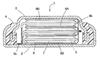
- FIG. 1 is a longitudinal sectional view schematically showing an example of a flat nonaqueous secondary battery according to an embodiment of the present invention.
- FIG. 2 is a partially enlarged cross-sectional view of FIG.
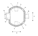
- FIG. 3 is a plan view schematically showing an example of the positive electrode of the flat nonaqueous secondary battery according to the embodiment of the present invention.
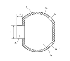
- FIG. 4 is a plan view schematically illustrating an example of a separator of a flat nonaqueous secondary battery according to an embodiment of the present invention.
- FIG. 5 is a plan view of a separator used in the flat nonaqueous secondary battery of the example.
- FIG. 1 is a longitudinal sectional view showing a battery case (an outer case 2 and a sealing case 3) and an insulating gasket 4 of a flat non-aqueous secondary battery 1 (hereinafter also simply referred to as a battery).
- FIG. 2 is an enlarged view of a part of FIG. 1 and a sectional view of the electrode group.
- the flat non-aqueous secondary battery 1 includes a positive electrode 5 and a negative electrode 6 in a space (sealed space) formed by an outer case 2, a sealing case 3, and an insulating gasket 4.
- a stacked electrode group and a nonaqueous electrolyte solution (not shown) that are stacked so that their planes are substantially parallel (including parallel) to the flat surface (upper and lower surfaces in FIG. 1) of the battery 1 are accommodated. It is constituted by being done.
- the sealing case 3 is fitted into the opening of the outer case 2 with the insulating gasket 4 sandwiched between the sealing case 3 and the outer case 2.
- the opening end of the outer case 2 is bent so as to be deformed inward of the battery.
- the insulating gasket 4 is sandwiched between the sealing case 3 and the outer case 2, so that the opening of the outer case 2 is sealed and a sealed space is formed inside the battery.
- the outer case 2 and the sealing case 3 are made of a metal material such as stainless steel.
- the insulating gasket 4 is made of an insulating resin such as nylon.
- the positive electrode 5 includes a plate-like current collector 52 and a positive electrode mixture layer 51 formed on one or both surfaces of the current collector 52 as shown in FIGS. 1 and 2.
- FIG. 3 schematically shows a plan view of the positive electrode 5.
- the positive electrode 5 has a main body portion 5a (positive electrode main body portion) and a current collecting tab portion that protrudes from the main body portion 5a in plan view and has a narrower width (length in the vertical direction in FIG. 3) than the main body portion 5a. 5b (positive electrode current collecting tab part).
- the main body 5 a of the positive electrode 5 is configured by forming a positive electrode mixture layer 51 on one or both surfaces of a current collector 52 as shown in FIG. On the other hand, in the current collecting tab portion 5b of the positive electrode 5, the positive electrode mixture layer 51 is not formed on the surface of the current collector 52, and the current collector 52 is exposed.
- the negative electrode 6 includes a plate-like current collector 62 and a negative electrode agent layer 61 formed on one side or both sides of the current collector 62.
- the negative electrode 6 also has a main body portion 6 a and a current collecting tab portion 6 b that protrudes from the main body portion 6 a in a plan view and is narrower than the main body portion 6 a.
- the negative electrode in which the negative electrode layer 61 is formed on both sides of the current collector 62 is represented as a negative electrode 6A
- the negative electrode in which the negative electrode layer 61 is formed on only one side of the current collector 62 is This is represented as a negative electrode 6B (see FIG. 1).
- the main body 6 a of the negative electrode 6 is configured by forming a negative electrode agent layer 61 on one or both surfaces of the current collector 62.
- the negative electrode agent layer 61 is not formed on the surface of the current collector 62, and the current collector 62 is exposed.
- the upper and lower ends of the electrode group are negative electrodes 6B and 6B.
- These negative electrodes 6B and 6B are arranged in the battery so that the negative electrode agent layer 61 is located on the surface of the current collector 62 on the inner side of the battery.
- the exposed surface of the current collector 62 of the negative electrode 6B located on the upper side in FIG. 1 is welded to or in contact with the inner surface of the sealing case 3, so that the sealing case 3 and the negative electrode 6B are connected to each other. Electrically connected. That is, in the flat nonaqueous secondary battery 1 of the present embodiment, the sealing case 3 also serves as the negative electrode terminal.
- the negative electrode 6 (the negative electrode 6A in which the negative electrode agent layer 61 is formed on both surfaces of the current collector 62 and the negative electrode 6B in which the negative electrode agent layer 61 is formed on only one surface of the current collector 62).
- the current collecting tab portion 6b is electrically connected to each other.
- the current collection tab part 6b of each negative electrode 6 is mutually connected by welding, for example.
- the positive electrode 5 has the current collecting tab portions 5b electrically connected to each other.
- the current collecting tab portions 5b connected to each other are welded to or in contact with the inner surface of the outer case 2 so that the outer case 2 and the positive electrode 5 are electrically connected. That is, in the flat nonaqueous secondary battery 1 of the present embodiment, the outer case 2 also serves as a positive electrode terminal.
- An insulating seal 8 made of polyethylene terephthalate (PET), polyimide, or the like is provided between the negative electrode 6B located at the bottom of the electrode group and the outer case 2 that also serves as a positive electrode terminal for the purpose of insulating the two. Has been placed.
- FIG. 4 schematically shows a plan view of the separator 7. 4 assumes a case of a stacked electrode group in which the positive electrode 5 and the negative electrode 6 covered with the separator 7 are stacked, and the positive electrode 5 covered with the separator 7 is indicated by a dotted line.
- a current collecting tab portion 6b of the negative electrode 6 disposed on the lower side is indicated by a one-dot chain line.
- the binding tape 9 for suppressing the positional shift of each component of an electrode group is shown with the dashed-two dotted line.
- the negative electrode since the negative electrode is disposed so as to sandwich the positive electrode 5, in the state illustrated in FIG. 4, the negative electrode is also disposed above the separator 7 (frontward in the figure).
- the separator 7 is welded to the other separator 7 disposed on the opposite side of the positive electrode 5 (indicated by a dotted line in the figure) at the peripheral edge.
- the two separators 7 form a bag-shaped member that can accommodate the positive electrode 5 therein. That is, as shown in FIG. 4, the two separators 7 sandwiching the positive electrode 5 are welded to each other at the respective peripheral portions, thereby joining the joints 7 c (parts with lattice hatching in FIG. 4). ) Is formed.
- Each separator 7 includes a main body portion 7a that covers the entire surface of the main body portion 5a of the positive electrode 5, and an overhang portion 7b that protrudes from the main body portion 7a so as to cover a boundary portion between the current collecting tab portion 5b of the positive electrode 5 and the main body portion 5a. have.
- the main body part 7a has a larger area than the main body part 5a so as to cover the main body part 5a of the positive electrode 5 in plan view. At least a part of the peripheral portion of the main body portion 7a constitutes the above-described joint portion 7c.
- the separator 7 has a heat shrinkage ratio Ca at 100 ° C. in an arbitrary direction A of 1 to 20%, and a heat shrinkage ratio at 100 ° C. in a direction B perpendicular to the direction A is Cb (%). It is constituted by a microporous film made of a thermoplastic resin having a ratio Ca / Cb between the heat shrinkage ratio Ca and the heat shrinkage ratio Cb of 1.5 or more, preferably 2 or more. Note that the thermal shrinkage Cb of the microporous film constituting the separator is preferably 0% to 10%.
- thermal shrinkage (%) 100 x (dimension before throwing-dimension after throwing) / (dimension before throwing)
- the microporous membrane is usually produced through a stretching process. Therefore, generally, the distortion in the manufacturing direction (MD direction) is larger than that in the direction orthogonal to the manufacturing direction (TD direction). Therefore, in such a microporous film, the thermal shrinkage rate is anisotropic, and the thermal shrinkage rate in the direction corresponding to the MD direction is large, while the thermal shrinkage rate is small in the TD direction. That is, usually, the direction A in the microporous film corresponds to the MD direction, and the direction B corresponds to the TD direction.
- the direction A in the microporous membrane constituting the separator 7 is indicated by a dotted arrow, and the direction B is indicated by a solid arrow.
- the separators 7 existing on both surfaces of the positive electrode 5 are arranged such that the direction B is in the direction in which the projecting portion 7b protrudes from the main portion 7a (lateral direction in FIG. 4). It is formed to be substantially parallel (including parallel, the same applies hereinafter). That is, the direction B is substantially parallel to the direction in which the current collecting tab portion 5b of the positive electrode 5 protrudes from the main body portion 5a.
- the present embodiment as shown in FIG.
- the direction in which the protruding portion 7 b projects from the main body portion 7 a in the separator 7 coincides with the direction in which the current collecting tab portion 5 b projects from the main body portion 5 a in the positive electrode 5.
- the protruding tab 7b of the separator 7 can cover the current collecting tab portion 5b of the positive electrode 5, the protruding direction of the protruding portion 7b may be different from the protruding direction of the collecting tab portion 5b. Good.
- the current collecting tab of the positive electrode 5 among the peripheral portions of the protruding portions 7 b in the two separators 7 arranged on both surfaces of the positive electrode 5.
- a joint portion cannot be provided in a portion where the portion 5b protrudes. Therefore, for example, when the direction in which the thermal contraction rate of the separator 7 is large (the direction A) is substantially parallel to the direction in which the current collecting tab portion 5b of the positive electrode 5 protrudes from the main body portion 5a, When the temperature becomes high, large shrinkage occurs in the overhanging portion 7b.
- the overhanging portion is also obtained when the temperature inside the battery becomes high. Shrinkage at 7b is suppressed. Therefore, contact between the current collecting tab portion 5b of the positive electrode 5 and the negative electrode 6 can be prevented, and occurrence of a short circuit can be suppressed.
- the direction A that is more likely to be thermally contracted is indicated by a dotted arrow in FIG. It becomes the direction shown by.
- shrinkage at a high temperature is suppressed by the joint 7 c formed at the peripheral edge of the separator 7.
- the flat non-aqueous secondary battery 1 of the present embodiment can ensure good safety even at high temperatures by adopting the above configuration.
- the peripheral portions of the two separators 7 are welded together to form the joint 7c.
- a layer made of a resin is interposed between the separators 7, and this layer and the two separators 7 are welded, or both sides of this layer are bonded.
- a method of applying an adhesive or the like and bonding the two separators 7 is conceivable. In this way, when another layer is interposed between the two separators, the strength of the joint portion tends to be smaller than the other portions of the separator 7. For this reason, for example, when the inside of the battery becomes high temperature and the separator 7 contracts, there is a possibility that the joint portion peels and the positive electrode and the negative electrode are in direct contact with each other.
- the peripheral portions of the two separators are directly welded to each other, so that the strength of the joint 7c is substantially equal to the strength of the separator itself. It becomes. Therefore, even if the temperature in the battery becomes a high temperature at which the separator can shrink, the peeling of the joint portion 7c is suppressed. Therefore, since the contact between the positive electrode and the negative electrode is prevented, the battery is highly safe.
- the positive electrode 5 is stacked on one separator 7 and further on it. After the separators 7 are stacked, a method of welding the peripheral portions of these separators 7 can be employed. It is also possible to employ a method in which two separators 7 are stacked, the peripheral portions thereof are welded to join the separators 7 together, and then the positive electrode 5 is inserted between the separators 7.
- peripheral parts in the main part 7a of the separator 7 may be the joint part 7c, for example, as shown in FIG. 4, a part of the peripheral part is not welded so as not to weld the separators 7 to each other. You may leave as part 7d and 7d (non-joining part).
- part 7d and 7d non-joining part
- two separators 7 are welded to form a bag and the positive electrode 5 is accommodated therein, or the positive electrode 5 is disposed on one separator 7 and another separator 7 is disposed on the positive electrode 5.
- the peripheral edge portion of the separator 7 is welded to form a bag shape in a state in which air is disposed, air may remain in the bag-shaped member formed by the separator 7.
- the separator 7 is pressed between the positive electrode 5 and the negative electrode 6 when the exterior case 2 and the sealing case 3 are caulked by providing the non-welded portion 7d described above, Residual air is discharged well out of the separator 7 through the non-welded portions 7d and 7d. Therefore, it is possible to prevent the occurrence of problems due to residual air in the separator (for example, problems such as non-uniform reaction during power generation and reduced capacity).
- the number of the non-welded portions 7d is preferably about 1 to 5 from the viewpoint of suppressing a decrease in the productivity of the battery 1.
- the length of the outer edge of the non-welded portion 7d in the main body portion 7a of the separator 7 is equal to the total length of the outer edge of the main body portion 7a of the separator 7 About 15% to 60% of the total length).
- 40% or more (preferably 70% or more) of the entire length of the outer edge is a joint portion.
- the peripheral edge of the separator 7 can be welded by, for example, a hot press.
- the heating temperature may be higher than the melting point of the thermoplastic resin constituting the separator 7.
- it is preferably performed at a temperature higher by 10 ° C. to 50 ° C. than the melting point of the thermoplastic resin.
- the heating press time is not particularly limited as long as a good joint can be formed, but is preferably about 1 to 10 seconds.
- the electrodes at the upper and lower ends (the outermost two electrodes) of the electrode group are both negative electrodes 6, but not limited to this, the electrodes at the upper and lower ends of the electrode group (the two outermost electrodes) One or both of them may be the positive electrode 5.
- the positive electrode 5 is attached to both surfaces of the current collector 52.
- the positive electrode mixture layer 51 may be provided, and the current collecting tab portion 5b may be in contact with a battery case (for example, the outer case 2) that also serves as a positive electrode terminal.
- the electrical power collector 52 has the positive mix layer 51 only in the single side
- both the upper and lower electrodes (two outermost electrodes) in the electrode group are the positive electrodes 5
- the current collecting tab portions 6b of the respective negative electrodes 6 are electrically connected to each other, and the current collecting tabs are connected.
- the battery case and the negative electrode 6 can be electrically connected by welding or contacting the portion 6b with the inner surface of a battery case (for example, the sealing case 3) that also serves as the negative electrode terminal.
- separators are arranged on both sides of the positive electrode whose both sides are opposed to the negative electrode.
- the separator does not have to be arranged on both surfaces, and the separator is provided only on the surface facing the negative electrode. May be arranged.
- a polyethylene terephthalate between the battery case serving also as the negative electrode terminal and the positive electrode 5 ( An insulator such as an insulating seal made of PET) or polyimide is disposed.
- the electrical connection between the current collecting tab portion 5b of each positive electrode 5 and the battery case also serving as the positive electrode terminal, and the electrical connection between the current collecting tab portion 6b of each negative electrode 6 and the battery case serving also as the negative electrode terminal are positive electrodes.
- 5 and the negative electrode 6 may be realized by a separate lead body (lead body made of metal foil or the like).
- the positive electrode mixture layer 51 of the positive electrode 5 is a layer containing a positive electrode active material, a conductive additive, a binder, and the like.
- M is at least one metal element selected from the group consisting of Mg, Mn, Fe, Co, Ni, Cu, Zn, Al and Cr, and 0 ⁇ x ⁇ 1.1, 0 ⁇ y ⁇ 1.0, and 2.0 ⁇ z ⁇ 2.2.
- These positive electrode active materials may be used individually by 1 type, and may use 2 or more types together.
- examples of the conductive assistant for the positive electrode 5 include carbon black, flaky graphite, ketjen black, acetylene black, and fibrous carbon.
- examples of the binder of the positive electrode 5 include polytetrafluoroethylene (PTFE), polyvinylidene fluoride (PVDF), carboxymethyl cellulose, and styrene butadiene rubber.
- the positive electrode 5 is prepared by dispersing a positive electrode mixture obtained by mixing a positive electrode active material, a conductive additive, and a binder in water or an organic solvent to prepare a positive electrode mixture-containing paste. It is manufactured by applying to one or both sides of a current collector 52 made of metal foil, expanded metal, plain weave wire mesh, etc., drying, and then pressure forming.
- a positive electrode mixture-containing paste may be prepared by dissolving or dispersing a binder in water or a solvent in advance and mixing it with a positive electrode active material or the like.
- the manufacturing method of the positive electrode 5 is not limited to the above-described method, and other methods may be used.
- the composition of the positive electrode 5 is, for example, 75% by mass to 90% by mass of the positive electrode active material, 5% by mass to 20% by mass of the conductive assistant, and 3% by mass of the binder in 100% by mass of the positive electrode mixture constituting the positive electrode 5. % To 15% by mass is preferable.
- the thickness of the positive electrode mixture layer 51 is preferably 30 ⁇ m to 200 ⁇ m, for example.
- the material of the current collector 52 of the positive electrode 5 of the positive electrode 5 aluminum or an aluminum alloy is preferable.
- the opposing area between the positive electrode mixture layer 51 and the negative electrode agent layer 61 is increased and the load of the battery 1 is increased.
- the thickness of the current collector 52 is preferably, for example, 8 ⁇ m to 20 ⁇ m.
- the negative electrode 6 used in the present embodiment includes a configuration in which the active material includes lithium, a lithium alloy, a carbon material capable of occluding and releasing lithium ions, lithium titanate, and the like.
- the lithium content is preferably 1 atomic% to 15 atomic%, for example.
- the carbon material that can be used for the negative electrode active material include artificial graphite, natural graphite, low crystalline carbon, coke, and anthracite.
- the lithium titanate represented by the general formula Li x Ti y O 4 can be obtained, for example, by heat treating titanium oxide and a lithium compound at 760 ° C. to 1100 ° C. As the titanium oxide, either anatase type or rutile type can be used, and examples of the lithium compound include lithium hydroxide, lithium carbonate, and lithium oxide.
- the negative electrode active material is lithium or a lithium alloy
- the negative electrode 6 is made by pressure bonding lithium or a lithium alloy to a current collector 62 such as a metal net, and the negative electrode made of lithium, a lithium alloy, or the like on the surface of the current collector 62 It is obtained by forming the agent layer 61.
- a carbon material or lithium titanate is used as the negative electrode active material, for example, a negative electrode composite obtained by mixing a carbon material or lithium titanate with a binder as the negative electrode active material and, if necessary, a conductive additive.
- a negative electrode mixture-containing paste is prepared by dispersing the agent in water or an organic solvent.
- a negative electrode mixture-containing paste may be prepared by dissolving or dispersing a binder in water or a solvent in advance and mixing it with a negative electrode active material or the like.
- the manufacturing method of the negative electrode 6 is not limited to the above-described method, and other methods may be used.
- a binder and conductive support agent of a negative electrode the various binders and conductive support agents which were illustrated previously as what can be used for a positive electrode can be used.
- the composition of the negative electrode 6 when a carbon material is used as the negative electrode active material is, for example, 80% by mass to 95% by mass of the carbon material and 3% by mass to 15% of the binder in 100% by mass of the negative electrode mixture constituting the negative electrode 6. It is preferable to set it as the mass%.
- the conductive auxiliary is preferably 5% by mass to 20% by mass.
- the composition of the negative electrode 6 when lithium titanate is used as the negative electrode active material is, for example, 75% to 90% by mass of lithium titanate and 3% of binder in 100% by mass of the negative electrode mixture constituting the negative electrode 6. It is preferable to set the mass to 15% by mass.
- the conductive auxiliary is preferably 5% by mass to 20% by mass.
- the thickness of the negative electrode agent layer 61 in the negative electrode 6 is preferably 40 ⁇ m to 200 ⁇ m, for example.
- the material of the current collector 62 of the negative electrode 6 of the negative electrode 6 copper or a copper alloy is preferable.
- the opposing area of the positive electrode mixture layer 51 and the negative electrode agent layer 61 is increased by increasing the number of stacked positive electrodes 5 and negative electrodes 6 in the battery 1 while reducing the thickness of the entire negative electrode 6. From the viewpoint of improving load characteristics, it is preferable to use a metal foil for the current collector 62.
- the thickness of the current collector 62 is preferably, for example, 5 ⁇ m to 30 ⁇ m.
- thermoplastic resin constituting the separator 7 for example, polyolefins such as polyethylene (PE), polypropylene (PP), ethylene-propylene copolymer, and polymethylpentene are preferable. From the viewpoint of welding the separators 7 together, or arranging and welding the same type of resin as that constituting the separators 7 between the separators 7, the differential scanning according to the provisions of JIS K 7121 More preferred is a polyolefin having a melting temperature of 100 ° C. to 180 ° C. measured using a calorimeter (DSC).
- DSC calorimeter
- thermoplastic resin microporous film constituting the separator 7 may be any form as long as it has an ionic conductivity sufficient to obtain necessary battery characteristics.
- an ion-permeable microporous film (a microporous film that is widely used as a battery separator) that is formed by a conventionally known dry or wet stretching method or the like and has a large number of pores is preferable.
- the thickness of the separator 7 is preferably 5 ⁇ m to 25 ⁇ m, for example.
- the porosity is preferably 30% to 70%, for example.
- the positive electrode 5, the negative electrode 6, and the separator 7 are arranged such that the current collecting tab portions 5b of the respective positive electrodes 5 face the same direction in a plan view of the electrode group, and
- the current collecting tab portion 6b of each negative electrode 6 is preferably arranged so as to face the same direction in a plan view of the electrode group.
- the electric tab portion 5b and the current collecting tab portion 6b are arranged at positions facing each other in plan view.
- the electrode group composed of the positive electrode 5, the negative electrode 6 and the separator 7 is preferably bound around the outer periphery with a binding tape 9 made of polypropylene having chemical resistance. Thereby, position shift of each component (the positive electrode 5 covered with the separator 7 and the negative electrode 6) can be suppressed.
- the total number of layers of the electrode is at least 4, but it is also possible to have a larger number of layers (5 layers, 6 layers, 7 layers, 8 layers, etc.). However, if the number of stacked positive electrodes 5 and negative electrodes 6 is increased too much, the merit as a flat battery may be reduced. Therefore, it is usually preferable to use 40 layers or less.
- non-aqueous electrolyte examples include cyclic carbonates such as ethylene carbonate (EC), propylene carbonate, butylene carbonate, and vinylene carbonate; chain carbonates such as dimethyl carbonate, diethyl carbonate (DEC), and methyl ethyl carbonate; Ethers such as 2-dimethoxyethane, diglyme (diethylene glycol methyl ether), triglyme (triethylene glycol dimethyl ether), tetraglyme (tetraethylene glycol dimethyl ether), 1,2-dimethoxyethane, 1,2-diethoxymethane, tetrahydrofuran; An electrolytic solution prepared by dissolving an electrolyte (lithium salt) in an organic solvent at a concentration of about 0.3 mol / L to 2.0 mol / L is used. Rukoto can.
- the said organic solvent may be used individually by 1 type, respectively, and may use 2 or more types together.
- electrolyte examples include LiBF 4 , LiPF 6 , LiAsF 6 , LiSbF 6 , LiClO 4 , LiCF 3 SO 3 , LiC 4 F 9 SO 3 , LiN (CF 3 SO 2 ) 2 , LiN (C 2 F 5 SO 2 ) Lithium salts such as 2 are mentioned.
- the planar shape of the flat non-aqueous secondary battery 1 is not particularly limited, and may be a polygonal shape such as a square (for example, a quadrangle) in addition to a circular shape that is the mainstream of conventionally known flat batteries.
- the polygon such as a square as the planar shape of the battery 1 in this specification includes a shape in which the corner is cut off and a shape in which the corner is curved.
- the planar shape of the main body portions 5 a and 6 a of the positive electrode 5 and the negative electrode 6 may be a shape corresponding to the planar shape of the battery 1.
- the main body portions 5a and 6a may be polygons including rectangles such as rectangles and squares in addition to substantially circular shapes.
- the portion where the current collecting tab portion of the counter electrode is disposed is shown in FIG. 3 in order to prevent contact with the current collecting tab portion of the counter electrode.
- the present invention is not limited to this, and the outer case 2 is a negative electrode case and a sealing case as necessary. 3 may be a positive electrode case.
- the two separators 7 are joined at the peripheral edge of the main body 7a, but one separator may be folded and joined.
- the flat non-aqueous secondary battery 1 can be applied to the same use as a conventionally known flat non-aqueous secondary battery.
- Example 1 Preparation of positive electrode> A positive electrode was prepared using LiCoO 2 as a positive electrode active material, carbon black as a conductive additive, and PVDF as a binder. First, LiCoO 2 : 93 parts by weight and carbon black: 3 parts by weight were mixed, and the resulting mixture and PVDF: 4 parts by weight were previously dissolved in N-methyl-2-pyrrolidone (NMP). The paste was mixed with the solution to prepare a positive electrode mixture-containing paste. Here, each said weight part is a value when a positive electrode mixture is 100 weight part. And the positive mix containing paste obtained as mentioned above was apply
- NMP N-methyl-2-pyrrolidone
- the positive mix containing paste when apply
- the strip-shaped positive electrode has the shape shown in FIG. 3 so that the positive electrode mixture layer forming portion is a main body portion (arc portion diameter 15.1 mm) and the positive electrode mixture layer non-forming portion is a current collecting tab portion.
- the battery positive electrode was obtained.
- the separator 7 is disposed on both surfaces of the battery positive electrode, and the portion (7c) shown in FIG. 4 is welded by a hot press (temperature 170 ° C., press time 2 seconds).
- the joining portion 7c was formed at a part of the peripheral edge portion of the main body portion 7a in the two separators 7, and the battery positive electrode and the separator 7 were integrated.
- variety of the junction part in the two separators 7 was 0.3 mm. Of the outer edges of the main body portion 7a of the two separators 7, 90% of the total length was defined as the joint portion 7c.
- a negative electrode was prepared using graphite as the negative electrode active material and PVDF as the binder.
- the graphite: 94 parts by weight, PVDF: 6 parts by weight, and a binder solution previously dissolved in NMP were mixed to prepare a negative electrode mixture-containing paste.
- each said weight part is a value when a negative electrode mixture is 100 weight part.
- the negative mix containing paste obtained as mentioned above was apply
- the portion where the coated portion is the front surface is the back surface
- the applied negative electrode mixture-containing paste was dried to form a negative electrode mixture layer, and then roll-pressed and cut into a predetermined size to obtain a strip-shaped negative electrode.
- the negative electrode was formed so that the width was 40 mm and the thickness of the negative electrode mixture layer forming part was 190 ⁇ m when formed on both sides of the current collector, and 100 ⁇ m when formed on one side of the current collector. .
- the strip-shaped negative electrode has the same shape as the positive electrode, with the negative electrode mixture layer forming part being the main body part (arc portion diameter 16.3 mm) and the negative electrode mixture layer non-forming part being the current collecting tab part. Punched out.
- a negative electrode for a battery having a negative electrode mixture layer on one side of the current collector and a negative electrode for a battery having negative electrode mixture layers on both sides of the current collector were obtained.
- a part of the negative electrode for a battery having the negative electrode mixture layer on one side of the current collector was punched after a PET film having a thickness of 100 ⁇ m was attached to the exposed surface of the current collector of the strip-shaped negative electrode. .
- An electrode group was configured using two negative electrodes (one of which was a PET film attached to the exposed surface of the current collector). Specifically, the battery positive electrode and the battery negative electrode were alternately stacked so that the battery negative electrode having the negative electrode mixture layer formed on one side of the current collector was positioned on the outermost part. And the current collection tab part of each battery positive electrode was welded collectively, and the electrode collection was formed by welding the current collection tab part of each battery negative electrode collectively.
- the electrode group was placed in the outer case so that the PET film faced the inner surface of the outer case, and the collected current collecting tab portion of the positive electrode was welded to the inner surface of the outer case.
- an insulating gasket is attached to the sealing case, and a non-aqueous electrolyte (ethylene carbonate and methyl ethyl carbonate in a mixed solvent having a volume ratio of 1: 2 and LiPF 6 at a concentration of 1.2 mol / l is placed in the sealing case. After 200 mg of the dissolved solution) is put, an outer case containing the electrode group is put on.
- the flat non-aqueous secondary battery is designed to discharge at a current value of 14 mA and a discharge capacity of 70 mAh.
- Comparative Example 2 The same PE microporous membrane separator as in Example 1 has the shape shown in FIGS. 4 and 5 (the length of i in FIG. 5 is 5 mm and the length of ii is 0.8 mm), and the direction A is A flat non-aqueous secondary battery similar to that of Example 1 was produced except that the overhanging part was cut out so as to be parallel to the direction protruding from the main part.
- the external short circuit test was conducted on each of the 10 flat non-aqueous secondary batteries of Examples 1 and 2 and Comparative Examples 1 and 2.
- each battery was externally short-circuited at a resistance of 100 m ⁇ for 15 minutes in an environment of 24 ° C., and then the open circuit voltage of each battery was measured after 24 hours. Batteries with an open circuit voltage of 0 V were used as internal short-circuit products, and the number of generated batteries was examined. These results are shown in Table 1.
- the flat non-aqueous secondary batteries of Examples 1 and 2 in which separators are appropriately arranged have good occurrence of internal short circuit even when the temperature in the battery rises due to the external short circuit test. It is suppressed. Therefore, the flat nonaqueous secondary batteries of Examples 1 and 2 have higher safety than the batteries of Comparative Examples 1 and 2 in which the characteristics of the separators themselves used and the arrangement of the separators are not appropriate.
- the flat nonaqueous secondary batteries of Examples 1 and 2 were disassembled after the external short circuit test. In these batteries, no shrinkage was observed at the protruding portion of the separator, and no separation of the joint between the separators occurred.
Landscapes
- Chemical & Material Sciences (AREA)
- Chemical Kinetics & Catalysis (AREA)
- Electrochemistry (AREA)
- General Chemical & Material Sciences (AREA)
- Engineering & Computer Science (AREA)
- Materials Engineering (AREA)
- Manufacturing & Machinery (AREA)
- Secondary Cells (AREA)
- Cell Separators (AREA)
- Connection Of Batteries Or Terminals (AREA)
- Battery Electrode And Active Subsutance (AREA)
Abstract
良好な安全性を有する扁平形非水二次電池を提供する。扁平形非水二次電池(1)は、外装ケース(2)と封口ケース(3)と電極群とを備える。電極群は、交互に積層される複数の正極(5)及び負極(6)と、セパレータ(7)とを有する。正極(5)は、本体部(5a)(正極本体部)と集電タブ(5b)(正極集電タブ部)とを備えている。セパレータ(7)は、正極(5)の本体部(5a)を覆う主体部(7a)と、正極(5)の本体部(5a)と集電タブ部(5b)との境界部分を覆う張り出し部(7b)とを有する。セパレータ(7)は、方向Aの熱収縮率が、該方向Aに直交する方向Bの熱収縮率よりも大きい。セパレータ(7)は、前記方向Bが、正極(5)の集電タブ部(5b)が本体部(5a)から突出する方向に対して略平行になるように形成されている。主体部(7a)の周縁部の少なくとも一部には、互いに直接溶着される接合部を有する。
Description
本発明は、良好な安全性を有する扁平形非水二次電池に関する。
一般にコイン形電池やボタン形電池と称される扁平形の非水二次電池は、正極及び負極がセパレータを介して積層された電極体と、非水電解液とが、外装ケース及び封口ケースによって形成された空間内に収容された構造を有している。
前記のような扁平形非水二次電池としては、正極及び負極において、集電体の片面または両面に正極合剤層や負極合剤層を形成するとともに、集電体の一部を、正極合剤層や負極合剤層を形成することなく露出させて、集電タブとして利用する構成が知られている。このような扁平形非水二次電池では、前記集電タブを、電極体と端子を兼ねる外装ケースや封口ケースとの電気的な接続に利用している。
一方、前記のような構成を有する正極を、袋状に成形したセパレータ内に挿入した状態で負極と積層することによって電極群を形成した構成が知られている(例えば、特表2004-509443号公報や特開2008-91100号公報)。この袋状のセパレータは、2枚のセパレータの間に、表面に接着成分を有するポリエステル樹脂フィルムなどの絶縁性高分子フィルムを配置して、該接着成分によってフィルムとセパレータとを接着したり(例えば特表2004-509443号公報)、2枚のセパレータ同士を溶着したり(例えば特開2008-91100号公報)することにより形成される。
ところで、非水二次電池では、ポリエチレンなどのポリオレフィンによって構成された微多孔膜(微孔性フィルム)をセパレータとして使用することが一般的である。こうした微多孔膜は、通常、一軸延伸や二軸延伸を行う工程を経て製造されるが、この延伸によって微多孔膜にひずみが生じるため、高温に曝されると収縮が生じやすい。したがって、非水二次電池内が高温状態となって、セパレータに収縮が起こると、正極と負極とが直接、接触して短絡が生じる虞がある。
一方、前記の袋状のセパレータを用いた電池の場合、正極を包む2枚のセパレータ同士を接合した構成であるため、高温下でもセパレータの収縮が生じ難い。しかしながら、実際には、高温下における非水二次電池の短絡の抑制効果が、必ずしも良好でないことが本発明者の検討により明らかとなった。
本発明は、前記事情に鑑みてなされたものであり、その目的は、高温下における安全性が良好な扁平形非水二次電池を提供することにある。
本発明の一実施形態に係る扁平形非水二次電池は、外装ケースと封口ケースとによって形成される空間内に配置される電極群を備え、該電極群は、交互に積層される複数の正極及び複数の負極と、前記正極と前記負極との間に位置し、該正極を挟み込むように配置されるセパレータとを備えていて、前記正極は、正極本体部と、平面視で、前記正極本体部から突出していて、該正極本体部よりも幅の狭い正極集電タブ部とを有しており、前記セパレータは、前記正極本体部を覆う主体部と、前記主体部から突出していて、前記正極集電タブ部と前記正極本体部との境界部分を覆う張り出し部とを有するとともに、任意の方向Aにおける100℃での熱収縮率Caが該方向Aに直交する方向Bにおける100℃での熱収縮率Cbよりも大きい熱可塑性樹脂製の微多孔膜からなり、前記方向Bが、前記正極集電タブ部が前記正極本体部から突出する方向に対して略平行になるように形成されており、前記正極を挟み込むように配置されるセパレータの主体部は、セパレータ同士が主体部の周縁部の少なくとも一部で互いに直接溶着されることにより形成される接合部を有する。
なお、電池業界では、高さよりも径の方が大きい扁平形電池を、コイン形電池またはボタン形電池と呼んでいる。しかしながら、コイン形電池とボタン形電池との間に明確な差異はなく、本発明の扁平形非水二次電池には、コイン形電池及びボタン形電池のいずれもが含まれる。
本発明の一実施形態によれば、高温下における安全性が良好な扁平形非水二次電池を提供することができる。
図1及び図2に、本発明の一実施形態に係る扁平形非水二次電池の一例を模式的に示す。図1は、扁平形非水二次電池1(以下、単に電池ともいう)の電池ケース(外装ケース2及び封口ケース3)及び絶縁ガスケット4を断面で示した縦断面図である。図2は、図1の一部を拡大するとともに、電極群を断面で示した図である。図1及び図2に示すように、扁平形非水二次電池1は、外装ケース2、封口ケース3及び絶縁ガスケット4によって形成される空間(密閉空間)内に、正極5及び負極6が、それらの平面が電池1の扁平面(図1における上下の面)に略平行(平行を含む)になるように積層された積層型の電極群と、非水電解液(図示しない)とが収容されることにより構成される。
封口ケース3は、外装ケース2の開口部に、該外装ケース2との間に絶縁ガスケット4を挟み込んだ状態で嵌合されている。外装ケース2の開口端部は、電池内方に変形するように曲げられている。これにより、絶縁ガスケット4は、封口ケース3と外装ケース2との間に挟みこまれた状態となるため、該外装ケース2の開口部が封口されて、電池内部に密閉空間が形成される。外装ケース2及び封口ケース3は、ステンレス鋼などの金属材料によって構成される。絶縁ガスケット4は、ナイロンなどの絶縁性を有する樹脂によって構成される。
正極5は、図1及び図2に示すように、板状の集電体52と、該集電体52の片面上または両面上に形成された正極合剤層51とを備えている。図3に、正極5の平面図を模式的に示す。正極5は、本体部5a(正極本体部)と、平面視で、該本体部5aから突出していて、該本体部5aよりも幅(図3における上下方向の長さ)の狭い集電タブ部5b(正極集電タブ部)とを有している。
正極5の本体部5aは、図2に示すように、集電体52の片面または両面に、正極合剤層51を形成することによって構成される。一方、正極5の集電タブ部5bでは、集電体52の表面に正極合剤層51が形成されておらず、該集電体52が露出している。
負極6は、図1及び図2に示すように、板状の集電体62と、該集電体62の片面上または両面上に形成された負極剤層61とを備えている。負極6についても、正極5と同様、本体部6aと、平面視で、該本体部6aから突出していて、該本体部6aよりも幅の狭い集電タブ部6bとを有している。なお、以下の説明において、集電体62の両面に負極剤層61が形成された負極を、負極6Aと表すとともに、集電体62の片面のみに負極剤層61が形成された負極を、負極6Bと表す(図1参照)。
負極6の本体部6aは、集電体62の片面または両面に、負極剤層61を形成することによって構成される。一方、負極6の集電タブ部6bでは、集電体62の表面に負極剤層61が形成されておらず、該集電体62が露出している。
図1に示すように、本実施形態の扁平形非水二次電池1では、電極群の上下両端が負極6B、6Bとなっている。これらの負極6B、6Bは、集電体62の電池内方側の面に負極剤層61が位置するように、電池内に配置されている。そして、図1の上側に位置する負極6Bの集電体62の露出面は、封口ケース3の内面に溶接されているか、または接触していて、これにより、該封口ケース3と負極6Bとが電気的に接続されている。すなわち、本実施形態の扁平形非水二次電池1では、封口ケース3が負極端子を兼ねている。
負極6(集電体62の両面に負極剤層61が形成された負極6A、及び、集電体62の片面のみに負極剤層61が形成された負極6B)は、図1に示すように、集電タブ部6bで互いに電気的に接続されている。なお、各負極6の集電タブ部6bは、例えば溶接によって互いに接続される。
正極5は、図1及び図2に示すように、集電タブ部5bが互いに電気的に接続されている。そして、互いに接続された集電タブ部5bは、外装ケース2の内面に溶接されているか、または接触していて、これにより、該外装ケース2と正極5とが電気的に接続されている。すなわち、本実施形態の扁平形非水二次電池1では、外装ケース2が正極端子を兼ねている。なお、電極群の最下部に位置する負極6Bと、正極端子を兼ねる外装ケース2との間には、両者を絶縁する目的で、ポリエチレンテレフタレート(PET)やポリイミドなどによって構成された絶縁シール8が配置されている。
図1及び図2に示すように、正極5は、本体部5aと集電タブ部5bの一部とが、熱可塑性樹脂製の微多孔膜からなるセパレータ7によって覆われている。図4に、セパレータ7の平面図を模式的に示す。なお、この図4では、セパレータ7によって覆われた正極5と負極6とが積層された積層型の電極群の場合を想定していて、セパレータ7によって覆われる正極5を点線で示し、それらの下側に配置される負極6の集電タブ部6bを一点鎖線で示している。また、図4において、電極群の各構成要素の位置ずれを抑えるための結束テープ9を二点鎖線で示している。特に図示しないが、本実施形態では、正極5を挟み込むように負極が配置されるため、図4に示す状態では、セパレータ7の上側(図中手前方向)にも負極が配置される。
セパレータ7は、正極5(図中点線で表示)の反対側に配置される別のセパレータ7と周縁部で互いに溶着されている。これにより、2枚のセパレータ7によって、内部に正極5が収容可能な袋状の部材が形成される。すなわち、図4に示すように、正極5を間に挟み込む2枚のセパレータ7は、それぞれの周縁部に、互いに溶着されることにより接合部7c(図4で格子状のハッチングを付けている部分)が形成される。
各セパレータ7は、正極5の本体部5aの全面を覆う主体部7aと、正極5の集電タブ部5bにおける本体部5aとの境界部分を覆うように主体部7aから突出する張り出し部7bとを有している。主体部7aは、平面視で正極5の本体部5aを覆うように該本体部5aよりも面積が大きい。この主体部7aの周縁部の少なくとも一部は、上述の接合部7cを構成する。
セパレータ7は、任意の方向Aにおける100℃での熱収縮率Caが1~20%であり、該方向Aに直交する方向Bにおける100℃での熱収縮率をCb(%)としたときの熱収縮率Caと熱収縮率Cbとの比Ca/Cbが1.5以上、好ましくは2以上である熱可塑性樹脂製の微多孔膜によって構成される。なお、セパレータを構成する微多孔膜の熱収縮率Cbは、0%~10%であることが好ましい。
なお、本明細書でいう熱収縮率Ca及びCbは、100℃の恒温槽にセパレータを1時間投入し、その前後でのセパレータの寸法を投影機で測定して、その測定結果を用いて下式から算出する。
熱収縮率(%) = 100×(投入前寸法-投入後寸法)/(投入前寸法)
熱収縮率(%) = 100×(投入前寸法-投入後寸法)/(投入前寸法)
前記の通り、微多孔膜は、通常、延伸工程を経て製造される。そのため、一般的に、製造方向(MD方向)のひずみが、製造方向に直交する方向(TD方向)に比べて大きくなる。したがって、こうした微多孔膜では、熱収縮率に異方性があり、MD方向に相当する方向の熱収縮率が大きい一方で、TD方向には熱収縮率が小さくなる。すなわち、通常、微多孔膜における前記方向AはMD方向に相当し、前記方向BはTD方向に相当する。
図4において、セパレータ7を構成する微多孔膜における前記方向Aを点線の矢印で、前記方向Bを実線の矢印でそれぞれ示す。この図4に示すように、本実施形態では、正極5の両面に存在するセパレータ7を、前記方向Bが、張り出し部7bが主体部7aから突出する方向(図4の横方向)に対して略平行(平行を含む。以下同じ。)になるように形成する。すなわち、前記方向Bは、正極5の集電タブ部5bが本体部5aから突出する方向に対して略平行になる。なお、本実施形態では、図4に示すように、セパレータ7において張り出し部7bが主体部7aから突出する方向と、正極5において集電タブ部5bが本体部5aから突出する方向とが一致している。しかしながら、セパレータ7の張り出し部7bによって正極5の集電タブ部5bを覆うことができる構成であれば、張り出し部7bの突出方向は集電タブ部5bの突出方向とは異なる方向であってもよい。
図4に示す通り、本実施形態の扁平形非水二次電池1では、正極5の両面に配置される2枚のセパレータ7における張り出し部7bの周縁部のうち、少なくとも正極5の集電タブ部5bが突出する部分には、接合部を設けることができない。そのため、例えば、セパレータ7の熱収縮率が大きな方向(前記方向A)が、正極5の集電タブ部5bが本体部5aから突出する方向に対して略平行になる場合には、電池内が高温となった際に、張り出し部7bで大きな収縮が生じる。そうすると、正極5の集電タブ部5bにおける本体部5aとの境界部近傍(すなわち、正極5と積層された負極の周辺部分)が露出し、正極5の集電タブ部5bと負極6とが接触して短絡を生じる虞がある。
しかしながら、セパレータ7における前記方向Bを、正極5の集電タブ部5bが本体部5aから突出する方向に対して略平行にした場合には、電池内が高温となった際にも、張り出し部7bにおける収縮が抑制される。そのため、正極5の集電タブ部5bと負極6との接触を防止することができ、短絡の発生を抑えることが可能となる。
なお、セパレータ7における前記方向Bを、正極の集電タブ部5bが本体部5aから突出する方向に対して略平行にした場合、より熱収縮しやすい前記方向Aは、図4に点線の矢印で示す方向となる。この図4に点線の矢印で示す方向では、セパレータ7の周縁部に形成された接合部7cによって、高温時の収縮が抑制される。
本実施形態の扁平形非水二次電池1は、前記の構成を採用することによって、高温下においても良好な安全性を確保することができる。
上述のとおり、2枚のセパレータ7の周縁部同士が溶着されて接合部7cが形成される。2枚のセパレータ7同士を溶着する方法としては、例えば、セパレータ7間に樹脂で構成された層を別途介在させて、この層と2枚のセパレータ7とを溶着したり、この層の両面に接着剤などを塗布して、2枚のセパレータ7と接着したりする方法が考えられる。このように2枚のセパレータの間に別の層を介在させる場合には、セパレータ7の他の部分に比べて接合部の強度が小さくなりやすい。そのため、例えば電池内が高温となってセパレータ7が収縮した際に、接合部が剥離して正極と負極とが直接接触する虞がある。
これに対し、本実施形態の扁平形非水二次電池1では、前記の通り、2枚のセパレータの周縁部同士を直接溶着することから、接合部7cの強度がセパレータ自身の強度とほぼ同等となる。そのため、電池内温度が、セパレータに収縮が生じ得るような高温となっても、接合部7cの剥離が抑制される。したがって、正極と負極との接触が防止されるため、安全性の高い電池となる。
2枚のセパレータ7の周縁部に接合部7cを形成するとともに、これらのセパレータ7の間に正極5を収容するには、例えば、1枚のセパレータ7上に正極5を重ね、更にその上にセパレータ7を重ねた後、これらのセパレータ7の周縁部を溶着する方法が採用できる。また、2枚のセパレータ7を重ね、これらの周縁部を溶着してセパレータ7同士を接合し、その後、これらのセパレータ7間に正極5を挿入する方法を採用することもできる。
なお、セパレータ7の主体部7aにおける周縁部は、全てが接合部7cとなっていてもよいが、例えば、図4に示すように、周縁部の一部を、セパレータ7同士を溶着しない非溶着部7d、7d(非接合部)として残してもよい。例えば、2枚のセパレータ7を溶着して袋状とした後に、その中に正極5を収容した場合や、1枚のセパレータ7上に正極5を配置し、該正極5上に別のセパレータ7を配置した状態でセパレータ7の周縁部を溶着して袋状とした場合には、セパレータ7によって形成される袋状の部材内に空気が残留することがある。しかし、このような場合でも、上述の非溶着部7dを設けることにより、外装ケース2と封口ケース3とをかしめる際に正極5と負極6との間でセパレータ7が圧迫されて、前記の残留空気が非溶着部7d、7dを通じてセパレータ7外へ良好に排出される。そのため、セパレータ内の残留空気による問題(例えば発電時の反応が不均一になって容量が低下するなどの問題)の発生を防止できる。
上述のようにセパレータ7の周縁部に非溶着部7dを設ける場合には、電池1の生産性の低下を抑える観点から、非溶着部7dの個数は1個~5個程度とすることが好ましい。また、セパレータ7の周縁部に非溶着部7dを設ける場合、セパレータ7の主体部7aにおける非溶着部7dの外縁の長さが、セパレータ7の主体部7aの外縁の全長(張り出し部を除く外縁の全長)の15%~60%程度とすることが好ましい。さらに、セパレータ7の主体部7aにおいては、その外縁の全長のうちの40%以上(好ましくは70%以上)が接合部であることが好ましい。これにより、セパレータ同士の接合強度を良好に確保することができる。
セパレータ7の周縁部の溶着は、例えば、加熱プレスにより行うことができる。この場合、加熱温度は、セパレータ7を構成する熱可塑性樹脂の融点よりも高い温度であればよい。例えば、熱可塑性樹脂の融点よりも10℃~50℃高い温度で行うことが好ましい。また、加熱プレスの時間については、良好に接合部が形成できれば特に制限はないが、1秒~10秒程度が好ましい。
この実施形態では、電極群の上下両端の電極(最外部の2つの電極)をいずれも負極6としたが、これに限らず、電極群の上下両端の電極(最外部の2つの電極)のうち、一方または両方を正極5としてもよい。また、電極群の端部の電極のうち、正極端子を兼ねる電池ケース(例えば外装ケース2)に近い側の電極を正極5とした場合には、この正極5は、集電体52の両面に正極合剤層51を有していて、集電タブ部5bのみで正極端子を兼ねる電池ケース(例えば外装ケース2)と接していてもよい。または、上述の場合において、集電体52の片面(電池内側となる面)のみに正極合剤層51を有していて、該集電体52の露出面が、正極端子を兼ねる電池ケース(例えば外装ケース2)の内面と溶接されるか、または接触していて、これにより、正極5と外装ケース2とが電気的に接続されていてもよい。
なお、電極群における上下両端の電極(最外部の2つの電極)の両方を正極5とした場合には、各負極6の集電タブ部6bを互いに電気的に接続するとともに、該集電タブ部6bを、負極端子を兼ねる電池ケース(例えば封口ケース3)の内面と溶接するか、または接触させることによって、電池ケースと負極6との電気的な接続を実現できる。
また、本実施形態では、両側が負極と対向している正極の両面にはセパレータを配置している。しかしながら、電極群の最外部に配置される正極、すなわち片側(片面)のみが負極と対向している正極については、その両面にセパレータを配置しなくてもよく、負極と対向する面のみにセパレータを配置してもよい。更に、電極群における最外部の電極の両方を正極5とし、これらの正極5の両面にセパレータ7を配置しない場合には、負極端子を兼ねる電池ケースと正極5との間には、ポリエチレンテレフタレート(PET)やポリイミドなどによって構成された絶縁シールなどの絶縁体を配置する。
また、各正極5の集電タブ部5bと正極端子を兼ねる電池ケースとの電気的接続、及び、各負極6の集電タブ部6bと負極端子を兼ねる電池ケースとの電気的接続は、正極5や負極6とは別体のリード体(金属箔などで構成されたリード体)によって実現してもよい。
ここで、本実施形態において、正極5の正極合剤層51は、正極活物質、導電助剤、バインダなどを含有する層である。
正極活物質としては、例えば、LixCoO2、LixNiO2、LixMnO2、LixCoyNi1-yO2、LixCoyM1-yO2、LixNi1-yMyO2、LixMnyNizCo1-y-zO2、LixMn2O4、LixMn2-yMyO4などのリチウム遷移金属複合酸化物などが挙げられる。ただし、前記の各リチウム遷移金属複合酸化物において、Mは、Mg、Mn、Fe、Co、Ni、Cu、Zn、Al及びCrからなる群から選ばれる少なくとも1種の金属元素であり、0≦x≦1.1、0<y<1.0、2.0≦z≦2.2である。これらの正極活物質は、1種単独で使用してもよく、2種以上を併用しても構わない。
また、正極5の導電助剤としては、例えば、カーボンブラック、鱗片状黒鉛、ケッチェンブラック、アセチレンブラック、繊維状炭素などが挙げられる。更に、正極5のバインダとしては、例えば、ポリテトラフルオロエチレン(PTFE)、ポリフッ化ビニリデン(PVDF)、カルボキシメチルセルロース、スチレンブタジエンラバーなどが挙げられる。
正極5は、例えば、正極活物質と導電助剤とバインダとを混合して得られる正極合剤を水または有機溶剤に分散させて正極合剤含有ペーストを調製し、その正極合剤含有ペーストを金属箔、エキスパンドメタル、平織り金網などからなる集電体52の片面または両面に塗布して、乾燥させた後、加圧成形することによって作製される。この場合、バインダを予め水または溶剤に溶解または分散させておき、それを正極活物質などと混合して正極合剤含有ペーストを調製してもよい。ただし、正極5の作製方法は、前記例示の方法のみに限られることなく、他の方法であってもよい。
正極5の組成としては、例えば、正極5を構成する正極合剤100質量%中、正極活物質を75質量%~90質量%、導電助剤を5質量%~20質量%、バインダを3質量%~15質量%とすることが好ましい。また、正極合剤層51の厚みは、例えば、30μm~200μmであることが好ましい。
正極5の集電体52の素材としては、アルミニウムやアルミニウム合金などが好ましい。なお、正極5全体の厚みを小さくしつつ、電池1内における正極5及び負極6の積層数を増やすことにより正極合剤層51と負極剤層61との対向面積を大きくして電池1の負荷特性を高めるという観点からは、集電体52に金属箔を使用することが好ましい。また、集電体52の厚みは、例えば、8μm~20μmであることが好ましい。
一方、本実施形態で用いる負極6としては、活物質に、リチウム、リチウム合金、リチウムイオンを吸蔵放出可能な炭素材料、チタン酸リチウムなどを有する構成が挙げられる。
負極活物質に用い得るリチウム合金としては、例えば、リチウム-アルミニウム、リチウム-ガリウムなどのリチウムと可逆的に合金化するリチウム合金が挙げられる。リチウム含有量は、例えば1原子%~15原子%であることが好ましい。また、負極活物質に用い得る炭素材料としては、例えば、人造黒鉛、天然黒鉛、低結晶性カーボン、コークス、無煙炭などが挙げられる。
負極活物質に用い得るチタン酸リチウムとしては、一般式LixTiyO4で表され、xとyがそれぞれ、0.8≦x≦1.4、1.6≦y≦2.2の化学量論数を持つチタン酸リチウムが好ましく、特にx=1.33、y=1.67の化学量論数を持つチタン酸リチウムが好ましい。前記一般式LixTiyO4で表されるチタン酸リチウムは、例えば、酸化チタン及びリチウム化合物を760℃~1100℃で熱処理することによって得られる。前記酸化チタンとしては、アナターゼ型、ルチル型のいずれも使用可能であり、リチウム化合物としては、例えば、水酸化リチウム、炭酸リチウム、酸化リチウムなどが用いられる。
負極6は、負極活物質がリチウムやリチウム合金の場合は、リチウムやリチウム合金を金属網などの集電体62に圧着して、該集電体62の表面にリチウムやリチウム合金などからなる負極剤層61を形成することによって得られる。他方、負極活物質として炭素材料やチタン酸リチウムを用いる場合は、例えば、負極活物質としての炭素材料やチタン酸リチウムとバインダ、更には必要に応じて導電助剤を混合して得られる負極合剤を水または有機溶剤に分散させて負極合剤含有ペーストを調製する。そして、その負極合剤含有ペーストを金属箔、エキスパンドメタル、平織り金網などからなる集電体62に塗布して、乾燥させた後、加圧成形によって負極剤層61(負極合剤層を含む。以下、同じ。)を形成する。この場合、バインダを予め水または溶剤に溶解または分散させておき、それを負極活物質などと混合して負極合剤含有ペーストを調製してもよい。ただし、負極6の作製方法は、前記例示の方法のみに限られることなく、他の方法であってもよい。
なお、負極のバインダ及び導電助剤としては、正極に用い得るものとして先に例示した各種バインダ及び導電助剤を用いることができる。
負極活物質に炭素材料を用いる場合の負極6の組成としては、例えば、負極6を構成する負極合剤100質量%中、炭素材料を80質量%~95質量%、バインダを3質量%~15質量%とすることが好ましい。また、導電助剤を併用する場合には、導電助剤を5質量%~20質量%とすることが好ましい。
他方、負極活物質にチタン酸リチウムを用いる場合の負極6の組成としては、例えば、負極6を構成する負極合剤100質量%中、チタン酸リチウムを75質量%~90質量%、バインダを3質量%~15質量%とすることが好ましい。また、導電助剤を併用する場合には、導電助剤を5質量%~20質量%とすることが好ましい。
負極6における負極剤層61の厚みは、例えば、40μm~200μmであることが好ましい。
負極6の集電体62の素材としては、銅や銅合金が好ましい。なお、負極6全体の厚みを小さくしつつ、電池1内における正極5及び負極6の積層数を増やすことにより正極合剤層51と負極剤層61との対向面積を大きくして、電池1の負荷特性を高めるという観点からは、集電体62に金属箔を使用することが好ましい。また、集電体62の厚みは、例えば、5μm~30μmであることが好ましい。
セパレータ7には、既述のとおり、熱可塑性樹脂製の微多孔膜によって構成された部材を使用する。セパレータ7を構成する熱可塑性樹脂としては、例えば、ポリエチレン(PE)、ポリプロピレン(PP)、エチレン-プロピレン共重合体、ポリメチルペンテンなどのポリオレフィンが好ましい。セパレータ7同士を溶着したり、セパレータ7間に該セパレータ7を構成する樹脂と同種の樹脂を配置して溶着したりするという観点からは、融点、すなわち、JIS K 7121の規定に準じて示差走査熱量計(DSC)を用いて測定される融解温度が100℃~180℃であるポリオレフィンがより好ましい。
セパレータ7を構成する熱可塑性樹脂製の微多孔膜の形態としては、必要な電池特性が得られるだけのイオン伝導度を有していればどのような形態でもよい。例えば、従来から知られている乾式または湿式延伸法などにより形成されていて、孔を多数有するイオン透過性の微多孔膜(電池のセパレータとして汎用されている微多孔フィルム)が好ましい。
セパレータ7の厚みは、例えば、5μm~25μmであることが好ましい。また、空孔率は、例えば、30%~70%であることが好ましい。
前記の正極5、負極6およびセパレータ7は、図1や図2に示すように、各正極5の集電タブ部5bが、電極群の平面視で同一方向を向くように配置され、且つ、各負極6の集電タブ部6bが、電極群の平面視で同一方向を向くように配置されていることが好ましい。これにより、正極5及び負極6の集電構造を簡単な構成により実現できる。
更に、各正極5の集電タブ部5bと各負極6の集電タブ部6bとを互いに接触しないように配置するとともに電池の生産性を向上するという観点から、図4に示すように、集電タブ部5b及び集電タブ部6bは、平面視で互いに対向する位置に配されていることがより好ましい。
また、正極5、負極6及びセパレータ7によって構成される電極群は、図4に示すように、その外周を、耐薬品性を有するポリプロピレンなどによって構成された結束テープ9で結束することが好ましい。これにより、各構成要素(セパレータ7に覆われた正極5、及び負極6)の位置ずれを抑制することができる。
電極群を構成する正極5及び負極6は、いずれも複数である。電極の合計層数は、少なくとも4層であるが、それ以上の層数(5層、6層、7層、8層など)とすることも可能である。ただし、正極5及び負極6の積層数をあまり多くすると、扁平状電池としてのメリットが小さくなる虞があることから、通常は、40層以下とすることが好ましい。
非水電解液としては、例えば、エチレンカーボネート(EC)、プロピレンカーボネート、ブチレンカーボネート、ビニレンカーボネートなどの環状炭酸エステル;ジメチルカーボネート、ジエチルカーボネート(DEC)、メチルエチルカーボネートなどの鎖状炭酸エステル;1,2-ジメトキシエタン、ジグライム(ジエチレングリコールメチルエーテル)、トリグライム(トリエチレングリコールジメチルエーテル)、テトラグライム(テトラエチレングリコールジメチルエーテル)、1,2-ジメトキシエタン、1,2-ジエトキシメタン、テトラヒドロフランなどのエーテル;などの有機溶媒に、0.3mol/L~2.0mol/L程度の濃度になるように電解質(リチウム塩)を溶解させることによって調製した電解液を用いることができる。なお、前記の有機溶媒は、それぞれ1種単独で用いてもよく、2種以上を併用しても構わない。
前記電解質としては、例えば、LiBF4、LiPF6、LiAsF6、LiSbF6、LiClO4、LiCF3SO3、LiC4F9SO3、LiN(CF3SO2)2、LiN(C2F5SO2)2などのリチウム塩が挙げられる。
扁平形非水二次電池1の平面形状には特に制限は無く、従来から知られている扁平形電池の主流である円形の他、角形(例えば四角形)などの多角形状でもよい。なお、本明細書でいう電池1の平面形状としての角形などの多角形には、その角が切り落とされた形状や、角を曲線にした形状も包含される。また、正極5及び負極6の本体部5a,6aの平面形状は、電池1の平面形状に応じた形状とすればよい。本体部5a,6aを略円形以外にも、長方形や正方形等の四角形を含む多角形とすることもできる。本体部5a,6aを、例えば、略円形とする場合には、対極の集電タブ部が配置される部分は、該対極の集電タブ部との接触を防止するために、図3に示すように切り欠いた形状にすることが好ましい。
図1及び図2では、外装ケース2を正極ケースとし、封口ケース3を負極ケースとした例を示したが、これに限定されず、必要に応じて、外装ケース2を負極ケースとし、封口ケース3を正極ケースとすることもできる。
以上の説明では、2枚のセパレータ7を本体部7aの周縁部で接合しているが、1枚のセパレータを折り返して接合してもよい。
また、扁平形非水二次電池1は、従来から知られている扁平形非水二次電池と同様の用途に適用することができる。
以下、実施例について説明する。ただし、下記実施例は、本発明を制限するものではない。
実施例1
<正極の作製>
正極活物質としてLiCoO2を、導電助剤としてカーボンブラックを、バインダとしてPVDFを、それぞれ用いて正極を作製した。まず、LiCoO2:93重量部とカーボンブラック:3重量部とを混合し、得られた混合物と、PVDF:4重量部を予めN-メチル-2-ピロリドン(NMP)に溶解させておいたバインダ溶液とを混合して、正極合剤含有ペーストを調製した。ここで、上述の各重量部は、正極合剤を100重量部とした場合の値である。そして、上述のようにして得られた正極合剤含有ペーストを、厚さ15μmのアルミニウム箔からなる正極集電体の両面にアプリケータにより塗布した。なお、正極合剤含有ペーストの塗布に際しては、塗布部と未塗布部とが5cmおきに連続するように、且つ表面で塗布部である箇所は、裏面でも塗布部となるように塗布した。続いて、塗布した正極合剤含有ペーストを乾燥させて正極合剤層を形成し、その後、ロールプレスし、所定の大きさに切断して、帯状の正極を得た。なお、この正極は、幅が40mmで、正極合剤層形成部の厚みが140μmとなるように形成した。
前記の帯状の正極を、正極合剤層形成部が本体部(円弧の部分の直径15.1mm)となり、正極合剤層未形成部が集電タブ部となるように、図3に示す形状に打ち抜いて、電池用正極を得た。
<電池用正極とセパレータとの一体化>
PE製微多孔膜セパレータ(厚み16μm、方向Aにおける熱収縮率Caが4%、方向Bにおける熱収縮率Cbが2%で、Ca/Cb=2)を、図4及び図5に示す形状(図5におけるiの長さは5mmで、iiの長さは0.8mm)で、且つ、方向Bが、張り出し部7bが主体部7aから突出する方向に対して平行になるように切り出した。
PE製微多孔膜セパレータ(厚み16μm、方向Aにおける熱収縮率Caが4%、方向Bにおける熱収縮率Cbが2%で、Ca/Cb=2)を、図4及び図5に示す形状(図5におけるiの長さは5mmで、iiの長さは0.8mm)で、且つ、方向Bが、張り出し部7bが主体部7aから突出する方向に対して平行になるように切り出した。
前記のセパレータ7を、前記の電池用正極の両面に配置し、図4に示す箇所(7c)を加熱プレス(温度170℃、プレス時間2秒)により溶着する。これにより、2枚のセパレータ7における主体部7aの周縁部の一部に接合部7cを形成して、電池用正極とセパレータ7とを一体化した。なお、2枚のセパレータ7における接合部の幅は0.3mmとした。また、2枚のセパレータ7の主体部7aの外縁のうち、全長の90%の部分を接合部7cとした。
<負極の作製>
負極活物質として黒鉛を、バインダとしてPVDFを、それぞれ用いて負極を作製した。前記黒鉛:94重量部とPVDF:6重量部と予めNMPに溶解させておいたバインダ溶液とを混合して、負極合剤含有ペーストを調製した。ここで、上述の各重量部は、負極合剤を100重量部とした場合の値である。そして、上述のようにして得られた負極合剤含有ペーストを、厚さ10μmの銅箔からなる負極集電体の片面または両面にアプリケータにより塗布した。なお、負極合剤含有ペーストの塗布に際しては、塗布部と未塗布部とが5cmおきに連続するように、且つ、集電体の両面に塗布したものでは、表面で塗布部とした箇所が裏面でも塗布部となるように塗布した。続いて、塗布した負極合剤含有ペーストを乾燥させて負極合剤層を形成し、その後、ロールプレスし、所定の大きさに切断して、帯状の負極を得た。なお、この負極は、幅が40mmで、負極合剤層形成部の厚みが、集電体の両面に形成したものでは190μm、集電体の片面に形成したものでは100μmとなるように形成した。
負極活物質として黒鉛を、バインダとしてPVDFを、それぞれ用いて負極を作製した。前記黒鉛:94重量部とPVDF:6重量部と予めNMPに溶解させておいたバインダ溶液とを混合して、負極合剤含有ペーストを調製した。ここで、上述の各重量部は、負極合剤を100重量部とした場合の値である。そして、上述のようにして得られた負極合剤含有ペーストを、厚さ10μmの銅箔からなる負極集電体の片面または両面にアプリケータにより塗布した。なお、負極合剤含有ペーストの塗布に際しては、塗布部と未塗布部とが5cmおきに連続するように、且つ、集電体の両面に塗布したものでは、表面で塗布部とした箇所が裏面でも塗布部となるように塗布した。続いて、塗布した負極合剤含有ペーストを乾燥させて負極合剤層を形成し、その後、ロールプレスし、所定の大きさに切断して、帯状の負極を得た。なお、この負極は、幅が40mmで、負極合剤層形成部の厚みが、集電体の両面に形成したものでは190μm、集電体の片面に形成したものでは100μmとなるように形成した。
前記の帯状の負極を、負極合剤層形成部が本体部(円弧の部分の直径16.3mm)となり、負極合剤層未形成部が集電タブ部となるように、正極と同様の形状に打ち抜いた。これにより、集電体の片面に負極合剤層を有する電池用負極と、集電体の両面に負極合剤層を有する電池用負極とを得た。なお、集電体の片面の負極合剤層を有する電池用負極の一部については、前記の帯状の負極の集電体の露出面に、厚みが100μmのPETフィルムを貼り付けた後に打ち抜いた。
<電池の組み立て>
前記のセパレータ7と一体化した電池用正極7枚と、集電体の両面に負極合剤層を形成した電池用負極6枚と、集電体の片面に負極合剤層を形成した電池用負極2枚(このうち1枚は、集電体の露出面にPETフィルムを貼り付けたもの)とを用いて、電極群を構成した。具体的には、集電体の片面に負極合剤層を形成した電池用負極が最外部に位置するように、電池用正極と電池用負極とを交互に重ねた。そして、各電池用正極の集電タブ部を纏めて溶接し、各電池用負極の集電タブ部を纏めて溶接することにより、電極群を形成した。外装ケース内に前記の電極群を、PETフィルムが外装ケースの内面と対向するように入れて、纏められた正極の集電タブ部を外装ケースの内面に溶接した。また、封口ケースに絶縁ガスケットを装着し、該封口ケース内に非水電解液(エチレンカーボネートとメチルエチルカーボネートとが体積比1:2の混合溶媒に、LiPF6を1.2mol/lの濃度で溶解した溶液)200mgを入れた後、電極群を収容した外装ケースを被せる。その後、該外装ケースの開口端部の周囲をかしめて、直径20mm、厚み3.2mmの扁平形非水二次電池を得た。なお、前記の扁平形非水二次電池は、電流値14mAでの放電で、放電容量が70mAhとなるように設計したものである。
前記のセパレータ7と一体化した電池用正極7枚と、集電体の両面に負極合剤層を形成した電池用負極6枚と、集電体の片面に負極合剤層を形成した電池用負極2枚(このうち1枚は、集電体の露出面にPETフィルムを貼り付けたもの)とを用いて、電極群を構成した。具体的には、集電体の片面に負極合剤層を形成した電池用負極が最外部に位置するように、電池用正極と電池用負極とを交互に重ねた。そして、各電池用正極の集電タブ部を纏めて溶接し、各電池用負極の集電タブ部を纏めて溶接することにより、電極群を形成した。外装ケース内に前記の電極群を、PETフィルムが外装ケースの内面と対向するように入れて、纏められた正極の集電タブ部を外装ケースの内面に溶接した。また、封口ケースに絶縁ガスケットを装着し、該封口ケース内に非水電解液(エチレンカーボネートとメチルエチルカーボネートとが体積比1:2の混合溶媒に、LiPF6を1.2mol/lの濃度で溶解した溶液)200mgを入れた後、電極群を収容した外装ケースを被せる。その後、該外装ケースの開口端部の周囲をかしめて、直径20mm、厚み3.2mmの扁平形非水二次電池を得た。なお、前記の扁平形非水二次電池は、電流値14mAでの放電で、放電容量が70mAhとなるように設計したものである。
実施例2
PE製微多孔膜セパレータとして、厚み16μmで、方向Aにおける熱収縮率Caが3%、方向Bにおける熱収縮率Cbが2%で、Ca/Cb=1.5のものを使用した以外は、実施例1と同様の扁平形非水二次電池を作製した。
PE製微多孔膜セパレータとして、厚み16μmで、方向Aにおける熱収縮率Caが3%、方向Bにおける熱収縮率Cbが2%で、Ca/Cb=1.5のものを使用した以外は、実施例1と同様の扁平形非水二次電池を作製した。
比較例1
PE製微多孔膜セパレータとして、厚み16μmで、方向Aにおける熱収縮率Caが4%、方向Bにおける熱収縮率Cbが4%で、Ca/Cb=1のものを使用した以外は、実施例1と同様の扁平形非水二次電池を作製した。
PE製微多孔膜セパレータとして、厚み16μmで、方向Aにおける熱収縮率Caが4%、方向Bにおける熱収縮率Cbが4%で、Ca/Cb=1のものを使用した以外は、実施例1と同様の扁平形非水二次電池を作製した。
比較例2
実施例1と同じPE製微多孔膜セパレータを、図4及び図5に示す形状(図5におけるiの長さは5mmで、iiの長さは0.8mm)で、且つ、方向Aが、張り出し部が主体部から突出する方向に平行となるように切り出して用いた以外は、実施例1と同様の扁平形非水二次電池を作製した。
実施例1と同じPE製微多孔膜セパレータを、図4及び図5に示す形状(図5におけるiの長さは5mmで、iiの長さは0.8mm)で、且つ、方向Aが、張り出し部が主体部から突出する方向に平行となるように切り出して用いた以外は、実施例1と同様の扁平形非水二次電池を作製した。
実施例1、2及び比較例1、2の各10個の扁平形非水二次電池について、外部短絡試験を行った。この外部短絡試験では、各電池を24℃の環境下において、抵抗100mΩで15分間外部短絡させた後、24時間後の各電池の開路電圧を測定した。開路電圧が0Vになっている電池を内部短絡品として、その発生個数を調べた。これらの結果を表1に示す。

表1から明らかなように、セパレータが適切に配置された実施例1、2の扁平形非水二次電池は、外部短絡試験によって電池内温度が上昇しても、内部短絡の発生が良好に抑制されている。したがって、実施例1、2の扁平形非水二次電池は、使用したセパレータ自体の特性やセパレータの配置が適正でない比較例1、2の電池よりも高い安全性を有している。
実施例1、2の扁平形非水二次電池を外部短絡試験後に分解した。これらの電池では、セパレータの張り出し部における収縮は認められず、また、セパレータ間の接合部の剥離も生じていなかった。
Claims (5)
- 外装ケースと封口ケースとによって形成される空間内に配置される電極群を備え、
前記電極群は、
交互に積層される複数の正極及び複数の負極と、
前記正極と前記負極との間に位置し、該正極を挟み込むように配置されるセパレータとを備えていて、
前記正極は、
正極本体部と、
平面視で、前記正極本体部から突出していて、該正極本体部よりも幅の狭い正極集電タブ部とを有しており、
前記セパレータは、
前記正極本体部を覆う主体部と、
前記主体部から突出していて、前記正極集電タブ部と前記正極本体部との境界部分を覆う張り出し部とを有するとともに、
任意の方向Aにおける100℃での熱収縮率Caが、該方向Aに直交する方向Bにおける100℃での熱収縮率Cbよりも大きい熱可塑性樹脂製の微多孔膜からなり、
前記方向Bが、前記正極集電タブ部が前記正極本体部から突出する方向に対して略平行になるように形成されており、
前記正極を挟み込むように配置されるセパレータの主体部は、セパレータ同士が主体部の周縁部の少なくとも一部で互いに直接溶着されることにより形成される接合部を有する、扁平形非水二次電池。 - 前記方向Aにおける100℃での熱収縮率Caが1~20%であり、
前記熱収縮率Caと前記方向Bにおける100℃での熱収縮率Cbとの比Ca/Cbが1.5以上である、請求項1に記載の扁平形非水二次電池。 - 前記接合部は、前記主体部の外縁の全長に対して40%以上の長さを有する、請求項1または2に記載の扁平形非水二次電池。
- 前記正極を挟み込むように配置されるセパレータの主体部は、セパレータ同士が接合されていない非接合部を有する、請求項1から3のいずれか一つに記載の扁平形非水二次電池。
- 前記セパレータは、熱可塑性樹脂であるポリオレフィンによって構成される、請求項1から4のいずれ一つに記載の扁平形非水二次電池。
Applications Claiming Priority (2)
| Application Number | Priority Date | Filing Date | Title |
|---|---|---|---|
| JP2009-269417 | 2009-11-27 | ||
| JP2009269417A JP5566671B2 (ja) | 2009-11-27 | 2009-11-27 | 扁平形非水二次電池 |
Publications (1)
| Publication Number | Publication Date |
|---|---|
| WO2011065344A1 true WO2011065344A1 (ja) | 2011-06-03 |
Family
ID=44066449
Family Applications (1)
| Application Number | Title | Priority Date | Filing Date |
|---|---|---|---|
| PCT/JP2010/070855 WO2011065344A1 (ja) | 2009-11-27 | 2010-11-24 | 扁平形非水二次電池 |
Country Status (2)
| Country | Link |
|---|---|
| JP (1) | JP5566671B2 (ja) |
| WO (1) | WO2011065344A1 (ja) |
Cited By (1)
| Publication number | Priority date | Publication date | Assignee | Title |
|---|---|---|---|---|
| JP2017027770A (ja) * | 2015-07-22 | 2017-02-02 | トヨタ自動車株式会社 | 全固体二次電池の検査方法、及びその検査方法を利用した全固体二次電池の製造方法 |
Families Citing this family (1)
| Publication number | Priority date | Publication date | Assignee | Title |
|---|---|---|---|---|
| JP6079856B2 (ja) * | 2015-11-18 | 2017-02-15 | 株式会社豊田自動織機 | 蓄電装置 |
Citations (6)
| Publication number | Priority date | Publication date | Assignee | Title |
|---|---|---|---|---|
| WO2003063269A1 (fr) * | 2002-01-24 | 2003-07-31 | Hitachi Maxell, Ltd. | Cellule secondaire non aqueuse et dispositif electronique la comprenant |
| JP2009084300A (ja) * | 2007-08-31 | 2009-04-23 | Tonen Chem Corp | ポリオレフィン微多孔膜、電池用セパレータ及び電池 |
| JP2009224276A (ja) * | 2008-03-18 | 2009-10-01 | Hitachi Maxell Ltd | 扁平角型電池 |
| JP2009231281A (ja) * | 2008-02-28 | 2009-10-08 | Teijin Ltd | 非水電解質電池セパレータ及び非水電解質二次電池 |
| JP2009242631A (ja) * | 2008-03-31 | 2009-10-22 | Asahi Kasei E-Materials Corp | ポリオレフィン微多孔膜 |
| JP2010212206A (ja) * | 2009-03-12 | 2010-09-24 | Hitachi Maxell Ltd | 扁平形二次電池 |
Family Cites Families (1)
| Publication number | Priority date | Publication date | Assignee | Title |
|---|---|---|---|---|
| JP2009138159A (ja) * | 2007-12-10 | 2009-06-25 | Asahi Kasei Chemicals Corp | 微多孔膜 |
-
2009
- 2009-11-27 JP JP2009269417A patent/JP5566671B2/ja active Active
-
2010
- 2010-11-24 WO PCT/JP2010/070855 patent/WO2011065344A1/ja active Application Filing
Patent Citations (6)
| Publication number | Priority date | Publication date | Assignee | Title |
|---|---|---|---|---|
| WO2003063269A1 (fr) * | 2002-01-24 | 2003-07-31 | Hitachi Maxell, Ltd. | Cellule secondaire non aqueuse et dispositif electronique la comprenant |
| JP2009084300A (ja) * | 2007-08-31 | 2009-04-23 | Tonen Chem Corp | ポリオレフィン微多孔膜、電池用セパレータ及び電池 |
| JP2009231281A (ja) * | 2008-02-28 | 2009-10-08 | Teijin Ltd | 非水電解質電池セパレータ及び非水電解質二次電池 |
| JP2009224276A (ja) * | 2008-03-18 | 2009-10-01 | Hitachi Maxell Ltd | 扁平角型電池 |
| JP2009242631A (ja) * | 2008-03-31 | 2009-10-22 | Asahi Kasei E-Materials Corp | ポリオレフィン微多孔膜 |
| JP2010212206A (ja) * | 2009-03-12 | 2010-09-24 | Hitachi Maxell Ltd | 扁平形二次電池 |
Cited By (1)
| Publication number | Priority date | Publication date | Assignee | Title |
|---|---|---|---|---|
| JP2017027770A (ja) * | 2015-07-22 | 2017-02-02 | トヨタ自動車株式会社 | 全固体二次電池の検査方法、及びその検査方法を利用した全固体二次電池の製造方法 |
Also Published As
| Publication number | Publication date |
|---|---|
| JP2011113826A (ja) | 2011-06-09 |
| JP5566671B2 (ja) | 2014-08-06 |
Similar Documents
| Publication | Publication Date | Title |
|---|---|---|
| WO2011065345A1 (ja) | 扁平形非水二次電池 | |
| JP5735096B2 (ja) | 非水二次電池用電極の製造方法、および非水二次電池の製造方法 | |
| JP6032628B2 (ja) | 薄型電池 | |
| JP6081745B2 (ja) | 扁平形非水二次電池 | |
| JP5483587B2 (ja) | 電池およびその製造方法 | |
| JP5348720B2 (ja) | 扁平形非水二次電池 | |
| JP2011159491A (ja) | 扁平形非水二次電池 | |
| JP2014049371A (ja) | 扁平形非水二次電池およびその製造方法 | |
| JP2012064366A (ja) | 扁平形非水二次電池およびその製造方法 | |
| JP5495270B2 (ja) | 電池 | |
| JP5562655B2 (ja) | 扁平形非水二次電池 | |
| JP5377249B2 (ja) | 扁平形非水二次電池 | |
| JP6178183B2 (ja) | 非水電解質電池、組電池及び蓄電池装置 | |
| JP5528304B2 (ja) | 扁平形非水二次電池 | |
| JP6240265B2 (ja) | 扁平形非水二次電池の製造方法 | |
| JP2011129330A (ja) | 扁平形非水二次電池 | |
| JP5528305B2 (ja) | 扁平形非水二次電池 | |
| WO2011065344A1 (ja) | 扁平形非水二次電池 | |
| JP5681358B2 (ja) | 扁平形非水二次電池 | |
| JP5473063B2 (ja) | 扁平形非水二次電池およびその製造方法 | |
| JP5562654B2 (ja) | 扁平形非水二次電池 | |
| JP2011154784A (ja) | 扁平形非水二次電池 | |
| JP5377250B2 (ja) | 扁平形非水二次電池 | |
| JP2011187266A (ja) | 扁平形非水二次電池 | |
| JP2011187392A (ja) | 扁平形非水二次電池 |
Legal Events
| Date | Code | Title | Description |
|---|---|---|---|
| 121 | Ep: the epo has been informed by wipo that ep was designated in this application |
Ref document number: 10833190 Country of ref document: EP Kind code of ref document: A1 |
|
| NENP | Non-entry into the national phase |
Ref country code: DE |
|
| 122 | Ep: pct application non-entry in european phase |
Ref document number: 10833190 Country of ref document: EP Kind code of ref document: A1 |