WO2011065072A1 - 電磁式燃料噴射弁の駆動回路 - Google Patents
電磁式燃料噴射弁の駆動回路 Download PDFInfo
- Publication number
- WO2011065072A1 WO2011065072A1 PCT/JP2010/063805 JP2010063805W WO2011065072A1 WO 2011065072 A1 WO2011065072 A1 WO 2011065072A1 JP 2010063805 W JP2010063805 W JP 2010063805W WO 2011065072 A1 WO2011065072 A1 WO 2011065072A1
- Authority
- WO
- WIPO (PCT)
- Prior art keywords
- injection
- valve
- fuel injection
- drive circuit
- drive
- Prior art date
- Legal status (The legal status is an assumption and is not a legal conclusion. Google has not performed a legal analysis and makes no representation as to the accuracy of the status listed.)
- Ceased
Links
Images

Classifications
-
- F—MECHANICAL ENGINEERING; LIGHTING; HEATING; WEAPONS; BLASTING
- F02—COMBUSTION ENGINES; HOT-GAS OR COMBUSTION-PRODUCT ENGINE PLANTS
- F02D—CONTROLLING COMBUSTION ENGINES
- F02D41/00—Electrical control of supply of combustible mixture or its constituents
- F02D41/20—Output circuits, e.g. for controlling currents in command coils
- F02D2041/2003—Output circuits, e.g. for controlling currents in command coils using means for creating a boost voltage, i.e. generation or use of a voltage higher than the battery voltage, e.g. to speed up injector opening
-
- F—MECHANICAL ENGINEERING; LIGHTING; HEATING; WEAPONS; BLASTING
- F02—COMBUSTION ENGINES; HOT-GAS OR COMBUSTION-PRODUCT ENGINE PLANTS
- F02D—CONTROLLING COMBUSTION ENGINES
- F02D41/00—Electrical control of supply of combustible mixture or its constituents
- F02D41/30—Controlling fuel injection
- F02D41/38—Controlling fuel injection of the high pressure type
- F02D41/40—Controlling fuel injection of the high pressure type with means for controlling injection timing or duration
- F02D41/402—Multiple injections
Definitions
- the present invention relates to a drive circuit for an electromagnetic fuel injection valve that drives a valve element with an electromagnet.
- Japanese Patent Laid-Open No. 2008-280876 discloses that a valve body that is energized in the valve closing direction and is movable immediately after the energization is completed after the valve is opened and the valve body is closed.
- a method is disclosed in which a plurality of injections are performed at relatively short time intervals by generating in advance a magnetic attraction force in the direction of attracting the child in preparation for the restart valve.
- Japanese Patent Application Laid-Open No. 5-296120 describes an example in which the same voltage application sequence is performed for a plurality of injections as the prior art, and the current value used for driving varies between the first and second injections. Yes.
- the boost power supply is generally composed of a booster circuit composed of an inductive element and a switching element, and a capacitor for storing boosted power.
- a booster circuit composed of an inductive element and a switching element
- a capacitor for storing boosted power.
- the capacitor After discharging, the capacitor is charged with power by the booster circuit and returns to the boosted voltage, but when multiple injections are performed in a relatively short time, the capacitor is supplied to the capacitor for the second and subsequent injections.
- the charge may not be in time.
- injection is performed a plurality of times in one stroke, the amount of current from the boost power supply to the fuel injection valve increases as described above, increasing the power consumption in the boost power supply, and thus the power required to charge from the boost circuit. Will also increase.
- the heat generation of the switching element may increase to cause design difficulties, or the degree of freedom of layout of the switching element may need to be sacrificed for cooling.
- a method of increasing the capacitance of the capacitor is also conceivable.
- the degree of freedom of layout of the switching element is likely to occur and the cost is increased.
- the main body of the fuel injection valve has a movable element and a valve body as shown in Japanese Patent Application Laid-Open No. 2008-280876 in order to suppress the bounce of the valve body after closing and to improve controllability of the minimum injection amount May be configured to be movable independently of each other.
- valve body and the anchor do not stop moving immediately after the valve is closed, and the anchor may continue to vibrate.
- the anchor and the valve body can move independently of each other, the anchor continues to move relative to the valve body even after the valve body collides with the valve seat and closes. After that, it may take time for the anchor to return to a state where it can be opened again.
- the atomization performance of the injected fuel may be reduced, or the minimum controllable injection amount may be increased. If the total injection amount in multiple injections is reduced, the engine torque must be reduced. Further, the limitation on the engine speed range may limit the engine speed range in which the merit of the multiple injection can be enjoyed, and it may be difficult to exert sufficient performance.
- the drive sequence which can inject in multiple times can be provided, suppressing the burden of the booster circuit of a drive circuit, especially the needle
- the voltage application sequence for the first and second and subsequent injections is performed so that the energization from the boosting power source is performed with less power in the first injection than in the second injection.
- Change By reducing the power supply from the boosting power source at the first injection, the power consumption from the boosting power source is suppressed and the burden on the drive circuit is reduced.
- the time of the second injection sufficient power is supplied from the boosting power source so that the restart valve can be performed quickly.
- the period before the first injection is a relatively long injection pause period, and therefore, it is not necessary to start the valve opening at a short timing from the start of pulse application.
- the present invention it is possible to reduce the load on the drive circuit while shortening the time until the fuel injection valve can be opened after the valve body is closed. Thereby, for example, even when fuel injection is performed a plurality of times during one stroke of the internal combustion engine, fuel injection can be performed at short intervals.
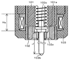
- FIG. 1 is a sectional view of a fuel injection valve according to the present invention
- FIG. 2 is an enlarged view of the vicinity of a mover.
- the fuel injection valve 1 has a housing 107 having a large diameter portion 107a, a small diameter portion 107b, and a reduced diameter portion 107c connecting between the large diameter portion 107a and the small diameter portion 107b.
- a magnetic core 101 also referred to as a fixed core, a movable iron core or simply a core
- a mover 102 also referred to as a movable core or a movable iron core
- a first rod guide 104 an urging force.
- a spring 106, a zero position spring 108, and a spring retainer 114 are accommodated.
- a nozzle 112 in which a valve seat 110 and an injection hole 111 are formed is fixed to a distal end portion of the small diameter portion 107 b of the housing 107, and a second rod guide 113 is accommodated inside the nozzle 112. Further, the valve body 103 is accommodated across the large diameter portion 107a and the small diameter portion 107b of the housing 107.
- a coil 15 and a yoke 109 are provided outside the large diameter portion 107 a of the housing 107 so as to surround the coil 105.
- the fuel injection valve 1 shown in FIG. 1 is a normally closed electromagnetic valve (electromagnetic fuel injection valve).
- the energizing spring 106 causes the seat portion 103b ( 2) is in close contact with the valve seat 110 of the nozzle 112, and the valve is closed.
- the seat portion 103 b is provided at the distal end portion of the rod portion 103 a formed on the valve body 103.
- the mover 102 is brought into close contact with the collision surface 103c side of the valve body 103 by the zero position spring 108, and there is a gap between the mover 102 and the core 101 (FIG. 2). reference).
- the collision surface 103c of the valve body 103 is provided at the end portion of the rod portion 103a opposite to the tip portion where the seat portion 103b is formed.
- the first rod guide 104 is fixed inside the large-diameter portion 107a of the housing 107 containing the valve body 103, and the first rod guide 104 is a rod so that the valve body 103 can move in the stroke direction.
- the part 103a is guided.
- the first rod guide 104 constitutes a spring seat of the zero position spring 108.
- the first rod guide 104 is disposed closer to the nozzle 112 than the mover 102 in the stroke direction of the valve body 103.
- a second rod guide 113 is provided at the distal end portion of the small-diameter portion 107b of the housing 107, and the valve body 103 can be moved in the stroke direction on the distal end side (the seat portion 103b side) of the rod portion 103a. is doing.
- the urging spring 106 is provided on the inner diameter portion of the core 101, and the urging force is adjusted at the time of assembly by the amount of pressing of the spring retainer 114 fixed to the inner diameter portion of the core 101.
- the rod portion 10a of the valve body 103 passes through the inner diameter portion of the movable element 102, and the movable element 102 can be displaced relative to the valve body 103 in the stroke direction of the valve body 103 (the axial direction of the rod portion 103a). It is assembled.
- the coil 105, the core 101, and the mover 102 constitute an electromagnet serving as a drive unit for the valve body 103.
- the urging spring 106 serving as the first urging unit urges the valve body 103 in the direction opposite to the direction of the driving force by the driving unit (the valve closing direction).
- the zero position spring 108 serving as the second urging unit urges the movable element 102 in the direction of the driving force (valve closing direction) with an urging force smaller than the urging force of the urging spring 106.
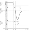
- FIG. 3 is a time chart showing this state by the amount of displacement of the movable element 102 and the valve body 103.
- a high voltage is required to input a large current.
- This high voltage is supplied by a high voltage power source that is boosted during the non-injection period and stored in the capacitor. Since this high voltage is obtained by discharging electric charges from the high-voltage power supply (discharging from the capacitor), if multiple injections are performed within a close time, the power storage performed after the discharge when the valve was opened previously May not be in time, and it may be difficult to obtain a sufficient effect.
- the voltage application sequence from the high-voltage power supply is different between the first injection and the second and subsequent injections so that the first injection consumes less power than the second injection.
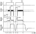
- FIG. 4 is a diagram showing a drive sequence of the fuel injection valve according to the present invention.
- the power supply time of the high-voltage power supply at the first injection is set to be shorter at the first injection by setting the supply time from the high-voltage power supply shorter at the first injection than at the second injection. It is set to be smaller.
- the first high voltage application 402 between times t 12 and t 13 is set to have a shorter application time than the second high voltage application 408 between times t 15 and t 16. As a result, less power is applied to high voltage application.
- first, voltage application from the battery voltage that has not been boosted is performed at a predetermined current value during a predetermined period t 10 to t 12 .
- the mover 102 of the fuel injection valve does not start displacement and therefore does not open.
- the fuel 404 can be used even when the current 404 from the high-voltage power supply and its power supply are small.
- the injection valve 1 can be opened.
- the inductance of the coil 105 is reduced and the rise of the current 404 is higher than the current 409 due to the high voltage application at the second injection. Become quick. As a result, even when the time for applying the high voltage 402 is short, the current 404 can be rapidly raised to supply the current necessary for valve opening.
- a reverse voltage is generated by a diode or the like to cause the current to fall at high speed as in the case of the applied voltages 411 and 412.
- the current 404 due to the high voltage application is effectively utilized, and by reducing the decrease in the current value, the magnetic attractive force that rises later than the current is increased. Can assist. By doing in this way, even if the period of the high voltage application 402 is short, valve opening can be performed more stably.
- the period of the high voltage application 408 is set longer than the high voltage application 402 at the time of the first injection. In this way, the drive current 409 can be input as fast as possible, and even if the mover continues to move after the first injection, the mover is pulled back by the magnetic attractive force and re-injected. Can be made.
- valve opening delay time from the start of energization by the pulse 406 to the start of injection becomes longer at the first injection, but this problem is caused by the fact that the valve opening delay time becomes longer in advance. It can be solved by giving it as early as possible.
- the second injection is performed after the first injection, more electric power from the high-voltage power supply can be used than the first, and therefore stable injection can be achieved even if the first and second injection intervals are shortened. Operation becomes possible.
- the power consumption of the boost power source is significantly increased even if multiple injections are performed during one stroke of the engine. Can be suppressed.
- the divided injection can be performed without using a large condenser, a cooling structure, an expensive electronic element, or the like, or the operating range of the engine capable of the divided injection can be expanded.
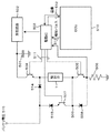
- the ECU engine control unit
- the driving IC integrated circuit for driving
- a drive IC (integrated circuit) 503 for the fuel injection valve 1 is an integrated circuit that controls a voltage application sequence to the fuel injection valve 1.
- the switching elements 504 and 505 such as FETs and transistors connected to the fuel injection valve 1 and the booster circuit 502 are controlled so as to perform voltage application and drive current control based on a drive sequence set by communication with the ECU.
- the values that can be set as the drive sequence include the battery voltage application time before applying a high voltage, its current value, the maximum current value and its holding time when a high voltage is applied, and the holding current value for maintaining the valve open state. It is good to be able to set.
- the ECU 510 may be programmed so that the ECU 510 gives a signal for changing the set value after the start of the first injection pulse to the drive IC 503 by communication, and the setting is changed before the second injection. .
- the communication as described above can be performed relatively easily.
- a capacitor 501 is connected to one terminal of the coil of the fuel injection valve 1 via a switching element 504, and a booster circuit 502 is connected to the capacitor 501.
- the other terminal of the coil of the fuel injection valve 1 is grounded via a switching element 505 and a resistor 506.
- a signal line 511 from the driving IC 503 is connected to the bases of the switching elements 504 and 505, and the switching elements 504 and 505 are individually controlled to be turned on and off by a signal from the driving IC 503.
- a communication line 512 is provided between the drive IC 503 and an ECU (engine control unit) 510 serving as a control unit.
- the ECU 510 is configured such that an injection pulse is commanded to the drive IC 503 by a signal line 513.
- a battery voltage 515 is connected between the fuel injection valve 1 and the switching element 504 via a diode 514.
- a wiring part between the diode 514 and the battery voltage 516 and a wiring part between the fuel injection valve 1 and the switching element 505 are connected via a switching element 507.
- a diode 515 is provided between the wiring portion between the diode 514 and the battery voltage 515 and the switching element 507.
- a wiring part between the switching element 507 and the fuel injection valve 1 and a wiring part between the switching element 505 and the resistor 506 are connected via a Zener diode 508.
- One base of the signal line 511 from the driving IC 503 is connected to the base of the switching element 507, and the switching element 507 is configured to be turned on and off separately from the other switching elements 504 and 505 by a signal from the driving IC 503. Has been.
- the switching elements 504 and 505 are both turned ON during the period from time t 15 to t 16 , and the voltage 408 is applied to the coil of the fuel injection valve 1. Period t 17 from the time t 16, the switching element 504 is turned OFF, so that the drive current is maintained at the second set value (413), ON of the switching element 505, and repeats means OFF.
- the fuel injection valve 1 can be driven by using the switching elements 504 and 505, but the drive current is steep as in the case where the drive current value of the fuel injection valve 1 is kept constant. There is a case where it is not desired to change the driving current, and a case where the driving current is desired to be changed abruptly as in the case where the injection control pulse is stopped. In order to control this, a switching element 507 is used.
- the fuel injection valve and the driving method thereof By using the fuel injection valve and the driving method thereof according to the present embodiment, it becomes easy to perform a plurality of fuel injections during one stroke of the engine, reducing the amount of soot generation at a high load, starting, It is possible to suppress emission of unburned hydrocarbon components by weak stratification operation during warm-up.
- the power consumption from the boost power source at the first injection is smaller than the power consumption from the boost power source at any one of the second and subsequent injections. It is good to set so that In particular, the minimum injection time interval can be set short by supplying large electric power at the timing when the injection time interval becomes short.
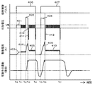
- FIG. 6 is an example of an embodiment of a method for driving a fuel injection valve according to the present invention.
- the peak value of the current value is set to be smaller at the time of the first injection than at the time of any of the second and subsequent injections.
- the injection period (t 12 to t 13 ′) of the applied voltage 603 by the boost power source at the time of the first injection is a period until the input current 607 from the boost power source reaches the target value 605 of the first peak current. It is set to be determined by.
- the potential of the shunt resistor 506 in FIG. 5 is input to the drive IC 503, and the drive IC 503 compares the set value to determine the application time of the boost power supply voltage.
- the peak current target value is set larger than that at the time of the first injection as the target value 606, so that the valve can be opened with less power consumption at the time of the first injection than at the time of the second injection.
- the first and second voltage application sequences can be made different.
- the switching elements 504, 505, and 507 are turned on and off in the same manner as in the first embodiment.
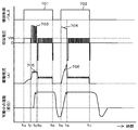
- FIG. 7 is an example of an embodiment of a method for driving a fuel injection valve according to the present invention, in which voltage application 703 from a boost power supply applied at the time of the first injection is switched to switch the voltage application for the second and subsequent times. This is an example in which the power consumption is reduced more than 704.
- the valve element can be opened while maintaining the first peak current 705 at a constant value.
- the fuel injection valve 1 can be opened while waiting for the magnetic attractive force to rise sufficiently while preventing the current supplied by the boosting power source from becoming excessive. Injection can be performed more stably.
- the current from the boosting power source can be prevented from reaching an excessive current value, even if the first injection amount is very small, it is easy to accurately measure and inject the injection amount.
- Period from the time t 10 to t 21 of FIG. 7 is the battery voltage 515 is applied to the fuel injection valve 1.
- the switching element 504 is turned off and the switching element 505 is turned on.
- the switching element 504 is ON, repeated ON the switching element 505, means OFF.
- Period t 24 from the time t 22 is the switching element 504 is turned OFF, so that the drive current is maintained at the set value is repeated ON the switching element 505, it means OFF.
- the subsequent operations are the same as those in the first or second embodiment.
Landscapes
- Engineering & Computer Science (AREA)
- Chemical & Material Sciences (AREA)
- Combustion & Propulsion (AREA)
- Mechanical Engineering (AREA)
- General Engineering & Computer Science (AREA)
- Fuel-Injection Apparatus (AREA)
Priority Applications (3)
| Application Number | Priority Date | Filing Date | Title |
|---|---|---|---|
| US13/512,406 US8899210B2 (en) | 2009-11-30 | 2010-08-16 | Drive circuit for electromagnetic fuel-injection valve |
| CN201080053746.9A CN102639860B (zh) | 2009-11-30 | 2010-08-16 | 电磁式燃料喷射阀的驱动电路 |
| EP10832919.4A EP2508743B1 (en) | 2009-11-30 | 2010-08-16 | Drive circuit for electromagnetic fuel-injection valve |
Applications Claiming Priority (2)
| Application Number | Priority Date | Filing Date | Title |
|---|---|---|---|
| JP2009270971A JP5331663B2 (ja) | 2009-11-30 | 2009-11-30 | 電磁式燃料噴射弁の駆動回路 |
| JP2009-270971 | 2009-11-30 |
Publications (1)
| Publication Number | Publication Date |
|---|---|
| WO2011065072A1 true WO2011065072A1 (ja) | 2011-06-03 |
Family
ID=44066174
Family Applications (1)
| Application Number | Title | Priority Date | Filing Date |
|---|---|---|---|
| PCT/JP2010/063805 Ceased WO2011065072A1 (ja) | 2009-11-30 | 2010-08-16 | 電磁式燃料噴射弁の駆動回路 |
Country Status (5)
| Country | Link |
|---|---|
| US (1) | US8899210B2 (enExample) |
| EP (1) | EP2508743B1 (enExample) |
| JP (1) | JP5331663B2 (enExample) |
| CN (1) | CN102639860B (enExample) |
| WO (1) | WO2011065072A1 (enExample) |
Cited By (1)
| Publication number | Priority date | Publication date | Assignee | Title |
|---|---|---|---|---|
| EP2538061A3 (en) * | 2011-06-20 | 2014-10-15 | Hitachi Automotive Systems, Ltd. | Fuel injection device |
Families Citing this family (23)
| Publication number | Priority date | Publication date | Assignee | Title |
|---|---|---|---|---|
| DE102011005672B4 (de) * | 2011-03-17 | 2019-07-11 | Continental Automotive Gmbh | Verfahren, Vorrichtung und Computerprogramm zur elektrischen Ansteuerung eines Aktuators zur Bestimmung des Zeitpunkts eines Ankeranschlags |
| WO2013191267A1 (ja) * | 2012-06-21 | 2013-12-27 | 日立オートモティブシステムズ株式会社 | 内燃機関の制御装置 |
| DE102012211994B4 (de) * | 2012-07-10 | 2024-08-08 | Vitesco Technologies GmbH | Steuergerät zur Ansteuerung zumindest einen Kraftstoffeinspritzventils und Schaltungsanordnung mit einem solchen Steuergerät |
| DE102012213883B4 (de) * | 2012-08-06 | 2015-03-26 | Continental Automotive Gmbh | Gleichstellung des Stromverlaufs durch einen Kraftstoffinjektor für verschiedene Teileinspritzvorgänge einer Mehrfacheinspritzung |
| JP5849975B2 (ja) * | 2013-02-25 | 2016-02-03 | 株式会社デンソー | 燃料噴射制御装置および燃料噴射システム |
| JP5815590B2 (ja) * | 2013-04-05 | 2015-11-17 | 本田技研工業株式会社 | 電磁弁駆動装置 |
| JP6130280B2 (ja) * | 2013-09-25 | 2017-05-17 | 日立オートモティブシステムズ株式会社 | 燃料噴射装置の駆動装置 |
| JP2015102052A (ja) * | 2013-11-26 | 2015-06-04 | 株式会社デンソー | 燃料噴射制御装置 |
| EP2918816B1 (en) * | 2014-03-14 | 2017-09-06 | Continental Automotive GmbH | Fuel injector |
| GB2524259A (en) * | 2014-03-17 | 2015-09-23 | Gm Global Tech Operations Inc | Method of operating a fuel injector |
| GB2534172A (en) * | 2015-01-15 | 2016-07-20 | Gm Global Tech Operations Llc | Method of energizing a solenoidal fuel injector for an internal combustion engine |
| DE102015219383B3 (de) | 2015-10-07 | 2017-02-09 | Continental Automotive Gmbh | Bestimmung eines Zeitpunktes, zu welchem sich ein Kraftstoffinjektor in einem vorbestimmten Zustand befindet |
| JP6557608B2 (ja) * | 2016-01-22 | 2019-08-07 | 日立オートモティブシステムズ株式会社 | 燃料噴射装置の制御装置 |
| US10060399B2 (en) * | 2016-04-22 | 2018-08-28 | GM Global Technology Operations LLC | Method and apparatus for optimum drive signal control of an electromagnetically-activated actuator |
| US10883434B2 (en) * | 2016-08-26 | 2021-01-05 | Hitachi Automotive Systems, Ltd. | Control device for fuel injection device |
| JP6720935B2 (ja) * | 2017-07-28 | 2020-07-08 | 株式会社Soken | 燃料噴射制御装置及び燃料噴射制御方法 |
| JP6939472B2 (ja) | 2017-11-27 | 2021-09-22 | トヨタ自動車株式会社 | 内燃機関の制御装置 |
| WO2019181291A1 (ja) * | 2018-03-22 | 2019-09-26 | 日立オートモティブシステムズ株式会社 | 内燃機関制御装置 |
| CN108656741B (zh) * | 2018-05-21 | 2020-06-02 | 苏州华兴源创科技股份有限公司 | 一种利用电磁阀控制的喷墨打点装置和方法 |
| JP6642653B2 (ja) * | 2018-08-24 | 2020-02-12 | 株式会社デンソー | 燃料噴射制御装置および燃料噴射システム |
| JP7256772B2 (ja) * | 2020-03-30 | 2023-04-12 | 日立Astemo株式会社 | 燃料噴射装置の制御装置、制御方法及びプログラム |
| KR102514687B1 (ko) * | 2021-05-11 | 2023-03-27 | 주식회사 현대케피코 | 지디아이 엔진 인젝터의 부스트 전압 제어 장치 및 방법 |
| CN115628145B (zh) * | 2022-10-24 | 2023-04-14 | 南京工业大学 | 一种气助雾化喷嘴的电流型驱动电路及驱动控制方法 |
Citations (3)
| Publication number | Priority date | Publication date | Assignee | Title |
|---|---|---|---|---|
| JPH05296120A (ja) | 1992-04-20 | 1993-11-09 | Mitsubishi Heavy Ind Ltd | 電磁式ユニットインジェクタ |
| JP2008280876A (ja) | 2007-05-09 | 2008-11-20 | Hitachi Ltd | 電磁式燃料噴射弁の制御回路 |
| JP2009121482A (ja) * | 2007-11-15 | 2009-06-04 | Delphi Technologies Inc | グリッチ検出器とグリッチ事象を検出する方法 |
Family Cites Families (11)
| Publication number | Priority date | Publication date | Assignee | Title |
|---|---|---|---|---|
| US4774624A (en) * | 1987-07-06 | 1988-09-27 | Motorola, Inc. | Boost voltage power supply for vehicle control system |
| DE4411789C2 (de) * | 1994-04-06 | 2003-12-11 | Bosch Gmbh Robert | Verfahren und Vorrichtung zur Steuerung der Kraftstoffzumessung in eine Brennkraftmaschine |
| JPH1162677A (ja) * | 1997-08-08 | 1999-03-05 | Denso Corp | 電磁弁駆動装置 |
| DE19813138A1 (de) * | 1998-03-25 | 1999-09-30 | Bosch Gmbh Robert | Verfahren und Vorrichtung zur Ansteuerung eines elektromagnetischen Verbrauchers |
| JP2000130230A (ja) * | 1998-10-23 | 2000-05-09 | Isuzu Motors Ltd | エンジンの燃料噴射制御装置 |
| JP3671785B2 (ja) * | 1999-12-15 | 2005-07-13 | 株式会社日立製作所 | 筒内噴射型内燃機関の燃料噴射装置 |
| JP5055050B2 (ja) * | 2006-10-10 | 2012-10-24 | 日立オートモティブシステムズ株式会社 | 内燃機関制御装置 |
| DE102006060311A1 (de) | 2006-12-20 | 2008-06-26 | Robert Bosch Gmbh | Verfahren zum Betrieb eines Einspritzventils |
| JP4925976B2 (ja) * | 2007-08-29 | 2012-05-09 | 株式会社ケーヒン | 内燃機関制御装置 |
| US7878177B2 (en) * | 2007-10-23 | 2011-02-01 | Ford Global Technologies, Llc | Internal combustion engine having common power source for ion current sensing and fuel injectors |
| JP4776651B2 (ja) * | 2008-03-28 | 2011-09-21 | 日立オートモティブシステムズ株式会社 | 内燃機関制御装置 |
-
2009
- 2009-11-30 JP JP2009270971A patent/JP5331663B2/ja not_active Expired - Fee Related
-
2010
- 2010-08-16 CN CN201080053746.9A patent/CN102639860B/zh not_active Expired - Fee Related
- 2010-08-16 EP EP10832919.4A patent/EP2508743B1/en not_active Not-in-force
- 2010-08-16 WO PCT/JP2010/063805 patent/WO2011065072A1/ja not_active Ceased
- 2010-08-16 US US13/512,406 patent/US8899210B2/en not_active Expired - Fee Related
Patent Citations (3)
| Publication number | Priority date | Publication date | Assignee | Title |
|---|---|---|---|---|
| JPH05296120A (ja) | 1992-04-20 | 1993-11-09 | Mitsubishi Heavy Ind Ltd | 電磁式ユニットインジェクタ |
| JP2008280876A (ja) | 2007-05-09 | 2008-11-20 | Hitachi Ltd | 電磁式燃料噴射弁の制御回路 |
| JP2009121482A (ja) * | 2007-11-15 | 2009-06-04 | Delphi Technologies Inc | グリッチ検出器とグリッチ事象を検出する方法 |
Cited By (4)
| Publication number | Priority date | Publication date | Assignee | Title |
|---|---|---|---|---|
| EP2538061A3 (en) * | 2011-06-20 | 2014-10-15 | Hitachi Automotive Systems, Ltd. | Fuel injection device |
| US9347393B2 (en) | 2011-06-20 | 2016-05-24 | Hitachi Automotive Systems, Ltd. | Fuel injection device |
| US10082117B2 (en) | 2011-06-20 | 2018-09-25 | Hitachi Automotive Systems, Ltd. | Fuel injection device |
| US10859047B2 (en) | 2011-06-20 | 2020-12-08 | Hitachi Automotive Systems, Ltd. | Fuel injection device |
Also Published As
| Publication number | Publication date |
|---|---|
| CN102639860A (zh) | 2012-08-15 |
| EP2508743B1 (en) | 2017-08-16 |
| US8899210B2 (en) | 2014-12-02 |
| EP2508743A1 (en) | 2012-10-10 |
| JP2011112008A (ja) | 2011-06-09 |
| JP5331663B2 (ja) | 2013-10-30 |
| US20120234299A1 (en) | 2012-09-20 |
| EP2508743A4 (en) | 2015-10-21 |
| CN102639860B (zh) | 2015-04-15 |
Similar Documents
| Publication | Publication Date | Title |
|---|---|---|
| JP5331663B2 (ja) | 電磁式燃料噴射弁の駆動回路 | |
| JP4691523B2 (ja) | 電磁式燃料噴射弁の制御回路 | |
| JP5492806B2 (ja) | 電磁式燃料噴射弁の駆動装置 | |
| US6332453B1 (en) | Electromagnetic system fuel injection apparatus an internal combustion engine having an electromagnetic system fuel injection apparatus, and a drive circuit of an electromagnetic system fuel injection apparatus | |
| CN103069138B (zh) | 燃料喷射装置的驱动装置 | |
| US8020533B2 (en) | Fuel injection device, fuel injection control device, and control method of fuel injection device | |
| JP6414022B2 (ja) | 燃料噴射制御装置と燃料噴射システム | |
| JP2014092089A (ja) | 燃料噴射制御装置および燃料噴射システム | |
| JP7177458B2 (ja) | 燃料噴射装置を制御する制御装置 | |
| JP6561184B2 (ja) | 燃料噴射装置の駆動装置 | |
| JP5865409B2 (ja) | 電磁式燃料噴射弁の駆動装置 | |
| JP2018031294A (ja) | 電磁弁駆動装置 | |
| JP4695544B2 (ja) | 燃料噴射装置の制御方法 | |
| JP2001165014A (ja) | 燃料噴射装置 | |
| JP4695543B2 (ja) | 燃料噴射装置及び燃料噴射制御装置 | |
| JP3094020B2 (ja) | 電磁付勢部材を励起する切換装置および同装置の動作方法 | |
| JP7047139B2 (ja) | 燃料噴射弁を制御する制御装置及びプログラム | |
| JP2019002379A (ja) | 電磁弁駆動装置 | |
| JP2014156867A (ja) | 電磁弁装置の駆動装置 | |
| JP2004132381A (ja) | 燃料噴射装置 |
Legal Events
| Date | Code | Title | Description |
|---|---|---|---|
| WWE | Wipo information: entry into national phase |
Ref document number: 201080053746.9 Country of ref document: CN |
|
| 121 | Ep: the epo has been informed by wipo that ep was designated in this application |
Ref document number: 10832919 Country of ref document: EP Kind code of ref document: A1 |
|
| WWE | Wipo information: entry into national phase |
Ref document number: 13512406 Country of ref document: US |
|
| NENP | Non-entry into the national phase |
Ref country code: DE |
|
| REEP | Request for entry into the european phase |
Ref document number: 2010832919 Country of ref document: EP |
|
| WWE | Wipo information: entry into national phase |
Ref document number: 2010832919 Country of ref document: EP |