WO2011055696A1 - Système de communication, micro station de base et procédé de communication - Google Patents
Système de communication, micro station de base et procédé de communication Download PDFInfo
- Publication number
- WO2011055696A1 WO2011055696A1 PCT/JP2010/069339 JP2010069339W WO2011055696A1 WO 2011055696 A1 WO2011055696 A1 WO 2011055696A1 JP 2010069339 W JP2010069339 W JP 2010069339W WO 2011055696 A1 WO2011055696 A1 WO 2011055696A1
- Authority
- WO
- WIPO (PCT)
- Prior art keywords
- base station
- communication
- base stations
- connection
- radio
- Prior art date
Links
- 238000004891 communication Methods 0.000 title claims abstract description 491
- 238000000034 method Methods 0.000 title claims description 70
- 238000010295 mobile communication Methods 0.000 claims abstract description 39
- 230000002093 peripheral effect Effects 0.000 claims abstract description 29
- 238000009434 installation Methods 0.000 claims description 12
- 238000012545 processing Methods 0.000 description 27
- 230000004044 response Effects 0.000 description 22
- 238000010586 diagram Methods 0.000 description 10
- 230000006870 function Effects 0.000 description 4
- 239000002699 waste material Substances 0.000 description 3
- 230000004308 accommodation Effects 0.000 description 2
- 230000000694 effects Effects 0.000 description 2
- 230000007774 longterm Effects 0.000 description 2
- 230000003287 optical effect Effects 0.000 description 2
- 238000013459 approach Methods 0.000 description 1
- 230000005540 biological transmission Effects 0.000 description 1
- 238000010276 construction Methods 0.000 description 1
- 238000005516 engineering process Methods 0.000 description 1
- 238000005259 measurement Methods 0.000 description 1
- 238000012986 modification Methods 0.000 description 1
- 230000004048 modification Effects 0.000 description 1
- 239000013307 optical fiber Substances 0.000 description 1
- 230000005641 tunneling Effects 0.000 description 1
Images


Classifications
-
- H—ELECTRICITY
- H04—ELECTRIC COMMUNICATION TECHNIQUE
- H04W—WIRELESS COMMUNICATION NETWORKS
- H04W92/00—Interfaces specially adapted for wireless communication networks
- H04W92/16—Interfaces between hierarchically similar devices
- H04W92/20—Interfaces between hierarchically similar devices between access points
-
- H—ELECTRICITY
- H04—ELECTRIC COMMUNICATION TECHNIQUE
- H04W—WIRELESS COMMUNICATION NETWORKS
- H04W36/00—Hand-off or reselection arrangements
- H04W36/0005—Control or signalling for completing the hand-off
- H04W36/0055—Transmission or use of information for re-establishing the radio link
- H04W36/0064—Transmission or use of information for re-establishing the radio link of control information between different access points
-
- H—ELECTRICITY
- H04—ELECTRIC COMMUNICATION TECHNIQUE
- H04W—WIRELESS COMMUNICATION NETWORKS
- H04W84/00—Network topologies
- H04W84/02—Hierarchically pre-organised networks, e.g. paging networks, cellular networks, WLAN [Wireless Local Area Network] or WLL [Wireless Local Loop]
- H04W84/04—Large scale networks; Deep hierarchical networks
- H04W84/042—Public Land Mobile systems, e.g. cellular systems
-
- H—ELECTRICITY
- H04—ELECTRIC COMMUNICATION TECHNIQUE
- H04W—WIRELESS COMMUNICATION NETWORKS
- H04W36/00—Hand-off or reselection arrangements
- H04W36/0005—Control or signalling for completing the hand-off
- H04W36/0055—Transmission or use of information for re-establishing the radio link
-
- H—ELECTRICITY
- H04—ELECTRIC COMMUNICATION TECHNIQUE
- H04W—WIRELESS COMMUNICATION NETWORKS
- H04W72/00—Local resource management
- H04W72/04—Wireless resource allocation
-
- H—ELECTRICITY
- H04—ELECTRIC COMMUNICATION TECHNIQUE
- H04W—WIRELESS COMMUNICATION NETWORKS
- H04W84/00—Network topologies
- H04W84/02—Hierarchically pre-organised networks, e.g. paging networks, cellular networks, WLAN [Wireless Local Area Network] or WLL [Wireless Local Loop]
- H04W84/04—Large scale networks; Deep hierarchical networks
- H04W84/042—Public Land Mobile systems, e.g. cellular systems
- H04W84/045—Public Land Mobile systems, e.g. cellular systems using private Base Stations, e.g. femto Base Stations, home Node B
Definitions
- the present invention relates to a communication system, a small base station, and a communication method.
- Microcell base stations radio wave insensitive areas where radio waves from outdoor base stations (hereinafter referred to as “macrocell base stations”) are difficult to reach (or do not reach), Communication via mobile phone becomes impossible. Therefore, construction of a communication system using a small base station is being studied in order to enable communication using a mobile phone even in a radio wave insensitive area.
- a small base station (hereinafter referred to as a “femtocell base station”) having a very small cell (femtocell) with a radius of several meters to several tens of meters as a communication area is installed in a radio wave insensitive area.
- the femtocell base station is connected to a mobile communication network of a mobile phone operator via a wired communication line. Accordingly, the mobile phone in the radio wave insensitive area is connected to the mobile communication network via the femtocell base station and the wired communication line. As a result, communication using a mobile phone is possible even in a radio wave insensitive area.
- Patent Document 1 discloses a communication system including a wireless base station installed in a subscriber's house for optical communication.
- a signal from a mobile phone used in a subscriber premises is transmitted from a wireless base station in the premises to an accommodation station via an optical communication cable, and the accommodation station transmits an IP network, a general telephone switching network, or a mobile It is transmitted to various networks such as a communication exchange network.
- LTE Long Term Evolution
- Adjacent macro cell base stations communicate information about the used frequency band, information about the movement operation of the mobile terminal, and the like via the X2 interface. As a result, radio wave interference between adjacent macro cells is suppressed, and rapid inter-cell movement is realized.
- moving of a mobile terminal means not only handover but also through which base station when an idle mobile terminal starts communication in the future, that is, when a call or data communication is started. It means to choose whether to do.
- femtocell base station Home eNodeB
- a communication connection using the X2 interface has not been established between the macrocell base station located in the vicinity and other femtocell base stations located in the vicinity. Therefore, since information regarding the used frequency band cannot be communicated with each other via the X2 interface, when the used frequency band overlaps between adjacent cells, radio wave interference between adjacent cells increases. In addition, since information regarding the movement operation cannot be communicated with each other via the X2 interface, it is difficult to quickly move between cells.
- the present invention has been made in view of such circumstances, and a femtocell base station can also suppress radio wave interference between adjacent cells, and can realize rapid inter-cell movement, An object is to obtain a small base station and a communication method.
- a communication system includes a mobile communication network, a fixed communication network connected to the mobile communication network, and a plurality of radio base stations capable of communicating with a mobile terminal by wireless communication.
- the wireless base station includes a first base station connected to the mobile communication network and a second base station connected to the fixed communication network via a wired communication line, There is a predetermined interval between the second base station and a peripheral base station including the first base station and / or the other second base station located around the second base station.
- a communication connection using the logical interface is established.
- a communication connection using a predetermined logical interface is established between the second base station and the peripheral base station. Accordingly, since the second base station and the neighboring base station can communicate information on the used frequency band with each other via the logical interface, by setting the used frequency band so that they do not overlap each other, Duplication of the used frequency band can be avoided. As a result, it is possible to suppress radio wave interference between adjacent cells. In addition, since the second base station and the neighboring base stations can communicate information on the movement operation with each other via the logical interface, it is possible to quickly move between cells.
- a communication system is characterized in that, in the communication system according to the first aspect, a logical interface between a base station and a base station is used as the predetermined logical interface. is there.
- the “logical interface between the base station and the base station” includes the X2 interface in LTE.
- the second base station and the peripheral base station can be directly logically connected using the logical interface between the base station and the base station, communication such as MME is possible. Information can be communicated between the second base station and the neighboring base stations without changing the management device.
- the communication system according to a third aspect of the present invention is the communication system according to the second aspect, in particular, the second base station searches for the peripheral base station and responds to the search with the peripheral base station. Is requested to establish the communication connection, and the communication connection is established with the neighboring base station responding to the request.
- the second base station searches for a neighboring base station, makes a request for establishing a communication connection to the neighboring base station responding to the search, and responds to the request.
- a communication connection is established with the responding neighboring base station. Since the second base station searches for the neighboring base stations by itself, it is not necessary to prepare a management server that holds the position information of the radio base station, so that the configuration of the communication system can be simplified.
- the second base station setting information and the like can be notified from the second base station to the neighboring base station when a communication connection establishment request is made, and the neighboring base station setting information is sent when responding to the request. Etc. can be notified from the neighboring base station to the second base station. By notifying each other of the setting information, a communication connection can be reliably established.
- a communication system in the communication system according to the second aspect, further includes a management server that holds position information of the radio base station, and the second base station Information on the base station is acquired from the management server, the establishment of the communication connection is requested to the peripheral base station that has acquired the information from the management server, and the base station responding to the request And establishing the communication connection.
- the second base station acquires information on the neighboring base station from the management server, and requests for establishment of a communication connection to the neighboring base station that has obtained the information from the management server. To establish a communication connection with the neighboring base station responding to the request.
- the second base station setting information and the like can be notified from the second base station to the neighboring base station when a communication connection establishment request is made, and the neighboring base station setting information is sent when responding to the request. Etc. can be notified from the neighboring base station to the second base station. By notifying each other of the setting information, a communication connection can be reliably established.
- the communication system according to the fifth aspect of the present invention is the communication system according to the first aspect, in particular, between the base station and the base station using a logical interface between the base station and the upper node as the predetermined logical interface.
- a logical interface is used.
- the “logical interface between the base station and the upper node” includes the S1 interface in LTE. Further, the “logical interface between the base station and the base station” includes the X2 interface in LTE.
- the logical interface between the base station and the base station is tunneled to the logical interface between the base station and the upper node, whereby the second base station and the peripheral base station are logically connected. can do.
- the second base station and the neighboring base station can be logically connected without adding a new port for establishing the logical interface between the base station and the base station separately from the logical interface between the base station and the upper node. It becomes possible to connect.
- a communication system is the communication system according to the fifth aspect, in particular, connected to the second base station using the logical interface between the base station and the upper node, and It further comprises a communication management device that collects information about the station.
- the communication management device can collect information on the neighboring base stations of the second base station from other communication management devices and the like. Since the communication management apparatus collects information related to the neighboring base stations, it is not necessary to prepare a management server that holds the position information of the radio base station, so that the configuration of the communication system can be simplified.
- the communication system according to a seventh aspect of the present invention is the communication system according to the sixth aspect, in particular, the second base station acquires information on the neighboring base station from the communication management device, and the communication management Request the establishment of the communication connection to the neighboring base station that has acquired the information from the device via the communication management device, and establish the communication connection with the neighboring base station that responded to the request. It is characterized by doing.
- the second base station setting information and the like can be notified from the second base station to the neighboring base stations, and a response to the request
- setting information and the like of the neighboring base station can be notified from the neighboring base station to the second base station.
- a small base station includes a mobile communication network, a fixed communication network connected to the mobile communication network, a plurality of radio base stations capable of communicating with a mobile terminal by wireless communication,
- a small base station used in a communication system comprising: a first base station connected to the mobile communication network; and a wireless communication base station connected to the fixed communication network via a wired communication line.
- the second base station as the small base station is included, and the first base station and / or other base stations located around the second base station and the second base station are included.
- a communication connection using a predetermined logical interface is established between the peripheral base station including the second base station.
- a communication connection using a predetermined logical interface is established between the second base station and the peripheral base station. Accordingly, since the second base station and the neighboring base station can communicate information on the used frequency band with each other via the logical interface, by setting the used frequency band so that they do not overlap each other, Duplication of the used frequency band can be avoided. As a result, it is possible to suppress radio wave interference between adjacent cells. In addition, since the second base station and the neighboring base stations can communicate information on the movement operation with each other via the logical interface, it is possible to quickly move between cells.
- a communication method includes a mobile communication network, a fixed communication network connected to the mobile communication network, and a plurality of radio base stations capable of communicating with a mobile terminal by radio communication.
- the wireless base station includes a first base station connected to the mobile communication network and a second base station connected to the fixed communication network via a wired communication line. And a base station including the first base station and / or the other second base station located around the second base station.
- a communication connection using a predetermined logical interface is established, and the second base station communicates with the neighboring base stations via the communication connection. It is.
- a communication connection using a predetermined logical interface is established between the second base station and the peripheral base station. Accordingly, since the second base station and the neighboring base station can communicate information on the used frequency band with each other via the logical interface, by setting the used frequency band so that they do not overlap each other, Duplication of the used frequency band can be avoided. As a result, it is possible to suppress radio wave interference between adjacent cells. In addition, since the second base station and the neighboring base stations can communicate information on the movement operation with each other via the logical interface, it is possible to quickly move between cells.
- a communication system is the communication system according to the second aspect, and further includes a relay device connected between the mobile communication network and the fixed communication network.
- a base station is connected to the mobile communication network via the fixed communication network and the relay device, and the relay device and the second base station are connected between the relay device and the first base station.
- the communication system by using the logical interface between the base station and the base station using the logical interface between the base station and the upper node between the relay device and the second base station.
- the communication connection using the logical interface between the base station and the base station can be established as if between the first base station and the second base station.
- a communication connection using a logical interface between the base station and the base station can be established between the first base station, the relay device, and the second base station in a pseudo manner.
- the communication system can communicate with a mobile terminal by wireless communication and can establish a communication connection using a predetermined logical interface with another wireless base station.
- a connection indicating an instruction to perform connection establishment processing for establishing the communication connection with the target base station when the target base station which is the radio base station to newly establish the communication connection is recognized.
- An establishment instruction is notified to a plurality of the radio base stations other than the target base station, and the radio base station is notified of the connection establishment instruction from the communication control device. After the connection establishment process, it is determined whether to maintain the established state of the communication connection between the target base station, when it is determined not to be maintained, cutting the communication connection.
- a radio base station is newly installed, and a communication connection using a predetermined logical interface is established between the radio base station and another radio base station.
- a predetermined logical interface is established between the radio base station and another radio base station.
- the target base station is connected to a mobile communication network via a fixed communication network, and the communication control device Notifies the connection establishment instruction to all the wireless base stations other than the target base station.
- the communication system According to the communication system according to the twelfth aspect of the present invention, it is not necessary to select a radio base station that is a notification destination of a connection establishment instruction, and the process of notifying the connection establishment instruction can be simplified.
- the target base station is connected to a mobile communication network via a fixed communication network, and the communication control device Notifies the connection establishment instruction to the wireless base stations arranged around the target base station among the wireless base stations.
- communication connection establishment processing using a predetermined logical interface is achieved by a configuration in which a connection establishment instruction is notified only to radio base stations arranged around the target base station. Can be performed more efficiently.
- the radio base station is notified of the connection establishment instruction from the communication control apparatus. After performing the connection establishment process, if the predetermined logical interface established with the target base station is not used for a predetermined period, it is determined that the communication connection establishment state should not be maintained. .
- the communication system according to the fourteenth aspect of the present invention can appropriately determine whether or not a predetermined logical interface should be maintained.
- the wireless base station performs the connection establishment process by receiving the connection establishment instruction from the communication control apparatus, and then uses the predetermined logical interface established with the target base station.
- the amount of data transmitted / received during the period is equal to or smaller than a predetermined value, it is determined that the communication connection establishment state should not be maintained.
- the wireless base station transmits the predetermined data to the target base station after receiving the connection establishment instruction from the communication control apparatus and performing the connection establishment process, and the target base for the predetermined data If the response time of the station is greater than or equal to a predetermined value, it is determined that the communication connection establishment state should not be maintained.
- the communication system can communicate with a mobile terminal by wireless communication and can establish a communication connection using a predetermined logical interface with another wireless base station.
- the communication control device includes the other radio base stations.
- the communication connection establishment process using a predetermined logical interface is configured by notifying the connection establishment instruction only to the radio base stations arranged around the target base station. Can be performed more efficiently.
- the communication control device indicates installation locations of the plurality of radio base stations including the target base station. Based on the information, the radio base station to be notified of the connection establishment instruction is selected from the radio base stations.
- the communication system it is possible to appropriately select a radio base station to which a connection establishment instruction is to be notified, by using a configuration that uses information indicating the installation location of the radio base station.
- the mobile terminal performs a movement operation between the radio base stations.
- Information, information indicating interference received by the radio base station, and load information of the radio base station are transmitted and received between the radio base stations via the predetermined logical interface.
- radio wave interference between adjacent femtocells can be suppressed, and quick and appropriate inter-cell movement can be realized.
- the communication control apparatus can store information of a plurality of radio base stations that can establish communication connections with other radio base stations using a predetermined logical interface. Yes, when the communication control apparatus is capable of communicating with the plurality of radio base stations, and recognizes the target base station that is the radio base station to newly establish the communication connection with the other radio base stations.
- a connection establishment instruction indicating an instruction to perform a connection establishment process for establishing the communication connection with the target base station is sent to the plurality of radio base stations other than the target base station, and the radio base station Whether the communication connection establishment state between the radio base station and the target base station should be maintained after the connection establishment instruction is received and the connection establishment process is performed. Or it is determined, if it is determined not to be maintained, it performs control to disconnect the communication connection.
- a radio base station is newly installed, and a communication connection using a predetermined logical interface is established between the radio base station and another radio base station.
- establishment it is not necessary for a person to manually execute the establishment process, and labor and cost can be reduced.
- the communication method according to the nineteenth aspect of the present invention is capable of communicating with a mobile terminal by wireless communication and can establish a communication connection using a predetermined logical interface with another wireless base station.
- a communication method in a communication system comprising a plurality of radio base stations and a communication control apparatus capable of storing information on the plurality of radio base stations and capable of communicating with the plurality of radio base stations, the communication control apparatus Establishes a connection for establishing the communication connection with the target base station when recognizing the target base station which is the radio base station to newly establish the communication connection with the other radio base station.
- a radio base station is newly installed, and a communication connection using a predetermined logical interface is established between the radio base station and another radio base station.
- a predetermined logical interface is established between the radio base station and another radio base station.
- the present invention with respect to the femtocell base station, it is possible to suppress radio wave interference between adjacent cells and realize rapid movement between cells.
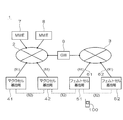
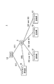
- FIG. 1 is a diagram showing an overall configuration of a communication system 1 according to the first embodiment of the present invention.
- Macro cell base stations (eNodeB) 41 and 42 are connected to the mobile communication network 2.
- Femtocell base stations (Home eNodeB) 51 and 52 are connected to the fixed communication network 3 via wired communication lines 61 and 62 such as optical fibers.
- the fixed communication network 3 is connected to the mobile communication network 2 via a gateway 9.
- MME Mobility Management Entity
- the mobile communication network 2 is connected to an MME 8 as an upper node of the femtocell base stations 51 and 52.
- the MME 7 functions as a communication management apparatus related to communication via the macrocell base stations 41 and 42, and executes various processes such as session setting and release, and movement operation control.
- the MME 8 functions as a communication management apparatus related to communication via the femtocell base stations 51 and 52, and executes various processes such as session setting and release, and control of movement operation.
- the macrocell base stations 41 and 42 are logically connected to the MME 7 via a logical interface (S1 interface in LTE (Long Term Evolution)) between the base station and the upper node.
- the femtocell base stations 51 and 52 are logically connected to the MME 8 via a logical interface (S1 interface) between the base station and the upper node.
- the macro cell base stations 41 and 42 are logically connected to each other via a logical interface between the base station and the base station (X2 interface in LTE).
- the macro cell base station 42 and the femto cell base station 52 are assumed to be peripheral base stations of the femto cell base station 51. That is, the femtocell that is the communication area of the femtocell base station 51, the macrocell that is the communication area of the macrocell base station 42, and the femtocell that is the communication area of the femtocell base station 52 are overlapped or close to each other. Therefore, it is assumed that radio waves transmitted and received at the macrocell base station 42 and the femtocell base station 52 can interfere with radio waves transmitted and received at the femtocell base station 51.
- the mobile terminal 100 such as a mobile phone communicating with the femtocell base station 51 moves, the macrocell of the macrocell base station 42 and the femtocell of the femtocell base station 52 It can be the target of handover from 51 femtocells.
- a femtocell base station 51 is logically connected to a macrocell base station 42 and a femtocell base station 52, which are neighboring base stations, via a logical interface (X2 interface) between the base station and the base station. ing. That is, a communication connection using the X2 interface is established between the femtocell base station 51 and the peripheral base station.
- X2 interface logical interface
- FIG. 2 is a diagram showing a processing sequence for establishing a communication connection when the femtocell base station 51 is newly established.
- the femtocell base station 51 searches for neighboring base stations. Specifically, the femtocell base station 51 uses the femtocell base station 51 together with its own identification information such as a base station ID, the search signal M101 for requesting a response when the received radio wave intensity is equal to or higher than a predetermined threshold.
- the broadcast transmission is performed wirelessly toward the periphery of 51.
- the search signal M101 is received by the macrocell base stations 41 and 42 and the femtocell base station 52.
- the macrocell base stations 41 and 42 and the femtocell base station 52 measure the received radio wave intensity of the search signal M101 and determine whether or not a response to the femtocell base station 51 is necessary.
- the received radio wave intensity of the search signal M101 received by the macro cell base station 42 and the femto cell base station 52 that are neighboring base stations is equal to or higher than the threshold value, and is received by the macro cell base station 41 that is not the neighboring base station.
- the received radio wave intensity of the search signal M101 is less than the threshold value.
- the macrocell base station 42 and the femtocell base station 52 return a response signal M102 indicating that the search signal M101 has been received to the femtocell base station 51 together with its own identification information such as a base station ID.
- the response signal M102 may be returned by either wired communication or wireless communication.
- the macro cell base station 41 does not return a response signal M102 to the femtocell base station 51.
- the femtocell base station 51 stores the information received from the macrocell base station 42 and the femtocell base station 52 and then sends a request signal M103 for requesting establishment of a communication connection to the port number used for the X2 interface, It is transmitted to the macrocell base station 42 and the femtocell base station 52 together with its own setting information such as position information.
- the request signal M103 may be transmitted by either wired communication or wireless communication.
- the macrocell base station 42 and the femtocell base station 52 that have received the request signal M103 send a response signal M104 to the request for establishing a communication connection together with its own setting information such as a port number and position information used for the X2 interface.
- the response signal M104 may be returned by either wired communication or wireless communication.
- the X2 interface is established between the femto cell base station 51 and the macro cell base station 42 and the femto cell base station 52.
- a communication connection using is established.
- the communication connection may be either wired or wireless.
- the femtocell base station 51, the macrocell base station 42, and the femtocell base station 52 communicate their own setting information M105 such as a frequency band to be used via the communication connection. Further, when the mobile terminal 100 needs to move, information about the moving operation is communicated with each other via the communication connection.
- a predetermined logical interface is used between the femtocell base station 51 and the peripheral base stations (the macrocell base station 42 and the femtocell base station 52).
- a communication connection has been established. Therefore, since the femtocell base station 51 and the neighboring base stations can communicate information on the used frequency band with each other via the logical interface, by setting the used frequency band so that they do not overlap each other, Duplication of the used frequency band can be avoided. As a result, it is possible to suppress radio wave interference between adjacent cells.
- the femtocell base station 51 and the neighboring base stations can communicate information on the movement operation with each other via the logical interface, the cell can be compared with the case where the information is communicated via the MME 7, 8 or the like. It is possible to quickly move between.
- the communication management device such as the MME 7 or 8 is used. It is possible to perform information communication between the femtocell base station 51 and the neighboring base stations without changing the above.
- the femtocell base station 51 searches for neighboring base stations, requests the neighboring base stations that respond to the search to establish a communication connection, A communication connection is established with a neighboring base station that responds to the request. Since the femtocell base station 51 searches for neighboring base stations by itself, it is not necessary to prepare the management server 10 (see FIG. 3) that holds the position information of the radio base station, so the configuration of the communication system 1 can be simplified. It becomes possible to plan.
- the setting information of the femtocell base station 51 can be notified from the femtocell base station 51 to the neighboring base station at the time of requesting establishment of the communication connection, and the setting information of the neighboring base station at the time of responding to the request. Etc. can be notified from the neighboring base station to the femtocell base station 51. By notifying each other of the setting information, a communication connection can be reliably established.
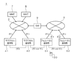
- FIG. 3 is a diagram showing an overall configuration of the communication system 1 according to the second embodiment of the present invention.
- a management server 10 such as an HLR (Home Location Register) is added to the configuration shown in FIG. 1, and other configurations are the same as those in FIG.
- the management server 10 is connected to the fixed communication network 3.
- the management server 10 does not necessarily have to be connected to the fixed communication network 3, and may be installed at any location in the communication system 1.
- the management server 10 associates position information regarding the installation location of existing radio base stations (the macro cell base stations 41 and 42 and the femto cell base station 52 in the example of the present embodiment) with identification information such as a base station ID. Is remembered.
- FIG. 4 is a diagram showing a processing sequence for establishing a communication connection when the femtocell base station 51 is newly established.
- the femtocell base station 51 When the femtocell base station 51 is connected to the fixed communication network 3, the femtocell base station 51 first sends a request signal M201 for requesting registration of the own station together with its own identification information such as base station ID and position information. And transmitted to the management server 10 via the fixed communication network 3.
- the management server 10 that has received the request signal M201 registers the femtocell base station 51, and identifies the peripheral base stations of the femtocell base station 51 based on the position information of the femtocell base station 51.
- the management server 10 identifies the macro cell base station 42 and the femto cell base station 52 as the peripheral base stations of the femto cell base station 51.
- the management server 10 transmits a registration completion notification M202 indicating that the registration of the femtocell base station 51 has been completed to the femtocell base station 51 via the fixed communication network 3 together with information on the identified neighboring base station. .
- the femtocell base station 51 stores the information received from the management server 10 and then sets a request signal M203 for requesting establishment of a communication connection, such as a port number and position information used for the X2 interface.
- the information is transmitted to the macrocell base station 42 and the femtocell base station 52 together with the information.
- the request signal M203 may be transmitted by either wired communication or wireless communication.
- the macrocell base station 42 and the femtocell base station 52 that have received the request signal M203 send a response signal M204 to the request for establishing a communication connection together with its own setting information such as a port number and position information used for the X2 interface.
- the response signal M204 may be returned by either wired communication or wireless communication.
- the X2 interface is established between the femto cell base station 51 and the macro cell base station 42 and the femto cell base station 52.
- a communication connection using is established.
- the communication connection may be either wired or wireless.
- the femtocell base station 51, the macrocell base station 42, and the femtocell base station 52 communicate their own setting information M205 such as a frequency band to be used with each other via the communication connection. Further, when the mobile terminal 100 needs to move, information about the moving operation is communicated with each other via the communication connection.
- a predetermined logical interface is used between the femtocell base station 51 and the peripheral base stations (the macrocell base station 42 and the femtocell base station 52).
- a communication connection has been established. Therefore, since the femtocell base station 51 and the neighboring base stations can communicate information on the used frequency band with each other via the logical interface, by setting the used frequency band so that they do not overlap each other, Duplication of the used frequency band can be avoided. As a result, it is possible to suppress radio wave interference between adjacent cells.
- the femtocell base station 51 and the neighboring base stations can communicate information on the movement operation with each other via the logical interface, the cell can be compared with the case where the information is communicated via the MME 7, 8 or the like. It is possible to quickly move between.
- the communication management device such as the MME 7 or 8 is used. It is possible to perform information communication between the femtocell base station 51 and the neighboring base stations without changing the above.
- the femtocell base station 51 acquires information on the neighboring base station from the management server 10 and communicates with the neighboring base station that has obtained the information from the management server 10. A connection establishment request is made, and a communication connection is established with a neighboring base station responding to the request.
- the management server 10 By managing the location information of the radio base station centrally by the management server 10, it is possible to accurately identify the peripheral base stations of the femtocell base station 51 based on the location information.
- the setting information of the femtocell base station 51 can be notified from the femtocell base station 51 to the neighboring base station at the time of requesting establishment of the communication connection, and the setting information of the neighboring base station at the time of responding to the request. Etc. can be notified from the neighboring base station to the femtocell base station 51. By notifying each other of the setting information, a communication connection can be reliably established.
- FIG. 5 is a diagram showing an overall configuration of a communication system 1 according to the third embodiment of the present invention.
- the femtocell base station 51 is a macrocell base station 42 which is a peripheral base station via a logical interface (X2 interface) between a base station and a base station that is tunneled to a logical interface (S1 interface) between the base station and an upper node.
- a femtocell base station 52 That is, a communication connection using the X2 interface (hereinafter referred to as “X2 over S1 interface”) tunneled to the S1 interface is established between the femtocell base station 51 and the peripheral base station.
- the MMEs 7 and 8 and the gateway 9 can interpret the X2 over S1 interface and can perform routing appropriately.
- Other configurations are the same as those in FIG.
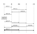
- FIG. 6 is a diagram showing a processing sequence for establishing a communication connection when the femtocell base station 51 is newly established.
- the femtocell base station 51 When the femtocell base station 51 is connected to the fixed communication network 3, the femtocell base station 51 establishes an S1 interface with the MME 8, and then sends a request signal M301 for requesting information about neighboring base stations. Are transmitted to the MME 8 via the fixed communication network 3 and the gateway 9.
- the S1 interface between the macrocell base stations 41 and 42 and the MME 7, the S1 interface between the femtocell base station 52 and the MME 8, and the S1 interface (or S10 interface) between the MME 7 and the MME 8 have already been established. Has been. Further, the MME 8 holds information related to the MME 7 located in the vicinity of itself.
- the MME 8 that has received the request signal M301 collects information related to neighboring base stations of the femtocell base station 51 based on the position information of the femtocell base station 51.
- the MME 8 specifies the femtocell base station 52 as a peripheral base station of the femtocell base station 51.
- the MME 8 transmits a request signal M302 for obtaining information related to the neighboring base stations of the femtocell base station 51 to the MME 7 together with the position information of the femtocell base station 51.
- the MME 7 that has received the request signal M ⁇ b> 302 collects information related to the neighboring base stations of the femtocell base station 51 based on the position information of the femtocell base station 51.
- the MME 7 specifies the macro cell base station 42 as the peripheral base station of the femto cell base station 51.
- MME7 returns the response signal M303 including the information regarding the macrocell base station 42 specified as a periphery base station to MME8.
- the MME 8 that has received the response signal M303 sends a response signal M304 including information on the macrocell base station 42 and the femtocell base station 52 specified as the neighboring base stations to the femtocell base station 51 via the gateway 9 and the fixed communication network 3. Send back.
- the femtocell base station 51 stores the information received from the MME 8, and then transmits a request signal M305 for requesting establishment of a communication connection to the femtocell base station 52 via the MME8. Is transmitted to the macrocell base station 42 via This request signal M305 includes setting information of the femtocell base station 51 such as a port number and position information used for the S1 interface.
- the macrocell base station 42 that has received the request signal M305 returns a response signal M306 to the request for establishment of the communication connection to the femtocell base station 51 via the MMEs 8 and 7.
- This response signal M306 includes setting information of the macrocell base station 42 such as a port number and position information used for the S1 interface.
- the femtocell base station 52 that has received the request signal M305 returns a response signal M306 to the request for establishment of a communication connection to the femtocell base station 51 via the MME8.
- the X2 over is performed between the femto cell base station 51, the macro cell base station 42, and the femto cell base station 52.
- a communication connection using the S1 interface is established.
- the femtocell base station 51, the macrocell base station 42, and the femtocell base station 52 communicate with each other their own setting information M307 such as a frequency band to be used. Further, when the mobile terminal 100 needs to move, information about the moving operation is communicated with each other via the communication connection.
- a predetermined logical interface is used between the femtocell base station 51 and the peripheral base stations (the macrocell base station 42 and the femtocell base station 52).
- a communication connection has been established. Therefore, since the femtocell base station 51 and the neighboring base stations can communicate information on the used frequency band with each other via the logical interface, by setting the used frequency band so that they do not overlap each other, Duplication of the used frequency band can be avoided. As a result, it is possible to suppress radio wave interference between adjacent cells.
- the femtocell base station 51 and the peripheral base station can be logically connected by tunneling the X2 interface to the S1 interface.
- the femtocell base station 51 and the peripheral base station can be logically connected without adding a new port for establishing the X2 interface separately from the S1 interface.
- the MME 8 can collect information on the neighboring base stations of the femtocell base station 51 from the MME 7. Since the MMEs 7 and 8 collect information on the peripheral base stations, it is not necessary to prepare the management server 10 (see FIG. 3) that holds the position information of the radio base stations, so that the configuration of the communication system 1 is simplified. It becomes possible.
- the setting information and the like of the femtocell base station 51 can be notified from the femtocell base station 51 to the neighboring base stations when a communication connection establishment request is made.
- the neighboring base station setting information and the like can be notified from the neighboring base station to the femtocell base station 51.
- FIG. 7 is a diagram showing a procedure of communication connection establishment processing using the X2 interface in the communication system 1 according to the fourth embodiment of the present invention.
- gateway (communication control device) 9 and femtocell base stations 51 and 52 are installed.
- the femtocell base station 53 is a newly installed femtocell base station.
- the femtocell base stations 51, 52 and 53 are connected to the mobile communication network 2 via the fixed communication network 3.
- the femtocell base stations 51, 52, and 53 can communicate with the mobile terminal by wireless communication, and can establish a communication connection using the X2 interface with other femtocell base stations.
- the gateway 9 can store various information of the femtocell base stations 51, 52, and 53, and can communicate with the femtocell base stations 51, 52, and 53. The gateway 9 also performs control for establishing a communication connection using the X2 interface between femtocell base stations.
- information for a mobile terminal to perform a moving operation between each femtocell base station is transmitted and received between each femtocell base station via the X2 interface.
- this information includes an ID for identifying a mobile terminal in the X2 interface, a UE Context, and the like.
- the UE Context is basic information of the mobile terminal such as UE ID, UE (mobile terminal) -base station state information indicating the idle state or connection state, and security information.
- the security information is security information between the mobile terminal and the base station and between the base station and the network, and is information such as an algorithm and a security key used for security.
- information indicating the interference received by each femtocell base station is transmitted and received between the femtocell base stations via the X2 interface.
- the interference information is interference information related to the time axis direction, specifically, in which time slot among a plurality of time slots in a radio frame transmitted from the femtocell base station to the mobile terminal. It is information which shows.
- the interference information transmitted / received using the X2 interface is interference information related to the frequency axis direction together with or separately from interference information related to the time axis direction. Specifically, this is information indicating which subcarrier is receiving interference among a plurality of subcarriers of a radio signal transmitted from the femtocell base station to the mobile terminal.
- load information of each femtocell base station is transmitted and received between the femtocell base stations via the X2 interface.
- a communication connection using the X2 interface is established between the femtocell base station 51 and the femtocell base station 52.
- data corresponding to the X2 interface is physically transmitted and received between femtocell base stations via, for example, the gateway 9 or other devices.
- the gateway 9 When the gateway 9 recognizes a femtocell base station (hereinafter also referred to as a target base station) that should newly establish a communication connection using an X2 interface with another femtocell base station, the gateway 9 communicates with the target base station.
- a connection establishment instruction indicating an instruction to perform connection establishment processing for establishing a communication connection using the X2 interface is notified to the other femtocell base station.
- the gateway 9 instructs all the femtocell base stations under its control to establish the X2 interface all at once.
- the gateway 9 notifies the connection establishment instruction to all the femtocell base stations under its control, that is, all femtocell base stations other than the target base station.
- the femtocell base station 53 transmits a base station registration request to the gateway 9.
- This base station registration request includes identification information unique to the femtocell base station, for example, Cell Global ID, in order for the gateway 9 to identify the femtocell base station.
- a USIM Universal Subscriber Identity Module
- IMSI International Mobile Subscriber Identity: subscriber identifier
- Step SQ3 when the gateway 9 receives the base station registration request from the femtocell base station 53 and recognizes that the femtocell base station 53 is newly installed, for example, all the femtocell base stations under its control, Then, the Femtocell base station 51 and the Femtocell base station 52 are simultaneously notified of a connection establishment instruction indicating an instruction to execute the X2 interface establishment procedure (Step SQ3).
- this X2 interface establishment procedure for example, the procedure as shown in FIG. 2 is performed so that an existing femtocell base station transmits a request signal or the like requesting establishment of a communication connection to a newly installed femtocell base station. Changed procedure.
- the femtocell base station 51 and the femtocell base station 52 receive a connection establishment instruction from the gateway 9 and establish a communication connection using the X2 interface with the newly installed femtocell base station 53. Therefore, an X2 interface establishment procedure is executed with the femtocell base station 53 (step SQ4).
- FIG. 8 is a diagram showing a procedure of communication connection disconnection processing using the X2 interface in the communication system 1 according to the fourth embodiment of the present invention.
- the femtocell base stations 51 and 52 are notified of connection establishment from the gateway 9 and perform connection establishment processing, and then establish a communication connection with the femtocell base station 53 using the X2 interface. It is determined whether or not the state should be maintained. If the femtocell base stations 51 and 52 determine that the communication connection establishment state should not be maintained, the femtocell base stations 51 and 52 disconnect the communication connection.
- the femtocell base station 51 and the femtocell base station 52 establish a communication connection using the X2 interface with the newly installed femtocell base station 53 (step SQ4)
- the femtocell base station It monitors whether or not the X2 interface with the station 53 is used, for example, whether or not predetermined data corresponding to the X2 interface is periodically transmitted and received between itself and the femtocell base station 53.
- step SQ5 when the femtocell base station 51 and the femtocell base station 52 detect that the X2 interface with the femtocell base station 53 is not used for a certain period of time (step SQ5), the femtocell base station 53 sets the X2 interface with the femtocell base station 53. The used communication connection is disconnected (step SQ6).
- the femtocell base station is instructed to execute the X2 interface establishment procedure by simultaneous notification. For this reason, it is conceivable that a communication connection using the X2 interface is established even between femtocell base stations that are not adjacent to each other.
- the communication system 1 after establishing the communication connection using the X2 interface, for example, when the femtocell base station detects that the X2 interface is not used for a certain period of time, the communication connection is disconnected. Thereby, waste of resources such as a processing amount such as a CPU (Central Processing Unit) and a memory amount in the femtocell base station can be suppressed.
- a processing amount such as a CPU (Central Processing Unit)
- a memory amount in the femtocell base station can be suppressed.
- the installation location of both is separated, or there is a shield between the two
- the mobile terminal does not move between the two.
- SON Self-Organizing Network
- a femtocell base station or a mobile terminal measures a radio signal transmitted from a neighboring femtocell base station, and various adjustments and Perform the setting process. For this reason, the function needs to be implemented in the femtocell base station.
- the gateway 9 is a femtocell base station that should newly establish a communication connection using another X2 interface with another femtocell base station.
- a plurality of femtocell bases other than the target base station are provided with a connection establishment instruction indicating an instruction to perform a connection establishment process for establishing a communication connection with the target base station using the X2 interface. Notify the station.
- the femtocell base station determines whether or not the communication connection establishment state using the X2 interface with the target base station should be maintained. If it is determined that it should not be maintained, the communication connection using the X2 interface is disconnected.
- the communication system according to the fourth embodiment of the present invention can be considered to be an approach different from the establishment process of the inter-base station interface using SON. That is, in the communication system according to the fourth embodiment of the present invention, assuming that there is a possibility of waste, a communication connection using the X2 interface is established with a newly installed target femtocell base station. After all femtocell base stations estimated to be established perform the X2 interface establishment procedure, unnecessary X2 interfaces are deleted.
- the gateway 9 notifies the connection establishment instruction to all femtocell base stations other than the target base station corresponding to the stored information.
- Such a configuration eliminates the need for selecting a femtocell base station that is a notification destination of a connection establishment instruction, and simplifies the process of notifying the connection establishment instruction.
- the femtocell base stations 51 and 52 receive a connection establishment instruction from the gateway 9 and perform a connection establishment process, and then perform communication with the target base station. If the X2 interface established in (1) is not used for a predetermined period, it is determined that the established state of the communication connection using the X2 interface with the target base station should not be maintained.
- information for the mobile terminal to perform a moving operation between the femtocell base stations, and information indicating the interference received by the femtocell base station And at least one of the load information of the femtocell base stations is transmitted and received between the femtocell base stations via a predetermined logical interface.
- the communication connection using the X2 interface is established between the femtocell base stations.
- the present invention is not limited to this.
- a configuration may be adopted in which a communication connection using the X2 interface is established between the femtocell base station and the macrocell base station, or between the macrocell base stations.
- the MMEs 7 and 8 shown in FIG. 1 notify the macro cell base station and the femtocell base station of connection establishment instructions as communication control apparatuses.
- connection establishment instructions and connection disconnection processing for the X2 interface with the femtocell base station that may move or turn off depending on the user's circumstances reduces labor and costs, and wastes various resources.
- the effect of suppressing the use can be obtained more remarkably.
- the gateway 9 is configured to notify the connection establishment instruction to a plurality of femtocell base stations other than the target base station. It is not a thing.
- the MME 7 or MME 8 shown in FIG. 1 may be configured to notify a connection establishment instruction as a communication control apparatus, or may be configured to notify a connection establishment instruction as a communication control apparatus from a macro cell base station or a femto cell base station. Good.
- the existing femtocell base station other than the newly installed femtocell base station is in a state where the X2 interface is established.
- the present invention is not limited to this.
- existing femtocell base stations there is a femtocell base station that has not established a communication connection using an X2 interface with another femtocell base station. It may be configured to instruct the establishment of the X2 interface.
- the femtocell base stations 51 and 52 are configured to disconnect the communication connection using the X2 interface with the femtocell base station 53 based on their own judgment.
- the present invention is not limited to this.
- the femtocell base stations 51 and 52 detect that the X2 interface with the femtocell base station 53 has not been used for a certain period of time and report to the gateway 9, and the gateway 9 and the femtocell base stations 51 and 52 and the femtocell It may be determined that the communication connection using the X2 interface with the base station 53 should not be maintained, and the femtocell base stations 51 and 52 are controlled to disconnect the communication connection.
- the gateway 9 recognizes the newly installed femtocell base station as the target base station, and between the target base station and another femtocell base station.
- the gateway 9 is intended for a femtocell base station that needs to establish a communication connection using an X2 interface with another femtocell base station for some reason, such as a femtocell base station that has been powered off for a long time. Any configuration may be used as long as it is recognized as a base station.
- the femtocell base station when the femtocell base station detects that the X2 interface with the target base station is not used for a certain period of time, the femtocell base station uses the X2 interface with the target base station.
- the present invention is not limited to this.
- the movement of the mobile terminal is performed only rarely between itself and the target base station, and the femtocell base station 53 uses the X2 interface between the self and the femtocell base station 53 during a predetermined period.
- the amount of data to be transmitted / received is equal to or smaller than a predetermined value, it may be determined that the established state of the communication connection using the X2 interface with the target base station should not be maintained and the communication connection is disconnected.
- the femtocell base station transmits a predetermined data to the target base station after establishing a communication connection using the X2 interface with the target base station, and the response time of the target base station for the predetermined data If it is equal to or greater than the predetermined value, it is determined that the communication connection establishment state should not be maintained. For example, after the femtocell base station establishes a communication connection using the X2 interface with the target base station, the femtocell base station transmits a packet to the target base station using a PING (Packet Internet Groper) command, and determines the response time from the target base station. taking measurement. Then, when the response time is equal to or greater than a predetermined value, the femtocell base station determines that the necessity for the communication connection is low and disconnects the communication connection.
- PING Packet Internet Groper
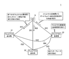
- FIG. 9 is a diagram showing a procedure of communication connection establishment processing using the X2 interface in the communication system 1 according to the fifth embodiment of the present invention.
- gateway communication control device 9
- femtocell base stations 51 and 52, MME 8, and HLR communication control device 10
- the gateway 9 performs control for establishing a communication connection using the X2 interface between femtocell base stations.
- a communication connection using the X2 interface is established between the femtocell base station 51 and the femtocell base station 52.
- the HLR 10 stores information such as position information indicating the installation location of each femtocell base station in the communication system 1 and manages each device in the communication system 1.
- the location information is, for example, the address that the user applied to the communication carrier as the installation location of the femtocell base station when the user contracts with the communication carrier.
- the gateway 9 instructs the femtocell base station adjacent to the newly installed femtocell base station to establish a communication connection using the X2 interface.
- the gateway 9 recognizes the femtocell base station 53 that is a target base station that should newly establish a communication connection using the X2 interface with another femtocell base station, all of the subordinate femtocell base stations That is, a connection establishment instruction is notified to the femtocell base stations arranged around the femtocell base station 53 among the femtocell base stations corresponding to the stored information.
- the gateway 9 establishes a connection from the femtocell base stations 51 and 52 based on information indicating the installation locations of the femtocell base stations 51 and 52 and the femtocell base station 53 that is the target base station. Select a femtocell base station to be notified of the instruction.
- step SQ11 when the femtocell base station 53 is newly installed (step SQ11), the femtocell base station 53 transmits a base station registration request to the HLR 10 via the gateway 9 and the MME 8 (step SQ12). .
- the HLR 10 receives the base station registration request from the femtocell base station 53 and sends a location registration response including the stored location information of the femtocell base stations 51 and 52 via the MME 8 and the gateway 9. It outputs to the base station 53 (step SQ13).
- the gateway 9 recognizes that the femtocell base station 53 is newly installed based on the location registration response received from the HLR 10, and the installation location of the femtocell base stations 51, 52, and 53, so that the femtocell A connection establishment instruction indicating an instruction to execute the X2 interface establishment procedure is notified to the femtocell base station 52 arranged around the base station 53 (step SQ14).
- the femtocell base station 52 receives a connection establishment instruction from the gateway 9, and establishes a communication connection using the X2 interface with the newly installed femtocell base station 53.
- An X2 interface establishment procedure is executed with the terminal 53 (step SQ15).
- the femtocell base station 52 establishes a communication connection using the X2 interface with the newly installed femtocell base station 53. Then (step SQ15), whether or not the X2 interface with the femtocell base station 53 is used, for example, predetermined data corresponding to the X2 interface is periodically transmitted and received between itself and the femtocell base station 53. Monitor whether or not.
- the femtocell base station 52 When the femtocell base station 52 detects that the X2 interface with the femtocell base station 53 is not used for a certain period of time, the femtocell base station 52 disconnects the communication connection with the femtocell base station 53 using the X2 interface.
- the gateway 9 recognizes a target base station that should newly establish a communication connection with another femtocell base station using the X2 interface.
- a connection establishment instruction indicating an instruction to perform the connection establishment process is notified.
- the configuration for notifying the connection establishment instruction only to the femtocell base stations arranged around the target base station enables the communication connection establishment process using the inter-base station interface to be performed more efficiently.
- the gateway 9 corresponds to each stored information based on the information indicating the installation location of each femtocell base station including the target base station.
- a femtocell base station to which a connection establishment instruction is to be notified is selected from the femtocell base stations.
- the configuration using the information indicating the installation location of the femtocell base station makes it possible to appropriately select the femtocell base station to which a connection establishment instruction should be notified.
- FIG. 10 is a diagram showing a procedure of communication connection establishment processing using the X2 interface in the communication system 1 according to the sixth embodiment of the present invention.
- gateway (relay device) 9 femtocell base stations 51, 52, 53, macrocell base station 41, and MMEs 7, 8 are installed.
- the installation location of the gateway 9 is the same as that of the communication system 1 shown in FIG. That is, the gateway 9 is connected between the mobile communication network 2 and the fixed communication network 3. Similarly to the communication system 1 shown in FIG. 1, the femtocell base stations 51, 52, and 53 are also connected to the mobile communication network 2 via the fixed communication network 3 and the gateway 9.
- a communication connection using the S1 interface is established between the macrocell base station 41 and the MME 7.
- a communication connection using the X2 interface is established between the macrocell base station 41 and the gateway 9.
- the gateway 9 looks like the MME 8 on the communication connection. That is, the femtocell base stations 51, 52, 53 communicate with the upper node side by regarding the gateway 9 as the MME8. Therefore, a communication connection using the S1 interface is established between the femtocell base stations 51, 52, and 53-gateway 9-MME8.
- the gateway 9 needs to convert between the X2 interface and the S1 interface.
- the effect of mounting the X2 interface between the macrocell base station 41 and the gateway 9 may be halved.
- the gateway 9 and the femtocell base stations 51, 52, 53 are a logical interface between the base station and the base station between the gateway 9 and the macrocell base station 41.
- a logical interface between the gateway 9 and the femtocell base stations 51, 52, 53 between the base station and the upper node for example, a base station-base station using the S1 interface A logical interface between them is used.
- the gateway 9 receives data corresponding to the X2 interface from the macrocell base station 41, and transmits the data to the femtocell base station 51, 52 or 53 using the S1 interface.
- the gateway 9 includes data corresponding to the X2 interface in a predetermined field of the frame defined by the S1 interface as one message, and transmits the message to the femtocell base station 51, 52, or 53.
- the gateway 9 transmits data corresponding to the X2 interface received from the femtocell base station 51, 52 or 53 to the macrocell base station 41 using the S1 interface. Specifically, the gateway 9 monitors the header of the frame defined by the S1 interface from the femtocell base station 51, 52 or 53, and indicates that the header indicates that the data includes data corresponding to the X2 interface. In this case, data corresponding to the X2 interface is extracted from the frame and transmitted to the macrocell base station 41.
- a communication connection using the X2over S1 interface is established between the gateway 9 and the femtocell base stations 51, 52 and 53, as if the macro cell base.
- a communication connection using the X2 interface can be established between the station 41 and the femtocell base stations 51, 52, and 53.
- the interface between the macro cell base station 41 and the gateway 9 is an X2 interface, whereas the gateway 9 and the femto cell base station.
- X2over S1 is used between 51, 52 and 53. This makes it possible to establish a pseudo-communication connection using the X2 interface between the macro cell base station 41, the gateway 9, and the femto cell base stations 51, 52, and 53.
Landscapes
- Engineering & Computer Science (AREA)
- Computer Networks & Wireless Communication (AREA)
- Signal Processing (AREA)
- Mobile Radio Communication Systems (AREA)
Abstract
Priority Applications (5)
| Application Number | Priority Date | Filing Date | Title |
|---|---|---|---|
| DE112010004294T DE112010004294T5 (de) | 2009-11-06 | 2010-10-29 | Kommunikationssystem; Kompaktbasisstation und Kommunikationsverfahren |
| US13/505,522 US8995984B2 (en) | 2009-11-06 | 2010-10-29 | Communication system, compact base station, and communication method |
| CN201080050106.2A CN102598848B (zh) | 2009-11-06 | 2010-10-29 | 通信系统、紧凑型基站和通信方法 |
| JP2011539358A JP5630440B2 (ja) | 2009-11-06 | 2010-10-29 | 通信システム、小型基地局、及び通信方法 |
| BR112012010711A BR102012010711A2 (fr) | 2009-11-06 | 2020-10-29 |
Applications Claiming Priority (2)
| Application Number | Priority Date | Filing Date | Title |
|---|---|---|---|
| JP2009-255326 | 2009-11-06 | ||
| JP2009255326 | 2009-11-06 |
Publications (1)
| Publication Number | Publication Date |
|---|---|
| WO2011055696A1 true WO2011055696A1 (fr) | 2011-05-12 |
Family
ID=43969936
Family Applications (1)
| Application Number | Title | Priority Date | Filing Date |
|---|---|---|---|
| PCT/JP2010/069339 WO2011055696A1 (fr) | 2009-11-06 | 2010-10-29 | Système de communication, micro station de base et procédé de communication |
Country Status (6)
| Country | Link |
|---|---|
| US (1) | US8995984B2 (fr) |
| JP (1) | JP5630440B2 (fr) |
| CN (1) | CN102598848B (fr) |
| BR (1) | BR102012010711A2 (fr) |
| DE (1) | DE112010004294T5 (fr) |
| WO (1) | WO2011055696A1 (fr) |
Cited By (5)
| Publication number | Priority date | Publication date | Assignee | Title |
|---|---|---|---|---|
| WO2012169113A1 (fr) * | 2011-06-10 | 2012-12-13 | パナソニック株式会社 | Dispositif de station de base et procédé de communication pour dispositif de station de base |
| WO2013031791A1 (fr) * | 2011-09-01 | 2013-03-07 | 日本電気株式会社 | Procédé de gestion, nœud de gestion, système de communication et support d'enregistrement de programme |
| WO2013141086A1 (fr) * | 2012-03-19 | 2013-09-26 | 京セラ株式会社 | Procédé de contrôle de communication, station de base, station de base domestique, et dispositif formant passerelle |
| WO2014167767A1 (fr) * | 2013-04-10 | 2014-10-16 | 日本電気株式会社 | Système de communication sans fil, station de base et procédé de communication sans fil |
| WO2018020818A1 (fr) * | 2016-07-27 | 2018-02-01 | ソニー株式会社 | Dispositif de commande de communication, dispositif de communication radio, procédé et programme |
Families Citing this family (13)
| Publication number | Priority date | Publication date | Assignee | Title |
|---|---|---|---|---|
| GB2454649B (en) * | 2007-10-26 | 2012-05-30 | Ubiquisys Ltd | Cellular basestation |
| EP2806706B1 (fr) * | 2011-12-14 | 2018-06-20 | Nec Corporation | Station de base radio, serveur, système de communication mobile et procédé de commande de fonctionnement |
| US9832717B2 (en) * | 2012-12-19 | 2017-11-28 | Blackberry Limited | Method and apparatus for layer 3 configuration in a heterogeneous network |
| JP5878134B2 (ja) * | 2013-01-09 | 2016-03-08 | 株式会社Nttドコモ | 上位基地局、下位基地局、および無線通信システム |
| CN104066199B (zh) * | 2013-03-19 | 2017-09-15 | 中国移动通信集团公司 | 通过小小区传输数据的方法及宏演进基站 |
| GB2512656A (en) * | 2013-04-05 | 2014-10-08 | Nec Corp | Communication system |
| EP2849356B1 (fr) * | 2013-09-12 | 2016-07-06 | Alcatel Lucent | Appareil, véhicule, procédé et programme informatique pour un émetteur-récepteur relais mobile et module de télématique pour véhicule |
| US20150350038A1 (en) * | 2014-05-27 | 2015-12-03 | Telefonaktiebolaget L M Ericsson (Publ) | Methods of generating community trust values for communities of nodes in a network and related systems |
| US9843408B2 (en) * | 2015-08-06 | 2017-12-12 | Verizon Patent And Licensing Inc. | Co-channel interference mitigation in wireless radio access network |
| US9967884B2 (en) | 2015-11-10 | 2018-05-08 | Netgear, Inc. | Dedicated backhaul for whole home coverage |
| US11184851B2 (en) | 2016-07-18 | 2021-11-23 | Netgear, Inc. | Power management techniques for a power sensitive wireless device |
| US10356681B2 (en) | 2016-09-21 | 2019-07-16 | Netgear, Inc. | Client roaming in a distributed multi-band wireless networking system |
| CN109474451A (zh) * | 2017-09-08 | 2019-03-15 | 中兴通讯股份有限公司 | 网络管理方法、装置、设备及计算机可读存储介质 |
Citations (4)
| Publication number | Priority date | Publication date | Assignee | Title |
|---|---|---|---|---|
| JP2008193526A (ja) * | 2007-02-06 | 2008-08-21 | Chugoku Electric Power Co Inc:The | 自律移動支援システム及びその制御方法 |
| JP2008278263A (ja) * | 2007-04-27 | 2008-11-13 | Ntt Docomo Inc | 移動通信システムにおける基地局装置及び方法 |
| JP2009044336A (ja) * | 2007-08-07 | 2009-02-26 | Fujitsu Ltd | 移動通信システム及びリンク確立方法 |
| JP2009200644A (ja) * | 2008-02-19 | 2009-09-03 | Panasonic Corp | 無線基地局の位置登録システム、無線基地局及びgps搭載セルラー端末並びに位置登録方法及び位置情報送信方法 |
Family Cites Families (12)
| Publication number | Priority date | Publication date | Assignee | Title |
|---|---|---|---|---|
| JP2004015103A (ja) | 2002-06-03 | 2004-01-15 | Nec Engineering Ltd | 高速大容量通信システム |
| JP4703577B2 (ja) * | 2007-01-17 | 2011-06-15 | 株式会社エヌ・ティ・ティ・ドコモ | 論理インタフェース設定方法、無線基地局、通信管理装置 |
| CN101365172B (zh) * | 2007-08-10 | 2014-08-13 | 中兴通讯股份有限公司 | 一种对家庭基站下用户的精确定位方法 |
| EP2183870B1 (fr) | 2007-08-13 | 2015-11-11 | QUALCOMM Incorporated | Optimisation de la livraison dans l'ordre de paquets de données pendant un transfert de communication sans fil |
| CN101816202B (zh) * | 2007-10-01 | 2015-01-07 | 日本电气株式会社 | 无线通信系统、无线通信方法、基站、移动站、基站控制方法、移动站控制方法及控制程序 |
| US8155647B2 (en) * | 2007-10-31 | 2012-04-10 | Telefonaktiebolaget L M Ericsson (Publ) | Method and apparatus for automatically determining neighbor cells in a wireless telecommunication system |
| US8379550B2 (en) * | 2008-01-31 | 2013-02-19 | Samsung Electronics Co., Ltd. | Location based femtocell device configuration and handoff |
| ATE545297T1 (de) | 2008-03-25 | 2012-02-15 | Ericsson Telefon Ab L M | Verfahren und kommunikationsnetzknoten in einem kommunikationsnetzsystem |
| US8260206B2 (en) * | 2008-04-16 | 2012-09-04 | Qualcomm Incorporated | Methods and apparatus for uplink and downlink inter-cell interference coordination |
| KR101400882B1 (ko) * | 2008-04-25 | 2014-06-30 | 삼성전자주식회사 | 펨토 기지국과 매크로 기지국간 무선 통신 방법 및 무선통신 시스템 |
| US8744493B2 (en) * | 2008-05-28 | 2014-06-03 | Via Telecom, Inc. | Localized silence area for mobile devices |
| GB2463001B (en) * | 2008-08-11 | 2012-07-04 | Picochip Designs Ltd | Communication network |
-
2010
- 2010-10-29 CN CN201080050106.2A patent/CN102598848B/zh not_active Expired - Fee Related
- 2010-10-29 WO PCT/JP2010/069339 patent/WO2011055696A1/fr active Application Filing
- 2010-10-29 US US13/505,522 patent/US8995984B2/en not_active Expired - Fee Related
- 2010-10-29 DE DE112010004294T patent/DE112010004294T5/de not_active Withdrawn
- 2010-10-29 JP JP2011539358A patent/JP5630440B2/ja not_active Expired - Fee Related
-
2020
- 2020-10-29 BR BR112012010711A patent/BR102012010711A2/pt not_active IP Right Cessation
Patent Citations (4)
| Publication number | Priority date | Publication date | Assignee | Title |
|---|---|---|---|---|
| JP2008193526A (ja) * | 2007-02-06 | 2008-08-21 | Chugoku Electric Power Co Inc:The | 自律移動支援システム及びその制御方法 |
| JP2008278263A (ja) * | 2007-04-27 | 2008-11-13 | Ntt Docomo Inc | 移動通信システムにおける基地局装置及び方法 |
| JP2009044336A (ja) * | 2007-08-07 | 2009-02-26 | Fujitsu Ltd | 移動通信システム及びリンク確立方法 |
| JP2009200644A (ja) * | 2008-02-19 | 2009-09-03 | Panasonic Corp | 無線基地局の位置登録システム、無線基地局及びgps搭載セルラー端末並びに位置登録方法及び位置情報送信方法 |
Non-Patent Citations (1)
| Title |
|---|
| MOTOROLA: "HeNB Interference Coordination", 3GPP TSG-RAN WG1 MEETING #59 R1-094839, 3GPP, - 8 November 2009 (2009-11-08) * |
Cited By (11)
| Publication number | Priority date | Publication date | Assignee | Title |
|---|---|---|---|---|
| WO2012169113A1 (fr) * | 2011-06-10 | 2012-12-13 | パナソニック株式会社 | Dispositif de station de base et procédé de communication pour dispositif de station de base |
| JP2012257178A (ja) * | 2011-06-10 | 2012-12-27 | Panasonic Corp | 基地局装置及び基地局装置の通信方法 |
| WO2013031791A1 (fr) * | 2011-09-01 | 2013-03-07 | 日本電気株式会社 | Procédé de gestion, nœud de gestion, système de communication et support d'enregistrement de programme |
| JPWO2013031791A1 (ja) * | 2011-09-01 | 2015-03-23 | 日本電気株式会社 | 管理方法、管理ノード、通信システム、およびプログラムの記録媒体 |
| US9439108B2 (en) | 2011-09-01 | 2016-09-06 | Nec Corporation | Management method, management node, communication system, and recording medium for program |
| WO2013141086A1 (fr) * | 2012-03-19 | 2013-09-26 | 京セラ株式会社 | Procédé de contrôle de communication, station de base, station de base domestique, et dispositif formant passerelle |
| JPWO2013141086A1 (ja) * | 2012-03-19 | 2015-08-03 | 京セラ株式会社 | 通信制御方法、基地局、ホーム基地局、及びゲートウェイ装置 |
| WO2014167767A1 (fr) * | 2013-04-10 | 2014-10-16 | 日本電気株式会社 | Système de communication sans fil, station de base et procédé de communication sans fil |
| JPWO2014167767A1 (ja) * | 2013-04-10 | 2017-02-16 | 日本電気株式会社 | 無線通信システム、基地局及び無線通信方法 |
| US10212701B2 (en) | 2013-04-10 | 2019-02-19 | Nec Corporation | Wireless communication system, base station and wireless communication method |
| WO2018020818A1 (fr) * | 2016-07-27 | 2018-02-01 | ソニー株式会社 | Dispositif de commande de communication, dispositif de communication radio, procédé et programme |
Also Published As
| Publication number | Publication date |
|---|---|
| DE112010004294T5 (de) | 2013-01-03 |
| CN102598848B (zh) | 2015-08-12 |
| US20120225646A1 (en) | 2012-09-06 |
| JPWO2011055696A1 (ja) | 2013-03-28 |
| JP5630440B2 (ja) | 2014-11-26 |
| US8995984B2 (en) | 2015-03-31 |
| CN102598848A (zh) | 2012-07-18 |
| BR102012010711A2 (fr) | 2019-09-24 |
Similar Documents
| Publication | Publication Date | Title |
|---|---|---|
| JP5630440B2 (ja) | 通信システム、小型基地局、及び通信方法 | |
| WO2019216717A1 (fr) | Procédé et appareil pour l'exécution d'une communication dans un système de communication sans fil | |
| CN102238667B (zh) | 一种建立基站间连接的方法 | |
| KR101561063B1 (ko) | 펨토 셀을 포함하는 무선 통신 네트워크에서의 lbo 서비스 지원 방법 및 장치 | |
| KR101647085B1 (ko) | 정보 전송 방법 및 장치 | |
| KR101764203B1 (ko) | 무선 통신 네트워크에서의 공통 상향 베어러 구성 방법 및 장치 | |
| WO2012141419A1 (fr) | Station de base femtocellulaire et système de gestion de station de base femtocellulaire | |
| CN111225427B (zh) | 一种通过网关建立x2的方法 | |
| EP3031228B1 (fr) | Procédés, systèmes et dispositifs de prise en charge de décrochage local dans une architecture de petite cellule | |
| US20150139056A1 (en) | Method and device for controlling and configuring state of function module of user equipment | |
| KR20100118532A (ko) | 무선 통신 네트워크에서 단말의 히스토리 정보 관리 방법 및 장치 | |
| JP5018999B2 (ja) | 移動体通信システム、無線通信方法、ゲートウェイ、HomeNodeB | |
| EP2384033B1 (fr) | Procédé pour obtenir l'adresse de transmission de la station de base cible et procédé pour établir la connexion d'interface x2 | |
| WO2014084475A1 (fr) | Procédé et appareil pour enregistrer un point d'accès par l'intermédiaire d'un réseau wifi par utilisation d'informations obtenues auprès d'un dispositif commun dans un système de convergence cellulaire-wifi | |
| KR20180132851A (ko) | 전용 코어 네트워크 천이를 처리하는 방법, 장비, 및 시스템 | |
| KR101651962B1 (ko) | 셀룰러 원격통신 네트워크에서 사용자 장비에 의한 강화된 액세스 선택을 위한 방법, 원격통신 네트워크, 및 사용자 장비의 강화된 액세스 선택을 위한 시스템 | |
| JP5417780B2 (ja) | 無線通信システム、端末装置及び無線基地局 | |
| JP6533591B2 (ja) | アクセスポイント間の自動切り替え方法、及び無線ルーティング装置 | |
| EP2359610B1 (fr) | Fourniture d'accès à un réseau gprs | |
| KR101612214B1 (ko) | 무선 통신 네트워크에서의 액세스를 위한 방법 및 장치 | |
| CN102186198A (zh) | 在无线系统中升级空中链路的设备和方法 | |
| EP2493242B1 (fr) | Dispositif de commande de communication mobile, système de communication mobile, et procédé de communication mobile | |
| CN114071715A (zh) | 用于寻呼的方法和设备 | |
| KR20130015963A (ko) | 지능적 서비스를 제공하는 통합 기지국 장치 및 그 방법 | |
| JP2014150492A (ja) | HetNetにおけるマクロセルとスモールセルとの間の通信路の設定方法およびその装置 |
Legal Events
| Date | Code | Title | Description |
|---|---|---|---|
| WWE | Wipo information: entry into national phase |
Ref document number: 201080050106.2 Country of ref document: CN |
|
| 121 | Ep: the epo has been informed by wipo that ep was designated in this application |
Ref document number: 10828256 Country of ref document: EP Kind code of ref document: A1 |
|
| WWE | Wipo information: entry into national phase |
Ref document number: 2011539358 Country of ref document: JP |
|
| WWE | Wipo information: entry into national phase |
Ref document number: 112010004294 Country of ref document: DE Ref document number: 1120100042942 Country of ref document: DE |
|
| WWE | Wipo information: entry into national phase |
Ref document number: 13505522 Country of ref document: US |
|
| WWE | Wipo information: entry into national phase |
Ref document number: 4832/CHENP/2012 Country of ref document: IN |
|
| REG | Reference to national code |
Ref country code: BR Ref legal event code: B01A Ref document number: 112012010711 Country of ref document: BR |
|
| 122 | Ep: pct application non-entry in european phase |
Ref document number: 10828256 Country of ref document: EP Kind code of ref document: A1 |
|
| ENP | Entry into the national phase |
Ref document number: 112012010711 Country of ref document: BR Kind code of ref document: A2 Effective date: 20120507 |