WO2011048827A1 - 内燃機関の制御装置 - Google Patents
内燃機関の制御装置 Download PDFInfo
- Publication number
- WO2011048827A1 WO2011048827A1 PCT/JP2010/054317 JP2010054317W WO2011048827A1 WO 2011048827 A1 WO2011048827 A1 WO 2011048827A1 JP 2010054317 W JP2010054317 W JP 2010054317W WO 2011048827 A1 WO2011048827 A1 WO 2011048827A1
- Authority
- WO
- WIPO (PCT)
- Prior art keywords
- pressure
- internal combustion
- combustion engine
- fuel
- control
- Prior art date
Links
Images


Classifications
-
- F—MECHANICAL ENGINEERING; LIGHTING; HEATING; WEAPONS; BLASTING
- F02—COMBUSTION ENGINES; HOT-GAS OR COMBUSTION-PRODUCT ENGINE PLANTS
- F02M—SUPPLYING COMBUSTION ENGINES IN GENERAL WITH COMBUSTIBLE MIXTURES OR CONSTITUENTS THEREOF
- F02M63/00—Other fuel-injection apparatus having pertinent characteristics not provided for in groups F02M39/00 - F02M57/00 or F02M67/00; Details, component parts, or accessories of fuel-injection apparatus, not provided for in, or of interest apart from, the apparatus of groups F02M39/00 - F02M61/00 or F02M67/00; Combination of fuel pump with other devices, e.g. lubricating oil pump
- F02M63/02—Fuel-injection apparatus having several injectors fed by a common pumping element, or having several pumping elements feeding a common injector; Fuel-injection apparatus having provisions for cutting-out pumps, pumping elements, or injectors; Fuel-injection apparatus having provisions for variably interconnecting pumping elements and injectors alternatively
- F02M63/0225—Fuel-injection apparatus having a common rail feeding several injectors ; Means for varying pressure in common rails; Pumps feeding common rails
- F02M63/023—Means for varying pressure in common rails
- F02M63/0235—Means for varying pressure in common rails by bleeding fuel pressure
- F02M63/025—Means for varying pressure in common rails by bleeding fuel pressure from the common rail
-
- F—MECHANICAL ENGINEERING; LIGHTING; HEATING; WEAPONS; BLASTING
- F02—COMBUSTION ENGINES; HOT-GAS OR COMBUSTION-PRODUCT ENGINE PLANTS
- F02D—CONTROLLING COMBUSTION ENGINES
- F02D41/00—Electrical control of supply of combustible mixture or its constituents
- F02D41/02—Circuit arrangements for generating control signals
- F02D41/04—Introducing corrections for particular operating conditions
- F02D41/06—Introducing corrections for particular operating conditions for engine starting or warming up
- F02D41/062—Introducing corrections for particular operating conditions for engine starting or warming up for starting
- F02D41/065—Introducing corrections for particular operating conditions for engine starting or warming up for starting at hot start or restart
-
- F—MECHANICAL ENGINEERING; LIGHTING; HEATING; WEAPONS; BLASTING
- F02—COMBUSTION ENGINES; HOT-GAS OR COMBUSTION-PRODUCT ENGINE PLANTS
- F02D—CONTROLLING COMBUSTION ENGINES
- F02D41/00—Electrical control of supply of combustible mixture or its constituents
- F02D41/30—Controlling fuel injection
- F02D41/38—Controlling fuel injection of the high pressure type
- F02D41/3809—Common rail control systems
- F02D41/3836—Controlling the fuel pressure
- F02D41/3845—Controlling the fuel pressure by controlling the flow into the common rail, e.g. the amount of fuel pumped
-
- F—MECHANICAL ENGINEERING; LIGHTING; HEATING; WEAPONS; BLASTING
- F02—COMBUSTION ENGINES; HOT-GAS OR COMBUSTION-PRODUCT ENGINE PLANTS
- F02D—CONTROLLING COMBUSTION ENGINES
- F02D41/00—Electrical control of supply of combustible mixture or its constituents
- F02D41/30—Controlling fuel injection
- F02D41/38—Controlling fuel injection of the high pressure type
- F02D41/3809—Common rail control systems
- F02D41/3836—Controlling the fuel pressure
- F02D41/3863—Controlling the fuel pressure by controlling the flow out of the common rail, e.g. using pressure relief valves
-
- F—MECHANICAL ENGINEERING; LIGHTING; HEATING; WEAPONS; BLASTING
- F02—COMBUSTION ENGINES; HOT-GAS OR COMBUSTION-PRODUCT ENGINE PLANTS
- F02M—SUPPLYING COMBUSTION ENGINES IN GENERAL WITH COMBUSTIBLE MIXTURES OR CONSTITUENTS THEREOF
- F02M37/00—Apparatus or systems for feeding liquid fuel from storage containers to carburettors or fuel-injection apparatus; Arrangements for purifying liquid fuel specially adapted for, or arranged on, internal-combustion engines
- F02M37/0047—Layout or arrangement of systems for feeding fuel
- F02M37/0052—Details on the fuel return circuit; Arrangement of pressure regulators
-
- F—MECHANICAL ENGINEERING; LIGHTING; HEATING; WEAPONS; BLASTING
- F02—COMBUSTION ENGINES; HOT-GAS OR COMBUSTION-PRODUCT ENGINE PLANTS
- F02M—SUPPLYING COMBUSTION ENGINES IN GENERAL WITH COMBUSTIBLE MIXTURES OR CONSTITUENTS THEREOF
- F02M63/00—Other fuel-injection apparatus having pertinent characteristics not provided for in groups F02M39/00 - F02M57/00 or F02M67/00; Details, component parts, or accessories of fuel-injection apparatus, not provided for in, or of interest apart from, the apparatus of groups F02M39/00 - F02M61/00 or F02M67/00; Combination of fuel pump with other devices, e.g. lubricating oil pump
- F02M63/02—Fuel-injection apparatus having several injectors fed by a common pumping element, or having several pumping elements feeding a common injector; Fuel-injection apparatus having provisions for cutting-out pumps, pumping elements, or injectors; Fuel-injection apparatus having provisions for variably interconnecting pumping elements and injectors alternatively
- F02M63/0225—Fuel-injection apparatus having a common rail feeding several injectors ; Means for varying pressure in common rails; Pumps feeding common rails
- F02M63/023—Means for varying pressure in common rails
- F02M63/0235—Means for varying pressure in common rails by bleeding fuel pressure
- F02M63/0245—Means for varying pressure in common rails by bleeding fuel pressure between the high pressure pump and the common rail
-
- F—MECHANICAL ENGINEERING; LIGHTING; HEATING; WEAPONS; BLASTING
- F02—COMBUSTION ENGINES; HOT-GAS OR COMBUSTION-PRODUCT ENGINE PLANTS
- F02D—CONTROLLING COMBUSTION ENGINES
- F02D2200/00—Input parameters for engine control
- F02D2200/02—Input parameters for engine control the parameters being related to the engine
- F02D2200/06—Fuel or fuel supply system parameters
- F02D2200/0602—Fuel pressure
-
- F—MECHANICAL ENGINEERING; LIGHTING; HEATING; WEAPONS; BLASTING
- F02—COMBUSTION ENGINES; HOT-GAS OR COMBUSTION-PRODUCT ENGINE PLANTS
- F02D—CONTROLLING COMBUSTION ENGINES
- F02D41/00—Electrical control of supply of combustible mixture or its constituents
- F02D41/02—Circuit arrangements for generating control signals
- F02D41/04—Introducing corrections for particular operating conditions
- F02D41/042—Introducing corrections for particular operating conditions for stopping the engine
-
- F—MECHANICAL ENGINEERING; LIGHTING; HEATING; WEAPONS; BLASTING
- F02—COMBUSTION ENGINES; HOT-GAS OR COMBUSTION-PRODUCT ENGINE PLANTS
- F02M—SUPPLYING COMBUSTION ENGINES IN GENERAL WITH COMBUSTIBLE MIXTURES OR CONSTITUENTS THEREOF
- F02M2200/00—Details of fuel-injection apparatus, not otherwise provided for
- F02M2200/60—Fuel-injection apparatus having means for facilitating the starting of engines, e.g. with valves or fuel passages for keeping residual pressure in common rails
-
- F—MECHANICAL ENGINEERING; LIGHTING; HEATING; WEAPONS; BLASTING
- F02—COMBUSTION ENGINES; HOT-GAS OR COMBUSTION-PRODUCT ENGINE PLANTS
- F02N—STARTING OF COMBUSTION ENGINES; STARTING AIDS FOR SUCH ENGINES, NOT OTHERWISE PROVIDED FOR
- F02N11/00—Starting of engines by means of electric motors
- F02N11/08—Circuits or control means specially adapted for starting of engines
- F02N11/0814—Circuits or control means specially adapted for starting of engines comprising means for controlling automatic idle-start-stop
- F02N11/0818—Conditions for starting or stopping the engine or for deactivating the idle-start-stop mode
Definitions
- the present invention relates to a control device for an internal combustion engine for controlling the internal combustion engine using an accumulator fuel injection device.
- the present invention relates to a control device for an internal combustion engine capable of executing idling stop control.
- an accumulator fuel injection device (common rail system) provided with a common rail for accumulating high-pressure fuel supplied by a high-pressure pump is known. It is used.
- a plurality of fuel injection valves are connected to the common rail, and various fuels are controlled by controlling the valve opening timing and valve opening time of each fuel injection valve while high-pressure fuel is supplied to each fuel injection valve. Fuel is injected into the cylinder of the internal combustion engine in an injection pattern.
- the high pressure pump is usually configured to be driven by the power of the internal combustion engine.
- the camshaft of the high-pressure pump is connected to the drive shaft of the internal combustion engine via a gear, and the high-pressure pump also operates during operation of the internal combustion engine, while the high-pressure pump also stops when the internal combustion engine stops. .
- the pressure in the common rail greatly affects fuel injection characteristics or combustibility.
- rail pressure control method there is a control method in which the flow rate of high-pressure fuel discharged from the common rail is adjusted by a pressure control valve provided in the common rail.
- a control device for an internal combustion engine that can shorten the stop time during the idling stop control of the internal combustion engine and can reliably improve the restartability. More specifically, when the internal combustion engine is automatically stopped by idling stop control, the discharge flow rate of the high-pressure pump is increased and the load of the internal combustion engine is adjusted to stop the crank angle at a predetermined crank angle suitable for restarting.
- a control device for an internal combustion engine is disclosed in which fuel injection is started simultaneously with the starter operation at the time of restart (see Patent Document 1).
- the compression ratio in the engine is sufficient to improve the restartability from the automatic stop state of the engine, and the fuel injection by the pressure accumulation type fuel injection device is possible. Is a factor. Of these two factors, whether or not the compression ratio is sufficient is a problem on the engine side, and whether or not fuel injection is possible is a problem on the accumulator fuel injection apparatus side. Whether or not fuel injection is possible in the accumulator type fuel injection device depends on whether or not the rail pressure is secured to a pressure higher than the pressure at which fuel can be normally injected (hereinafter referred to as “injectable pressure”). Therefore, in order to improve the restartability of the internal combustion engine, control may be performed so that the rail pressure is maintained at a high level even during the automatic stop of the internal combustion engine by the idling stop control.
- the target value of the rail pressure when starting to maintain the rail pressure during automatic stop is set to a value higher than the injectable pressure.
- the driving torque generated when the high-pressure pump starts to move is remarkably increased, which greatly increases the driving system of the high-pressure pump. Will give a heavy load. Specifically, when the internal combustion engine is restarted, the number of revolutions is rapidly increasing, and when the rail pressure is higher in such a state, rail pressure control by the pressure control valve is started. Then, rail pressure overshoot or undershoot may occur, and the rail pressure may become uncontrollable.
- the rail pressure control is not normally performed until the rotational speed of the internal combustion engine reaches a predetermined rotational speed.
- the flow control valve for adjusting the amount of fuel supplied to is opened, and the pressure control valve provided on the common rail is closed.
- a fuel discharge valve that opens when the pressure in the pressurizing chamber exceeds the sum of the rail pressure and the set force of the valve spring is provided between the pressurizing chamber of the high-pressure pump and the common rail. Therefore, if the fuel is supplied to the pressurizing chamber of the high-pressure pump when the internal combustion engine is restarted and the high-pressure pump is driven in a state where the rail pressure is high, the pressure in the pressurizing chamber is maintained until the fuel discharge valve is opened. Is significantly higher. As a result, a large force for pushing up the plunger for pressurizing the fuel is required, and a great load is generated on the drive system of the high-pressure pump.
- an object of the present invention is to provide a control device for an internal combustion engine that can reduce a load applied to a drive system of a high-pressure pump when the internal combustion engine is restarted from an automatic stop state.
- an accumulator fuel injection apparatus comprising: a common rail connected to a fuel injection valve; a high-pressure pump that pumps fuel to the common rail; and a pressure control valve that adjusts the flow rate of fuel discharged from the common rail.
- the control device for controlling the internal combustion engine by means of the control device for the internal combustion engine capable of executing the idling stop control detects that a predetermined idling stop condition is satisfied and instructs the internal combustion engine to automatically stop.
- An idling stop condition establishment detection unit that outputs a restart condition establishment detection unit that detects that a predetermined restart condition is established during automatic stop of the internal combustion engine and outputs an instruction to restart the internal combustion engine; Rail pressure detector that detects the pressure in the common rail, and the pressure in the common rail when the restart condition is met And a pressure control valve control unit that opens the pressure control valve before restarting the internal combustion engine when the predetermined threshold value is exceeded.
- the threshold value is preferably a value based on an allowable load from the high pressure pump to the drive system of the high pressure pump.
- the restart condition establishment detection unit detects that the restart condition is about to be established before the restart condition is established, and the pressure control valve control unit It is preferable to open the pressure control valve when it is detected that the start condition is about to be established soon and the pressure in the common rail is equal to or higher than the threshold value.
- control device for an internal combustion engine of the present invention, it is preferable to include a rail pressure determination unit that restarts the internal combustion engine when the pressure in the common rail becomes less than a threshold value after the restart condition is satisfied.
- the control device for an internal combustion engine of the present invention when the rail pressure is maintained in an unnecessarily high state when the internal combustion engine is restarted from the automatic stop state by the idling stop control, before the internal combustion engine is restarted.
- the pressure control valve is opened, and the rail pressure is forcibly reduced. Therefore, since the internal combustion engine is not restarted while the rail pressure is higher than necessary, the pressure in the pressurizing chamber is prevented from significantly increasing, and the load on the drive system of the high pressure pump is reduced.
- 1 is an overall view showing a configuration example of an accumulator fuel injection device. It is a figure for demonstrating the structural example of a high pressure pump. It is a block diagram for demonstrating the structural example of the control apparatus concerning the 1st Embodiment of this invention. It is a time chart for demonstrating the control method performed by the control apparatus of 1st Embodiment. It is a control flow for demonstrating the control method performed by the control apparatus of 1st Embodiment. It is a time chart for demonstrating the control method performed by the control apparatus of 2nd Embodiment. It is a control flow for demonstrating the control method performed by the control apparatus of 2nd Embodiment.
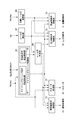
- FIG. 1 shows a configuration example of an accumulator fuel injection device 50 used for controlling an internal combustion engine.
- the accumulator fuel injection device 50 is a device for injecting fuel into a cylinder of a diesel engine 40 mounted on a vehicle, and includes a fuel tank 1, a low pressure pump 2, a flow control valve 8, and a high pressure pump. 5, a common rail 10, a pressure control valve 12, a fuel injection valve 13, a control device 60 and the like as main elements.
- the diesel engine 40 is provided with a rotational speed sensor 45 used for detecting the rotational speed of the engine and a starter 44 for forcibly rotating the drive shaft at the time of starting.
- the low pressure pump 2 and the pressurizing chamber 5a of the high pressure pump 5 are connected by low pressure fuel passages 18a and 18b.
- the pressurizing chamber 5a of the high pressure pump 5 and the common rail 10, and the common rail 10 and the fuel injection valve 13 are respectively high pressure fuel.
- the passages 37 and 39 are connected.
- return passages 30a to 30c for returning excess fuel not injected from the fuel injection valve 13 to the fuel tank 1 are connected to the high pressure pump 5, the common rail 10, the fuel injection valve 13, and the like.
- a flow control valve 8 is provided in the middle of the low-pressure fuel passage 18b in the high-pressure pump 5.
- the flow rate control valve 8 is, for example, an electromagnetic proportional flow rate control valve in which the stroke amount of the valve body is variable depending on the supply current value and the area of the fuel passage is adjustable, and the fuel sent to the pressurizing chamber 5a. It is used to adjust the flow rate.
- the flow rate control valve 8 used in the present embodiment is configured as a normally open flow rate control valve in which a fuel flow path is fully opened in a non-energized state. However, it may be a normally closed flow control valve in which the fuel flow path is fully closed in a non-energized state.
- the fuel passage branched from the low-pressure fuel passage 18b on the upstream side of the flow control valve 8 is provided with a pressure adjusting valve 14 arranged in parallel with the flow control valve 8.
- the pressure regulating valve 14 is connected to a return passage 30 a that communicates with the fuel tank 1.
- the pressure regulating valve 14 is an overflow valve that is opened when the differential pressure between the front and rear, that is, the pressure difference between the pressure in the low pressure fuel passage 18b and the pressure in the return passage 30a exceeds a predetermined value. ing. Therefore, in a state where the fuel is being pumped by the low-pressure pump 2, the pressure in the low-pressure fuel passages 18a and 18b is adjusted to be larger than the pressure in the return passage 30a by a predetermined differential pressure.
- the low-pressure pump 2 sucks up the fuel in the fuel tank 1 and pumps it, and supplies the fuel to the pressurizing chamber 5a of the high-pressure pump 5 through the low-pressure fuel passages 18a and 18b.
- a low-pressure pump 2 shown in FIG. 1 is an in-tank electric pump provided in a fuel tank 1 and is driven by a voltage supplied from a battery to pump fuel. However, the low pressure pump 2 may be provided outside the fuel tank 1, or may be a gear pump that is driven by the power of the diesel engine 40.
- the high-pressure pump 5 pressurizes fuel introduced into the pressurizing chamber 5 a by the low-pressure pump 2 through the fuel intake valve 6 by the plunger 7, and supplies high-pressure fuel to the common rail through the fuel discharge valve 9 and the high-pressure fuel passage 37. 10 to pump.
- the fuel discharge valve 9 has a check valve structure in which the sealing performance is improved as the rail pressure located on the discharge side is higher.
- the cam 15 that drives the high-pressure pump 5 is fixed to a cam shaft that is connected to the drive shaft of the diesel engine 40 via a gear.
- the high-pressure pump 5 shown in FIG. 1 includes two plungers 7. The two plungers 7 are pushed up by cams 15 and fuel is pressurized in the two pressurizing chambers 5a to the common rail 10. High pressure fuel is pumped.
- the high-pressure pump 5 of the pressure-accumulation fuel injection device 50 of this embodiment has a fuel-lubricated configuration that uses fuel for injection as lubricating oil, and the fuel that is sent into the high-pressure pump 5 via the low-pressure fuel passage 18a is Once it flows into the cam chamber 16, it is further sent to the pressurizing chamber 5a via the low pressure fuel passage 18b.
- the common rail 10 accumulates high-pressure fuel pumped from the high-pressure pump 5 and supplies high-pressure fuel to the plurality of fuel injection valves 13 connected via the high-pressure fuel passage 39.
- the common rail 10 is provided with a pressure control valve 12 and a pressure sensor 21.
- the pressure sensor 21 is a known pressure sensor such as a piezoelectric element sensor or a semiconductor sensor.
- the pressure control valve 12 is, for example, an electromagnetic proportional control valve in which the stroke amount of the valve body is variable depending on the supply current value and the area of the fuel passage is adjustable. The amount of power supplied to the pressure control valve 12 is controlled according to the target rail pressure and the required injection amount, and the rail pressure is adjusted by adjusting the flow rate of the high-pressure fuel discharged from the common rail 10 to the return passage 30b. .
- the pressure control valve 12 used in the present embodiment is configured as a normally open pressure control valve in which a fuel flow path is fully opened in a non-energized state. However, it may be a normally closed pressure control valve in which the fuel flow path is fully closed in a non-energized state.
- the fuel injection valve 13 connected to the common rail 10 includes a nozzle body provided with an injection hole and a nozzle needle that opens and closes the injection hole by advancing and retreating.
- the injection hole is closed by applying a back pressure to the rear end side of the nozzle needle, while the injection hole is opened by releasing the applied back pressure, and the high pressure supplied from the common rail 10.
- the fuel is injected into the cylinder of the diesel engine.
- the fuel injection valve 13 is capable of normal fuel injection when the rail pressure is equal to or higher than a predetermined injectable pressure.
- a piezo injector provided with a piezo element as back pressure control means or an electromagnetically controlled fuel injection valve provided with an electromagnetic solenoid as back pressure control means is used.
- a piezo injector is used, and this piezo injector employs a structure in which fuel does not easily leak into the return passage 30c other than a passage for releasing back pressure.
- FIG. 2 shows an example of a specific configuration of the high pressure pump 5.
- the high-pressure pump 5 includes a pump housing 51, a cylinder head 52 mounted in a cylindrical space 51a of the pump housing 51, a plunger 7 slidably held by a cylinder 52a of the cylinder head 52, and both ends of the cylinder head 52 and A spring 55, which is locked to the spring seat 59 and biases the plunger 7 downward, is interposed between the plunger 7 and the cam 15, and is used to push up the plunger 7 while centering as the cam 15 rotates.
- a tappet structure 58 is used to push up the plunger 7 while centering as the cam 15 rotates.
- the fuel intake valve 6 is disposed in the upper opening of the cylinder 52a of the cylinder head 52, and the fuel discharge valve 9 is disposed in the lateral direction with respect to the axial direction of the cylinder 52a via the fuel discharge passage 52b. ing.
- the flow control valve 8 and the pressure adjustment valve 14 provided in the high pressure pump 5 are not shown.
- a part of the cylinder 52a of the cylinder head 52 is closed by the inner peripheral surface of the cylinder head 52, the plunger 7, the fuel intake valve 6, and the fuel discharge valve 9, and is configured as a pressurizing chamber 5a. Yes.
- the fuel that has flowed into the pressurizing chamber 5a through the fuel intake valve 6 is pressurized in the pressurizing chamber 5a by the plunger 7 that is pushed up as the cam 15 rotates.
- the pressure in the pressurizing chamber 5a exceeds the sum of the set force of the valve spring of the fuel discharge valve 9 and the rail pressure, and the fuel discharge valve 9 is pushed open, so that pressurized fuel is pumped toward the common rail.
- FIG. 3 shows functional parts of the control device 60 of the diesel engine 40 according to the present embodiment that are related to the control performed when the diesel engine 40 is restarted from the automatic stop state by the idling stop control.
- a configuration example represented by blocks is shown.
- the control device 60 includes an idling stop control unit 63 including an idling stop condition establishment detection unit 61 and a restart condition establishment detection unit 62, a target rail pressure calculation unit 65, a rail pressure detection unit 67, and a rail pressure determination unit 69.
- the control device 60 is configured around a microcomputer having a known configuration, and each unit is realized by executing a program by the microcomputer. Further, the control device 60 includes a RAM (Random) (not shown) for storing calculation results and detection results at each unit.
- a storage means such as an access memory is provided.
- the idling stop control unit 63 issues an instruction to stop fuel injection and stop the diesel engine 40 when the idling stop condition establishment detection unit 61 detects the establishment of a predetermined idling stop condition. This is sent to the fuel injection valve control unit 71. At this time, the idling stop control unit 63 sends an instruction for shutting off the energization to the flow control valve 8 to the flow control valve control unit 73. In addition, the idling stop control unit 63 sends an instruction for energizing the pressure control valve 12 with a predetermined holding current A1 to the pressure control valve control unit 75 in order to maintain the rail pressure at a predetermined pressure.
- the idling stop control unit 63 resumes fuel injection when the restart condition establishment detection unit 62 detects that the predetermined restart condition is established while the diesel engine 40 is automatically stopped by the idling stop control. Then, an instruction for restarting the diesel engine 40 is sent to the fuel injection valve control unit 71 and the starter control unit 77. Further, the idling stop control unit 63 transmits the establishment of the restart condition to the rail pressure determination unit 69 when the restart condition is established.
- the idling stop condition detected by the idling stop condition establishment detection unit 61 is, for example, that the engine switch Sw is in an on state, the detection position Sg of the gear sensor indicates neutral, and the detection position Sb of the brake pedal sensor is At least one of the state in which the pedal is depressed, the rotational speed Ne of the diesel engine 40 is equal to or lower than a predetermined threshold, and the state where the vehicle speed V is 0 continues for a predetermined time or more.
- the condition can be that more than one condition is met, but is not limited to this.
- the restart condition detected by the restart condition establishment detection unit 62 is that the detection position Sg of the gear sensor is released from the neutral state during the automatic stop of the diesel engine 40, the accelerator pedal Acc is stepped on, etc.
- the present invention is not limited to this condition.
- the fuel injection valve control unit 71 calculates the target fuel injection amount Qtgt based on the engine speed Ne, the accelerator operation amount Acc, and the like, and the fuel injection valve 13 corresponding to the target fuel injection amount Qtgt. And a control signal is output to the fuel injection valve 13.
- the fuel injection valve control unit 71 stops fuel injection when a signal indicating that the idling stop condition is satisfied is transmitted from the idling stop control unit 63, and resumes fuel injection when a signal indicating that the restart condition is satisfied is transmitted. To do.
- the fuel injection valve control unit 71 of the control device 60 of the present embodiment instructs the start permission from the rail pressure determination unit 69 even when the establishment of the restart condition is transmitted after the automatic stop by the idling stop control. It is set so that the fuel injection control is not resumed until is received.
- the starter control unit 77 operates the starter 44 when the diesel engine 40 is started, and performs control for forcibly rotating the drive shaft to compress the inside of the cylinder.
- the starter control unit 77 of the control device 60 permits the start permission from the rail pressure determination unit 69 even when the establishment of the restart condition is transmitted after the diesel engine 40 is automatically stopped by the idling stop control.
- the starter 44 is set not to operate until the instruction is received.
- Target rail pressure calculation unit 65 calculates the target rail pressure Ptgt based on the engine speed Ne, the accelerator operation amount Acc, and the like, and stores it in the storage unit. Further, the rail pressure detection unit 67 continuously reads the sensor value of the pressure sensor 21 provided in the common rail 10, obtains the detected rail pressure Psensor, and stores it in the storage means.
- the rail pressure determination unit 69 continuously reads the detected rail pressure Psensor and the detected rail pressure Psensor is a predetermined value. It is determined whether or not the threshold is Prail_thr1 or more.
- the threshold value Prail_thr1 is set to a value that does not increase the load on the drive system of the high-pressure pump 5 even when driving of the high-pressure pump 5 is started.
- the threshold value Prail_thr1 is assumed to be larger than the injectable pressure at which normal injection from the fuel injection valve 13 is possible, and when the holding current A1 is energized to the pressure control valve 12 when the diesel engine 40 is automatically stopped by the idling stop control.
- the rail pressure determination unit 69 transmits an instruction signal for opening the pressure control valve 12 to the pressure control valve control unit 75.
- the rail pressure determination unit 69 is set to send a start permission instruction to the fuel injection valve control unit 71 and the starter control unit 77 when the detected rail pressure Psensor is less than the threshold value Prail_thr1.
- the flow rate control valve control unit 73 and the pressure control valve control unit 75 are basically configured so that the detected rail pressure Psensor becomes the target rail pressure Ptgt.
- the energization control of the control valve 8 or the pressure control valve 12 is executed.
- the flow rate control valve control unit 73 controls the flow rate of the fuel supplied to the pressurizing chamber 5a of the high pressure pump 5 by adjusting the opening degree of the flow rate control valve 8, and from the high pressure pump 5 to the common rail 10
- the rail pressure is adjusted by changing the flow rate of the high-pressure fuel pumped.
- the pressure control valve control unit 75 controls the flow rate of the return fuel discharged from the common rail 10 to the return passage 30b by adjusting the opening degree of the pressure control valve 12, thereby adjusting the rail pressure.
- the rail pressure is controlled by the flow rate control valve control unit 73, the pressure control valve control unit 75, or the combination of the two control units depends on the running state of the vehicle and the operating state of the diesel engine 40. It is divided according to. However, when the diesel engine 40 is started, the rail pressure is not controlled until the engine speed Ne detected by the speed sensor 45 reaches the predetermined speed Ne0, and basically the flow control valve 8 is not operated. Is held fully open and the pressure control valve 12 is closed.
- the flow control valve control unit 73 cuts off the power supply to the flow control valve 8. Since the flow control valve 8 of the present embodiment has a normally open configuration, the flow control valve 8 is fully opened when power is cut off when the diesel engine 40 is automatically stopped.
- the pressure control valve control unit 75 when the pressure control valve control unit 75 receives a control instruction accompanying the establishment of the idling stop condition from the idling stop control unit 63, the pressure control valve control unit 75 performs control to continuously energize the pressure control valve 12 with a predetermined holding current A1.
- This holding current A1 is a control value such that the rail pressure is adjusted to a value larger than the injectable pressure, and even when the diesel engine 40 automatically stops for a relatively long time, the rail pressure at the time of restarting is maintained. Is set to such a value that is ensured to be equal to or higher than the injectable pressure.
- the pressure control valve control unit 75 opens the pressure control valve 12 output from the rail pressure determination unit 69 because the rail pressure is equal to or higher than the threshold value Prail_thr1 when the restart condition of the diesel engine 40 is satisfied.
- control is performed to switch the current value to be supplied to the pressure control valve 12 from the holding current A1 to the valve opening current A2.
- the valve opening current A2 is set in advance to a current value such that the rail pressure is less than the threshold value Prail_thr1 and is equal to or greater than the injectable pressure.
- valve opening current A2 When the valve opening current A2 is applied to the pressure control valve 12 in a state where the rail pressure is equal to or higher than the threshold value Prail_thr1, the pressure control valve 12 is opened, and the rail pressure is reduced to be lower than the threshold value Prail_thr1. That is, when the diesel engine 40 is restarted, the pressure control valve 12 is basically closed. However, when the detected rail pressure Psensor when the restart condition is satisfied is equal to or higher than the threshold value Prail_thr1, the valve opening current is supplied to the pressure control valve 12. A2 is energized and the pressure control valve 12 is opened.
- valve opening current A2 is set to a current value such that the rail pressure is less than the threshold value Prail_thr1 and equal to or greater than the injectable pressure, so the rail pressure is reduced to less than the threshold value Prail_thr1.
- the restartability of the diesel engine 40 is not affected.
- the valve opening current A2 supplied to the pressure control valve 12 is not limited to a predetermined value in advance.
- the detected rail pressure Psensor immediately before the diesel engine 40 is automatically stopped by the idling stop control is the threshold value Prail_thr1. If it is less than the value, the current value supplied to the pressure control valve 12 at that time can be set as the valve opening current A2.
- the valve opening current A2 is set in this way, the rail pressure after the valve opening current A2 is supplied can be prevented from becoming less than the injectable pressure.
- step S11 after the start, it is determined whether or not a predetermined idling stop condition is satisfied (period t0 to t1 in FIG. 4).
- a predetermined idling stop condition is satisfied, the process proceeds to step S12, the fuel injection by the fuel injection valve 13 is stopped to stop the diesel engine 40, and the energization of the holding current A1 is started to the pressure control valve 12 in step S13 (FIG. 4 t1).
- step S14 it is determined whether or not a predetermined restart condition is satisfied. This step S14 is repeated until the restart condition is satisfied (period t1 to t2 in FIG. 4), and when the restart condition is satisfied, the process proceeds to step S15.
- step S15 the detected rail pressure Psensor is read, and it is determined whether or not the detected rail pressure Psensor is greater than or equal to a threshold value Prail_thr1 (t2 in FIG. 4). If the detected rail pressure Psensor is less than the threshold value Prail_thr1, the process proceeds to step S18, the starter 44 is operated as it is, and fuel injection from the fuel injection valve 13 is started to restart the diesel engine 40. On the other hand, if the detected rail pressure Psensor is greater than or equal to the threshold value Prail_thr1 in step S15, the process proceeds to step S16, and the current supplied to the pressure control valve 12 is switched from the holding current A1 to the valve opening current A2. As a result, the pressure control valve 12 is opened, and the rail pressure begins to decrease accordingly.
- a threshold value Prail_thr1 t2 in FIG. 4
- the detected rail pressure Psensor is continuously read, and it is determined whether or not the detected rail pressure Psensor is less than the threshold value Prail_thr1 in step S17 until the detected rail pressure Psensor becomes less than the threshold value Prail_thr1 (FIG. 4). T2 to t3). Then, when the detected rail pressure Psensor becomes less than the threshold value Prail_thr1, the process proceeds to step S18, where the starter 44 is operated and fuel injection from the fuel injection valve 13 is started to restart the diesel engine 40 (t3 in FIG. 4). ).
- step S19 After the diesel engine 40 is restarted, it is determined in step S19 whether or not the engine speed Ne has reached a predetermined speed Ne0 (period t3 to t4 in FIG. 4). When the rotational speed Ne0 is reached, the process proceeds to step S20 to shift to the rail pressure control mode (t4 in FIG. 4).
- the fuel injection valve is not provided with a fuel leak passage other than the fuel used for back pressure control, and the pressure accumulation type fuel is configured such that the rail pressure does not easily decrease when the diesel engine 40 is automatically stopped.
- the present invention is not limited to the case where such a pressure accumulation type fuel injection device 50 is used. Even when the fuel injection valve has a leak passage for fuel other than the fuel used for back pressure control, and the pressure accumulation type fuel injection device is configured such that the rail pressure decreases when the diesel engine is automatically stopped, the diesel engine 40 When the rail pressure is relatively high when the restart condition is satisfied, the pressure control valve 12 is opened to reduce the load on the drive system of the high-pressure pump.
- the control apparatus for an internal combustion engine according to the second embodiment of the present invention is configured to perform control for opening the pressure control valve before the restart condition of the internal combustion engine is satisfied.
- the control device for an internal combustion engine and the control method for the internal combustion engine of the present embodiment will be described focusing on differences from the control device for the internal combustion engine and the control method for the internal combustion engine according to the first embodiment.
- Control Device for the diesel engine 40 according to the present embodiment is basically configured in the same manner as the control device 60 for the internal combustion engine according to the first embodiment, but will be restarted soon after the automatic stop by the idling stop control.
- a function for determining that the condition is satisfied and opening the pressure control valve in advance is added to the restart condition satisfaction detection unit and the rail pressure determination unit.
- the restart condition establishment detection unit basically has the same function as the restart condition establishment detection unit in the control device of the first embodiment. It is determined that when a part of the start condition is satisfied, the restart condition is determined to be satisfied soon, and a restart condition satisfaction preliminary signal is transmitted to the rail pressure determination unit.
- the release of the detection position of the gear sensor from the neutral state is before the accelerator pedal is depressed. Often done in stages.
- the restart condition establishment detection unit sends a restart condition establishment preliminary signal to the rail pressure determination unit when detecting information that can be determined that such a restart condition will soon be established. Information for determining that the restart condition will soon be satisfied is not limited to the above-described example.
- the rail pressure determination unit receives the restart condition establishment preliminary signal from the restart condition establishment detection unit, it determines whether or not the detected rail pressure Psensor is equal to or greater than a predetermined threshold value Prail_thr1, and the detected rail pressure Psensor is If it is equal to or greater than the threshold value Prail_thr1, an instruction to open the pressure control valve 12 is sent to the pressure control valve control unit 75. As a result, the pressure control valve 12 is opened before the restart condition is satisfied, and the rail pressure starts to decrease accordingly.
- the rail pressure becomes less than the threshold value Prail_thr1, or when the restart condition is satisfied, even if the rail pressure is equal to or higher than the threshold value Prail_thr1, the time until the rail pressure becomes the threshold value Prail_thr1 is shortened thereafter. Therefore, the time before restart is shortened.
- step S51 after the start, it is determined whether or not a predetermined idling stop condition is satisfied (period t0 to t1 in FIG. 6).
- a predetermined idling stop condition is satisfied, the process proceeds to step S52, the fuel injection by the fuel injection valve 13 is stopped and the diesel engine 40 is stopped.
- step S53 the holding of the holding current A1 is started to the pressure control valve 12 (FIG. 6 t1).
- step S54 it is determined whether or not the diesel engine 40 will be restarted soon. This step S54 is repeated until a restart condition satisfaction preliminary signal is detected (period t1 to t2 in FIG. 6), and when it is determined that the diesel engine 40 will be restarted soon, the routine proceeds to step S55.
- step S55 the detected rail pressure Psensor is read, and it is determined whether or not the detected rail pressure Psensor is greater than or equal to a threshold value Prail_thr1 (t2 in FIG. 6). If the detected rail pressure Psensor is less than the threshold value Prail_thr1, the process proceeds directly to step S57. On the other hand, if the detected rail pressure Psensor is greater than or equal to the threshold value Prail_thr1, the process proceeds to step S56, the energization current to the pressure control valve 12 is switched from the holding current A1 to the valve opening current A2, and then the process proceeds to step S57. When the valve opening current A2 is supplied to the pressure control valve 12, the pressure control valve 12 is opened, and the rail pressure begins to decrease accordingly.
- a threshold value Prail_thr1 t2 in FIG. 6
- step S57 the determination as to whether or not the restart condition is satisfied is repeated until the restart condition is satisfied (period t2 to t3 in FIG. 6).
- the process proceeds to step S58 to detect the detection rail. It is determined whether or not the pressure Psensor is less than the threshold value Prail_thr1 (t3 in FIG. 6).
- the process proceeds to step S59, where the starter 44 is operated and fuel injection from the fuel injection valve 13 is started to restart the diesel engine 40 (t4 in FIG. 6).
- this step S58 is repeated until the detected rail pressure Psensor becomes less than the threshold value Prail_thr1 (period t3 to t4 in FIG. 6).
- step S60 After the diesel engine 40 is restarted, it is determined in step S60 whether or not the engine speed Ne has reached a predetermined speed Ne0 (period t4 to t5 in FIG. 6). When the rotational speed Ne0 is reached, the process proceeds to step S61 to shift to the rail pressure control mode (time t5 in FIG. 6).
- the rail pressure can be reduced until the restart condition is satisfied. Therefore, the time from when the restart condition is satisfied until the restart is permitted is shortened, and the restartability of the diesel engine 40 is improved. Further, when the fuel injection from the fuel injection valve 13 is started and the driving of the high pressure pump 5 is started, the rail pressure is in a lowered state, so that the pressure in the pressurizing chamber 5a is not significantly increased. , No large force is required to raise the plunger 7. Therefore, it is possible to avoid applying a great load to the drive system of the high-pressure pump 5 while the oil film at the contact portion between the cam 15 and the roller 54 of the tappet structure 58 is insufficient.
Abstract
内燃機関の自動停止状態からの再始動時に高圧ポンプの駆動系に与えられる負荷を低減することができる内燃機関の制御装置を提供する。 アイドリングストップ制御を実行可能な内燃機関の制御装置において、所定のアイドリングストップ条件が成立したことを検出するとともに内燃機関を自動停止させるよう指示を出力するアイドリングストップ条件成立検出部と、内燃機関の自動停止中に所定の再始動条件が成立したことを検出するとともに内燃機関を再始動させるよう指示を出力する再始動条件成立検出部と、コモンレール内の圧力を検出するレール圧検出部と、再始動条件の成立時にコモンレール内の圧力が所定の閾値以上となるときには、内燃機関を再始動させる前に圧力制御弁を開弁する圧力制御弁制御部と、を備える。
Description
本発明は、蓄圧式燃料噴射装置を用いて内燃機関の制御を行うための内燃機関の制御装置に関するものである。特に、アイドリングストップ制御を実行可能な内燃機関の制御装置に関するものである。
従来、ディーゼルエンジンをはじめとする内燃機関の気筒内に燃料を噴射する装置として、高圧ポンプによって供給される高圧状態の燃料を蓄積するためのコモンレールを備えた蓄圧式燃料噴射装置(コモンレールシステム)が用いられている。コモンレールには複数の燃料噴射弁が接続されており、高圧の燃料が各燃料噴射弁に供給された状態で各燃料噴射弁の開弁時期及び開弁時間が制御されることで、様々な燃料噴射パターンで内燃機関の気筒内に燃料が噴射される。
この蓄圧式燃料噴射装置において、通常、高圧ポンプは内燃機関の動力によって駆動されるように構成されている。具体的には、高圧ポンプのカムシャフトはギアを介して内燃機関のドライブシャフトに連結されており、内燃機関の運転中には高圧ポンプも作動する一方、内燃機関の停止時には高圧ポンプも停止する。
蓄圧式燃料噴射装置では、コモンレール内の圧力(以下「レール圧」と称する。)が燃料噴射特性あるいは燃焼性に大きく影響する。レール圧の制御方法として、コモンレールに設けられた圧力制御弁によって、コモンレールから排出される高圧燃料の流量を調節する制御方法がある。
このような蓄圧式燃料噴射装置を用いた内燃機関の制御において、近年、燃費の向上や、排気ガス量及び騒音の低減等を目的として、内燃機関が搭載された車両の一時停止中に内燃機関を自動停止させるアイドリングストップ制御が実用化されている。このアイドリングストップ制御においては、所定のアイドリングストップ条件が成立したときに内燃機関が自動停止させられるとともに、自動停止中に所定の再始動条件が成立したときに内燃機関が再始動させられる。このアイドリングストップ制御が実行可能な内燃機関が搭載された車両においては、自動停止状態からの再始動性が商品性に重要な影響を与える要素となっている。
そこで、内燃機関のアイドリングストップ制御中の停止時間を短縮したり、再始動性を確実に向上させたりすることのできる内燃機関の制御装置が提案されている。より具体的には、アイドリングストップ制御による内燃機関の自動停止時に高圧ポンプの吐出流量を増加させ、内燃機関の負荷を調節することで、クランク角を再始動に適した所定のクランク角で停止させ、再始動時にはスタータの作動と同時に燃料噴射を開始させるようにした内燃機関の制御装置が開示されている(特許文献1参照)。
内燃機関が、例えばディーゼルエンジンの場合、エンジンの自動停止状態からの再始動性を向上させるためには、エンジンにおける圧縮比が十分であり、かつ、蓄圧式燃料噴射装置による燃料噴射が可能であることが要因となる。これらの二つの要因のうち、圧縮比が十分であるか否かはエンジン側の問題であり、燃料噴射が可能であるか否かは蓄圧式燃料噴射装置側の問題である。蓄圧式燃料噴射装置において燃料噴射が可能であるか否かは、レール圧が燃料の正常噴射が可能な圧力(以下「噴射可能圧力」と称する。)以上に確保されているか否かによる。そのため、内燃機関の再始動性を向上させるために、アイドリングストップ制御による内燃機関の自動停止中においても、レール圧が高い状態で維持されるように制御が行われることがある。
このとき、コモンレールに接続された燃料噴射弁や高圧ポンプ、圧力制御弁等が閉じられている場合であっても、これらを含む燃料高圧系に存在する微細な隙間から高圧の燃料の一部が燃料低圧系にリークしてレール圧が徐々に低下する場合がある。そのため、自動停止時にレール圧を維持し始めるときのレール圧の目標値は、噴射可能圧力よりも高い値に設定される。
ここで、内燃機関の再始動時に、レール圧が高い状態で維持されたまま内燃機関を始動させようとすると、高圧ポンプの動き出し時に発生する駆動トルクが著しく大きくなり、高圧ポンプの駆動系に多大な負荷を与えることになる。具体的には、内燃機関の再始動時は回転数が急激に上昇する状態にあり、このような状態でさらにレール圧が高い状態となっているときに圧力制御弁によるレール圧制御を開始したとすると、レール圧のオーバーシュートあるいはアンダーシュートが発生して、レール圧が制御不能に陥るおそれがある。そのため、内燃機関の再始動時においては、レール圧制御を速やかに実行可能にするために、通常、内燃機関の回転数が所定の回転数に到達するまではレール圧制御は行わずに、コモンレールへの燃料の供給量を調節する流量制御弁は開かれ、コモンレールに備えられた圧力制御弁は閉じられる。
このとき、高圧ポンプの加圧室とコモンレールとの間には、加圧室内の圧力がレール圧とバルブスプリングのセット力との和を上回ったときに開弁する燃料吐出弁が備えられているため、内燃機関の再始動時に高圧ポンプの加圧室に燃料が供給され、かつ、レール圧が高い状態で高圧ポンプを駆動させると、燃料吐出弁が開かれるまでの期間は加圧室内の圧力が著しく高くなる。その結果、燃料を加圧するためのプランジャを押し上げる大きな力が必要になって、高圧ポンプの駆動系に多大な負荷が発生する。
また、高圧ポンプの停止状態では、カムシャフトに固定されたカムと、カムの回転力をプランジャの上昇力として伝達するタペットとの接触部位において、潤滑油あるいは潤滑用燃料が流れ出し、油膜が不十分な状態となっている。このようにタペットとカムとの接触部位の油膜が不十分な状態となっている高圧ポンプの動き出し時に高圧ポンプの駆動系に多大な負荷が与えられると、高圧ポンプの耐久性を低下させることにつながる。
そこで、本発明の発明者は鋭意努力し、アイドリングストップ制御による内燃機関の自動停止状態から内燃機関を再始動させる際にレール圧が必要以上に高くなっている場合には、内燃機関の再始動前にコモンレールに設けられた圧力制御弁を開弁することにより上述した問題を解決できることを見出し、本発明を完成させたものである。すなわち、本発明は、内燃機関の自動停止状態からの再始動時に高圧ポンプの駆動系に与えられる負荷を低減することができる内燃機関の制御装置を提供することを目的とする。
本発明によれば、燃料噴射弁が接続されたコモンレールと、コモンレールに燃料を圧送する高圧ポンプと、コモンレールから排出される燃料の流量を調節する圧力制御弁と、を備えた蓄圧式燃料噴射装置によって内燃機関の制御を行うための制御装置であって、アイドリングストップ制御を実行可能な内燃機関の制御装置において、所定のアイドリングストップ条件が成立したことを検出するとともに内燃機関を自動停止させるよう指示を出力するアイドリングストップ条件成立検出部と、内燃機関の自動停止中に所定の再始動条件が成立したことを検出するとともに内燃機関を再始動させるよう指示を出力する再始動条件成立検出部と、コモンレール内の圧力を検出するレール圧検出部と、再始動条件の成立時にコモンレール内の圧力が所定の閾値以上となるときには、内燃機関を再始動させる前に圧力制御弁を開弁する圧力制御弁制御部と、を備えることを特徴とする内燃機関の制御装置が提供され、上述した問題を解決することができる。
また、本発明の内燃機関の制御装置を構成するにあたり、閾値が、高圧ポンプから高圧ポンプの駆動系への許容される負荷に基づく値であることが好ましい。
また、本発明の内燃機関の制御装置を構成するにあたり、再始動条件成立検出部は、再始動条件の成立前に再始動条件が間もなく成立することを検出し、圧力制御弁制御部は、再始動条件が間もなく成立することが検出されたときであってコモンレール内の圧力が閾値以上となっているときに圧力制御弁を開弁することが好ましい。
また、本発明の内燃機関の制御装置を構成するにあたり、再始動条件の成立後にコモンレール内の圧力が閾値未満となったときに内燃機関を再始動させるレール圧判定部を備えることが好ましい。
本発明の内燃機関の制御装置によれば、アイドリングストップ制御による内燃機関の自動停止状態からの再始動時にレール圧が必要以上に高い状態で維持されている場合には、内燃機関の再始動前に圧力制御弁が開弁され、レール圧が強制的に低下させられる。したがって、レール圧が必要以上に高い状態のまま内燃機関が再始動させられることがなくなるために、加圧室内の圧力が著しく上昇することが抑えられ、高圧ポンプの駆動系への負荷が低減される。また、内燃機関の始動後にレール圧が上昇し加圧室内の圧力が高められるときには、高圧ポンプの駆動によってタペットとカムとの接触部位に潤滑油又は潤滑用燃料が浸透して油膜が形成されるために、高圧ポンプの耐久性の低下が抑えられる。
以下、図面を参照しながら、本発明にかかる内燃機関の制御装置に関する実施の形態について具体的に説明する。ただし、かかる実施の形態は、本発明の一態様を示すものであって本発明を限定するものではなく、本発明の範囲内で任意に態様を変更することが可能である。なお、それぞれの図中、同じ符号を付してあるものは同じ部材を示しており、適宜説明が省略されている。
1.蓄圧式燃料噴射装置
図1は、内燃機関の制御に用いられる蓄圧式燃料噴射装置50の構成例を示している。この蓄圧式燃料噴射装置50は、車両に搭載されたディーゼルエンジン40の気筒内に燃料を噴射するための装置であって、燃料タンク1と、低圧ポンプ2と、流量制御弁8と、高圧ポンプ5と、コモンレール10と、圧力制御弁12と、燃料噴射弁13と、制御装置60等を主たる要素として備えている。
図1は、内燃機関の制御に用いられる蓄圧式燃料噴射装置50の構成例を示している。この蓄圧式燃料噴射装置50は、車両に搭載されたディーゼルエンジン40の気筒内に燃料を噴射するための装置であって、燃料タンク1と、低圧ポンプ2と、流量制御弁8と、高圧ポンプ5と、コモンレール10と、圧力制御弁12と、燃料噴射弁13と、制御装置60等を主たる要素として備えている。
ディーゼルエンジン40には、エンジン回転数の検出に用いられる回転数センサ45と、始動時にドライブシャフトを強制的に回転させるためのスタータ44とが備えられている。
低圧ポンプ2と高圧ポンプ5の加圧室5aとは低圧燃料通路18a、18bで接続されており、高圧ポンプ5の加圧室5aとコモンレール10、及びコモンレール10と燃料噴射弁13はそれぞれ高圧燃料通路37、39で接続されている。また、高圧ポンプ5やコモンレール10、燃料噴射弁13等には、燃料噴射弁13から噴射されない余剰の燃料を燃料タンク1に戻すためのリターン通路30a~30cが接続されている。
高圧ポンプ5内の低圧燃料通路18bの途中には流量制御弁8が備えられている。流量制御弁8は、例えば、供給電流値によって弁体のストローク量が可変とされ、燃料通過路の面積が調節可能な電磁比例式の流量制御弁が用いられ、加圧室5aに送られる燃料の流量を調節するために用いられる。本実施形態で用いられる流量制御弁8は、非通電状態で燃料の流路が全開となるノーマルオープンの流量制御弁として構成されている。ただし、非通電状態で燃料の流路が全閉となるノーマルクローズの流量制御弁であってもよい。
流量制御弁8よりも上流側の低圧燃料通路18bから分岐する燃料通路には、流量制御弁8と並列に配置された圧力調整弁14が備えられている。この圧力調整弁14は、燃料タンク1に通じるリターン通路30aに接続されている。この圧力調整弁14は、前後の差圧、すなわち、低圧燃料通路18b内の圧力と、リターン通路30a内の圧力との差圧が所定値を越えたときに開弁されるオーバーフローバルブが用いられている。そのため、低圧ポンプ2によって燃料が圧送されている状態においては、低圧燃料通路18a、18b内の圧力が、リターン通路30a内の圧力に対して所定の差圧分大きくなるように調整される。
低圧ポンプ2は、燃料タンク1内の燃料を吸い上げて圧送し、低圧燃料通路18a、18bを介して高圧ポンプ5の加圧室5aに燃料を供給する。図1に示す低圧ポンプ2は燃料タンク1内に備えられたインタンクの電動ポンプであって、バッテリーから供給される電圧によって駆動されて燃料を圧送する。ただし、低圧ポンプ2は、燃料タンク1の外部に設けられるものであってもよく、また、ディーゼルエンジン40の動力によって駆動するギアポンプであってもよい。
高圧ポンプ5は、燃料吸入弁6を介して低圧ポンプ2によって加圧室5aへ導入される燃料をプランジャ7によって加圧し、高圧状態の燃料を燃料吐出弁9及び高圧燃料通路37を介してコモンレール10に圧送する。燃料吐出弁9は、吐出側に位置するレール圧が高いほどシール性が高められる逆止弁構造となっている。
高圧ポンプ5を駆動するカム15は、ディーゼルエンジン40のドライブシャフトにギアを介して連結されたカムシャフトに固定されている。図1に示す高圧ポンプ5は二本のプランジャ7を備えており、この二本のプランジャ7がカム15によって押し上げられ、二つの加圧室5a内で燃料が加圧されてコモンレール10に対して高圧の燃料が圧送される。
本実施形態の蓄圧式燃料噴射装置50の高圧ポンプ5は、噴射用燃料を潤滑油として用いる燃料潤滑式の構成となっており、低圧燃料通路18aを介して高圧ポンプ5内に送られる燃料は一旦カム室16内に流れ込み、そこからさらに低圧燃料通路18bを介して加圧室5aに送られる。
コモンレール10は、高圧ポンプ5から圧送される高圧の燃料を蓄積し、高圧燃料通路39を介して接続された複数の燃料噴射弁13に対して高圧の燃料を供給する。このコモンレール10には、圧力制御弁12及び圧力センサ21が設けられている。このうち圧力センサ21は、圧電素子センサや半導体センサなど公知の圧力センサが用いられる。
また、圧力制御弁12は、例えば、供給電流値によって弁体のストローク量が可変とされ、燃料通過路の面積が調節可能な電磁比例式の制御弁が用いられる。目標レール圧や要求噴射量に応じて圧力制御弁12への通電量が制御され、コモンレール10からリターン通路30bに排出される高圧の燃料の流量が調節されることで、レール圧が調節される。本実施形態で用いられる圧力制御弁12は、非通電状態で燃料の流路が全開となるノーマルオープン型の圧力制御弁として構成されている。ただし、非通電状態で燃料の流路が全閉となるノーマルクローズ型の圧力制御弁であってもよい。
コモンレール10に接続された燃料噴射弁13は、噴射孔が設けられたノズルボディと、進退移動により噴射孔を開閉するノズルニードルとを備えている。燃料噴射弁13は、ノズルニードルの後端側に背圧を負荷することで噴射孔が閉じられる一方、負荷された背圧が逃されることで噴射孔が開かれ、コモンレール10から供給される高圧の燃料をディーゼルエンジンの気筒内に噴射する。この燃料噴射弁13は、レール圧が所定の噴射可能圧力以上のときに正常な燃料噴射が可能になっている。
燃料噴射弁13は、背圧制御手段としてピエゾ素子が備えられたピエゾインジェクタや、背圧制御手段として電磁ソレノイドが備えられた電磁制御式燃料噴射弁が用いられる。本実施形態ではピエゾインジェクタが用いられており、このピエゾインジェクタにおいては背圧を逃がすための通路以外にはリターン通路30cに燃料が漏れ出しにくい構造が採用されている。
2.高圧ポンプ
図2は、高圧ポンプ5の具体的な構成の一例を示している。この高圧ポンプ5は、ポンプハウジング51と、ポンプハウジング51の円柱空間51a内に装着されたシリンダヘッド52と、シリンダヘッド52のシリンダ52aに摺動保持されたプランジャ7と、両端をシリンダヘッド52及びスプリングシート59に係止され、プランジャ7を下方側に付勢するためのスプリング55と、プランジャ7及びカム15の間に介在し、カム15の回転に伴いプランジャ7を芯出ししつつ押し上げるためのタペット構造体58とを備えている。また、シリンダヘッド52のシリンダ52aの上方開口部には燃料吸入弁6が配置されるとともに、シリンダ52aの軸方向に対して横方向には燃料吐出路52bを介して燃料吐出弁9が配置されている。 なお、図2においては、高圧ポンプ5に備えられた流量制御弁8及び圧力調整弁14は図示されていない。
図2は、高圧ポンプ5の具体的な構成の一例を示している。この高圧ポンプ5は、ポンプハウジング51と、ポンプハウジング51の円柱空間51a内に装着されたシリンダヘッド52と、シリンダヘッド52のシリンダ52aに摺動保持されたプランジャ7と、両端をシリンダヘッド52及びスプリングシート59に係止され、プランジャ7を下方側に付勢するためのスプリング55と、プランジャ7及びカム15の間に介在し、カム15の回転に伴いプランジャ7を芯出ししつつ押し上げるためのタペット構造体58とを備えている。また、シリンダヘッド52のシリンダ52aの上方開口部には燃料吸入弁6が配置されるとともに、シリンダ52aの軸方向に対して横方向には燃料吐出路52bを介して燃料吐出弁9が配置されている。 なお、図2においては、高圧ポンプ5に備えられた流量制御弁8及び圧力調整弁14は図示されていない。
この高圧ポンプ5において、シリンダヘッド52のシリンダ52aの一部は、シリンダヘッド52の内周面とプランジャ7と燃料吸入弁6と燃料吐出弁9とによって閉塞され、加圧室5aとして構成されている。燃料吸入弁6を介して加圧室5aに流入した燃料は、当該加圧室5a内で、カム15の回転運動に伴って押し上げられるプランジャ7によって加圧される。加圧室5a内の圧力が、燃料吐出弁9のバルブスプリングのセット力とレール圧との総和を上回り燃料吐出弁9が押し開かれることにより、加圧された燃料がコモンレールに向けて圧送される。
上述したように、この高圧ポンプ5では、低圧ポンプによって圧送される燃料がカム室16内に流入した後、その一部がカム室16と円柱空間51aとを行き来するようになっている。この燃料は、タペット構造体58のローラ54とカム15との接触部位や、円柱空間51aとタペット構造体58との摺動部、上述したシリンダ52aとプランジャ7との摺動部、カムシャフト11とポンプハウジング51の軸受との摺動部等に行き渡り、潤滑油として機能する。
高圧ポンプ5が駆動している状態において、カム15による巻き上げや低圧ポンプ2の吐出圧によってカム室16内の燃料が各接触部位や摺動部等に行き渡り、噴射用燃料を用いた燃料潤滑は正常に機能する。一方、高圧ポンプ5が停止している状態においては、カム室16内の燃料が各接触部位や摺動部等に行き渡りにくくなり、また、各接触部位や摺動部等から燃料が流れ出すことで、油膜が不十分な状態になりやすい。
3.内燃機関の制御装置
図3は、本実施形態のディーゼルエンジン40の制御装置60のうち、アイドリングストップ制御によるディーゼルエンジン40の自動停止状態からの再始動時に行われる制御に関連する部分を機能的なブロックで表した構成例を示している。
図3は、本実施形態のディーゼルエンジン40の制御装置60のうち、アイドリングストップ制御によるディーゼルエンジン40の自動停止状態からの再始動時に行われる制御に関連する部分を機能的なブロックで表した構成例を示している。
この制御装置60は、アイドリングストップ条件成立検出部61及び再始動条件成立検出部62を含むアイドリングストップ制御部63と、目標レール圧演算部65と、レール圧検出部67と、レール圧判定部69と、燃料噴射弁制御部71と、流量制御弁制御部73と、圧力制御弁制御部75と、スタータ制御部77等を備えている。この制御装置60は、公知の構成からなるマイクロコンピュータを中心に構成されており、各部はマイクロコンピュータによるプログラムの実行によって実現される。また、制御装置60には、各部での演算結果や検出結果を記憶するための図示しないRAM(Random
Access Memory)等の記憶手段が備えられている。
Access Memory)等の記憶手段が備えられている。
(1)アイドリングストップ制御部
アイドリングストップ制御部63は、アイドリングストップ条件成立検出部61によって所定のアイドリングストップ条件の成立が検出されると、燃料噴射を停止させディーゼルエンジン40を停止させるための指示を燃料噴射弁制御部71に対して送る。このとき、アイドリングストップ制御部63は、流量制御弁8に対する通電を遮断させるための指示を流量制御弁制御部73に対して送る。加えて、アイドリングストップ制御部63は、レール圧を所定圧力で保持するために、圧力制御弁12に所定の保持電流A1を通電させるための指示を圧力制御弁制御部75に対して送る。
アイドリングストップ制御部63は、アイドリングストップ条件成立検出部61によって所定のアイドリングストップ条件の成立が検出されると、燃料噴射を停止させディーゼルエンジン40を停止させるための指示を燃料噴射弁制御部71に対して送る。このとき、アイドリングストップ制御部63は、流量制御弁8に対する通電を遮断させるための指示を流量制御弁制御部73に対して送る。加えて、アイドリングストップ制御部63は、レール圧を所定圧力で保持するために、圧力制御弁12に所定の保持電流A1を通電させるための指示を圧力制御弁制御部75に対して送る。
また、アイドリングストップ制御部63は、ディーゼルエンジン40がアイドリングストップ制御によって自動停止している間に、再始動条件成立検出部62によって所定の再始動条件の成立が検出されると、燃料噴射を再開してディーゼルエンジン40を再始動させるための指示を燃料噴射弁制御部71及びスタータ制御部77に対して送る。また、アイドリングストップ制御部63は、再始動条件が成立したときには再始動条件の成立をレール圧判定部69に対して伝達する。
アイドリングストップ条件成立検出部61で検出されるアイドリングストップ条件は、例えば、エンジンスイッチSwがオンの状態にあること、ギアセンサの検出位置Sgがニュートラルを示していること、ブレーキペダルセンサの検出位置Sbがペダルが踏まれた状態を示していること、ディーゼルエンジン40の回転数Neが所定のしきい値以下であること、車速Vが0である状態が所定時間以上継続したこと等のうちの少なくとも一つ以上の条件がそろうことを条件とすることができるが、これに制限されるものではない。
また、再始動条件成立検出部62で検出される再始動条件は、ディーゼルエンジン40の自動停止中に、ギアセンサの検出位置Sgがニュートラル状態から解除されたこと、アクセルペダルAccが踏まれたこと等のうちのいくつかの条件がそろうことを条件とすることができるが、これに制限されるものではない。
(2)燃料噴射弁制御部
燃料噴射弁制御部71は、エンジン回転数Neやアクセル操作量Acc等に基づいて目標燃料噴射量Qtgtを算出するとともに、目標燃料噴射量Qtgtに見合う燃料噴射弁13の制御信号を生成し、燃料噴射弁13に対して制御信号を出力する。この燃料噴射弁制御部71は、アイドリングストップ制御部63からアイドリングストップ条件成立を示す信号が送信されると燃料噴射を停止するとともに、再始動条件成立を示す信号が送信されると燃料噴射を再開する。
燃料噴射弁制御部71は、エンジン回転数Neやアクセル操作量Acc等に基づいて目標燃料噴射量Qtgtを算出するとともに、目標燃料噴射量Qtgtに見合う燃料噴射弁13の制御信号を生成し、燃料噴射弁13に対して制御信号を出力する。この燃料噴射弁制御部71は、アイドリングストップ制御部63からアイドリングストップ条件成立を示す信号が送信されると燃料噴射を停止するとともに、再始動条件成立を示す信号が送信されると燃料噴射を再開する。
本実施形態の制御装置60の燃料噴射弁制御部71は、アイドリングストップ制御による自動停止後、再始動条件の成立が伝達された場合であっても、レール圧判定部69からの始動許可の指示を受け取るまでは、燃料噴射制御を再開しないように設定されている。
(3)スタータ制御部
スタータ制御部77は、ディーゼルエンジン40の始動時においてスタータ44を作動し、ドライブシャフトを強制的に回転させて気筒内を圧縮状態にする制御を行う。本実施形態の制御装置60のスタータ制御部77は、アイドリングストップ制御によるディーゼルエンジン40の自動停止後、再始動条件の成立が伝達された場合であっても、レール圧判定部69からの始動許可の指示を受け取るまではスタータ44を作動しないように設定されている。
スタータ制御部77は、ディーゼルエンジン40の始動時においてスタータ44を作動し、ドライブシャフトを強制的に回転させて気筒内を圧縮状態にする制御を行う。本実施形態の制御装置60のスタータ制御部77は、アイドリングストップ制御によるディーゼルエンジン40の自動停止後、再始動条件の成立が伝達された場合であっても、レール圧判定部69からの始動許可の指示を受け取るまではスタータ44を作動しないように設定されている。
(4)目標レール圧演算部及びレール圧検出部
目標レール圧演算部65は、エンジン回転数Neやアクセル操作量Acc等に基づいて目標レール圧Ptgtを算出し、記憶手段に記憶させる。また、レール圧検出部67は、コモンレール10に備えられた圧力センサ21のセンサ値を継続的に読み込み、検出レール圧Psensorを求め、記憶手段に記憶させる。
目標レール圧演算部65は、エンジン回転数Neやアクセル操作量Acc等に基づいて目標レール圧Ptgtを算出し、記憶手段に記憶させる。また、レール圧検出部67は、コモンレール10に備えられた圧力センサ21のセンサ値を継続的に読み込み、検出レール圧Psensorを求め、記憶手段に記憶させる。
(5)レール圧判定部
レール圧判定部69は、再始動条件成立検出部62から再始動条件の成立が伝達されると、検出レール圧Psensorを継続的に読み込むとともに検出レール圧Psensorが所定の閾値Prail_thr1以上であるか否かを判定する。閾値Prail_thr1は、高圧ポンプ5の駆動を開始した場合であっても高圧ポンプ5の駆動系に対する負荷が大きくならないような値に設定される。例えば、閾値Prail_thr1は、燃料噴射弁13からの正常噴射が可能な噴射可能圧力よりも大きく、アイドリングストップ制御によるディーゼルエンジン40の自動停止時に圧力制御弁12に保持電流A1が通電されたときに想定されるレール圧Pra=a1よりも小さい値とされる。
レール圧判定部69は、再始動条件成立検出部62から再始動条件の成立が伝達されると、検出レール圧Psensorを継続的に読み込むとともに検出レール圧Psensorが所定の閾値Prail_thr1以上であるか否かを判定する。閾値Prail_thr1は、高圧ポンプ5の駆動を開始した場合であっても高圧ポンプ5の駆動系に対する負荷が大きくならないような値に設定される。例えば、閾値Prail_thr1は、燃料噴射弁13からの正常噴射が可能な噴射可能圧力よりも大きく、アイドリングストップ制御によるディーゼルエンジン40の自動停止時に圧力制御弁12に保持電流A1が通電されたときに想定されるレール圧Pra=a1よりも小さい値とされる。
レール圧判定部69は、検出レール圧Psensorが閾値Prail_thr1以上である場合には、圧力制御弁12を開かせるための指示信号を圧力制御弁制御部75に対して送信する。また、レール圧判定部69は、検出レール圧Psensorが閾値Prail_thr1未満になっているときには燃料噴射弁制御部71及びスタータ制御部77に対して始動許可の指示を送るように設定されている。
(6)流量制御弁制御部及び圧力制御弁制御部
流量制御弁制御部73及び圧力制御弁制御部75は、基本的には、検出レール圧Psensorが目標レール圧Ptgtとなるように、それぞれ流量制御弁8あるいは圧力制御弁12の通電制御を実行する。具体的に、流量制御弁制御部73は、流量制御弁8の開度を調節することで高圧ポンプ5の加圧室5aに供給される燃料の流量を制御し、高圧ポンプ5からコモンレール10に圧送される高圧の燃料の流量を変えることでレール圧を調節する。また、圧力制御弁制御部75は、圧力制御弁12の開度を調節することでコモンレール10からリターン通路30bに排出されるリターン燃料の流量を制御し、レール圧を調節する。
流量制御弁制御部73及び圧力制御弁制御部75は、基本的には、検出レール圧Psensorが目標レール圧Ptgtとなるように、それぞれ流量制御弁8あるいは圧力制御弁12の通電制御を実行する。具体的に、流量制御弁制御部73は、流量制御弁8の開度を調節することで高圧ポンプ5の加圧室5aに供給される燃料の流量を制御し、高圧ポンプ5からコモンレール10に圧送される高圧の燃料の流量を変えることでレール圧を調節する。また、圧力制御弁制御部75は、圧力制御弁12の開度を調節することでコモンレール10からリターン通路30bに排出されるリターン燃料の流量を制御し、レール圧を調節する。
レール圧の制御を流量制御弁制御部73によって行うか、圧力制御弁制御部75によって行うか、あるいは、二つの制御部を併用して行うかは、車両の走行状態やディーゼルエンジン40の運転状態に応じて切り分けられている。ただし、ディーゼルエンジン40の始動時において、回転数センサ45によって検出されるエンジン回転数Neが所定の回転数Ne0に到達するまでの間はレール圧の制御が行われず、基本的に流量制御弁8は全開で保持され圧力制御弁12は閉じられる。
また、流量制御弁制御部73は、アイドリングストップ制御部63からアイドリングストップ条件成立を示す信号が送信されると、流量制御弁8に対する通電を遮断する。本実施形態の流量制御弁8はノーマルオープンの構成となっているために、ディーゼルエンジン40の自動停止時に通電を遮断されると、流量制御弁8は全開となる。
また、圧力制御弁制御部75は、アイドリングストップ制御部63からアイドリングストップ条件の成立に伴う制御の指示を受け取ると、圧力制御弁12に対して所定の保持電流A1を継続的に通電する制御を行う。この保持電流A1は、レール圧が噴射可能圧力よりも大きい値に調節されるような制御値であり、ディーゼルエンジン40が比較的長時間自動停止する場合であっても、再始動時のレール圧が噴射可能圧力以上に確保されるような値に設定される。
圧力制御弁12に保持電流A1が通電されることで、ディーゼルエンジン40の自動停止後、初期の段階では、レール圧が保持電流A1に応じた圧力Pra=a1となるまでコモンレール10内の高圧の燃料の一部がリターン通路30bに排出される。その後は、燃料高圧系に存在する微細な隙間からの燃料のリークによってレール圧が少しずつ低下するものの、ディーゼルエンジン40が長時間停止し続けない限り、再始動時のレール圧が噴射可能圧力以上に維持されやすくなる。
また、圧力制御弁制御部75は、ディーゼルエンジン40の再始動条件が成立したときにレール圧が閾値Prail_thr1以上になっており、レール圧判定部69から出力される圧力制御弁12を開かせるための指示を受け取ると、圧力制御弁12に通電する電流値を、保持電流A1から開弁電流A2に切り替える制御を行う。この開弁電流A2は、レール圧が閾値Prail_thr1未満となり、かつ、噴射可能圧力以上になるような電流値にあらかじめ設定されている。
レール圧が閾値Prail_thr1以上になっている状態で圧力制御弁12に開弁電流A2が通電されると、圧力制御弁12が開かれ、レール圧が低下して閾値Prail_thr1を下回る状態になる。すなわち、ディーゼルエンジン40の再始動時には基本的に圧力制御弁12が閉じられるが、再始動条件成立時の検出レール圧Psensorが閾値Prail_thr1以上になっているときには圧力制御弁12に対して開弁電流A2が通電され、圧力制御弁12が開弁させられる。
なお、上述したように、開弁電流A2は、レール圧が閾値Prail_thr1未満となり、かつ、噴射可能圧力以上になるような電流値に設定されているため、レール圧を閾値Prail_thr1未満に低下させたとしても、ディーゼルエンジン40の再始動性には影響を与えない。
圧力制御弁12に供給される開弁電流A2は、あらかじめ一定の値を設定しておく以外にも、例えば、ディーゼルエンジン40がアイドリングストップ制御によって自動停止させられる直前の検出レール圧Psensorが閾値Prail_thr1未満である場合に、そのときに圧力制御弁12に供給されていた電流値を開弁電流A2として設定することもできる。このように開弁電流A2を設定した場合には、開弁電流A2供給後のレール圧が噴射可能圧力未満になることが避けられる。
4.内燃機関の制御方法の具体的フロー
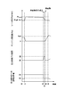
次に、上述した内燃機関の制御装置60によって実行されるディーゼルエンジン40の制御の一例について、図4のタイムチャート及び図5の制御フローに基づいて具体的に説明する。
次に、上述した内燃機関の制御装置60によって実行されるディーゼルエンジン40の制御の一例について、図4のタイムチャート及び図5の制御フローに基づいて具体的に説明する。
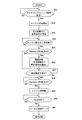
図5の制御フローにおいて、スタート後のステップS11では、所定のアイドリングストップ条件が成立したか否かが判別される(図4のt0~t1の期間)。アイドリングストップ条件が成立すると、ステップS12に進み燃料噴射弁13による燃料噴射を停止してディーゼルエンジン40を停止させるとともに、ステップS13で圧力制御弁12に対して保持電流A1の通電を開始する(図4のt1)。
次いで、ステップS14では所定の再始動条件が成立したか否かが判別される。このステップS14は再始動条件が成立するまで繰り返され(図4のt1~t2の期間)、再始動条件が成立したときにはステップS15に進む。
ステップS15では、検出レール圧Psensorが読み込まれるとともに検出レール圧Psensorが閾値Prail_thr1以上であるか否かが判別される(図4のt2)。検出レール圧Psensorが閾値Prail_thr1未満である場合にはステップS18に進み、そのままの状態でスタータ44を作動させるとともに燃料噴射弁13からの燃料噴射を開始してディーゼルエンジン40を再始動させる。一方、ステップS15において検出レール圧Psensorが閾値Prail_thr1以上である場合には、ステップS16に進んで圧力制御弁12への通電電流を保持電流A1から開弁電流A2に切り替える。これにより、圧力制御弁12が開弁し、これに伴ってレール圧が低下しはじめる。
その後、検出レール圧Psensorが継続的に読み込まれるとともに、検出レール圧Psensorが閾値Prail_thr1未満になるまでは、ステップS17で検出レール圧Psensorが閾値Prail_thr1未満であるか否かが判別される(図4のt2~t3の期間)。そして、検出レール圧Psensorが閾値Prail_thr1未満になったときにステップS18に進み、スタータ44を作動させるとともに燃料噴射弁13からの燃料噴射を開始してディーゼルエンジン40を再始動させる(図4のt3)。
ディーゼルエンジン40が再始動した後は、ステップS19でエンジン回転数Neが所定の回転数Ne0に到達したか否かが判別され(図4のt3~t4の期間)、エンジン回転数Neが所定の回転数Ne0に到達したときにステップS20に進んでレール圧制御モードに移行する(図4のt4)。
このようにしてディーゼルエンジン40の再始動時に圧力制御弁12を開弁することで、燃料噴射弁13からの燃料噴射が開始されて高圧ポンプ5の駆動が開始されるときにはレール圧が低下した状態となる。そのため、加圧室5a内の圧力が著しく高められることがなくなり、プランジャ7を上昇させるための大きな力を要することがなくなる。したがって、カム15とタペット構造体58のローラ54との接触部位の油膜が不十分な状態のままで高圧ポンプ5の駆動系に多大な負荷が与えられることが避けられる。
上述した実施の形態においては、燃料噴射弁に背圧制御に用いられる燃料以外の燃料のリーク通路が設けられておらず、ディーゼルエンジン40の自動停止時にレール圧が低下しにくい構成の蓄圧式燃料噴射装置50を用いた例について説明したが、本発明はこのような蓄圧式燃料噴射装置50を用いる場合に限られるものではない。
燃料噴射弁が背圧制御に用いられる燃料以外の燃料のリーク通路を有しており、ディーゼルエンジンの自動停止時にレール圧が低下する構成の蓄圧式燃料噴射装置を用いる場合においても、ディーゼルエンジン40の再始動条件成立時にレール圧が比較的高い状態である場合に圧力制御弁12が開弁させることで、高圧ポンプの駆動系への負荷が低減される。
燃料噴射弁が背圧制御に用いられる燃料以外の燃料のリーク通路を有しており、ディーゼルエンジンの自動停止時にレール圧が低下する構成の蓄圧式燃料噴射装置を用いる場合においても、ディーゼルエンジン40の再始動条件成立時にレール圧が比較的高い状態である場合に圧力制御弁12が開弁させることで、高圧ポンプの駆動系への負荷が低減される。
[第2の実施の形態]
本発明の第2の実施の形態にかかる内燃機関の制御装置は、圧力制御弁を開弁する制御を内燃機関の再始動条件の成立前に行うように構成されている。以下、第1の実施の形態にかかる内燃機関の制御装置及び内燃機関の制御方法と異なる点を中心に、本実施形態の内燃機関の制御装置及び内燃機関の制御方法について説明する。
本発明の第2の実施の形態にかかる内燃機関の制御装置は、圧力制御弁を開弁する制御を内燃機関の再始動条件の成立前に行うように構成されている。以下、第1の実施の形態にかかる内燃機関の制御装置及び内燃機関の制御方法と異なる点を中心に、本実施形態の内燃機関の制御装置及び内燃機関の制御方法について説明する。
1.制御装置
本実施形態のディーゼルエンジン40の制御装置は、基本的には第1の実施の形態にかかる内燃機関の制御装置60と同様に構成されるが、アイドリングストップ制御による自動停止時に間もなく再始動条件が成立することを判断してあらかじめ圧力制御弁を開弁させるための機能が再始動条件成立検出部及びレール圧判定部に付加されている。
本実施形態のディーゼルエンジン40の制御装置は、基本的には第1の実施の形態にかかる内燃機関の制御装置60と同様に構成されるが、アイドリングストップ制御による自動停止時に間もなく再始動条件が成立することを判断してあらかじめ圧力制御弁を開弁させるための機能が再始動条件成立検出部及びレール圧判定部に付加されている。
本実施形態の制御装置において、再始動条件成立検出部は基本的に第1の実施の形態の制御装置における再始動条件成立検出部と同様の機能を有しているが、さらに、複数ある再始動条件のうちの一部が成立したときに再始動条件が間もなく成立すると判断し、再始動条件成立予備信号をレール圧判定部に対して送信するように設定されている。
具体的には、第1の実施の形態で例示したような複数の再始動条件のうち、例えば、ギアセンサの検出位置がニュートラル状態から解除されることは、アクセルペダルが踏まれることよりも前の段階に行われる場合が多い。再始動条件成立検出部は、このような再始動条件が間もなく成立すると判断しうる情報を検出したときに、再始動条件成立予備信号をレール圧判定部に対して送る。再始動条件が間もなく成立すると判断するための情報は上述した例に限られるものでない。
そして、レール圧判定部では、再始動条件成立検出部からの再始動条件成立予備信号を受信すると、検出レール圧Psensorが所定の閾値Prail_thr1以上であるか否かを判定し、検出レール圧Psensorが閾値Prail_thr1以上である場合には、圧力制御弁12を開かせるための指示を圧力制御弁制御部75に対して送る。その結果、再始動条件の成立前に圧力制御弁12が開弁され、これに伴ってレール圧が低下し始める。したがって、再始動条件成立時にはレール圧が閾値Prail_thr1未満になるため、あるいは、再始動条件成立時にはレール圧が閾値Prail_thr1以上であったとしてもその後レール圧が閾値Prail_thr1となるまでの時間が短縮されるため、再始動前の時間が短縮される。
2.内燃機関の制御方法の具体的フロー
次に、上述した本実施形態の制御装置によって実行されるディーゼルエンジン40の制御の一例について、図6のタイムチャート及び図7の制御フローに基づいて具体的に説明する。
次に、上述した本実施形態の制御装置によって実行されるディーゼルエンジン40の制御の一例について、図6のタイムチャート及び図7の制御フローに基づいて具体的に説明する。
図7の制御フローにおいて、スタート後のステップS51では、所定のアイドリングストップ条件が成立したか否かが判別される(図6のt0~t1の期間)。アイドリングストップ条件が成立すると、ステップS52に進み燃料噴射弁13による燃料噴射を停止してディーゼルエンジン40を停止させるとともに、ステップS53で圧力制御弁12に対して保持電流A1の通電を開始する(図6のt1)。
次いで、ステップS54ではディーゼルエンジン40が間もなく再始動されるか否かが判別される。このステップS54は再始動条件成立予備信号が検出されるまで繰り返され(図6のt1~t2の期間)、ディーゼルエンジン40が間もなく再始動されると判定されたときにはステップS55に進む。
ステップS55では、検出レール圧Psensorが読み込まれるとともに検出レール圧Psensorが閾値Prail_thr1以上であるか否かが判別される(図6のt2)。検出レール圧Psensorが閾値Prail_thr1未満である場合にはそのままステップS57に進む。一方、検出レール圧Psensorが閾値Prail_thr1以上である場合には、ステップS56に進んで圧力制御弁12への通電電流を保持電流A1から開弁電流A2に切り替えた後にステップS57に進む。圧力制御弁12に開弁電流A2が供給されることにより圧力制御弁12が開弁し、これに伴ってレール圧が低下しはじめる。
ステップS57では、再始動条件成立までの間、再始動条件が成立したか否かの判別が繰り替えされ(図6のt2~t3の期間)、再始動条件が成立するとステップS58に進み、検出レール圧Psensorが閾値Prail_thr1未満になっているか否かが判別される(図6のt3)。検出レール圧Psensorが閾値Prail_thr1未満になっているときにはステップS59に進み、スタータ44を作動させるとともに燃料噴射弁13からの燃料噴射を開始してディーゼルエンジン40を再始動させる(図6のt4)。一方、検出レール圧Psensorが閾値Prail_thr1未満になるまで低下していない場合には、検出レール圧Psensorが閾値Prail_thr1未満になるまでこのステップS58が繰り返される(図6のt3~t4の期間)。
ディーゼルエンジン40が再始動した後は、ステップS60でエンジン回転数Neが所定の回転数Ne0に到達したか否かが判別され(図6のt4~t5の期間)、エンジン回転数Neが所定の回転数Ne0に到達したときにステップS61に進んでレール圧制御モードに移行する(図6の時点t5)。
このようにしてディーゼルエンジン40の再始動条件成立前から圧力制御弁12を開弁することで、再始動条件が成立するまでの間にレール圧を低下させることができる。そのため、再始動条件成立時から再始動が許可されるまでの時間が短縮され、ディーゼルエンジン40の再始動性が高められる。また、燃料噴射弁13からの燃料噴射が開始されて高圧ポンプ5の駆動が開始されるときにはレール圧が低下した状態となっているため、加圧室5a内の圧力が著しく高められることがなくなり、プランジャ7を上昇させるための大きな力を要することがなくなる。したがって、カム15とタペット構造体58のローラ54との接触部位の油膜が不十分な状態のままで高圧ポンプ5の駆動系に多大な負荷が与えられることが避けられる。
Claims (4)
- 燃料噴射弁が接続されたコモンレールと、前記コモンレールに燃料を圧送する高圧ポンプと、前記コモンレールから排出される前記燃料の流量を調節する圧力制御弁と、を備えた蓄圧式燃料噴射装置によって内燃機関の制御を行うための制御装置であって、アイドリングストップ制御を実行可能な内燃機関の制御装置において、
所定のアイドリングストップ条件が成立したことを検出するとともに前記内燃機関を自動停止させるよう指示を出力するアイドリングストップ条件成立検出部と、
前記内燃機関の自動停止中に所定の再始動条件が成立したことを検出するとともに前記内燃機関を再始動させるよう指示を出力する再始動条件成立検出部と、
前記コモンレール内の圧力を検出するレール圧検出部と、
前記再始動条件の成立時に前記コモンレール内の圧力が所定の閾値以上となるときには、前記内燃機関を再始動させる前に前記圧力制御弁を開弁する圧力制御弁制御部と、
を備えることを特徴とする内燃機関の制御装置。 - 前記閾値が、前記高圧ポンプから前記高圧ポンプの駆動系への許容される負荷に基づく値であることを特徴とする請求項1に記載の内燃機関の制御装置。
- 前記再始動条件成立検出部は、前記再始動条件の成立前に前記再始動条件が間もなく成立することを検出し、
前記圧力制御弁制御部は、前記再始動条件が間もなく成立することが検出されたときであって前記コモンレール内の圧力が前記閾値以上となっているときに前記圧力制御弁を開弁することを特徴とする請求項1又は2に記載の内燃機関の制御装置。 - 前記再始動条件の成立後に前記コモンレール内の圧力が前記閾値未満となったときに前記内燃機関を再始動させるレール圧判定部を備えることを特徴とする請求項1~3のいずれか一項に記載の内燃機関の制御装置。
Priority Applications (2)
| Application Number | Priority Date | Filing Date | Title |
|---|---|---|---|
| JP2011537150A JP5314156B2 (ja) | 2009-10-23 | 2010-03-15 | 内燃機関の制御装置 |
| EP10824679.4A EP2492480B1 (en) | 2009-10-23 | 2010-03-15 | Control device for internal combustion engine |
Applications Claiming Priority (2)
| Application Number | Priority Date | Filing Date | Title |
|---|---|---|---|
| JP2009244399 | 2009-10-23 | ||
| JP2009-244399 | 2009-10-23 |
Publications (1)
| Publication Number | Publication Date |
|---|---|
| WO2011048827A1 true WO2011048827A1 (ja) | 2011-04-28 |
Family
ID=43900071
Family Applications (1)
| Application Number | Title | Priority Date | Filing Date |
|---|---|---|---|
| PCT/JP2010/054317 WO2011048827A1 (ja) | 2009-10-23 | 2010-03-15 | 内燃機関の制御装置 |
Country Status (3)
| Country | Link |
|---|---|
| EP (1) | EP2492480B1 (ja) |
| JP (1) | JP5314156B2 (ja) |
| WO (1) | WO2011048827A1 (ja) |
Cited By (5)
| Publication number | Priority date | Publication date | Assignee | Title |
|---|---|---|---|---|
| JP2011132872A (ja) * | 2009-12-24 | 2011-07-07 | Denso Corp | 燃料圧力制御装置 |
| WO2012059267A1 (de) * | 2010-11-05 | 2012-05-10 | Robert Bosch Gmbh | Kraftstoffeinspritzsystem einer brennkraftmaschine |
| JP2012237224A (ja) * | 2011-05-11 | 2012-12-06 | Bosch Corp | 蓄圧式燃料噴射装置の制御装置及び制御方法並びに蓄圧式燃料噴射装置 |
| CN104948310A (zh) * | 2014-03-31 | 2015-09-30 | 福特环球技术公司 | 高压泵的快速零流量润滑方法 |
| JP2021021387A (ja) * | 2019-07-30 | 2021-02-18 | 株式会社デンソー | 燃料噴射システムの制御装置 |
Families Citing this family (2)
| Publication number | Priority date | Publication date | Assignee | Title |
|---|---|---|---|---|
| DE102015203348B3 (de) * | 2015-02-25 | 2016-02-18 | Ford Global Technologies, Llc | Verfahren zum Betrieb einer Common-Rail-Einspritzanordnung für eine Brennkraftmaschine mit Stopp-Start-System |
| DE102015220098B3 (de) | 2015-10-15 | 2017-02-16 | Continental Automotive Gmbh | Verfahren und Vorrichtung zum Betreiben einer Brennkraftmaschine mit einem Hochdruck-Kraftstoffeinspritzsystem |
Citations (5)
| Publication number | Priority date | Publication date | Assignee | Title |
|---|---|---|---|---|
| JP2004324440A (ja) * | 2003-04-22 | 2004-11-18 | Toyota Motor Corp | ディーゼルエンジン制御装置 |
| WO2006004101A1 (ja) * | 2004-07-06 | 2006-01-12 | Bosch Corporation | ディーゼルエンジンの液化ガス燃料供給装置 |
| JP2006161716A (ja) * | 2004-12-08 | 2006-06-22 | Denso Corp | コモンレール式燃料噴射装置 |
| JP2007092717A (ja) * | 2005-09-30 | 2007-04-12 | Toyota Motor Corp | 内燃機関用燃料供給装置 |
| JP2008163796A (ja) | 2006-12-27 | 2008-07-17 | Mitsubishi Fuso Truck & Bus Corp | 内燃機関の制御装置 |
Family Cites Families (11)
| Publication number | Priority date | Publication date | Assignee | Title |
|---|---|---|---|---|
| JP3317202B2 (ja) * | 1997-08-04 | 2002-08-26 | トヨタ自動車株式会社 | 蓄圧式エンジンの燃料噴射制御装置 |
| GB2332241B (en) * | 1997-12-11 | 2001-12-19 | Denso Corp | Accumulator fuel injection system for diesel engine of automotive vehicles |
| JP2000136763A (ja) * | 1998-11-04 | 2000-05-16 | Unisia Jecs Corp | 燃料噴射制御装置 |
| JP4635351B2 (ja) * | 2001-02-28 | 2011-02-23 | トヨタ自動車株式会社 | 内燃機関の燃料供給制御装置 |
| JP2005147019A (ja) * | 2003-11-17 | 2005-06-09 | Mitsubishi Electric Corp | 筒内噴射型内燃機関の燃圧制御装置 |
| DE102007035824A1 (de) * | 2007-07-31 | 2009-02-05 | Robert Bosch Gmbh | Druckhaltefunktion bei Vollhybridantrieb |
| JP2009079514A (ja) * | 2007-09-26 | 2009-04-16 | Denso Corp | 筒内噴射式内燃機関の燃圧制御装置 |
| JP2009079564A (ja) * | 2007-09-27 | 2009-04-16 | Denso Corp | 内燃機関の高圧ポンプ制御装置 |
| FR2924177A3 (fr) * | 2007-11-26 | 2009-05-29 | Renault Sas | Procede et dispositif d'amelioration du demarrage direct d'un moteur a combustion interne equipe d'un systeme de "stop&start" |
| JP2010261335A (ja) * | 2009-04-30 | 2010-11-18 | Hitachi Automotive Systems Ltd | 筒内噴射式エンジンの制御装置 |
| JP5131265B2 (ja) * | 2009-12-24 | 2013-01-30 | 株式会社デンソー | 燃料圧力制御装置 |
-
2010
- 2010-03-15 EP EP10824679.4A patent/EP2492480B1/en not_active Not-in-force
- 2010-03-15 JP JP2011537150A patent/JP5314156B2/ja not_active Expired - Fee Related
- 2010-03-15 WO PCT/JP2010/054317 patent/WO2011048827A1/ja active Application Filing
Patent Citations (5)
| Publication number | Priority date | Publication date | Assignee | Title |
|---|---|---|---|---|
| JP2004324440A (ja) * | 2003-04-22 | 2004-11-18 | Toyota Motor Corp | ディーゼルエンジン制御装置 |
| WO2006004101A1 (ja) * | 2004-07-06 | 2006-01-12 | Bosch Corporation | ディーゼルエンジンの液化ガス燃料供給装置 |
| JP2006161716A (ja) * | 2004-12-08 | 2006-06-22 | Denso Corp | コモンレール式燃料噴射装置 |
| JP2007092717A (ja) * | 2005-09-30 | 2007-04-12 | Toyota Motor Corp | 内燃機関用燃料供給装置 |
| JP2008163796A (ja) | 2006-12-27 | 2008-07-17 | Mitsubishi Fuso Truck & Bus Corp | 内燃機関の制御装置 |
Non-Patent Citations (1)
| Title |
|---|
| See also references of EP2492480A4 * |
Cited By (9)
| Publication number | Priority date | Publication date | Assignee | Title |
|---|---|---|---|---|
| JP2011132872A (ja) * | 2009-12-24 | 2011-07-07 | Denso Corp | 燃料圧力制御装置 |
| WO2012059267A1 (de) * | 2010-11-05 | 2012-05-10 | Robert Bosch Gmbh | Kraftstoffeinspritzsystem einer brennkraftmaschine |
| JP2013545015A (ja) * | 2010-11-05 | 2013-12-19 | ローベルト ボッシュ ゲゼルシャフト ミット ベシュレンクテル ハフツング | 内燃機関の燃料噴射システム |
| KR101900965B1 (ko) | 2010-11-05 | 2018-09-20 | 로베르트 보쉬 게엠베하 | 내연 기관의 연료 분사 시스템 |
| JP2012237224A (ja) * | 2011-05-11 | 2012-12-06 | Bosch Corp | 蓄圧式燃料噴射装置の制御装置及び制御方法並びに蓄圧式燃料噴射装置 |
| CN104948310A (zh) * | 2014-03-31 | 2015-09-30 | 福特环球技术公司 | 高压泵的快速零流量润滑方法 |
| CN104948310B (zh) * | 2014-03-31 | 2019-11-08 | 福特环球技术公司 | 高压泵的快速零流量润滑方法 |
| JP2021021387A (ja) * | 2019-07-30 | 2021-02-18 | 株式会社デンソー | 燃料噴射システムの制御装置 |
| JP7226173B2 (ja) | 2019-07-30 | 2023-02-21 | 株式会社デンソー | 燃料噴射システムの制御装置 |
Also Published As
| Publication number | Publication date |
|---|---|
| JP5314156B2 (ja) | 2013-10-16 |
| EP2492480A1 (en) | 2012-08-29 |
| JPWO2011048827A1 (ja) | 2013-03-07 |
| EP2492480B1 (en) | 2015-11-25 |
| EP2492480A4 (en) | 2014-01-01 |
Similar Documents
| Publication | Publication Date | Title |
|---|---|---|
| JP5314156B2 (ja) | 内燃機関の制御装置 | |
| JP4297129B2 (ja) | 内燃機関の始動制御装置 | |
| JP4179333B2 (ja) | 内燃機関の始動制御装置 | |
| JP5131265B2 (ja) | 燃料圧力制御装置 | |
| US7801672B2 (en) | After-stop fuel pressure control device of direct injection engine | |
| JP4045594B2 (ja) | 蓄圧式燃料噴射装置 | |
| JP2012087652A (ja) | 筒内噴射式内燃機関のフェールセーフ制御装置 | |
| JP5464649B2 (ja) | 内燃機関の制御装置 | |
| JP2009079514A (ja) | 筒内噴射式内燃機関の燃圧制御装置 | |
| JP2011127523A (ja) | 蓄圧式燃料噴射装置の制御装置及び制御方法並びに蓄圧式燃料噴射装置 | |
| JP2009079564A (ja) | 内燃機関の高圧ポンプ制御装置 | |
| JP4985674B2 (ja) | 燃料圧力制御装置 | |
| JP4211733B2 (ja) | コモンレール式燃料噴射装置 | |
| JP5140191B2 (ja) | ディーゼルエンジンの制御装置 | |
| JP5477899B2 (ja) | 蓄圧式燃料噴射装置の制御装置及び制御方法並びに蓄圧式燃料噴射装置 | |
| JP4509191B2 (ja) | 筒内噴射エンジンの燃料噴射制御装置 | |
| JP5282468B2 (ja) | ディーゼルエンジンの自動停止制御方法及び自動停止装置 | |
| JP5382870B2 (ja) | 蓄圧式燃料噴射装置の制御装置及び制御方法並びに蓄圧式燃料噴射装置 | |
| JP2017145819A (ja) | 燃料圧力制御装置 | |
| JPH1077892A (ja) | エンジン用蓄圧式燃料供給装置 | |
| JP5441999B2 (ja) | コモンレール圧力の制御装置及び制御方法並びに蓄圧式燃料噴射装置 | |
| WO2011135674A1 (ja) | ディーゼル機関の制御装置 | |
| JP2013164043A (ja) | 内燃機関のアイドリングストップの制御方法 | |
| JPH0730732B2 (ja) | 蓄圧式燃料供給装置 | |
| JP2012145023A (ja) | 内燃機関の高圧燃料供給装置 |
Legal Events
| Date | Code | Title | Description |
|---|---|---|---|
| 121 | Ep: the epo has been informed by wipo that ep was designated in this application |
Ref document number: 10824679 Country of ref document: EP Kind code of ref document: A1 |
|
| WWE | Wipo information: entry into national phase |
Ref document number: 2011537150 Country of ref document: JP |
|
| WWE | Wipo information: entry into national phase |
Ref document number: 2010824679 Country of ref document: EP |