WO2011048827A1 - Dispositif de commande pour moteur à combustion interne - Google Patents
Dispositif de commande pour moteur à combustion interne Download PDFInfo
- Publication number
- WO2011048827A1 WO2011048827A1 PCT/JP2010/054317 JP2010054317W WO2011048827A1 WO 2011048827 A1 WO2011048827 A1 WO 2011048827A1 JP 2010054317 W JP2010054317 W JP 2010054317W WO 2011048827 A1 WO2011048827 A1 WO 2011048827A1
- Authority
- WO
- WIPO (PCT)
- Prior art keywords
- pressure
- internal combustion
- combustion engine
- fuel
- control
- Prior art date
Links
Images


Classifications
-
- F—MECHANICAL ENGINEERING; LIGHTING; HEATING; WEAPONS; BLASTING
- F02—COMBUSTION ENGINES; HOT-GAS OR COMBUSTION-PRODUCT ENGINE PLANTS
- F02M—SUPPLYING COMBUSTION ENGINES IN GENERAL WITH COMBUSTIBLE MIXTURES OR CONSTITUENTS THEREOF
- F02M63/00—Other fuel-injection apparatus having pertinent characteristics not provided for in groups F02M39/00 - F02M57/00 or F02M67/00; Details, component parts, or accessories of fuel-injection apparatus, not provided for in, or of interest apart from, the apparatus of groups F02M39/00 - F02M61/00 or F02M67/00; Combination of fuel pump with other devices, e.g. lubricating oil pump
- F02M63/02—Fuel-injection apparatus having several injectors fed by a common pumping element, or having several pumping elements feeding a common injector; Fuel-injection apparatus having provisions for cutting-out pumps, pumping elements, or injectors; Fuel-injection apparatus having provisions for variably interconnecting pumping elements and injectors alternatively
- F02M63/0225—Fuel-injection apparatus having a common rail feeding several injectors ; Means for varying pressure in common rails; Pumps feeding common rails
- F02M63/023—Means for varying pressure in common rails
- F02M63/0235—Means for varying pressure in common rails by bleeding fuel pressure
- F02M63/025—Means for varying pressure in common rails by bleeding fuel pressure from the common rail
-
- F—MECHANICAL ENGINEERING; LIGHTING; HEATING; WEAPONS; BLASTING
- F02—COMBUSTION ENGINES; HOT-GAS OR COMBUSTION-PRODUCT ENGINE PLANTS
- F02D—CONTROLLING COMBUSTION ENGINES
- F02D41/00—Electrical control of supply of combustible mixture or its constituents
- F02D41/02—Circuit arrangements for generating control signals
- F02D41/04—Introducing corrections for particular operating conditions
- F02D41/06—Introducing corrections for particular operating conditions for engine starting or warming up
- F02D41/062—Introducing corrections for particular operating conditions for engine starting or warming up for starting
- F02D41/065—Introducing corrections for particular operating conditions for engine starting or warming up for starting at hot start or restart
-
- F—MECHANICAL ENGINEERING; LIGHTING; HEATING; WEAPONS; BLASTING
- F02—COMBUSTION ENGINES; HOT-GAS OR COMBUSTION-PRODUCT ENGINE PLANTS
- F02D—CONTROLLING COMBUSTION ENGINES
- F02D41/00—Electrical control of supply of combustible mixture or its constituents
- F02D41/30—Controlling fuel injection
- F02D41/38—Controlling fuel injection of the high pressure type
- F02D41/3809—Common rail control systems
- F02D41/3836—Controlling the fuel pressure
- F02D41/3845—Controlling the fuel pressure by controlling the flow into the common rail, e.g. the amount of fuel pumped
-
- F—MECHANICAL ENGINEERING; LIGHTING; HEATING; WEAPONS; BLASTING
- F02—COMBUSTION ENGINES; HOT-GAS OR COMBUSTION-PRODUCT ENGINE PLANTS
- F02D—CONTROLLING COMBUSTION ENGINES
- F02D41/00—Electrical control of supply of combustible mixture or its constituents
- F02D41/30—Controlling fuel injection
- F02D41/38—Controlling fuel injection of the high pressure type
- F02D41/3809—Common rail control systems
- F02D41/3836—Controlling the fuel pressure
- F02D41/3863—Controlling the fuel pressure by controlling the flow out of the common rail, e.g. using pressure relief valves
-
- F—MECHANICAL ENGINEERING; LIGHTING; HEATING; WEAPONS; BLASTING
- F02—COMBUSTION ENGINES; HOT-GAS OR COMBUSTION-PRODUCT ENGINE PLANTS
- F02M—SUPPLYING COMBUSTION ENGINES IN GENERAL WITH COMBUSTIBLE MIXTURES OR CONSTITUENTS THEREOF
- F02M37/00—Apparatus or systems for feeding liquid fuel from storage containers to carburettors or fuel-injection apparatus; Arrangements for purifying liquid fuel specially adapted for, or arranged on, internal-combustion engines
- F02M37/0047—Layout or arrangement of systems for feeding fuel
- F02M37/0052—Details on the fuel return circuit; Arrangement of pressure regulators
-
- F—MECHANICAL ENGINEERING; LIGHTING; HEATING; WEAPONS; BLASTING
- F02—COMBUSTION ENGINES; HOT-GAS OR COMBUSTION-PRODUCT ENGINE PLANTS
- F02M—SUPPLYING COMBUSTION ENGINES IN GENERAL WITH COMBUSTIBLE MIXTURES OR CONSTITUENTS THEREOF
- F02M63/00—Other fuel-injection apparatus having pertinent characteristics not provided for in groups F02M39/00 - F02M57/00 or F02M67/00; Details, component parts, or accessories of fuel-injection apparatus, not provided for in, or of interest apart from, the apparatus of groups F02M39/00 - F02M61/00 or F02M67/00; Combination of fuel pump with other devices, e.g. lubricating oil pump
- F02M63/02—Fuel-injection apparatus having several injectors fed by a common pumping element, or having several pumping elements feeding a common injector; Fuel-injection apparatus having provisions for cutting-out pumps, pumping elements, or injectors; Fuel-injection apparatus having provisions for variably interconnecting pumping elements and injectors alternatively
- F02M63/0225—Fuel-injection apparatus having a common rail feeding several injectors ; Means for varying pressure in common rails; Pumps feeding common rails
- F02M63/023—Means for varying pressure in common rails
- F02M63/0235—Means for varying pressure in common rails by bleeding fuel pressure
- F02M63/0245—Means for varying pressure in common rails by bleeding fuel pressure between the high pressure pump and the common rail
-
- F—MECHANICAL ENGINEERING; LIGHTING; HEATING; WEAPONS; BLASTING
- F02—COMBUSTION ENGINES; HOT-GAS OR COMBUSTION-PRODUCT ENGINE PLANTS
- F02D—CONTROLLING COMBUSTION ENGINES
- F02D2200/00—Input parameters for engine control
- F02D2200/02—Input parameters for engine control the parameters being related to the engine
- F02D2200/06—Fuel or fuel supply system parameters
- F02D2200/0602—Fuel pressure
-
- F—MECHANICAL ENGINEERING; LIGHTING; HEATING; WEAPONS; BLASTING
- F02—COMBUSTION ENGINES; HOT-GAS OR COMBUSTION-PRODUCT ENGINE PLANTS
- F02D—CONTROLLING COMBUSTION ENGINES
- F02D41/00—Electrical control of supply of combustible mixture or its constituents
- F02D41/02—Circuit arrangements for generating control signals
- F02D41/04—Introducing corrections for particular operating conditions
- F02D41/042—Introducing corrections for particular operating conditions for stopping the engine
-
- F—MECHANICAL ENGINEERING; LIGHTING; HEATING; WEAPONS; BLASTING
- F02—COMBUSTION ENGINES; HOT-GAS OR COMBUSTION-PRODUCT ENGINE PLANTS
- F02M—SUPPLYING COMBUSTION ENGINES IN GENERAL WITH COMBUSTIBLE MIXTURES OR CONSTITUENTS THEREOF
- F02M2200/00—Details of fuel-injection apparatus, not otherwise provided for
- F02M2200/60—Fuel-injection apparatus having means for facilitating the starting of engines, e.g. with valves or fuel passages for keeping residual pressure in common rails
-
- F—MECHANICAL ENGINEERING; LIGHTING; HEATING; WEAPONS; BLASTING
- F02—COMBUSTION ENGINES; HOT-GAS OR COMBUSTION-PRODUCT ENGINE PLANTS
- F02N—STARTING OF COMBUSTION ENGINES; STARTING AIDS FOR SUCH ENGINES, NOT OTHERWISE PROVIDED FOR
- F02N11/00—Starting of engines by means of electric motors
- F02N11/08—Circuits or control means specially adapted for starting of engines
- F02N11/0814—Circuits or control means specially adapted for starting of engines comprising means for controlling automatic idle-start-stop
- F02N11/0818—Conditions for starting or stopping the engine or for deactivating the idle-start-stop mode
Definitions
- the present invention relates to a control device for an internal combustion engine for controlling the internal combustion engine using an accumulator fuel injection device.
- the present invention relates to a control device for an internal combustion engine capable of executing idling stop control.
- an accumulator fuel injection device (common rail system) provided with a common rail for accumulating high-pressure fuel supplied by a high-pressure pump is known. It is used.
- a plurality of fuel injection valves are connected to the common rail, and various fuels are controlled by controlling the valve opening timing and valve opening time of each fuel injection valve while high-pressure fuel is supplied to each fuel injection valve. Fuel is injected into the cylinder of the internal combustion engine in an injection pattern.
- the high pressure pump is usually configured to be driven by the power of the internal combustion engine.
- the camshaft of the high-pressure pump is connected to the drive shaft of the internal combustion engine via a gear, and the high-pressure pump also operates during operation of the internal combustion engine, while the high-pressure pump also stops when the internal combustion engine stops. .
- the pressure in the common rail greatly affects fuel injection characteristics or combustibility.
- rail pressure control method there is a control method in which the flow rate of high-pressure fuel discharged from the common rail is adjusted by a pressure control valve provided in the common rail.
- a control device for an internal combustion engine that can shorten the stop time during the idling stop control of the internal combustion engine and can reliably improve the restartability. More specifically, when the internal combustion engine is automatically stopped by idling stop control, the discharge flow rate of the high-pressure pump is increased and the load of the internal combustion engine is adjusted to stop the crank angle at a predetermined crank angle suitable for restarting.
- a control device for an internal combustion engine is disclosed in which fuel injection is started simultaneously with the starter operation at the time of restart (see Patent Document 1).
- the compression ratio in the engine is sufficient to improve the restartability from the automatic stop state of the engine, and the fuel injection by the pressure accumulation type fuel injection device is possible. Is a factor. Of these two factors, whether or not the compression ratio is sufficient is a problem on the engine side, and whether or not fuel injection is possible is a problem on the accumulator fuel injection apparatus side. Whether or not fuel injection is possible in the accumulator type fuel injection device depends on whether or not the rail pressure is secured to a pressure higher than the pressure at which fuel can be normally injected (hereinafter referred to as “injectable pressure”). Therefore, in order to improve the restartability of the internal combustion engine, control may be performed so that the rail pressure is maintained at a high level even during the automatic stop of the internal combustion engine by the idling stop control.
- the target value of the rail pressure when starting to maintain the rail pressure during automatic stop is set to a value higher than the injectable pressure.
- the driving torque generated when the high-pressure pump starts to move is remarkably increased, which greatly increases the driving system of the high-pressure pump. Will give a heavy load. Specifically, when the internal combustion engine is restarted, the number of revolutions is rapidly increasing, and when the rail pressure is higher in such a state, rail pressure control by the pressure control valve is started. Then, rail pressure overshoot or undershoot may occur, and the rail pressure may become uncontrollable.
- the rail pressure control is not normally performed until the rotational speed of the internal combustion engine reaches a predetermined rotational speed.
- the flow control valve for adjusting the amount of fuel supplied to is opened, and the pressure control valve provided on the common rail is closed.
- a fuel discharge valve that opens when the pressure in the pressurizing chamber exceeds the sum of the rail pressure and the set force of the valve spring is provided between the pressurizing chamber of the high-pressure pump and the common rail. Therefore, if the fuel is supplied to the pressurizing chamber of the high-pressure pump when the internal combustion engine is restarted and the high-pressure pump is driven in a state where the rail pressure is high, the pressure in the pressurizing chamber is maintained until the fuel discharge valve is opened. Is significantly higher. As a result, a large force for pushing up the plunger for pressurizing the fuel is required, and a great load is generated on the drive system of the high-pressure pump.
- an object of the present invention is to provide a control device for an internal combustion engine that can reduce a load applied to a drive system of a high-pressure pump when the internal combustion engine is restarted from an automatic stop state.
- an accumulator fuel injection apparatus comprising: a common rail connected to a fuel injection valve; a high-pressure pump that pumps fuel to the common rail; and a pressure control valve that adjusts the flow rate of fuel discharged from the common rail.
- the control device for controlling the internal combustion engine by means of the control device for the internal combustion engine capable of executing the idling stop control detects that a predetermined idling stop condition is satisfied and instructs the internal combustion engine to automatically stop.
- An idling stop condition establishment detection unit that outputs a restart condition establishment detection unit that detects that a predetermined restart condition is established during automatic stop of the internal combustion engine and outputs an instruction to restart the internal combustion engine; Rail pressure detector that detects the pressure in the common rail, and the pressure in the common rail when the restart condition is met And a pressure control valve control unit that opens the pressure control valve before restarting the internal combustion engine when the predetermined threshold value is exceeded.
- the threshold value is preferably a value based on an allowable load from the high pressure pump to the drive system of the high pressure pump.
- the restart condition establishment detection unit detects that the restart condition is about to be established before the restart condition is established, and the pressure control valve control unit It is preferable to open the pressure control valve when it is detected that the start condition is about to be established soon and the pressure in the common rail is equal to or higher than the threshold value.
- control device for an internal combustion engine of the present invention, it is preferable to include a rail pressure determination unit that restarts the internal combustion engine when the pressure in the common rail becomes less than a threshold value after the restart condition is satisfied.
- the control device for an internal combustion engine of the present invention when the rail pressure is maintained in an unnecessarily high state when the internal combustion engine is restarted from the automatic stop state by the idling stop control, before the internal combustion engine is restarted.
- the pressure control valve is opened, and the rail pressure is forcibly reduced. Therefore, since the internal combustion engine is not restarted while the rail pressure is higher than necessary, the pressure in the pressurizing chamber is prevented from significantly increasing, and the load on the drive system of the high pressure pump is reduced.
- 1 is an overall view showing a configuration example of an accumulator fuel injection device. It is a figure for demonstrating the structural example of a high pressure pump. It is a block diagram for demonstrating the structural example of the control apparatus concerning the 1st Embodiment of this invention. It is a time chart for demonstrating the control method performed by the control apparatus of 1st Embodiment. It is a control flow for demonstrating the control method performed by the control apparatus of 1st Embodiment. It is a time chart for demonstrating the control method performed by the control apparatus of 2nd Embodiment. It is a control flow for demonstrating the control method performed by the control apparatus of 2nd Embodiment.
- FIG. 1 shows a configuration example of an accumulator fuel injection device 50 used for controlling an internal combustion engine.
- the accumulator fuel injection device 50 is a device for injecting fuel into a cylinder of a diesel engine 40 mounted on a vehicle, and includes a fuel tank 1, a low pressure pump 2, a flow control valve 8, and a high pressure pump. 5, a common rail 10, a pressure control valve 12, a fuel injection valve 13, a control device 60 and the like as main elements.
- the diesel engine 40 is provided with a rotational speed sensor 45 used for detecting the rotational speed of the engine and a starter 44 for forcibly rotating the drive shaft at the time of starting.
- the low pressure pump 2 and the pressurizing chamber 5a of the high pressure pump 5 are connected by low pressure fuel passages 18a and 18b.
- the pressurizing chamber 5a of the high pressure pump 5 and the common rail 10, and the common rail 10 and the fuel injection valve 13 are respectively high pressure fuel.
- the passages 37 and 39 are connected.
- return passages 30a to 30c for returning excess fuel not injected from the fuel injection valve 13 to the fuel tank 1 are connected to the high pressure pump 5, the common rail 10, the fuel injection valve 13, and the like.
- a flow control valve 8 is provided in the middle of the low-pressure fuel passage 18b in the high-pressure pump 5.
- the flow rate control valve 8 is, for example, an electromagnetic proportional flow rate control valve in which the stroke amount of the valve body is variable depending on the supply current value and the area of the fuel passage is adjustable, and the fuel sent to the pressurizing chamber 5a. It is used to adjust the flow rate.
- the flow rate control valve 8 used in the present embodiment is configured as a normally open flow rate control valve in which a fuel flow path is fully opened in a non-energized state. However, it may be a normally closed flow control valve in which the fuel flow path is fully closed in a non-energized state.
- the fuel passage branched from the low-pressure fuel passage 18b on the upstream side of the flow control valve 8 is provided with a pressure adjusting valve 14 arranged in parallel with the flow control valve 8.
- the pressure regulating valve 14 is connected to a return passage 30 a that communicates with the fuel tank 1.
- the pressure regulating valve 14 is an overflow valve that is opened when the differential pressure between the front and rear, that is, the pressure difference between the pressure in the low pressure fuel passage 18b and the pressure in the return passage 30a exceeds a predetermined value. ing. Therefore, in a state where the fuel is being pumped by the low-pressure pump 2, the pressure in the low-pressure fuel passages 18a and 18b is adjusted to be larger than the pressure in the return passage 30a by a predetermined differential pressure.
- the low-pressure pump 2 sucks up the fuel in the fuel tank 1 and pumps it, and supplies the fuel to the pressurizing chamber 5a of the high-pressure pump 5 through the low-pressure fuel passages 18a and 18b.
- a low-pressure pump 2 shown in FIG. 1 is an in-tank electric pump provided in a fuel tank 1 and is driven by a voltage supplied from a battery to pump fuel. However, the low pressure pump 2 may be provided outside the fuel tank 1, or may be a gear pump that is driven by the power of the diesel engine 40.
- the high-pressure pump 5 pressurizes fuel introduced into the pressurizing chamber 5 a by the low-pressure pump 2 through the fuel intake valve 6 by the plunger 7, and supplies high-pressure fuel to the common rail through the fuel discharge valve 9 and the high-pressure fuel passage 37. 10 to pump.
- the fuel discharge valve 9 has a check valve structure in which the sealing performance is improved as the rail pressure located on the discharge side is higher.
- the cam 15 that drives the high-pressure pump 5 is fixed to a cam shaft that is connected to the drive shaft of the diesel engine 40 via a gear.
- the high-pressure pump 5 shown in FIG. 1 includes two plungers 7. The two plungers 7 are pushed up by cams 15 and fuel is pressurized in the two pressurizing chambers 5a to the common rail 10. High pressure fuel is pumped.
- the high-pressure pump 5 of the pressure-accumulation fuel injection device 50 of this embodiment has a fuel-lubricated configuration that uses fuel for injection as lubricating oil, and the fuel that is sent into the high-pressure pump 5 via the low-pressure fuel passage 18a is Once it flows into the cam chamber 16, it is further sent to the pressurizing chamber 5a via the low pressure fuel passage 18b.
- the common rail 10 accumulates high-pressure fuel pumped from the high-pressure pump 5 and supplies high-pressure fuel to the plurality of fuel injection valves 13 connected via the high-pressure fuel passage 39.
- the common rail 10 is provided with a pressure control valve 12 and a pressure sensor 21.
- the pressure sensor 21 is a known pressure sensor such as a piezoelectric element sensor or a semiconductor sensor.
- the pressure control valve 12 is, for example, an electromagnetic proportional control valve in which the stroke amount of the valve body is variable depending on the supply current value and the area of the fuel passage is adjustable. The amount of power supplied to the pressure control valve 12 is controlled according to the target rail pressure and the required injection amount, and the rail pressure is adjusted by adjusting the flow rate of the high-pressure fuel discharged from the common rail 10 to the return passage 30b. .
- the pressure control valve 12 used in the present embodiment is configured as a normally open pressure control valve in which a fuel flow path is fully opened in a non-energized state. However, it may be a normally closed pressure control valve in which the fuel flow path is fully closed in a non-energized state.
- the fuel injection valve 13 connected to the common rail 10 includes a nozzle body provided with an injection hole and a nozzle needle that opens and closes the injection hole by advancing and retreating.
- the injection hole is closed by applying a back pressure to the rear end side of the nozzle needle, while the injection hole is opened by releasing the applied back pressure, and the high pressure supplied from the common rail 10.
- the fuel is injected into the cylinder of the diesel engine.
- the fuel injection valve 13 is capable of normal fuel injection when the rail pressure is equal to or higher than a predetermined injectable pressure.
- a piezo injector provided with a piezo element as back pressure control means or an electromagnetically controlled fuel injection valve provided with an electromagnetic solenoid as back pressure control means is used.
- a piezo injector is used, and this piezo injector employs a structure in which fuel does not easily leak into the return passage 30c other than a passage for releasing back pressure.
- FIG. 2 shows an example of a specific configuration of the high pressure pump 5.
- the high-pressure pump 5 includes a pump housing 51, a cylinder head 52 mounted in a cylindrical space 51a of the pump housing 51, a plunger 7 slidably held by a cylinder 52a of the cylinder head 52, and both ends of the cylinder head 52 and A spring 55, which is locked to the spring seat 59 and biases the plunger 7 downward, is interposed between the plunger 7 and the cam 15, and is used to push up the plunger 7 while centering as the cam 15 rotates.
- a tappet structure 58 is used to push up the plunger 7 while centering as the cam 15 rotates.
- the fuel intake valve 6 is disposed in the upper opening of the cylinder 52a of the cylinder head 52, and the fuel discharge valve 9 is disposed in the lateral direction with respect to the axial direction of the cylinder 52a via the fuel discharge passage 52b. ing.
- the flow control valve 8 and the pressure adjustment valve 14 provided in the high pressure pump 5 are not shown.
- a part of the cylinder 52a of the cylinder head 52 is closed by the inner peripheral surface of the cylinder head 52, the plunger 7, the fuel intake valve 6, and the fuel discharge valve 9, and is configured as a pressurizing chamber 5a. Yes.
- the fuel that has flowed into the pressurizing chamber 5a through the fuel intake valve 6 is pressurized in the pressurizing chamber 5a by the plunger 7 that is pushed up as the cam 15 rotates.
- the pressure in the pressurizing chamber 5a exceeds the sum of the set force of the valve spring of the fuel discharge valve 9 and the rail pressure, and the fuel discharge valve 9 is pushed open, so that pressurized fuel is pumped toward the common rail.
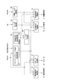
- FIG. 3 shows functional parts of the control device 60 of the diesel engine 40 according to the present embodiment that are related to the control performed when the diesel engine 40 is restarted from the automatic stop state by the idling stop control.
- a configuration example represented by blocks is shown.
- the control device 60 includes an idling stop control unit 63 including an idling stop condition establishment detection unit 61 and a restart condition establishment detection unit 62, a target rail pressure calculation unit 65, a rail pressure detection unit 67, and a rail pressure determination unit 69.
- the control device 60 is configured around a microcomputer having a known configuration, and each unit is realized by executing a program by the microcomputer. Further, the control device 60 includes a RAM (Random) (not shown) for storing calculation results and detection results at each unit.
- a storage means such as an access memory is provided.
- the idling stop control unit 63 issues an instruction to stop fuel injection and stop the diesel engine 40 when the idling stop condition establishment detection unit 61 detects the establishment of a predetermined idling stop condition. This is sent to the fuel injection valve control unit 71. At this time, the idling stop control unit 63 sends an instruction for shutting off the energization to the flow control valve 8 to the flow control valve control unit 73. In addition, the idling stop control unit 63 sends an instruction for energizing the pressure control valve 12 with a predetermined holding current A1 to the pressure control valve control unit 75 in order to maintain the rail pressure at a predetermined pressure.
- the idling stop control unit 63 resumes fuel injection when the restart condition establishment detection unit 62 detects that the predetermined restart condition is established while the diesel engine 40 is automatically stopped by the idling stop control. Then, an instruction for restarting the diesel engine 40 is sent to the fuel injection valve control unit 71 and the starter control unit 77. Further, the idling stop control unit 63 transmits the establishment of the restart condition to the rail pressure determination unit 69 when the restart condition is established.
- the idling stop condition detected by the idling stop condition establishment detection unit 61 is, for example, that the engine switch Sw is in an on state, the detection position Sg of the gear sensor indicates neutral, and the detection position Sb of the brake pedal sensor is At least one of the state in which the pedal is depressed, the rotational speed Ne of the diesel engine 40 is equal to or lower than a predetermined threshold, and the state where the vehicle speed V is 0 continues for a predetermined time or more.
- the condition can be that more than one condition is met, but is not limited to this.
- the restart condition detected by the restart condition establishment detection unit 62 is that the detection position Sg of the gear sensor is released from the neutral state during the automatic stop of the diesel engine 40, the accelerator pedal Acc is stepped on, etc.
- the present invention is not limited to this condition.
- the fuel injection valve control unit 71 calculates the target fuel injection amount Qtgt based on the engine speed Ne, the accelerator operation amount Acc, and the like, and the fuel injection valve 13 corresponding to the target fuel injection amount Qtgt. And a control signal is output to the fuel injection valve 13.
- the fuel injection valve control unit 71 stops fuel injection when a signal indicating that the idling stop condition is satisfied is transmitted from the idling stop control unit 63, and resumes fuel injection when a signal indicating that the restart condition is satisfied is transmitted. To do.
- the fuel injection valve control unit 71 of the control device 60 of the present embodiment instructs the start permission from the rail pressure determination unit 69 even when the establishment of the restart condition is transmitted after the automatic stop by the idling stop control. It is set so that the fuel injection control is not resumed until is received.
- the starter control unit 77 operates the starter 44 when the diesel engine 40 is started, and performs control for forcibly rotating the drive shaft to compress the inside of the cylinder.
- the starter control unit 77 of the control device 60 permits the start permission from the rail pressure determination unit 69 even when the establishment of the restart condition is transmitted after the diesel engine 40 is automatically stopped by the idling stop control.
- the starter 44 is set not to operate until the instruction is received.
- Target rail pressure calculation unit 65 calculates the target rail pressure Ptgt based on the engine speed Ne, the accelerator operation amount Acc, and the like, and stores it in the storage unit. Further, the rail pressure detection unit 67 continuously reads the sensor value of the pressure sensor 21 provided in the common rail 10, obtains the detected rail pressure Psensor, and stores it in the storage means.
- the rail pressure determination unit 69 continuously reads the detected rail pressure Psensor and the detected rail pressure Psensor is a predetermined value. It is determined whether or not the threshold is Prail_thr1 or more.
- the threshold value Prail_thr1 is set to a value that does not increase the load on the drive system of the high-pressure pump 5 even when driving of the high-pressure pump 5 is started.
- the threshold value Prail_thr1 is assumed to be larger than the injectable pressure at which normal injection from the fuel injection valve 13 is possible, and when the holding current A1 is energized to the pressure control valve 12 when the diesel engine 40 is automatically stopped by the idling stop control.
- the rail pressure determination unit 69 transmits an instruction signal for opening the pressure control valve 12 to the pressure control valve control unit 75.
- the rail pressure determination unit 69 is set to send a start permission instruction to the fuel injection valve control unit 71 and the starter control unit 77 when the detected rail pressure Psensor is less than the threshold value Prail_thr1.
- the flow rate control valve control unit 73 and the pressure control valve control unit 75 are basically configured so that the detected rail pressure Psensor becomes the target rail pressure Ptgt.
- the energization control of the control valve 8 or the pressure control valve 12 is executed.
- the flow rate control valve control unit 73 controls the flow rate of the fuel supplied to the pressurizing chamber 5a of the high pressure pump 5 by adjusting the opening degree of the flow rate control valve 8, and from the high pressure pump 5 to the common rail 10
- the rail pressure is adjusted by changing the flow rate of the high-pressure fuel pumped.
- the pressure control valve control unit 75 controls the flow rate of the return fuel discharged from the common rail 10 to the return passage 30b by adjusting the opening degree of the pressure control valve 12, thereby adjusting the rail pressure.
- the rail pressure is controlled by the flow rate control valve control unit 73, the pressure control valve control unit 75, or the combination of the two control units depends on the running state of the vehicle and the operating state of the diesel engine 40. It is divided according to. However, when the diesel engine 40 is started, the rail pressure is not controlled until the engine speed Ne detected by the speed sensor 45 reaches the predetermined speed Ne0, and basically the flow control valve 8 is not operated. Is held fully open and the pressure control valve 12 is closed.
- the flow control valve control unit 73 cuts off the power supply to the flow control valve 8. Since the flow control valve 8 of the present embodiment has a normally open configuration, the flow control valve 8 is fully opened when power is cut off when the diesel engine 40 is automatically stopped.
- the pressure control valve control unit 75 when the pressure control valve control unit 75 receives a control instruction accompanying the establishment of the idling stop condition from the idling stop control unit 63, the pressure control valve control unit 75 performs control to continuously energize the pressure control valve 12 with a predetermined holding current A1.
- This holding current A1 is a control value such that the rail pressure is adjusted to a value larger than the injectable pressure, and even when the diesel engine 40 automatically stops for a relatively long time, the rail pressure at the time of restarting is maintained. Is set to such a value that is ensured to be equal to or higher than the injectable pressure.
- the pressure control valve control unit 75 opens the pressure control valve 12 output from the rail pressure determination unit 69 because the rail pressure is equal to or higher than the threshold value Prail_thr1 when the restart condition of the diesel engine 40 is satisfied.
- control is performed to switch the current value to be supplied to the pressure control valve 12 from the holding current A1 to the valve opening current A2.
- the valve opening current A2 is set in advance to a current value such that the rail pressure is less than the threshold value Prail_thr1 and is equal to or greater than the injectable pressure.
- valve opening current A2 When the valve opening current A2 is applied to the pressure control valve 12 in a state where the rail pressure is equal to or higher than the threshold value Prail_thr1, the pressure control valve 12 is opened, and the rail pressure is reduced to be lower than the threshold value Prail_thr1. That is, when the diesel engine 40 is restarted, the pressure control valve 12 is basically closed. However, when the detected rail pressure Psensor when the restart condition is satisfied is equal to or higher than the threshold value Prail_thr1, the valve opening current is supplied to the pressure control valve 12. A2 is energized and the pressure control valve 12 is opened.
- valve opening current A2 is set to a current value such that the rail pressure is less than the threshold value Prail_thr1 and equal to or greater than the injectable pressure, so the rail pressure is reduced to less than the threshold value Prail_thr1.
- the restartability of the diesel engine 40 is not affected.
- the valve opening current A2 supplied to the pressure control valve 12 is not limited to a predetermined value in advance.
- the detected rail pressure Psensor immediately before the diesel engine 40 is automatically stopped by the idling stop control is the threshold value Prail_thr1. If it is less than the value, the current value supplied to the pressure control valve 12 at that time can be set as the valve opening current A2.
- the valve opening current A2 is set in this way, the rail pressure after the valve opening current A2 is supplied can be prevented from becoming less than the injectable pressure.
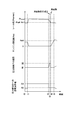
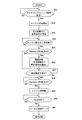
- step S11 after the start, it is determined whether or not a predetermined idling stop condition is satisfied (period t0 to t1 in FIG. 4).
- a predetermined idling stop condition is satisfied, the process proceeds to step S12, the fuel injection by the fuel injection valve 13 is stopped to stop the diesel engine 40, and the energization of the holding current A1 is started to the pressure control valve 12 in step S13 (FIG. 4 t1).
- step S14 it is determined whether or not a predetermined restart condition is satisfied. This step S14 is repeated until the restart condition is satisfied (period t1 to t2 in FIG. 4), and when the restart condition is satisfied, the process proceeds to step S15.
- step S15 the detected rail pressure Psensor is read, and it is determined whether or not the detected rail pressure Psensor is greater than or equal to a threshold value Prail_thr1 (t2 in FIG. 4). If the detected rail pressure Psensor is less than the threshold value Prail_thr1, the process proceeds to step S18, the starter 44 is operated as it is, and fuel injection from the fuel injection valve 13 is started to restart the diesel engine 40. On the other hand, if the detected rail pressure Psensor is greater than or equal to the threshold value Prail_thr1 in step S15, the process proceeds to step S16, and the current supplied to the pressure control valve 12 is switched from the holding current A1 to the valve opening current A2. As a result, the pressure control valve 12 is opened, and the rail pressure begins to decrease accordingly.
- a threshold value Prail_thr1 t2 in FIG. 4
- the detected rail pressure Psensor is continuously read, and it is determined whether or not the detected rail pressure Psensor is less than the threshold value Prail_thr1 in step S17 until the detected rail pressure Psensor becomes less than the threshold value Prail_thr1 (FIG. 4). T2 to t3). Then, when the detected rail pressure Psensor becomes less than the threshold value Prail_thr1, the process proceeds to step S18, where the starter 44 is operated and fuel injection from the fuel injection valve 13 is started to restart the diesel engine 40 (t3 in FIG. 4). ).
- step S19 After the diesel engine 40 is restarted, it is determined in step S19 whether or not the engine speed Ne has reached a predetermined speed Ne0 (period t3 to t4 in FIG. 4). When the rotational speed Ne0 is reached, the process proceeds to step S20 to shift to the rail pressure control mode (t4 in FIG. 4).
- the fuel injection valve is not provided with a fuel leak passage other than the fuel used for back pressure control, and the pressure accumulation type fuel is configured such that the rail pressure does not easily decrease when the diesel engine 40 is automatically stopped.
- the present invention is not limited to the case where such a pressure accumulation type fuel injection device 50 is used. Even when the fuel injection valve has a leak passage for fuel other than the fuel used for back pressure control, and the pressure accumulation type fuel injection device is configured such that the rail pressure decreases when the diesel engine is automatically stopped, the diesel engine 40 When the rail pressure is relatively high when the restart condition is satisfied, the pressure control valve 12 is opened to reduce the load on the drive system of the high-pressure pump.
- the control apparatus for an internal combustion engine according to the second embodiment of the present invention is configured to perform control for opening the pressure control valve before the restart condition of the internal combustion engine is satisfied.
- the control device for an internal combustion engine and the control method for the internal combustion engine of the present embodiment will be described focusing on differences from the control device for the internal combustion engine and the control method for the internal combustion engine according to the first embodiment.
- Control Device for the diesel engine 40 according to the present embodiment is basically configured in the same manner as the control device 60 for the internal combustion engine according to the first embodiment, but will be restarted soon after the automatic stop by the idling stop control.
- a function for determining that the condition is satisfied and opening the pressure control valve in advance is added to the restart condition satisfaction detection unit and the rail pressure determination unit.
- the restart condition establishment detection unit basically has the same function as the restart condition establishment detection unit in the control device of the first embodiment. It is determined that when a part of the start condition is satisfied, the restart condition is determined to be satisfied soon, and a restart condition satisfaction preliminary signal is transmitted to the rail pressure determination unit.
- the release of the detection position of the gear sensor from the neutral state is before the accelerator pedal is depressed. Often done in stages.
- the restart condition establishment detection unit sends a restart condition establishment preliminary signal to the rail pressure determination unit when detecting information that can be determined that such a restart condition will soon be established. Information for determining that the restart condition will soon be satisfied is not limited to the above-described example.
- the rail pressure determination unit receives the restart condition establishment preliminary signal from the restart condition establishment detection unit, it determines whether or not the detected rail pressure Psensor is equal to or greater than a predetermined threshold value Prail_thr1, and the detected rail pressure Psensor is If it is equal to or greater than the threshold value Prail_thr1, an instruction to open the pressure control valve 12 is sent to the pressure control valve control unit 75. As a result, the pressure control valve 12 is opened before the restart condition is satisfied, and the rail pressure starts to decrease accordingly.
- the rail pressure becomes less than the threshold value Prail_thr1, or when the restart condition is satisfied, even if the rail pressure is equal to or higher than the threshold value Prail_thr1, the time until the rail pressure becomes the threshold value Prail_thr1 is shortened thereafter. Therefore, the time before restart is shortened.
- step S51 after the start, it is determined whether or not a predetermined idling stop condition is satisfied (period t0 to t1 in FIG. 6).
- a predetermined idling stop condition is satisfied, the process proceeds to step S52, the fuel injection by the fuel injection valve 13 is stopped and the diesel engine 40 is stopped.
- step S53 the holding of the holding current A1 is started to the pressure control valve 12 (FIG. 6 t1).
- step S54 it is determined whether or not the diesel engine 40 will be restarted soon. This step S54 is repeated until a restart condition satisfaction preliminary signal is detected (period t1 to t2 in FIG. 6), and when it is determined that the diesel engine 40 will be restarted soon, the routine proceeds to step S55.
- step S55 the detected rail pressure Psensor is read, and it is determined whether or not the detected rail pressure Psensor is greater than or equal to a threshold value Prail_thr1 (t2 in FIG. 6). If the detected rail pressure Psensor is less than the threshold value Prail_thr1, the process proceeds directly to step S57. On the other hand, if the detected rail pressure Psensor is greater than or equal to the threshold value Prail_thr1, the process proceeds to step S56, the energization current to the pressure control valve 12 is switched from the holding current A1 to the valve opening current A2, and then the process proceeds to step S57. When the valve opening current A2 is supplied to the pressure control valve 12, the pressure control valve 12 is opened, and the rail pressure begins to decrease accordingly.
- a threshold value Prail_thr1 t2 in FIG. 6
- step S57 the determination as to whether or not the restart condition is satisfied is repeated until the restart condition is satisfied (period t2 to t3 in FIG. 6).
- the process proceeds to step S58 to detect the detection rail. It is determined whether or not the pressure Psensor is less than the threshold value Prail_thr1 (t3 in FIG. 6).
- the process proceeds to step S59, where the starter 44 is operated and fuel injection from the fuel injection valve 13 is started to restart the diesel engine 40 (t4 in FIG. 6).
- this step S58 is repeated until the detected rail pressure Psensor becomes less than the threshold value Prail_thr1 (period t3 to t4 in FIG. 6).
- step S60 After the diesel engine 40 is restarted, it is determined in step S60 whether or not the engine speed Ne has reached a predetermined speed Ne0 (period t4 to t5 in FIG. 6). When the rotational speed Ne0 is reached, the process proceeds to step S61 to shift to the rail pressure control mode (time t5 in FIG. 6).
- the rail pressure can be reduced until the restart condition is satisfied. Therefore, the time from when the restart condition is satisfied until the restart is permitted is shortened, and the restartability of the diesel engine 40 is improved. Further, when the fuel injection from the fuel injection valve 13 is started and the driving of the high pressure pump 5 is started, the rail pressure is in a lowered state, so that the pressure in the pressurizing chamber 5a is not significantly increased. , No large force is required to raise the plunger 7. Therefore, it is possible to avoid applying a great load to the drive system of the high-pressure pump 5 while the oil film at the contact portion between the cam 15 and the roller 54 of the tappet structure 58 is insufficient.
Landscapes
- Engineering & Computer Science (AREA)
- Chemical & Material Sciences (AREA)
- Combustion & Propulsion (AREA)
- Mechanical Engineering (AREA)
- General Engineering & Computer Science (AREA)
- Fuel-Injection Apparatus (AREA)
- Electrical Control Of Air Or Fuel Supplied To Internal-Combustion Engine (AREA)
- Control Of Vehicle Engines Or Engines For Specific Uses (AREA)
Abstract
L'invention concerne un dispositif de commande pour un moteur à combustion interne permettant de réduire une charge appliquée à un système d'entraînement d'une pompe haute pression lors du redémarrage d'un moteur à combustion interne qui a été arrêté automatiquement. Le dispositif de commande pour un moteur à combustion interne permettant une commande d'arrêt au ralenti est doté d'une unité de détection de condition d'arrêt au ralenti qui détecte lorsqu'une condition d'arrêt au ralenti prédéterminée est remplie et émet des instructions pour arrêter automatiquement le moteur à combustion interne, d'une unité de détection de condition de redémarrage qui détecte lorsqu'une condition de redémarrage prédéterminée est remplie pendant la période pendant laquelle le moteur à combustion interne est arrêté automatiquement et émet des instructions pour redémarrer le moteur à combustion interne, d'une unité de détection de pression de rampe pour détecter la pression à l'intérieur d'une rampe commune, et d'une unité de commande de soupape de régulation de pression qui ouvre une soupape de régulation de pression avant le redémarrage du moteur à combustion interne si la pression à l'intérieur de la rampe commune est égale ou supérieure à une valeur seuil prédéterminée lorsque la condition de redémarrage est remplie.
Priority Applications (2)
| Application Number | Priority Date | Filing Date | Title |
|---|---|---|---|
| JP2011537150A JP5314156B2 (ja) | 2009-10-23 | 2010-03-15 | 内燃機関の制御装置 |
| EP10824679.4A EP2492480B1 (fr) | 2009-10-23 | 2010-03-15 | Dispositif de commande pour moteur à combustion interne |
Applications Claiming Priority (2)
| Application Number | Priority Date | Filing Date | Title |
|---|---|---|---|
| JP2009-244399 | 2009-10-23 | ||
| JP2009244399 | 2009-10-23 |
Publications (1)
| Publication Number | Publication Date |
|---|---|
| WO2011048827A1 true WO2011048827A1 (fr) | 2011-04-28 |
Family
ID=43900071
Family Applications (1)
| Application Number | Title | Priority Date | Filing Date |
|---|---|---|---|
| PCT/JP2010/054317 WO2011048827A1 (fr) | 2009-10-23 | 2010-03-15 | Dispositif de commande pour moteur à combustion interne |
Country Status (3)
| Country | Link |
|---|---|
| EP (1) | EP2492480B1 (fr) |
| JP (1) | JP5314156B2 (fr) |
| WO (1) | WO2011048827A1 (fr) |
Cited By (5)
| Publication number | Priority date | Publication date | Assignee | Title |
|---|---|---|---|---|
| JP2011132872A (ja) * | 2009-12-24 | 2011-07-07 | Denso Corp | 燃料圧力制御装置 |
| WO2012059267A1 (fr) * | 2010-11-05 | 2012-05-10 | Robert Bosch Gmbh | Système d'injection de carburant d'un moteur à combustion interne |
| JP2012237224A (ja) * | 2011-05-11 | 2012-12-06 | Bosch Corp | 蓄圧式燃料噴射装置の制御装置及び制御方法並びに蓄圧式燃料噴射装置 |
| CN104948310A (zh) * | 2014-03-31 | 2015-09-30 | 福特环球技术公司 | 高压泵的快速零流量润滑方法 |
| JP2021021387A (ja) * | 2019-07-30 | 2021-02-18 | 株式会社デンソー | 燃料噴射システムの制御装置 |
Families Citing this family (2)
| Publication number | Priority date | Publication date | Assignee | Title |
|---|---|---|---|---|
| DE102015203348B3 (de) * | 2015-02-25 | 2016-02-18 | Ford Global Technologies, Llc | Verfahren zum Betrieb einer Common-Rail-Einspritzanordnung für eine Brennkraftmaschine mit Stopp-Start-System |
| DE102015220098B3 (de) * | 2015-10-15 | 2017-02-16 | Continental Automotive Gmbh | Verfahren und Vorrichtung zum Betreiben einer Brennkraftmaschine mit einem Hochdruck-Kraftstoffeinspritzsystem |
Citations (5)
| Publication number | Priority date | Publication date | Assignee | Title |
|---|---|---|---|---|
| JP2004324440A (ja) * | 2003-04-22 | 2004-11-18 | Toyota Motor Corp | ディーゼルエンジン制御装置 |
| WO2006004101A1 (fr) * | 2004-07-06 | 2006-01-12 | Bosch Corporation | Dispositif d’alimentation en gaz liquéfié d’un moteur diesel |
| JP2006161716A (ja) * | 2004-12-08 | 2006-06-22 | Denso Corp | コモンレール式燃料噴射装置 |
| JP2007092717A (ja) * | 2005-09-30 | 2007-04-12 | Toyota Motor Corp | 内燃機関用燃料供給装置 |
| JP2008163796A (ja) | 2006-12-27 | 2008-07-17 | Mitsubishi Fuso Truck & Bus Corp | 内燃機関の制御装置 |
Family Cites Families (11)
| Publication number | Priority date | Publication date | Assignee | Title |
|---|---|---|---|---|
| JP3317202B2 (ja) * | 1997-08-04 | 2002-08-26 | トヨタ自動車株式会社 | 蓄圧式エンジンの燃料噴射制御装置 |
| GB2332241B (en) * | 1997-12-11 | 2001-12-19 | Denso Corp | Accumulator fuel injection system for diesel engine of automotive vehicles |
| JP2000136763A (ja) * | 1998-11-04 | 2000-05-16 | Unisia Jecs Corp | 燃料噴射制御装置 |
| JP4635351B2 (ja) * | 2001-02-28 | 2011-02-23 | トヨタ自動車株式会社 | 内燃機関の燃料供給制御装置 |
| JP2005147019A (ja) * | 2003-11-17 | 2005-06-09 | Mitsubishi Electric Corp | 筒内噴射型内燃機関の燃圧制御装置 |
| DE102007035824A1 (de) * | 2007-07-31 | 2009-02-05 | Robert Bosch Gmbh | Druckhaltefunktion bei Vollhybridantrieb |
| JP2009079514A (ja) * | 2007-09-26 | 2009-04-16 | Denso Corp | 筒内噴射式内燃機関の燃圧制御装置 |
| JP2009079564A (ja) * | 2007-09-27 | 2009-04-16 | Denso Corp | 内燃機関の高圧ポンプ制御装置 |
| FR2924177A3 (fr) * | 2007-11-26 | 2009-05-29 | Renault Sas | Procede et dispositif d'amelioration du demarrage direct d'un moteur a combustion interne equipe d'un systeme de "stop&start" |
| JP2010261335A (ja) * | 2009-04-30 | 2010-11-18 | Hitachi Automotive Systems Ltd | 筒内噴射式エンジンの制御装置 |
| JP5131265B2 (ja) * | 2009-12-24 | 2013-01-30 | 株式会社デンソー | 燃料圧力制御装置 |
-
2010
- 2010-03-15 JP JP2011537150A patent/JP5314156B2/ja not_active Expired - Fee Related
- 2010-03-15 EP EP10824679.4A patent/EP2492480B1/fr not_active Not-in-force
- 2010-03-15 WO PCT/JP2010/054317 patent/WO2011048827A1/fr active Application Filing
Patent Citations (5)
| Publication number | Priority date | Publication date | Assignee | Title |
|---|---|---|---|---|
| JP2004324440A (ja) * | 2003-04-22 | 2004-11-18 | Toyota Motor Corp | ディーゼルエンジン制御装置 |
| WO2006004101A1 (fr) * | 2004-07-06 | 2006-01-12 | Bosch Corporation | Dispositif d’alimentation en gaz liquéfié d’un moteur diesel |
| JP2006161716A (ja) * | 2004-12-08 | 2006-06-22 | Denso Corp | コモンレール式燃料噴射装置 |
| JP2007092717A (ja) * | 2005-09-30 | 2007-04-12 | Toyota Motor Corp | 内燃機関用燃料供給装置 |
| JP2008163796A (ja) | 2006-12-27 | 2008-07-17 | Mitsubishi Fuso Truck & Bus Corp | 内燃機関の制御装置 |
Non-Patent Citations (1)
| Title |
|---|
| See also references of EP2492480A4 * |
Cited By (9)
| Publication number | Priority date | Publication date | Assignee | Title |
|---|---|---|---|---|
| JP2011132872A (ja) * | 2009-12-24 | 2011-07-07 | Denso Corp | 燃料圧力制御装置 |
| WO2012059267A1 (fr) * | 2010-11-05 | 2012-05-10 | Robert Bosch Gmbh | Système d'injection de carburant d'un moteur à combustion interne |
| JP2013545015A (ja) * | 2010-11-05 | 2013-12-19 | ローベルト ボッシュ ゲゼルシャフト ミット ベシュレンクテル ハフツング | 内燃機関の燃料噴射システム |
| KR101900965B1 (ko) | 2010-11-05 | 2018-09-20 | 로베르트 보쉬 게엠베하 | 내연 기관의 연료 분사 시스템 |
| JP2012237224A (ja) * | 2011-05-11 | 2012-12-06 | Bosch Corp | 蓄圧式燃料噴射装置の制御装置及び制御方法並びに蓄圧式燃料噴射装置 |
| CN104948310A (zh) * | 2014-03-31 | 2015-09-30 | 福特环球技术公司 | 高压泵的快速零流量润滑方法 |
| CN104948310B (zh) * | 2014-03-31 | 2019-11-08 | 福特环球技术公司 | 高压泵的快速零流量润滑方法 |
| JP2021021387A (ja) * | 2019-07-30 | 2021-02-18 | 株式会社デンソー | 燃料噴射システムの制御装置 |
| JP7226173B2 (ja) | 2019-07-30 | 2023-02-21 | 株式会社デンソー | 燃料噴射システムの制御装置 |
Also Published As
| Publication number | Publication date |
|---|---|
| EP2492480A4 (fr) | 2014-01-01 |
| JP5314156B2 (ja) | 2013-10-16 |
| EP2492480A1 (fr) | 2012-08-29 |
| JPWO2011048827A1 (ja) | 2013-03-07 |
| EP2492480B1 (fr) | 2015-11-25 |
Similar Documents
| Publication | Publication Date | Title |
|---|---|---|
| JP5314156B2 (ja) | 内燃機関の制御装置 | |
| JP4297129B2 (ja) | 内燃機関の始動制御装置 | |
| JP4179333B2 (ja) | 内燃機関の始動制御装置 | |
| JP5387538B2 (ja) | 筒内噴射式内燃機関のフェールセーフ制御装置 | |
| JP5131265B2 (ja) | 燃料圧力制御装置 | |
| US7801672B2 (en) | After-stop fuel pressure control device of direct injection engine | |
| JP4045594B2 (ja) | 蓄圧式燃料噴射装置 | |
| JP5464649B2 (ja) | 内燃機関の制御装置 | |
| JP2009079514A (ja) | 筒内噴射式内燃機関の燃圧制御装置 | |
| JP2011127523A (ja) | 蓄圧式燃料噴射装置の制御装置及び制御方法並びに蓄圧式燃料噴射装置 | |
| JP2009079564A (ja) | 内燃機関の高圧ポンプ制御装置 | |
| JP4985674B2 (ja) | 燃料圧力制御装置 | |
| JP4509191B2 (ja) | 筒内噴射エンジンの燃料噴射制御装置 | |
| JP4211733B2 (ja) | コモンレール式燃料噴射装置 | |
| JP5140191B2 (ja) | ディーゼルエンジンの制御装置 | |
| JP5477899B2 (ja) | 蓄圧式燃料噴射装置の制御装置及び制御方法並びに蓄圧式燃料噴射装置 | |
| JP5282468B2 (ja) | ディーゼルエンジンの自動停止制御方法及び自動停止装置 | |
| JPH1077892A (ja) | エンジン用蓄圧式燃料供給装置 | |
| JP5382870B2 (ja) | 蓄圧式燃料噴射装置の制御装置及び制御方法並びに蓄圧式燃料噴射装置 | |
| JP5441999B2 (ja) | コモンレール圧力の制御装置及び制御方法並びに蓄圧式燃料噴射装置 | |
| JP2017145819A (ja) | 燃料圧力制御装置 | |
| WO2011135674A1 (fr) | Contrôleur pour moteur diesel | |
| JPH0730732B2 (ja) | 蓄圧式燃料供給装置 | |
| JP2013164043A (ja) | 内燃機関のアイドリングストップの制御方法 | |
| JP2010059856A (ja) | 高圧燃料ポンプ |
Legal Events
| Date | Code | Title | Description |
|---|---|---|---|
| 121 | Ep: the epo has been informed by wipo that ep was designated in this application |
Ref document number: 10824679 Country of ref document: EP Kind code of ref document: A1 |
|
| WWE | Wipo information: entry into national phase |
Ref document number: 2011537150 Country of ref document: JP |
|
| WWE | Wipo information: entry into national phase |
Ref document number: 2010824679 Country of ref document: EP |