WO2011046184A1 - 作業機械の油圧システム - Google Patents
作業機械の油圧システム Download PDFInfo
- Publication number
- WO2011046184A1 WO2011046184A1 PCT/JP2010/068082 JP2010068082W WO2011046184A1 WO 2011046184 A1 WO2011046184 A1 WO 2011046184A1 JP 2010068082 W JP2010068082 W JP 2010068082W WO 2011046184 A1 WO2011046184 A1 WO 2011046184A1
- Authority
- WO
- WIPO (PCT)
- Prior art keywords
- pressure
- hydraulic
- center bypass
- cylinder chamber
- boom
- Prior art date
Links
Images


Classifications
-
- E—FIXED CONSTRUCTIONS
- E02—HYDRAULIC ENGINEERING; FOUNDATIONS; SOIL SHIFTING
- E02F—DREDGING; SOIL-SHIFTING
- E02F9/00—Component parts of dredgers or soil-shifting machines, not restricted to one of the kinds covered by groups E02F3/00 - E02F7/00
- E02F9/20—Drives; Control devices
- E02F9/22—Hydraulic or pneumatic drives
- E02F9/2221—Control of flow rate; Load sensing arrangements
- E02F9/2225—Control of flow rate; Load sensing arrangements using pressure-compensating valves
- E02F9/2228—Control of flow rate; Load sensing arrangements using pressure-compensating valves including an electronic controller
-
- F—MECHANICAL ENGINEERING; LIGHTING; HEATING; WEAPONS; BLASTING
- F15—FLUID-PRESSURE ACTUATORS; HYDRAULICS OR PNEUMATICS IN GENERAL
- F15B—SYSTEMS ACTING BY MEANS OF FLUIDS IN GENERAL; FLUID-PRESSURE ACTUATORS, e.g. SERVOMOTORS; DETAILS OF FLUID-PRESSURE SYSTEMS, NOT OTHERWISE PROVIDED FOR
- F15B11/00—Servomotor systems without provision for follow-up action; Circuits therefor
- F15B11/06—Servomotor systems without provision for follow-up action; Circuits therefor involving features specific to the use of a compressible medium, e.g. air, steam
- F15B11/064—Servomotor systems without provision for follow-up action; Circuits therefor involving features specific to the use of a compressible medium, e.g. air, steam with devices for saving the compressible medium
-
- E—FIXED CONSTRUCTIONS
- E02—HYDRAULIC ENGINEERING; FOUNDATIONS; SOIL SHIFTING
- E02F—DREDGING; SOIL-SHIFTING
- E02F3/00—Dredgers; Soil-shifting machines
- E02F3/04—Dredgers; Soil-shifting machines mechanically-driven
- E02F3/96—Dredgers; Soil-shifting machines mechanically-driven with arrangements for alternate or simultaneous use of different digging elements
- E02F3/962—Mounting of implements directly on tools already attached to the machine
-
- E—FIXED CONSTRUCTIONS
- E02—HYDRAULIC ENGINEERING; FOUNDATIONS; SOIL SHIFTING
- E02F—DREDGING; SOIL-SHIFTING
- E02F9/00—Component parts of dredgers or soil-shifting machines, not restricted to one of the kinds covered by groups E02F3/00 - E02F7/00
- E02F9/20—Drives; Control devices
- E02F9/22—Hydraulic or pneumatic drives
- E02F9/2221—Control of flow rate; Load sensing arrangements
- E02F9/2239—Control of flow rate; Load sensing arrangements using two or more pumps with cross-assistance
- E02F9/2242—Control of flow rate; Load sensing arrangements using two or more pumps with cross-assistance including an electronic controller
-
- E—FIXED CONSTRUCTIONS
- E02—HYDRAULIC ENGINEERING; FOUNDATIONS; SOIL SHIFTING
- E02F—DREDGING; SOIL-SHIFTING
- E02F9/00—Component parts of dredgers or soil-shifting machines, not restricted to one of the kinds covered by groups E02F3/00 - E02F7/00
- E02F9/20—Drives; Control devices
- E02F9/22—Hydraulic or pneumatic drives
- E02F9/2278—Hydraulic circuits
- E02F9/2282—Systems using center bypass type changeover valves
-
- E—FIXED CONSTRUCTIONS
- E02—HYDRAULIC ENGINEERING; FOUNDATIONS; SOIL SHIFTING
- E02F—DREDGING; SOIL-SHIFTING
- E02F9/00—Component parts of dredgers or soil-shifting machines, not restricted to one of the kinds covered by groups E02F3/00 - E02F7/00
- E02F9/20—Drives; Control devices
- E02F9/22—Hydraulic or pneumatic drives
- E02F9/2278—Hydraulic circuits
- E02F9/2285—Pilot-operated systems
-
- E—FIXED CONSTRUCTIONS
- E02—HYDRAULIC ENGINEERING; FOUNDATIONS; SOIL SHIFTING
- E02F—DREDGING; SOIL-SHIFTING
- E02F9/00—Component parts of dredgers or soil-shifting machines, not restricted to one of the kinds covered by groups E02F3/00 - E02F7/00
- E02F9/20—Drives; Control devices
- E02F9/22—Hydraulic or pneumatic drives
- E02F9/2278—Hydraulic circuits
- E02F9/2292—Systems with two or more pumps
-
- E—FIXED CONSTRUCTIONS
- E02—HYDRAULIC ENGINEERING; FOUNDATIONS; SOIL SHIFTING
- E02F—DREDGING; SOIL-SHIFTING
- E02F9/00—Component parts of dredgers or soil-shifting machines, not restricted to one of the kinds covered by groups E02F3/00 - E02F7/00
- E02F9/20—Drives; Control devices
- E02F9/22—Hydraulic or pneumatic drives
- E02F9/2278—Hydraulic circuits
- E02F9/2296—Systems with a variable displacement pump
-
- F—MECHANICAL ENGINEERING; LIGHTING; HEATING; WEAPONS; BLASTING
- F15—FLUID-PRESSURE ACTUATORS; HYDRAULICS OR PNEUMATICS IN GENERAL
- F15B—SYSTEMS ACTING BY MEANS OF FLUIDS IN GENERAL; FLUID-PRESSURE ACTUATORS, e.g. SERVOMOTORS; DETAILS OF FLUID-PRESSURE SYSTEMS, NOT OTHERWISE PROVIDED FOR
- F15B11/00—Servomotor systems without provision for follow-up action; Circuits therefor
- F15B11/16—Servomotor systems without provision for follow-up action; Circuits therefor with two or more servomotors
- F15B11/161—Servomotor systems without provision for follow-up action; Circuits therefor with two or more servomotors with sensing of servomotor demand or load
- F15B11/165—Servomotor systems without provision for follow-up action; Circuits therefor with two or more servomotors with sensing of servomotor demand or load for adjusting the pump output or bypass in response to demand
-
- F—MECHANICAL ENGINEERING; LIGHTING; HEATING; WEAPONS; BLASTING
- F15—FLUID-PRESSURE ACTUATORS; HYDRAULICS OR PNEUMATICS IN GENERAL
- F15B—SYSTEMS ACTING BY MEANS OF FLUIDS IN GENERAL; FLUID-PRESSURE ACTUATORS, e.g. SERVOMOTORS; DETAILS OF FLUID-PRESSURE SYSTEMS, NOT OTHERWISE PROVIDED FOR
- F15B2211/00—Circuits for servomotor systems
- F15B2211/20—Fluid pressure source, e.g. accumulator or variable axial piston pump
- F15B2211/205—Systems with pumps
- F15B2211/20576—Systems with pumps with multiple pumps
-
- F—MECHANICAL ENGINEERING; LIGHTING; HEATING; WEAPONS; BLASTING
- F15—FLUID-PRESSURE ACTUATORS; HYDRAULICS OR PNEUMATICS IN GENERAL
- F15B—SYSTEMS ACTING BY MEANS OF FLUIDS IN GENERAL; FLUID-PRESSURE ACTUATORS, e.g. SERVOMOTORS; DETAILS OF FLUID-PRESSURE SYSTEMS, NOT OTHERWISE PROVIDED FOR
- F15B2211/00—Circuits for servomotor systems
- F15B2211/20—Fluid pressure source, e.g. accumulator or variable axial piston pump
- F15B2211/25—Pressure control functions
- F15B2211/253—Pressure margin control, e.g. pump pressure in relation to load pressure
-
- F—MECHANICAL ENGINEERING; LIGHTING; HEATING; WEAPONS; BLASTING
- F15—FLUID-PRESSURE ACTUATORS; HYDRAULICS OR PNEUMATICS IN GENERAL
- F15B—SYSTEMS ACTING BY MEANS OF FLUIDS IN GENERAL; FLUID-PRESSURE ACTUATORS, e.g. SERVOMOTORS; DETAILS OF FLUID-PRESSURE SYSTEMS, NOT OTHERWISE PROVIDED FOR
- F15B2211/00—Circuits for servomotor systems
- F15B2211/30—Directional control
- F15B2211/31—Directional control characterised by the positions of the valve element
- F15B2211/3105—Neutral or centre positions
- F15B2211/3116—Neutral or centre positions the pump port being open in the centre position, e.g. so-called open centre
-
- F—MECHANICAL ENGINEERING; LIGHTING; HEATING; WEAPONS; BLASTING
- F15—FLUID-PRESSURE ACTUATORS; HYDRAULICS OR PNEUMATICS IN GENERAL
- F15B—SYSTEMS ACTING BY MEANS OF FLUIDS IN GENERAL; FLUID-PRESSURE ACTUATORS, e.g. SERVOMOTORS; DETAILS OF FLUID-PRESSURE SYSTEMS, NOT OTHERWISE PROVIDED FOR
- F15B2211/00—Circuits for servomotor systems
- F15B2211/40—Flow control
- F15B2211/45—Control of bleed-off flow, e.g. control of bypass flow to the return line
-
- F—MECHANICAL ENGINEERING; LIGHTING; HEATING; WEAPONS; BLASTING
- F15—FLUID-PRESSURE ACTUATORS; HYDRAULICS OR PNEUMATICS IN GENERAL
- F15B—SYSTEMS ACTING BY MEANS OF FLUIDS IN GENERAL; FLUID-PRESSURE ACTUATORS, e.g. SERVOMOTORS; DETAILS OF FLUID-PRESSURE SYSTEMS, NOT OTHERWISE PROVIDED FOR
- F15B2211/00—Circuits for servomotor systems
- F15B2211/60—Circuit components or control therefor
- F15B2211/63—Electronic controllers
- F15B2211/6303—Electronic controllers using input signals
- F15B2211/6306—Electronic controllers using input signals representing a pressure
- F15B2211/6313—Electronic controllers using input signals representing a pressure the pressure being a load pressure
-
- F—MECHANICAL ENGINEERING; LIGHTING; HEATING; WEAPONS; BLASTING
- F15—FLUID-PRESSURE ACTUATORS; HYDRAULICS OR PNEUMATICS IN GENERAL
- F15B—SYSTEMS ACTING BY MEANS OF FLUIDS IN GENERAL; FLUID-PRESSURE ACTUATORS, e.g. SERVOMOTORS; DETAILS OF FLUID-PRESSURE SYSTEMS, NOT OTHERWISE PROVIDED FOR
- F15B2211/00—Circuits for servomotor systems
- F15B2211/60—Circuit components or control therefor
- F15B2211/63—Electronic controllers
- F15B2211/6303—Electronic controllers using input signals
- F15B2211/6306—Electronic controllers using input signals representing a pressure
- F15B2211/6316—Electronic controllers using input signals representing a pressure the pressure being a pilot pressure
Definitions
- the present invention relates to a hydraulic system for a working machine such as a hydraulic excavator, and in particular, a hydraulic system for a working machine such as a hydraulic excavator that operates a front working machine with a boom cylinder or the like and performs a heavy load fine speed operation such as a suspended load.
- a hydraulic system for a working machine such as a hydraulic excavator that operates a front working machine with a boom cylinder or the like and performs a heavy load fine speed operation such as a suspended load.
- a hydraulic system for a work machine such as a hydraulic excavator is generally supplied to a hydraulic pump, a plurality of hydraulic actuators driven by the discharge oil of the hydraulic pump, and a plurality of hydraulic actuators from the hydraulic pump.
- a plurality of center bypass type flow rate / direction control valves for controlling the flow of pressurized oil, a plurality of operation means provided corresponding to a plurality of hydraulic actuators and respectively operating the plurality of flow rate / direction control valves;
- a pump regulator that controls the displacement of the hydraulic pump so that the discharge amount of the hydraulic pump changes according to the operation of the plurality of operation means.
- some hydraulic systems of work machines such as hydraulic excavators have a center bypass cut valve arranged in a center bypass line that penetrates a plurality of center bypass type flow rate / direction control valves for various purposes.
- Patent Document 2 is an example of this, and a center bypass cut valve is arranged on the most downstream side of the center bypass line, and the operation lever is operated in a state where the angle of the boom with respect to the swinging body is within a predetermined range from the maximum angle. Even when the direction control valve is switched to the boom lowering direction, the center bypass cut valve is closed and the hydraulic pump discharge oil is forcibly supplied to the rod side of the boom cylinder, and the hydraulic excavator is placed on the slope. The boom lowering operation can be reliably performed.
- the boom flow / direction control valve has a built-in regeneration circuit.
- the pressurized oil is supplied to the rod side of the boom cylinder via the regeneration circuit so that the operation at the start of the boom lowering can be accelerated while suppressing the energy consumption of the hydraulic pump.
- This suspended load operation is an operation including an operation of lifting a load by hanging a wire on a hook provided on the back of the bucket and moving the suspended load in the air, and moving the suspended load in the vertical direction (height direction) ( (Position adjustment) is performed by raising and lowering the boom, and moving (position adjustment) in the horizontal direction (front-rear direction and lateral direction) of the suspended load is performed by pushing and pulling the arm and turning.
- the boom is raised and lowered by driving the boom cylinder, the arm is pushed and pulled by driving the arm cylinder, and the turning is performed by driving the turning motor.
- the boom cylinder and the arm cylinder have a bottom side cylinder chamber and a rod side cylinder chamber, and at the time of hanging work, either the bottom side cylinder chamber or the rod side cylinder chamber becomes the load holding side.
- a load the weight of the front work machine and the suspended load
- the bottom cylinder chamber becomes the load holding side and the high pressure Holding pressure is generated.
- the discharge pressure of the hydraulic pump is set higher than the high holding pressure (load holding pressure) in the cylinder chamber on the load holding side. It is necessary to supply the cylinder chamber on the load holding side.
- the movement of a suspended load in a suspended load operation is not only a high load but also a work that requires a slow speed operation.
- the operation lever of the operation lever device is operated largely, the discharge flow rate of the hydraulic pump increases, so that there is a problem that the operability at a low speed is lowered.
- Patent Document 2 improves the operability with respect to the operation in the boom lowering direction, and performs a heavy load speed operation operation as in the case of moving the suspended load upward by lifting the boom in the suspended load operation.
- the operation is the same as that of the hydraulic system described in Patent Document 1, the same problem as that of the hydraulic system described in Patent Document 1 occurs.
- the present invention provides a hydraulic pump, a plurality of hydraulic actuators driven by oil discharged from the hydraulic pump, and a pressure oil supplied from the hydraulic pump to the plurality of hydraulic actuators.
- a pump regulator that controls the capacity of the hydraulic pump so that the discharge amount of the hydraulic pump changes according to the operation of the operating means, and the plurality of hydraulic actuators include a bottom cylinder chamber and a rod cylinder chamber.
- a center bypass line that passes through the plurality of flow and direction control valves of the center bypass type is disposed downstream of the flow and direction control valve corresponding to the specific hydraulic actuator.
- the center bypass cut valve can be operated even if the operation amount of the operation means is small and the discharge flow rate of the hydraulic pump is small. Since the hydraulic pump discharge pressure is controlled to be higher than the load pressure of the specific hydraulic actuator, the discharge oil of the hydraulic pump is supplied to the cylinder chamber on the load holding side of the specific hydraulic actuator, The actuator can be driven. As a result, energy loss can be reduced, fuel consumption can be prevented from being deteriorated, and good fine speed operability can be obtained. Further, when the load pressure of a specific hydraulic actuator is low, the center bypass cut valve does not operate and the conventional operation is possible.
- the control means is configured so that the operation means corresponding to the specific hydraulic actuator among the plurality of operation means is intended for the heavy load slow speed operation work on the load holding side.
- Operation detecting means for detecting whether or not the operation has been performed to supply pressure oil to the cylinder chamber, and operation means corresponding to the specific hydraulic actuator supplies pressure oil to the cylinder chamber on the load holding side by the operation detection means.
- a bypass control means for operating the center bypass cut valve when it is detected that the operation has been performed.
- the control unit operates the operation unit corresponding to the specific hydraulic actuator so as to supply pressure oil to the load holding side cylinder chamber.
- First detection means for detecting the operation signal of the means, second detection means for detecting the pressure in the cylinder chamber on the load holding side of the specific hydraulic actuator, and the value of the operation signal detected by the first detection means
- the operating means corresponding to the specific hydraulic actuator applies pressure to the load holding side cylinder chamber of the specific hydraulic actuator.
- a bypass control means for determining that the oil has been supplied and operating the center bypass cut valve. (4) In the above (3), the bypass control means calculates a target opening area of the center bypass cut valve that decreases as the pressure detected by the second detection means increases, It is preferable to control the center bypass cut valve so that the opening area becomes the target opening area.
- the control means outputs an operation signal of the operation means when operating the operation means corresponding to the specific hydraulic actuator to supply pressure oil to the cylinder chamber on the load holding side.
- First detection means to detect and a change rate of the operation signal detected by the first detection means, and when the value of the operation signal is larger than a first predetermined value and the change rate is smaller than a third predetermined value Determining that the operating means corresponding to the specific hydraulic actuator has been operated to supply pressure oil to the cylinder chamber on the load holding side of the specific hydraulic actuator, and bypass control means for operating the center bypass cut valve; It may be provided.
- FIG. 1 is an overall configuration diagram of a hydraulic system according to a first embodiment of the present invention. It is a figure which shows the operating system of a hydraulic system.
- FIG. 3A is an enlarged view showing a symbol of the center bypass type flow rate / direction control valve
- FIG. 3B is a view showing an opening area characteristic of the center bypass type flow rate / direction control valve. is there.
- It is a flowchart which shows the processing content of the controller with which the hydraulic system in the 1st Embodiment of this invention is equipped.
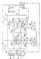
- FIG. 1 is an overall configuration diagram of a hydraulic system according to a first embodiment of the present invention
- FIG. 2 is a diagram illustrating an operation system of the hydraulic system.
- the hydraulic system includes a plurality of variable displacement hydraulic pumps (main pumps) driven by an engine 1 (see FIG. 7), such as first and second hydraulic pumps 2 and 3, A plurality of hydraulic actuators including hydraulic actuators 5 and 6 driven by the pressure oil discharged from the second hydraulic pumps 2 and 3, and pressure oil supplied to the hydraulic actuators 5, 6,.
- Flow rate / direction control valve 13 for controlling the flow (flow rate and direction) of pressure oil supplied from the second hydraulic pump 3 to the hydraulic actuators 5, 6,. , 14 and a control valve device 15 incorporating a plurality of flow rate / direction control valves.
- the flow rate / direction control valves 11 to 14 are of a center bypass type, the flow rate / direction control valves 11, 12 are arranged on the center bypass line 26, and the flow rate / direction control valves 13, 14 are arranged on the center bypass line 27. ing. That is, the center bypass line 26 extends through the flow rate / direction control valves 11, 12,..., And the center bypass line 27 extends through the flow rate / direction control valves 13, 14,.
- the upstream side of the center bypass line 26 is connected to the discharge oil passage 2 a of the first hydraulic pump 2, the downstream side is connected to the tank T, and the upstream side of the center bypass line 27 is connected to the discharge oil passage 3 a of the second hydraulic pump 3.
- the downstream side is connected to the tank T.
- the flow rate / direction control valves 11, 12 are connected in parallel to the discharge oil passage 2 a of the first hydraulic pump 2, and constitute a first hydraulic circuit together with the hydraulic actuators 5, 6.
- the flow rate / direction control valves 13, 14 are connected in parallel to the discharge oil passage 3 a of the second hydraulic pump 3 and constitute a second hydraulic circuit together with the hydraulic actuators 5, 6.
- the hydraulic actuator 5 is a hydraulic cylinder (boom cylinder) that raises and lowers the boom of the excavator
- the hydraulic actuator 6 is a hydraulic cylinder (arm cylinder) that pushes and pulls the arm.
- the flow rate / direction control valves 11 and 13 are both for a boom, and the flow rate / direction control valves 13 and 14 are both for an arm.
- the boom cylinder 5 is connected to the flow / direction control valves 11 and 13 via the first and second actuator lines (hydraulic piping) 31 and 32, and the arm cylinder 6 is similarly connected to the flow / direction control valves 12 and 14. 33 and 34 are connected.
- the boom cylinder 5 has two cylinder chambers (first and second cylinder chambers) 5a and 5b on the bottom side and the rod side, the bottom cylinder chamber 5a is connected to the actuator line 31, and the rod side cylinder chamber 5b is an actuator. Connected to line 32.
- the arm cylinder 6 has two cylinder chambers (first and second cylinder chambers) 6a and 6b on the bottom side and the rod side.
- the bottom cylinder chamber 6a is connected to the actuator line 33, and the rod side cylinder chamber 6b. Is connected to the actuator line 34.
- the boom cylinder 5 is supplied with the discharge oil from the first and second hydraulic pumps 2 and 3 through the flow and direction control valves 11 and 13, and the arm cylinder 6 is supplied with the flow and direction control valves 13 and 13. 14, the oil discharged from the first and second hydraulic pumps 2 and 3 is joined and supplied.
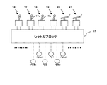
- the hydraulic system in the present embodiment includes a plurality of operation lever devices including operation lever devices 16 and 17 that generate an operation pilot pressure for operating the flow rate / direction control valves 11 to 14. 16 to 19, operating pedal devices 20 and 21, and a shuttle block 23 to which the operating pilot pressure generated by the operating lever devices 16 to 19 and the operating pedal devices 20 and 21 is guided.
- the shuttle block 23 includes a plurality of passages that directly output the operation pilot pressure generated by the operation lever devices 16 to 19 and the operation pedal devices 20 and 21, and the flow rate / direction control valves 11, 12... Related to the first hydraulic pump 2.
- a shuttle valve group that selects the highest operating pilot pressure of the operating pilot pressures to operate and outputs as a first pump control pressure Pp1 for controlling the displacement (displacement volume) of the first hydraulic pump 2; In order to control the capacity (displacement volume) of the second hydraulic pump 3 by selecting the highest operating pilot pressure among the operating pilot pressures for operating the flow rate / direction control valves 13, 14. And a shuttle valve group that outputs the second pump control pressure Pp2.
- the operating lever device 16 is used for a boom, and the operating pilot pressure Ppbu of the boom raising command according to the operating direction of the operating lever 16a based on the discharge pressure of the pilot pump 46 driven by the engine 1 (see FIG. 7) or the boom lowering.
- a pressure reducing valve for generating a command operation pilot pressure Ppbd is provided, and the generated operation pilot pressure Ppbu or Ppbd is guided to a corresponding pressure receiving portion of the flow rate / direction control valves 11, 13, and the flow rate / direction control valve 11. , 13 are switched in the boom raising direction (left direction in the figure) or the boom lowering direction (right direction in the figure) by the operation pilot pressure Ppbu or Ppbd.
- the operating lever device 17 is for an arm, and based on the discharge pressure of the pilot pump 46, the operation of the arm cloud (arm pulling) command according to the operating direction of the operating lever 17a or the operation of the arm pressure (push arm) command
- the pressure reducing valve for generating the pilot pressure Ppad is provided, and the generated operation pilot pressure Ppac or Ppad is guided to a corresponding pressure receiving portion of the flow rate / direction control valves 12, 14, and the flow rate / direction control valves 12, 14 are
- the operation pilot pressure Ppac or Ppad is switched to the arm cloud direction (left direction in the figure) or the arm dump direction (right direction in the figure).
- operation lever devices 16 to 19 and the operation pedal devices 20 and 21 are collectively referred to as an operation device (operation means).
- FIG. 3 (a) is an enlarged view of the symbols of the center bypass type flow rate / direction control valves 11-14
- FIG. 3 (b) is an opening of the center bypass type flow rate / direction control valves 11-14. It is a figure which shows an area characteristic.
- the center bypass type flow rate / direction control valves 11-14 each have a center bypass passage portion Rb, a meter-in passage portion Ri, and a meter-out passage portion Ro, and these passage portions are provided for the flow rate / direction control valves 11-14.
- the center bypass passage portion Rb is located on the center bypass line 26 or 27, and the meter-in passage portion Ri connects the pressure oil supply line 25a connected to the discharge oil passage 2a or 3a of the hydraulic pump 2 or 3 to the actuator line 31 or 32; 33.
- the meter-out passage portion Ro is located on an oil passage that communicates the actuator line 31 or 32; 33 or 34 with the tank T, respectively.
- the pressure oil supply line 25a is provided with a load check valve 25b for preventing the backflow of pressure oil from the hydraulic actuator side.
- the center bypass passage Rb has an opening area characteristic as indicated by A1 in FIG. 3B, and the meter-in passage portion Ri has an opening area characteristic as indicated by A2 in FIG. 3B.
- the horizontal axis in FIG. 3 (b) is the operation pilot pressure generated by the corresponding operation device, and generally corresponds to the operation amount of the operation lever or the operation pedal or the stroke of the flow rate / direction control valve.
- the vertical axis in FIG. 3B is the opening area of the center bypass passage Rb and the meter-in passage Ri.
- the opening area of the center bypass passage portion Rb decreases, The opening area of the meter-in passage portion Ri increases.
- the opening area of the center bypass passage portion Rb becomes zero (fully closed), and the opening area of the meter-in passage portion Ri becomes maximum. That is, the change in the opening area with respect to the operating pilot pressure in the center bypass passage Rb is opposite to the change in the opening area with respect to the operating pilot pressure in the meter-in passage Ri.
- the opening area characteristic of the meter-out passage portion Ro is substantially the same as the opening area characteristic of the meter-in passage portion Ri.
- the first hydraulic pump 2 includes a first regulator 36
- the second hydraulic pump 3 includes a second regulator 37.
- the first regulator 36 inputs the first pump control pressure Pp1 described above and the discharge pressure of the first hydraulic pump 2 related to itself, and performs positive control and input torque limit control.
- the second regulator 37 inputs the second pump control pressure Pp2 described above and the discharge pressure of the second hydraulic pump 3 related to itself, and performs positive control and input torque limit control.
- FIG. 4 is a diagram showing the relationship between pump control pressure and pump displacement in positive control.
- the first regulator 36 controls the displacement of the first hydraulic pump 2 so as to increase as the first pump control pressure Pp1 increases.
- qmin is the minimum displacement volume of the first and second hydraulic pumps 2 and 3
- qmax is the maximum displacement volume of the first and second hydraulic pumps 2 and 3.
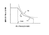
- FIG. 5 is a diagram showing the relationship between pump discharge pressure and maximum pump displacement in input torque limit control.
- the first regulator 36 follows the maximum absorption torque characteristic lines T1 and T2, As the pump discharge pressure increases, the maximum displacement of the first hydraulic pump 2 is decreased, and the displacement of the first hydraulic pump 2 is controlled so that the absorption torque of the first hydraulic pump 2 is maintained at a substantially constant value. To do.
- TE is the pump base torque assigned to the first and second hydraulic pumps 2 and 3 among the output torque of the engine that drives the first and second hydraulic pumps 2 and 3, and the maximum absorption torque characteristic line T1.
- T2 is set to be slightly smaller than the pump base torque TE.
- the first hydraulic pump 36 responds to the operation amount (required flow rate) of the corresponding operation device (operation lever device and operation pedal device).
- the torque limit control characteristic line T1 , T2 to decrease the displacement volume of the first hydraulic pump 2, and the total absorption torque of the first and second hydraulic pumps 2, 3 exceeds the maximum absorption torque set by the torque limit control characteristic lines T1, T2. Control to not. ⁇ Control system> Returning to FIG.
- the hydraulic system according to the present embodiment is further characterized by a center bypass cut valve 41 disposed on the most downstream side of the center bypass line 26 associated with the first hydraulic pump 2, and a boom raising.
- the pressure sensor 42 for detecting the operation pilot pressure Ppbu, the pressure sensor 43 for detecting the pressure (boom bottom pressure) in the bottom cylinder chamber 5a of the boom cylinder 5, the controller 44, and the control signal from the controller 44 are operated.
- an electromagnetic valve 45 that generates a control pressure based on a discharge pressure of a pilot pump 46 driven by the engine 1 (see FIG. 7).
- the control pressure of the electromagnetic valve 45 is applied to the center bypass cut valve 41 to switch the center bypass cut valve 41 from the open position to the closed position.
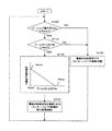
- FIG. 6 is a flowchart showing the processing contents of the controller 44.
- the controller 44 inputs the detection signal of the pressure sensor 42, and determines whether or not the boom raising operation pilot pressure Ppbu is larger than a predetermined value Ppmin (step S100).
- the predetermined value Ppmin is the minimum operation pilot pressure generated when the operation lever or the operation pedal of the operation device (operation lever device and operation pedal device) is operated, and the operation pilot pressure Ppbu for raising the boom is the minimum operation. That it is larger than the pilot pressure Ppmin means that the operation lever 16a of the boom operation lever device 16 is operated in the boom raising direction.
- the predetermined value Ppmin is, for example, about 0.5 MPa.
- the controller 44 When the boom raising operation pilot pressure Ppbu is larger than the predetermined value Ppmin, the controller 44 further inputs a detection signal of the pressure sensor 43 so that the pressure (boom bottom pressure) Pbb in the bottom cylinder chamber 5a of the boom cylinder 5 is increased. It is determined whether it is larger than a predetermined value Pbb0 (step S110).
- the predetermined value Pbb0 is the minimum value of the boom bottom pressure (load holding pressure) that is suitable for application of the present invention at the time of lifting work.
- the fact that the boom bottom pressure Pbb is larger than the predetermined value Pbb0 This means that the present invention is preferably applied to work.
- the predetermined value Pbb0 is, for example, about 25 MPa.
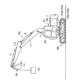
- FIG. 7 is a view showing the appearance of a hydraulic excavator (work machine) on which the hydraulic system of the present invention is mounted.
- the hydraulic excavator includes a lower traveling body 100, an upper swing body 101, and a front work machine 102.
- the lower traveling body 100 has left and right crawler traveling devices 103a and 103b, and is driven by left and right traveling motors 104a and 104b.
- the upper turning body 101 is mounted on the lower traveling body 100 so as to be turnable, and is turned by the turning motor 7.
- the front work machine 102 is attached to the front part of the upper swing body 101 so as to be able to be raised and lowered.
- the upper swing body 101 is provided with an engine room 106 and a cabin (operating room) 107.
- the engine room 106 and hydraulic devices such as the first and second hydraulic pumps 2 and 3 and the pilot pump 46 are arranged in the cabin.
- operating devices such as the operating lever devices 16 to 19 and operating pedal devices 20 and 21 are arranged.
- the front work machine 102 has an articulated structure having a boom 111, an arm 112, and a bucket 113.
- the boom 111 rotates in the vertical direction by expansion and contraction of the boom cylinder 5, and the arm 112 is in the vertical and longitudinal directions by expansion and contraction of the arm cylinder 6.
- the bucket 113 is rotated up and down and back and forth by the expansion and contraction of the bucket cylinder 8.
- a retractable hook 130 is provided on the back of the bucket 113.
- the hook 130 is for hanging work, and as shown in the drawing, a wire is hung on the hook 130 attached to the back of the bucket to lift the hanging load 131.
- the lifting and lowering of the boom 111 (boom raising and lowering) moves (position adjustment) the lifting load 131 in the vertical direction (height direction) and pushes and pulls the arm 112 (arm dump and arm cloud).
- the suspended load 131 is moved (position adjustment) in the front-rear and lateral directions (horizontal direction) by turning.
- the bottom cylinder chamber 5a of the boom cylinder 5 becomes the load holding side, and a high holding pressure is generated in the bottom cylinder chamber 5a.
- the suspended load work is a work requiring a heavy load and a fine speed operation (heavy load fine speed operation work).
- the boom cylinder 5 has the bottom side cylinder chamber 5a and the rod side cylinder chamber 5b, and the bottom side cylinder chamber 5a which is one of the bottom side cylinder chamber and the rod side cylinder chamber at the time of heavy load fine speed operation work.
- a specific hydraulic actuator on the load holding side is configured, and the pressure sensors 42 and 43, the controller 44, and the electromagnetic valve 45 are specified by the operation means 16 corresponding to the specific hydraulic actuator 5 among the plurality of operation means 16 to 21.
- the center bypass cut valve 41 When operated to supply pressure oil to the cylinder chamber 5 a on the load holding side of the hydraulic actuator 5, the center bypass cut valve 41 is operated so that the discharge pressure of the first hydraulic pump 2 is higher than the load pressure of the specific hydraulic actuator 5.
- the control means for controlling so as to be higher is also configured.
- the operation detecting means for detecting whether or not the pressure holding oil is operated to be supplied to the cylinder chamber 5a on the load holding side is configured, and the function of step S120 and the electromagnetic valve 45 shown in FIG. Bypass that activates the center bypass cut valve 41 when it is detected by the operation detection means that the operation means 16 corresponding to the specific hydraulic actuator 5 is operated to supply pressure oil to the cylinder chamber 5a on the load holding side.
- the control means is configured.
- the pressure sensor 42 detects the operation signal of the operation means 16 when the operation means 16 corresponding to the specific hydraulic actuator 5 is operated to supply pressure oil to the cylinder chamber 5a on the load holding side.
- the pressure sensor 43 constitutes second detection means for detecting the pressure in the cylinder chamber 5a on the load holding side of the specific hydraulic actuator 5, and the controller 44 and the electromagnetic valve 45 are the first detection means.
- the operation pilot pressure Ppbu of the boom raising command is detected by the pressure sensor 42, and the detection signal of the pressure sensor 42 is detected by the pressure sensor 43 that detects the pressure (boom bottom pressure) of the bottom cylinder chamber 5 a of the boom cylinder 5.
- the signal is input to the controller 44 together with the signal.
- the controller 44 performs the processing of the flowchart shown in FIG. 6 based on the detection signal.
- the boom operation lever 16a is operated, and the operation pilot pressure Ppbu satisfies Ppbu> Ppmin.
- the boom bottom pressure Pbb is Pbb> Pbb0.
- the discharge pressure on the first hydraulic pump 2 side rises quickly and exceeds the boom bottom pressure Pbb.
- the oil discharged from the first hydraulic pump 2 is supplied to the bottom cylinder chamber 5a (load holding cylinder chamber) of the boom cylinder 5, and the boom cylinder 5 is driven in the extending direction to rotate the boom upward.
- the center bypass passage portion Rb and the meter-in passage portion Ri have an operation pilot pressure (a lever operation amount of the operation lever device).
- the operating pilot pressure the amount of lever operation of the operating lever device
- the opening area of the center bypass passage Rb decreases and the opening area of the meter-in variable throttle Ri increases.
- the discharge pressure of the hydraulic pumps 2 and 3 is inversely proportional to the opening area of the center bypass passage Rb, and the discharge pressure of the hydraulic pumps 2 and 3 decreases as the opening area of the center bypass passage Rb decreases.
- the displacement volume of the hydraulic pumps 2 and 3 controlled by the regulators 36 and 37 increases the amount of lever operation of the operation lever device 16 as shown in FIG.
- the second pump control pressures Pp1, Pp2 increase as they increase. Therefore, when the lever operation amount of the operation lever 16a of the operation lever device 16 increases, the discharge flow rates of the first and second hydraulic pumps 2 and 3 increase, and a corresponding portion of the discharge oil of the first and second hydraulic pumps 2 and 3 Returns to the tank via the center bypass lines 26, 27. As a result, energy loss increases and the fuel consumption of the engine 1 deteriorates.
- the movement of the suspended load in the suspended load operation is not only a high load but also a task that requires a fine speed operation (heavy load fine speed operation work), and therefore the result of greatly operating the operation lever 16a of the operation lever device 16
- the discharge flow rates of the first and second hydraulic pumps 2 and 3 are increased, there is a problem that the operability at a low speed is lowered.
- the operation lever 16a of the operation lever device 16 is slightly operated.
- the center bypass cut valve 41 is activated and the center bypass line 26 is shut off, so that the discharge pressures of the first and second hydraulic pumps 2 and 3 are immediately increased, and the boom cylinder 5 having a high load pressure is easily made. It is possible to drive, thereby reducing energy loss and preventing deterioration of fuel consumption, and obtaining good fine speed operability.
- FIG. 8 is a flowchart showing the processing contents of the controller provided in the hydraulic system in the present embodiment.
- the overall configuration of the hydraulic system in the present embodiment is the same as that shown in FIGS. 1 and 2 of the first embodiment, and the description thereof will be omitted below.
- the controller 44 performs the processes of steps S100, S110, and S130 similar to those in the first embodiment. That is, the detection signal of the pressure sensor 42 is input to determine whether or not the boom raising operation pilot pressure Ppbu is larger than a predetermined value Ppmin (step S100), and the boom raising operation pilot pressure Ppbu is determined to be a predetermined value Ppmin. If it is greater than the pressure, a detection signal from the pressure sensor 43 is further input to determine whether or not the pressure in the bottom cylinder chamber 5a (boom bottom pressure) of the boom cylinder 5 is greater than a predetermined value Pbb0 (step S110).
- the detection signal of the pressure sensor 42 is input to determine whether or not the boom raising operation pilot pressure Ppbu is larger than a predetermined value Ppmin (step S100), and the boom raising operation pilot pressure Ppbu is determined to be a predetermined value Ppmin. If it is greater than the pressure, a detection signal from the pressure sensor 43 is further input to determine whether or not the pressure in the bottom cylinder chamber
- the controller 44 stores the boom bottom pressure detected by the pressure sensor 43 in the memory.
- the opening area A of the center bypass cut valve 41 corresponding to the boom bottom pressure at that time is calculated (step S140).
- the memory table as shown in FIG. 8, when the boom bottom pressure is a predetermined value Pbb0, the opening area A is the maximum Amax (fully open), and the opening area A increases as the boom bottom pressure becomes higher.
- the boom bottom pressure reaches a predetermined value Pbba, the relationship between the boom bottom pressure Ppbu and the opening area A at which the opening area A becomes 0 is set.
- the predetermined value Pbba is about 30 MPa, for example.
- the controller 44 calculates an electromagnetic valve control signal for setting the opening area of the center bypass cut valve 41 to the opening area A calculated in step S140, and after applying a soft filtering process to the control signal, It outputs to the valve 45 (step S150).
- the function of the controller 44 shown in FIG. 8 and the solenoid valve 45 shown in FIG. 1 have the second detection value because the value of the operation signal detected by the first detection means (pressure sensor 42) is larger than the first predetermined value Ppmin.
- the operating means 16 corresponding to the specific hydraulic actuator 5 applies pressure oil to the cylinder chamber 5a on the load holding side of the specific hydraulic actuator 5. It determines with having operated so that it may supply, and constitutes a bypass control means which operates center bypass cut valve 41.
- the bypass control means calculates the target opening area of the center bypass cut valve 41 that decreases as the pressure detected by the second detection means (pressure sensor 43) increases, and the center bypass cut The center bypass cut valve 41 is controlled so that the opening area of the valve 41 becomes the target opening area.
- the opening area A of the center bypass cut valve 41 corresponding to the boom bottom pressure at that time is calculated, and the operation of the center bypass cut valve 41 is controlled so that the opening area can be obtained.
- the opening area of the center bypass cut valve 41 is reduced by a necessary amount in accordance with the load (load) of the suspended load during the suspended load operation, thereby increasing the discharge pressure of the first hydraulic pump 2. It becomes smooth, the boom cylinder 5 is driven smoothly, and a smooth hanging work is possible.
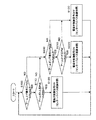
- FIG. 9 is a flowchart showing the processing contents of the controller provided in the hydraulic system in the present embodiment.
- the overall configuration of the hydraulic system in the present embodiment is a diagram of the first embodiment, except that the pressure sensor 43 that detects the boom bottom pressure shown in FIG. 1 of the first embodiment is not provided. 1 and FIG. 2 are the same as those shown in FIG.
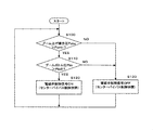
- the controller 44 performs the processes of steps S100 and S130 similar to those in the first embodiment. That is, the detection signal of the pressure sensor 42 is input to determine whether or not the boom raising operation pilot pressure Ppbu is larger than a predetermined value Ppmin (step S100), and the boom raising operation pilot pressure Ppbu is determined to be a predetermined value Ppmin. If not, the control signal for the electromagnetic valve 45 remains OFF (step S130), and the center bypass cut valve 41 is held in the open position.
- Step S160 when the boom raising operation pilot pressure Ppbu is larger than the predetermined value Ppmin, the change rate ⁇ Ppbu of the boom raising operation pilot pressure Ppbu is calculated, and it is determined whether or not this change rate ⁇ Ppbu is smaller than the predetermined value ⁇ Ppbu0.
- the change rate ⁇ Ppbu of the boom raising operation pilot pressure Ppbu corresponds to the operation speed of the operation lever 16a of the boom operation lever device 16, and the predetermined value ⁇ Ppbu0 is a boom operation lever that is assumed when performing a lifting work. This value corresponds to the maximum operation speed of 16a.
- the change rate ⁇ Ppbu of the boom raising operation pilot pressure Ppbu is smaller than the predetermined value ⁇ Ppbu0, which means that the operation lever 16a of the boom operation lever device 16 may be operated in the boom raising direction and is currently being lifted. Means high.
- steps S100 and S160 of the pressure sensor 42 and the controller 44 shown in FIG. 1 shown in FIG. 9 are such that the operation means 16 corresponding to a specific hydraulic actuator among the plurality of operation means 18 to 21 has a heavy load.
- the operation detecting means for detecting whether or not the pressure holding oil is operated to be supplied to the cylinder chamber 5a on the load holding side intended for the slow speed operation work is configured, and the function of step S120 shown in FIG.
- a bypass control means for operating the bypass cut valve 41 is configured.
- the pressure sensor 42 detects the operation signal of the operation means 16 when the operation means 16 corresponding to the specific hydraulic actuator 5 is operated to supply pressure oil to the cylinder chamber 5a on the load holding side.
- the function of the controller 44 shown in FIG. 9 and the electromagnetic valve 45 shown in FIG. 1 calculate the change rate ⁇ Ppbu of the operation signal detected by the first detection means (pressure sensor 42), and When the value is larger than the first predetermined value Ppmin and the rate of change is smaller than the third predetermined value ⁇ Ppbu0, the operating means 16 corresponding to the specific hydraulic actuator 5 enters the cylinder chamber 5a on the load holding side of the specific hydraulic actuator 5. It is determined that the operation is performed so as to supply the pressure oil, and a bypass control unit that operates the center bypass cut valve 41 is configured.
- the rate of change ⁇ Ppbu of the boom raising operation pilot pressure Ppbu is smaller than a predetermined value ⁇ Ppbu0 corresponding to the maximum operation speed of the boom operation lever 16a assumed when carrying a suspended work. Since it is determined that the suspended load work has started, when the suspended load 131 is lifted by raising the boom from a state where the suspended load 131 is placed on the ground, the center bypass cut valve 41 is activated from the time when the lifting of the suspended load 131 is started. To do. As a result, when the suspended load 131 is separated from the ground and a high holding pressure is generated in the bottom cylinder chamber 5a of the boom cylinder 5 and the boom bottom pressure is increased, the discharge pressure of the first hydraulic pump 2 is increased.
- the pressure rises to a pressure higher than the pressure in the bottom cylinder chamber 5a of the boom cylinder 5 (boom bottom pressure), and the discharged oil from the first hydraulic pump 2 is supplied to the bottom cylinder chamber 5a of the boom cylinder 5 and suspended smoothly.
- the load 131 can be lifted from the ground to the air.
- FIG. 10 is an overall configuration diagram of the hydraulic system according to the present embodiment. As a characteristic configuration of the hydraulic system according to the present embodiment, in addition to the configuration shown in FIG.
- FIG. 11 is a flowchart showing the processing contents of the controller 44A.
- the controller 44A performs the processes of steps S100, S110, and S120 similar to those in the first embodiment. That is, when the detection signals of the pressure sensors 42 and 43 are inputted and the boom raising operation pilot pressure Ppbu is larger than the predetermined value Ppmin and the boom bottom pressure is larger than the predetermined value Pbb0, the suspended load caused by the boom raising.
- An ON control signal for exciting the electromagnetic valve 45 is generated based on the determination that the work has started, and the control signal (ON signal) is subjected to a soft filter process and then output to the electromagnetic valve 45.
- the electromagnetic valve 45 generates a control pressure corresponding to the control signal (ON signal), and switches the center bypass cut valve 41 from the open position to the closed position.
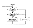
- the controller 44A inputs the detection signal of the pressure sensor 51. Then, it is determined whether or not the operation pilot pressure Ppad of the arm dump (arm push) command is larger than a predetermined value Ppmin (step S200).
- the predetermined value Ppmin is the minimum operation pilot pressure generated when the operation lever or the operation pedal of the operation device (operation lever device and operation pedal device) is operated, and arm dump (arm push)
- the command operation pilot pressure Ppad being larger than the predetermined value Ppmin means that the operation lever 17a of the arm operation lever device 17 is operated in the arm dump direction.
- the controller 44A When the operation pilot pressure Ppad of the arm dump (push arm) command is larger than the predetermined value Ppmin, the controller 44A further inputs a detection signal of the pressure sensor 53, and the pressure (arm arm) of the rod side cylinder chamber 6b of the arm cylinder 6 It is determined whether or not (rod pressure) Par is greater than a predetermined value Par0 (step S210).
- the predetermined value Par0 is the minimum value of the arm rod pressure (load holding pressure) that is suitable for application of the present invention at the time of hanging work, and that the arm rod pressure is larger than the predetermined value Par0 This means that the present invention is preferably applied.
- step S220 If the arm rod pressure is greater than the predetermined value Par0, an ON control signal is output to the electromagnetic valve 45 (step S220), and the center bypass cut valve 41 is switched from the open position to the closed position, as in step S120. .
- the boom cylinder 5 and the arm cylinder 6 have the bottom side cylinder chambers 5a and 6a and the rod side cylinder chambers 5b and 6b.
- Constitutes a specific hydraulic actuator on the load holding side, and the pressure sensors 42, 43, 51, 53, the controller 44A and the electromagnetic valve 45 are composed of the specific hydraulic actuator 5 among the plurality of operating means 18 to 21 (FIG. 2).
- 6 is operated to supply the pressure oil to the cylinder chambers 5a, 6b on the load holding side of the specific hydraulic actuators 5, 6, the center bypass cut valve 41 is operated, 1
- a control means for controlling the discharge pressure of the hydraulic pump 2 to be higher than the load pressure of the specific hydraulic actuators 5 and 6 is configured. That.
- steps S100, S110, S200, S210 shown in FIG. 11 of the pressure sensor 42,43,51,53 and the controller 44A are corresponding to a particular hydraulic actuator 5 and 6 of the plurality of operation means 18-21
- the operation means 16 and 17 are configured as operation detection means for detecting whether or not the pressure holding oil is supplied to the cylinder chamber 5a, 6b or 6a on the load holding side with the intention of heavy load fine speed operation work.
- the functions of steps S120 and S220 shown in FIG. 11 and the electromagnetic valve 45 are the same as that of the operation detecting means corresponding to the specific hydraulic actuators 5 and 6 by the operation detecting means.
- Bypass control means for activating the center bypass cut valve 41 when it is detected that the operation has been made to supply Configure the stage.
- the pressure sensors 42 and 51 are the operation means 16 and 17 when the operation means 16 and 17 corresponding to the specific hydraulic actuators 5 and 6 are operated so as to supply pressure oil to the cylinder chambers 5a and 6b on the load holding side. 17 constitutes first detection means for detecting the operation signal, and pressure sensors 43 and 53 constitute second detection means for detecting the pressure in the cylinder chambers 5a, 6b on the load holding side of the specific hydraulic actuators 5, 6.
- the value of the operation signal detected by the first detection means is larger than the first predetermined value Ppmin
- the pressure detected by the second detection means is higher than the second predetermined values Pbb0 and Par0.
- the operation means 16 and 17 corresponding to the specific hydraulic actuators 5 and 6 are operated so as to supply pressure oil to the cylinder chambers 5a and 6b on the load holding side of the specific hydraulic actuators 5 and 6. It determines with having been performed, and the bypass control means which operates the center bypass cut valve 41 is comprised.
- the suspended load 131 is moved back and forth (position adjustment) by pushing and pulling the arm 112 (arm dump and arm cloud).
- the rod side cylinder chamber 6b of the arm cylinder 6 becomes the load holding side when the arm 112 (FIG. 7) is rotated from the vertical position to the front of the vehicle body (in the direction away from the vehicle body).
- a high holding pressure is generated in the rod side cylinder chamber 6b.
- the operator moves the operation lever 17a of the arm operation lever device 17 (FIG. 2) in the arm dump direction with the intention of moving the suspended load 131 forward by arm dump in the hanging work.
- the operation pilot pressure Ppad of the arm dump command is generated, and the flow rate / direction control valves 12 and 14 are moved in the arm cloud direction (right direction in the drawing) as in the case where the operation lever 16a of the boom operation lever device 16 is operated.
- the first and second hydraulic pumps 2 and 3 according to the magnitudes of the first pump control pressure Pp1 and the second pump control pressure Pp2 (the magnitude of the operation pilot pressure Ppbu of the boom raising command).
- the displacement volume increases, and the discharge flow rates of the first and second hydraulic pumps 2 and 3 increase.
- the operation pilot pressure Ppad of the arm dump command is detected by the pressure sensor 51, and the detection signal of the pressure sensor 53 is detected by the pressure sensor 53 that detects the pressure (arm rod pressure) of the rod side cylinder chamber 6b of the arm cylinder 6.
- the operation lever 16a of the boom operation lever device 16 is operated, it is input together with the signal to the controller 44A.
- a signal is output, the center bypass cut valve 41 is switched from the open position to the closed position, and the center bypass line 26 is shut off.
- the discharge pressure on the first hydraulic pump 2 side rises quickly and exceeds the arm rod pressure Par.
- the oil discharged from the first hydraulic pump 2 is supplied to the rod side cylinder chamber 6b (load holding side cylinder chamber) of the arm cylinder 6, and the arm cylinder 6 is driven in the contracting direction to move the arm forward (in the direction away from the vehicle body). ).
- step S210 the determination in step S210 is denied, so the center bypass cut valve 41 does not operate and the arm cylinder 6 operates normally.
- the amount of operation of the arm operation lever 17a can be reduced. Loss can be reduced to prevent fuel consumption from deteriorating and good fine speed operability can be obtained.
Landscapes
- Engineering & Computer Science (AREA)
- General Engineering & Computer Science (AREA)
- Mining & Mineral Resources (AREA)
- Civil Engineering (AREA)
- Structural Engineering (AREA)
- Physics & Mathematics (AREA)
- Fluid Mechanics (AREA)
- Mechanical Engineering (AREA)
- Fluid-Pressure Circuits (AREA)
- Operation Control Of Excavators (AREA)
Abstract
Description
(2)上記(1)において、好ましくは、前記制御手段は、前記複数の操作手段のうち前記特定の油圧アクチュエータに対応する操作手段が前記重負荷微速操作作業を意図して前記負荷保持側のシリンダ室に圧油を供給するよう操作されたかどうかを検出する操作検出手段と、前記操作検出手段によって前記特定の油圧アクチュエータに対応する操作手段が前記負荷保持側のシリンダ室に圧油を供給するよう操作されたことが検出されたときに、前記センターバイパスカット弁を作動させるバイパス制御手段とを備える。
(3)また、上記(1)において、好ましくは、前記制御手段は、前記特定の油圧アクチュエータに対応する操作手段を前記負荷保持側のシリンダ室に圧油を供給するよう操作したときの前記操作手段の操作信号を検出する第1検出手段と、前記特定の油圧アクチュエータの負荷保持側のシリンダ室の圧力を検出する第2検出手段と、前記第1検出手段で検出した操作信号の値が第1所定値より大きく、前記第2検出手段で検出した圧力が第2所定値より高いときに、前記特定の油圧アクチュエータに対応する操作手段が前記特定の油圧アクチュエータの負荷保持側のシリンダ室に圧油を供給するよう操作されたと判定し、前記センターバイパスカット弁を作動させるバイパス制御手段とを備える。
(4)上記(3)において、前記バイパス制御手段は、前記第2検出手段で検出した圧力が上昇するにしたがって小さくなる前記センターバイパスカット弁の目標開口面積を計算し、前記センターバイパスカット弁の開口面積が前記目標開口面積となるよう前記センターバイパスカット弁を制御することが好ましい。
(5)上記(1)において、前記制御手段は、前記特定の油圧アクチュエータに対応する操作手段を前記負荷保持側のシリンダ室に圧油を供給するよう操作したときの前記操作手段の操作信号を検出する第1検出手段と、前記第1検出手段で検出した操作信号の変化率を計算し、前記操作信号の値が第1所定値より大きく、前記変化率が第3所定値より小さいときに、前記特定の油圧アクチュエータに対応する操作手段が前記特定の油圧アクチュエータの負荷保持側のシリンダ室に圧油を供給するよう操作されたと判定し、前記センターバイパスカット弁を作動させるバイパス制御手段とを備えるものとしてもよい。
<全体構成>
図1は、本発明の第1の実施の形態による油圧システムの全体構成図であり、図2は、油圧システムの操作系を示す図である。
<制御系>
図1に戻り、本実施の形態の油圧システムは、その特徴的構成として、更に、第1油圧ポンプ2に係わるセンターバイパスライン26の最下流側に配置されたセンターバイパスカット弁41と、ブーム上げの操作パイロット圧力Ppbuを検出する圧力センサ42と、ブームシリンダ5のボトム側シリンダ室5aの圧力(ブームボトム圧)を検出する圧力センサ43と、コントローラ44と、コントローラ44からの制御信号により動作し、エンジン1(図7参照)により駆動されるパイロットポンプ46の吐出圧力に基づいて制御圧力を生成する電磁弁45とを備えている。電磁弁45の制御圧力はセンターバイパスカット弁41に印加され、センターバイパスカット弁41を開位置から閉位置に切り換える。
<コントローラ>
図6はコントローラ44の処理内容を示すフローチャートである。
<油圧ショベルと吊り荷作業>
図7は本発明の油圧システムが搭載される油圧ショベル(作業機械)の外観を示す図である。
<請求項との対応>
以上において、ブームシリンダ5は、ボトム側シリンダ室5a及びロッド側シリンダ室5bを有し、重負荷微速操作作業時に、ボトム側シリンダ室及びロッド側シリンダ室のいずれかであるボトム側シリンダ室5aが負荷保持側となる特定の油圧アクチュエータを構成し、圧力センサ42,43、コントローラ44及び電磁弁45は、複数の操作手段16~21のうち特定の油圧アクチュエータ5に対応する操作手段16が特定の油圧アクチュエータ5の負荷保持側のシリンダ室5aに圧油を供給するよう操作されたときにセンターバイパスカット弁41を作動させ、第1油圧ポンプ2の吐出圧力が特定の油圧アクチュエータ5の負荷圧よりも高くなるように制御する制御手段を構成する。
<動作>
吊り荷作業として、図7に示すように、吊り荷131を空中に保持した状態でブーム上により吊り荷131の上方への移動を行う場合を考える。
<効果>
センターバイパス型の流量・方向制御弁11,13にあっては、図3に示したように、センターバイパス通路部Rbとメータイン通路部Riとは操作パイロット圧(操作レバー装置のレバー操作量)に対して逆の開口面積特性を有し、操作パイロット圧(操作レバー装置のレバー操作量)が増大するにしたがってセンターバイパス通路部Rbの開口面積は減少し、メータイン可変絞りRiの開口面積は増大する。一方、油圧ポンプ2,3の吐出圧力はセンターバイパス通路部Rbの開口面積に対して反比例の関係にあり、センターバイパス通路部Rbの開口面積が減少するにしたがって油圧ポンプ2,3の吐出圧力は上昇する。
本発明の第2の実施の形態を図8を用いて説明する。図8は、本実施の形態における油圧システムに備えられるコントローラの処理内容を示すフローチャートである。本実施の形態における油圧システムの全体構成は第1の実施の形態の図1、図2等に示すのと同じであり、以下において説明は省略する。
本発明の第3の実施の形態を図9を用いて説明する。図9は、本実施の形態における油圧システムに備えられるコントローラの処理内容を示すフローチャートである。本実施の形態における油圧システムの全体構成は、第1の実施の形態の図1にあったブームボトム圧を検出する圧力センサ43を備えていない点を除いて、第1の実施の形態の図1、図2等に示すのと同じであり、以下において説明は省略する。
本発明の第4の実施の形態を図10及び図11を用いて説明する。本実施の形態は、吊り荷作業でブーム上げにより吊り荷の上方移動を行う場合だけでなく、アームダンプ(アーム押し)により吊り荷の車体前方(車体から離れる方向)への移動を行う場合にも、本発明の効果が得られるようにしたものである。
<全体構成>
図10は、本実施の形態による油圧システムの全体構成図である。本実施の形態に係わる油圧システムは、その特徴的構成として、第1の実施の形態における図1に示す構成に加え、アームダンプ(アーム押し)指令の操作パイロット圧力Ppadを検出する圧力センサ51と、アームシリンダ6のロッド側シリンダ室6bの圧力(アームロッド圧)Parを検出する圧力センサ53とを備え、コントローラ44Aはこれら圧力センサの検出信号も入力する。
<コントローラ>
図11はコントローラ44Aの処理内容を示すフローチャートである。
以上の実施の形態は本発明の精神の範囲内で種々の変更が可能である。例えば、上記実施の形態では、作業機械が油圧ショベルである場合について説明したが、吊り荷作業等の重負荷微速操作作業を行うことができる作業機械である油圧クレーン、ホイール式ショベル等にも同様に本発明を適用し、同様の効果を得ることができる。また、上記第4の実施の形態では、第1の実施の形態に基づいて、アームダンプ(アーム押し)により吊り荷の車体前方への移動を行う場合にもセンターバイパスカット弁41を作動させるように構成したが、第2又は第3の実施の形態に基づいて、アームダンプ(アーム押し)により吊り荷の車体前方への移動を行う場合にもセンターバイパスカット弁41を作動させるように構成してもよく、この場合は、第4の実施の形態の効果に加え第2又は第3の実施の形態の効果をも得ることができる。
2 第1油圧ポンプ
3 第2油圧ポンプ
5 油圧アクチュエータ(ブームシリンダ)
5a ボトム側シリンダ室
5b ロッド側シリンダ室
6 油圧アクチュエータ(アームシリンダ)
6a ボトム側シリンダ室
6b ロッド側シリンダ室
7 旋回モータ(図6)
8 バケットシリンダ(図6)
11 ブーム用流量・方向制御弁
12 アーム用流量・方向制御弁
13 ブーム用流量・方向制御弁
14 アーム用流量・方向制御弁
16 ブーム用操作レバー装置
17 アーム用操作レバー装置
18~21 その他の操作装置(操作レバー装置及び操作ペダル装置)
23 シャトルブロック
26,27 センターバイパスライン
36 第1レギュレータ
37 第2レギュレータ
41 センターバイパスカット弁
42 圧力センサ
43 圧力センサ
44 コントローラ
44A コントローラ(図9)
45 電磁弁
46 パイロットポンプ
51 圧力センサ
53 圧力センサ
100 下部走行体
101 上部旋回体
102 フロント作業機
103a,103b クローラ式走行装置
104a,104b 走行モータ
106 エンジンルーム
107 キャビン(運転室)
111 ブーム
112 アーム
113 バケット
130 フック
131 吊り荷
Rb センターバイパス通路部
Ri メータイン通路部
Ro メータアウト通路部
Claims (5)
- 油圧ポンプ(2,3)と、
この油圧ポンプの吐出油により駆動される複数の油圧アクチュエータ(5~8,104a,104b)と、
前記油圧ポンプから前記複数の油圧アクチュエータに供給される圧油の流れを制御するセンターバイパス型の複数の流量・方向制御弁(11~14)と、
前記複数の油圧アクチュエータに対応して設けられ、前記複数の流量・方向制御弁をそれぞれ操作する複数の操作手段(16~21)と、
前記複数の操作手段の操作に応じて前記油圧ポンプの吐出量が変化するように前記油圧ポンプの容量を制御するポンプレギュレータ(36,37)とを備え、
前記複数の油圧アクチュエータは、ボトム側シリンダ室(5a;5a,6a)及びロッド側シリンダ室(5b;5b,6b)を有し、重負荷微速操作作業時に、前記ボトム側シリンダ室及びロッド側シリンダ室のいずれかが負荷保持側となる特定の油圧アクチュエータ(5;5,6)を含む作業機械の油圧システムにおいて、
前記センターバイパス型の複数の流量・方向制御弁(11,12)を貫通するセンターバイパスライン(26)の前記特定の油圧アクチュエータ(5;5,6)に対応する流量・方向制御弁(11;11,12)の下流側の位置に配置されたセンターバイパスカット弁(41)と、
前記複数の操作手段(16~21)のうち前記特定の油圧アクチュエータに対応する操作手段(16;16,17)が前記特定の油圧アクチュエータの負荷保持側のシリンダ室(5a;5a,6b)に圧油を供給するよう操作されたときに前記センターバイパスカット弁(41)を作動させ、前記油圧ポンプ(2)の吐出圧力が前記特定の油圧アクチュエータの負荷圧よりも高くなるように制御する制御手段(42~45;42,43,44A,45,51,53)とを備えることを特徴とする作業機械の油圧システム。 - 請求項1記載の作業機械の油圧システムにおいて、
前記制御手段は、
前記複数の操作手段(16~21)のうち前記特定の油圧アクチュエータ(5;5,6)に対応する操作手段(16;16,17)が前記重負荷微速操作作業を意図して前記負荷保持側のシリンダ室(5a;5a,6b)に圧油を供給するよう操作されたかどうかを検出する操作検出手段(42,43,44;42,43,44A,51,53)と、
前記操作検出手段によって前記特定の油圧アクチュエータに対応する操作手段が前記負荷保持側のシリンダ室に圧油を供給するよう操作されたことが検出されたときに、前記センターバイパスカット弁(41)を作動させるバイパス制御手段(44,45;44A,45)とを備えることを特徴とする作業機械の油圧システム。 - 請求項1記載の作業機械の油圧システムにおいて、
前記制御手段は、
前記特定の油圧アクチュエータ(5;5,6)に対応する操作手段(16;16,17)を前記負荷保持側のシリンダ室(5a;5a,6b)に圧油を供給するよう操作したときの前記操作手段の操作信号を検出する第1検出手段(42;42,51)と、
前記特定の油圧アクチュエータの負荷保持側のシリンダ室の圧力を検出する第2検出手段(43;43,53)と、
前記第1検出手段で検出した操作信号の値が第1所定値(Ppmin)より大きく、前記第2検出手段で検出した圧力が第2所定値(Pbb0;Pbb0,Par0)より高いときに、前記特定の油圧アクチュエータに対応する操作手段が前記特定の油圧アクチュエータの負荷保持側のシリンダ室に圧油を供給するよう操作されたと判定し、前記センターバイパスカット弁(41)を作動させるバイパス制御手段(44,45;44A,45)とを備えることを特徴とする作業機械の油圧システム。 - 請求項3記載の作業機械の油圧システムにおいて、
前記バイパス制御手段(44,45)は、前記第2検出手段(43)で検出した圧力が上昇するにしたがって小さくなる前記センターバイパスカット弁(41)の目標開口面積(A)を計算し、前記センターバイパスカット弁の開口面積が前記目標開口面積となるよう前記センターバイパスカット弁を制御することを特徴とする作業機械の油圧システム。 - 請求項1記載の作業機械の油圧システムにおいて、
前記制御手段は、
前記特定の油圧アクチュエータ(5)に対応する操作手段(16)を前記負荷保持側のシリンダ室(5a)に圧油を供給するよう操作したときの前記操作手段の操作信号を検出する第1検出手段(42)と、
前記第1検出手段で検出した操作信号の変化率を計算し、前記操作信号の値が第1所定値(Ppmin)より大きく、前記変化率が第3所定値(ΔPpbu0)より小さいときに、前記特定の油圧アクチュエータに対応する操作手段が前記特定の油圧アクチュエータの負荷保持側のシリンダ室に圧油を供給するよう操作されたと判定し、前記センターバイパスカット弁(41)を作動させるバイパス制御手段(44,45)とを備えることを特徴とする作業機械の油圧システム。
Priority Applications (5)
| Application Number | Priority Date | Filing Date | Title |
|---|---|---|---|
| CN201080045969.0A CN102575690B (zh) | 2009-10-15 | 2010-10-14 | 工程机械的液压系统 |
| US13/501,925 US9051712B2 (en) | 2009-10-15 | 2010-10-14 | Hydraulic system for working machine |
| KR1020127008734A KR101793993B1 (ko) | 2009-10-15 | 2010-10-14 | 작업 기계의 유압 시스템 |
| IN3183DEN2012 IN2012DN03183A (ja) | 2009-10-15 | 2010-10-14 | |
| EP10823452.7A EP2489883A4 (en) | 2009-10-15 | 2010-10-14 | Hydraulic system for operating machine |
Applications Claiming Priority (2)
| Application Number | Priority Date | Filing Date | Title |
|---|---|---|---|
| JP2009238664A JP5388787B2 (ja) | 2009-10-15 | 2009-10-15 | 作業機械の油圧システム |
| JP2009-238664 | 2009-10-15 |
Publications (1)
| Publication Number | Publication Date |
|---|---|
| WO2011046184A1 true WO2011046184A1 (ja) | 2011-04-21 |
Family
ID=43876233
Family Applications (1)
| Application Number | Title | Priority Date | Filing Date |
|---|---|---|---|
| PCT/JP2010/068082 WO2011046184A1 (ja) | 2009-10-15 | 2010-10-14 | 作業機械の油圧システム |
Country Status (7)
| Country | Link |
|---|---|
| US (1) | US9051712B2 (ja) |
| EP (1) | EP2489883A4 (ja) |
| JP (1) | JP5388787B2 (ja) |
| KR (1) | KR101793993B1 (ja) |
| CN (1) | CN102575690B (ja) |
| IN (1) | IN2012DN03183A (ja) |
| WO (1) | WO2011046184A1 (ja) |
Cited By (1)
| Publication number | Priority date | Publication date | Assignee | Title |
|---|---|---|---|---|
| CN103748365A (zh) * | 2011-08-24 | 2014-04-23 | 株式会社小松制作所 | 液压驱动系统 |
Families Citing this family (44)
| Publication number | Priority date | Publication date | Assignee | Title |
|---|---|---|---|---|
| US8899034B2 (en) * | 2011-12-22 | 2014-12-02 | Husco International, Inc. | Hydraulic system with fluid flow summation control of a variable displacement pump and priority allocation of fluid flow |
| KR101861856B1 (ko) | 2012-01-27 | 2018-05-28 | 두산인프라코어 주식회사 | 건설기계의 스윙 모터 유압제어장치 |
| JP5758348B2 (ja) * | 2012-06-15 | 2015-08-05 | 住友建機株式会社 | 建設機械の油圧回路 |
| JP5778086B2 (ja) * | 2012-06-15 | 2015-09-16 | 住友建機株式会社 | 建設機械の油圧回路及びその制御装置 |
| US20140060018A1 (en) * | 2012-08-30 | 2014-03-06 | Pengfei Ma | Hydraulic control system |
| EP2910795B1 (en) * | 2012-10-18 | 2019-06-26 | Hitachi Construction Machinery Co., Ltd. | Work machine |
| KR101729585B1 (ko) * | 2012-12-14 | 2017-04-24 | 볼보 컨스트럭션 이큅먼트 에이비 | 건설기계용 유압회로 |
| WO2014123253A1 (en) * | 2013-02-06 | 2014-08-14 | Volvo Construction Equipment Ab | Swing control system for construction machines |
| KR101763284B1 (ko) * | 2013-07-24 | 2017-07-31 | 볼보 컨스트럭션 이큅먼트 에이비 | 건설기계용 유압회로 |
| CN103527541A (zh) * | 2013-09-16 | 2014-01-22 | 洛阳中重自动化工程有限责任公司 | 一种实现备用泵自动切换的液压控制系统 |
| JP6013389B2 (ja) | 2014-03-24 | 2016-10-25 | 日立建機株式会社 | 作業機械の油圧システム |
| KR102128630B1 (ko) * | 2014-03-24 | 2020-06-30 | 두산인프라코어 주식회사 | 유압시스템에서 스윙 모터의 제어방법 및 유압시스템 |
| JP5823060B2 (ja) * | 2014-09-05 | 2015-11-25 | 株式会社小松製作所 | 油圧ショベル |
| WO2016054047A2 (en) * | 2014-09-29 | 2016-04-07 | Parker-Hannifin Corporation | Directional control valve |
| US9765499B2 (en) | 2014-10-22 | 2017-09-19 | Caterpillar Inc. | Boom assist management feature |
| JP6226851B2 (ja) | 2014-11-06 | 2017-11-08 | 日立建機株式会社 | 作業機械の油圧制御装置 |
| CN104500470B (zh) * | 2014-12-04 | 2017-09-29 | 徐州徐工挖掘机械有限公司 | 一种具有一阀两用的液压系统 |
| EP3290595B1 (en) * | 2015-04-29 | 2021-02-17 | Volvo Construction Equipment AB | Flow rate control apparatus of construction equipment and control method therefor |
| JP6324347B2 (ja) * | 2015-06-01 | 2018-05-16 | 日立建機株式会社 | 建設機械の油圧制御装置 |
| WO2016208780A1 (ko) * | 2015-06-22 | 2016-12-29 | 볼보 컨스트럭션 이큅먼트 에이비 | 건설기계용 유압회로 |
| US10267019B2 (en) | 2015-11-20 | 2019-04-23 | Caterpillar Inc. | Divided pump implement valve and system |
| CN105545851B (zh) * | 2015-12-21 | 2017-07-07 | 中国航空工业集团公司金城南京机电液压工程研究中心 | 一种适用于水上飞机的水舵操纵油路结构 |
| JP6304273B2 (ja) * | 2016-02-05 | 2018-04-04 | コベルコ建機株式会社 | 作業機械の油圧駆動装置 |
| WO2018061165A1 (ja) * | 2016-09-29 | 2018-04-05 | 日立建機株式会社 | 油圧駆動装置 |
| JP6378734B2 (ja) | 2016-10-27 | 2018-08-22 | 川崎重工業株式会社 | 油圧ショベル駆動システム |
| WO2018164465A1 (ko) * | 2017-03-06 | 2018-09-13 | 두산인프라코어 주식회사 | 건설기계의 제어 시스템 및 건설기계의 제어 방법 |
| JP6580618B2 (ja) * | 2017-03-21 | 2019-09-25 | 日立建機株式会社 | 建設機械 |
| JP6698573B2 (ja) * | 2017-03-27 | 2020-05-27 | 日立建機株式会社 | 油圧駆動装置 |
| JP6646007B2 (ja) * | 2017-03-31 | 2020-02-14 | 日立建機株式会社 | 建設機械の油圧制御装置 |
| CN107725507A (zh) * | 2017-11-22 | 2018-02-23 | 江苏恒立液压科技有限公司 | 液压控制系统的控制方法 |
| JP6924161B2 (ja) * | 2018-02-28 | 2021-08-25 | 川崎重工業株式会社 | 建設機械の油圧システム |
| KR102228436B1 (ko) * | 2018-03-15 | 2021-03-16 | 히다찌 겐끼 가부시키가이샤 | 건설 기계 |
| KR102171498B1 (ko) * | 2018-03-19 | 2020-10-29 | 히다찌 겐끼 가부시키가이샤 | 건설 기계 |
| JP7131138B2 (ja) * | 2018-07-04 | 2022-09-06 | コベルコ建機株式会社 | 作業機械の油圧駆動装置 |
| JP7305968B2 (ja) * | 2019-01-28 | 2023-07-11 | コベルコ建機株式会社 | 作業機械における油圧シリンダの駆動装置 |
| JP7461928B2 (ja) * | 2019-03-11 | 2024-04-04 | 住友建機株式会社 | ショベル及びショベルの制御方法 |
| JP7221101B2 (ja) * | 2019-03-20 | 2023-02-13 | 日立建機株式会社 | 油圧ショベル |
| JP7269411B2 (ja) * | 2019-03-27 | 2023-05-08 | 日立建機株式会社 | 作業機械 |
| CN111852969B (zh) * | 2019-04-30 | 2022-06-07 | 丹佛斯动力系统(浙江)有限公司 | 液压系统 |
| JP7268504B2 (ja) * | 2019-06-28 | 2023-05-08 | コベルコ建機株式会社 | 油圧制御装置 |
| CN110388342B (zh) * | 2019-07-22 | 2020-09-04 | 深圳东风汽车有限公司 | 一种用于液压系统减少溢流保护时间的控制方法 |
| CN111733922A (zh) * | 2020-07-06 | 2020-10-02 | 上海三一重机股份有限公司 | 一种挖掘机流量分配系统及挖掘机 |
| JP7053731B2 (ja) * | 2020-07-15 | 2022-04-12 | 日立建機株式会社 | 作業機械 |
| CN115989353A (zh) | 2020-12-24 | 2023-04-18 | 日立建机株式会社 | 作业机械 |
Citations (7)
| Publication number | Priority date | Publication date | Assignee | Title |
|---|---|---|---|---|
| JPS61184102U (ja) * | 1985-05-10 | 1986-11-17 | ||
| JPH1018359A (ja) * | 1996-06-28 | 1998-01-20 | Yutani Heavy Ind Ltd | 建設機械の制御回路 |
| JPH10102547A (ja) * | 1996-09-30 | 1998-04-21 | Yutani Heavy Ind Ltd | 油圧ショベル |
| JPH10103306A (ja) * | 1996-09-30 | 1998-04-21 | Yutani Heavy Ind Ltd | アクチュエータ作動特性制御装置 |
| JP2002295409A (ja) * | 2001-03-30 | 2002-10-09 | Kobelco Contstruction Machinery Ltd | 油圧作業機 |
| JP2005003081A (ja) | 2003-06-11 | 2005-01-06 | Hitachi Constr Mach Co Ltd | 建設機械の油圧制御装置 |
| JP2007145471A (ja) | 2005-11-25 | 2007-06-14 | Hitachi Constr Mach Co Ltd | 建設機械の転倒防止装置 |
Family Cites Families (10)
| Publication number | Priority date | Publication date | Assignee | Title |
|---|---|---|---|---|
| US3814269A (en) * | 1972-05-30 | 1974-06-04 | Caterpillar Tractor Co | Hook for excavator buckets |
| JPH0732603Y2 (ja) * | 1989-07-27 | 1995-07-26 | 東芝機械株式会社 | 油圧ショベルの油圧回路 |
| EP0438604B1 (en) * | 1989-08-16 | 1997-02-05 | Kabushiki Kaisha Komatsu Seisakusho | Hydraulic circuit device |
| US5101628A (en) * | 1990-01-22 | 1992-04-07 | Shin Caterpillar Mitsubishi Ltd. | Energy regenerative circuit in a hydraulic apparatus |
| JPH1136357A (ja) * | 1997-07-23 | 1999-02-09 | Hitachi Constr Mach Co Ltd | 油圧ショベル用クレーン装置 |
| DE19839062C2 (de) * | 1997-08-29 | 2002-04-18 | Komatsu Mfg Co Ltd | Hydraulische Maschinensteuerung |
| JP3874226B2 (ja) * | 1998-04-24 | 2007-01-31 | 株式会社小松製作所 | 油圧駆動機械の制御装置 |
| JP3846775B2 (ja) * | 2001-02-06 | 2006-11-15 | 新キャタピラー三菱株式会社 | 作業機械におけるブームシリンダの油圧制御回路 |
| JP2006183413A (ja) * | 2004-12-28 | 2006-07-13 | Shin Caterpillar Mitsubishi Ltd | 建設機械の制御回路 |
| JP5066987B2 (ja) * | 2007-04-10 | 2012-11-07 | コベルコ建機株式会社 | 油圧ショベルの油圧制御装置 |
-
2009
- 2009-10-15 JP JP2009238664A patent/JP5388787B2/ja not_active Expired - Fee Related
-
2010
- 2010-10-14 WO PCT/JP2010/068082 patent/WO2011046184A1/ja active Application Filing
- 2010-10-14 US US13/501,925 patent/US9051712B2/en not_active Expired - Fee Related
- 2010-10-14 CN CN201080045969.0A patent/CN102575690B/zh active Active
- 2010-10-14 EP EP10823452.7A patent/EP2489883A4/en not_active Withdrawn
- 2010-10-14 IN IN3183DEN2012 patent/IN2012DN03183A/en unknown
- 2010-10-14 KR KR1020127008734A patent/KR101793993B1/ko active IP Right Grant
Patent Citations (7)
| Publication number | Priority date | Publication date | Assignee | Title |
|---|---|---|---|---|
| JPS61184102U (ja) * | 1985-05-10 | 1986-11-17 | ||
| JPH1018359A (ja) * | 1996-06-28 | 1998-01-20 | Yutani Heavy Ind Ltd | 建設機械の制御回路 |
| JPH10102547A (ja) * | 1996-09-30 | 1998-04-21 | Yutani Heavy Ind Ltd | 油圧ショベル |
| JPH10103306A (ja) * | 1996-09-30 | 1998-04-21 | Yutani Heavy Ind Ltd | アクチュエータ作動特性制御装置 |
| JP2002295409A (ja) * | 2001-03-30 | 2002-10-09 | Kobelco Contstruction Machinery Ltd | 油圧作業機 |
| JP2005003081A (ja) | 2003-06-11 | 2005-01-06 | Hitachi Constr Mach Co Ltd | 建設機械の油圧制御装置 |
| JP2007145471A (ja) | 2005-11-25 | 2007-06-14 | Hitachi Constr Mach Co Ltd | 建設機械の転倒防止装置 |
Non-Patent Citations (1)
| Title |
|---|
| See also references of EP2489883A4 |
Cited By (2)
| Publication number | Priority date | Publication date | Assignee | Title |
|---|---|---|---|---|
| CN103748365A (zh) * | 2011-08-24 | 2014-04-23 | 株式会社小松制作所 | 液压驱动系统 |
| US9683585B2 (en) | 2011-08-24 | 2017-06-20 | Komatsu Ltd. | Hydraulic drive system |
Also Published As
| Publication number | Publication date |
|---|---|
| EP2489883A4 (en) | 2017-07-05 |
| KR20120086288A (ko) | 2012-08-02 |
| US20120198831A1 (en) | 2012-08-09 |
| CN102575690B (zh) | 2014-12-17 |
| CN102575690A (zh) | 2012-07-11 |
| JP5388787B2 (ja) | 2014-01-15 |
| JP2011085198A (ja) | 2011-04-28 |
| KR101793993B1 (ko) | 2017-11-06 |
| US9051712B2 (en) | 2015-06-09 |
| IN2012DN03183A (ja) | 2015-09-25 |
| EP2489883A1 (en) | 2012-08-22 |
Similar Documents
| Publication | Publication Date | Title |
|---|---|---|
| JP5388787B2 (ja) | 作業機械の油圧システム | |
| WO2013145528A1 (ja) | 制御装置及びこれを備えた建設機械 | |
| JP2011085198A5 (ja) | ||
| KR101144396B1 (ko) | 굴삭기의 선회복합작업용 유압제어장치 | |
| JP5380240B2 (ja) | 作業機械の油圧駆動装置 | |
| KR102107579B1 (ko) | 건설 기계의 유압 구동 장치 | |
| KR20140034214A (ko) | 작업 기계의 유압 구동 장치 | |
| JP2005083427A (ja) | 建設機械の油圧制御回路 | |
| JP5485007B2 (ja) | 作業車両の油圧制御装置 | |
| JP2010078035A (ja) | 作業機械の油圧シリンダ制御回路 | |
| US20170298590A1 (en) | Hydraulic Drive System for Work Machine | |
| JP2010230039A (ja) | 流体圧回路 | |
| WO2007116896A1 (ja) | 作業機械及び負荷の急速ドロップ方法 | |
| WO2017061220A1 (ja) | 建設機械 | |
| JP7095287B2 (ja) | 旋回式油圧作業機械 | |
| JPH11303814A (ja) | 圧油供給装置 | |
| JPWO2018164238A1 (ja) | ショベル | |
| US11028559B2 (en) | Slewing-type hydraulic work machine | |
| JP6615137B2 (ja) | 建設機械の油圧駆動装置 | |
| JP6591370B2 (ja) | 建設機械の油圧制御装置 | |
| JPWO2019064555A1 (ja) | 作業機械の油圧駆動装置 | |
| JP5357073B2 (ja) | 建設機械のポンプ制御装置 | |
| JP7338292B2 (ja) | 建設機械の油圧制御装置 | |
| JP2008002505A (ja) | 建設機械の省エネ装置 | |
| JP2003090302A (ja) | 建設機械の油圧制御回路 |
Legal Events
| Date | Code | Title | Description |
|---|---|---|---|
| WWE | Wipo information: entry into national phase |
Ref document number: 201080045969.0 Country of ref document: CN |
|
| 121 | Ep: the epo has been informed by wipo that ep was designated in this application |
Ref document number: 10823452 Country of ref document: EP Kind code of ref document: A1 |
|
| DPE1 | Request for preliminary examination filed after expiration of 19th month from priority date (pct application filed from 20040101) | ||
| ENP | Entry into the national phase |
Ref document number: 20127008734 Country of ref document: KR Kind code of ref document: A |
|
| WWE | Wipo information: entry into national phase |
Ref document number: 3183/DELNP/2012 Country of ref document: IN Ref document number: 2010823452 Country of ref document: EP |
|
| WWE | Wipo information: entry into national phase |
Ref document number: 13501925 Country of ref document: US |
|
| NENP | Non-entry into the national phase |
Ref country code: DE |