WO2011045916A1 - Élément d'électrification et dispositif électrophotographique - Google Patents
Élément d'électrification et dispositif électrophotographique Download PDFInfo
- Publication number
- WO2011045916A1 WO2011045916A1 PCT/JP2010/006040 JP2010006040W WO2011045916A1 WO 2011045916 A1 WO2011045916 A1 WO 2011045916A1 JP 2010006040 W JP2010006040 W JP 2010006040W WO 2011045916 A1 WO2011045916 A1 WO 2011045916A1
- Authority
- WO
- WIPO (PCT)
- Prior art keywords
- polymer
- image
- formula
- charging
- charging roller
- Prior art date
Links
- VVBLNCFGVYUYGU-UHFFFAOYSA-N CN(C)c(cc1)ccc1C(c(cc1)ccc1N(C)C)=O Chemical compound CN(C)c(cc1)ccc1C(c(cc1)ccc1N(C)C)=O VVBLNCFGVYUYGU-UHFFFAOYSA-N 0.000 description 1
Images

Classifications
-
- C—CHEMISTRY; METALLURGY
- C08—ORGANIC MACROMOLECULAR COMPOUNDS; THEIR PREPARATION OR CHEMICAL WORKING-UP; COMPOSITIONS BASED THEREON
- C08L—COMPOSITIONS OF MACROMOLECULAR COMPOUNDS
- C08L15/00—Compositions of rubber derivatives
-
- G—PHYSICS
- G03—PHOTOGRAPHY; CINEMATOGRAPHY; ANALOGOUS TECHNIQUES USING WAVES OTHER THAN OPTICAL WAVES; ELECTROGRAPHY; HOLOGRAPHY
- G03G—ELECTROGRAPHY; ELECTROPHOTOGRAPHY; MAGNETOGRAPHY
- G03G15/00—Apparatus for electrographic processes using a charge pattern
- G03G15/02—Apparatus for electrographic processes using a charge pattern for laying down a uniform charge, e.g. for sensitising; Corona discharge devices
- G03G15/0208—Apparatus for electrographic processes using a charge pattern for laying down a uniform charge, e.g. for sensitising; Corona discharge devices by contact, friction or induction, e.g. liquid charging apparatus
- G03G15/0216—Apparatus for electrographic processes using a charge pattern for laying down a uniform charge, e.g. for sensitising; Corona discharge devices by contact, friction or induction, e.g. liquid charging apparatus by bringing a charging member into contact with the member to be charged, e.g. roller, brush chargers
- G03G15/0233—Structure, details of the charging member, e.g. chemical composition, surface properties
-
- C—CHEMISTRY; METALLURGY
- C08—ORGANIC MACROMOLECULAR COMPOUNDS; THEIR PREPARATION OR CHEMICAL WORKING-UP; COMPOSITIONS BASED THEREON
- C08K—Use of inorganic or non-macromolecular organic substances as compounding ingredients
- C08K2201/00—Specific properties of additives
- C08K2201/001—Conductive additives
-
- C—CHEMISTRY; METALLURGY
- C08—ORGANIC MACROMOLECULAR COMPOUNDS; THEIR PREPARATION OR CHEMICAL WORKING-UP; COMPOSITIONS BASED THEREON
- C08K—Use of inorganic or non-macromolecular organic substances as compounding ingredients
- C08K3/00—Use of inorganic substances as compounding ingredients
- C08K3/02—Elements
- C08K3/04—Carbon
Definitions
- the present invention relates to a charging member and an electrophotographic apparatus.
- Patent Document 1 is effective for solving the above problems.
- further technical development is necessary to further suppress the change in electrical resistance associated with the use of the charging member.
- the present inventors examined in order to solve said subject from a material side. As a result, it has been found that using a polybutadiene having a specific terminal modifying group as the binder polymer is extremely effective in solving the above-mentioned problems.
- An object of the present invention is to provide a charging member having uniform electric resistance, which is less likely to change even by continuous current application for a long time, and as a result, the change in charging performance with time is small.
- Another object of the present invention is to provide an electrophotographic apparatus capable of stably forming a high quality electrophotographic image.
- a charging member comprising a conductive support and an elastic layer, the elastic layer comprising a vulcanized rubber,
- the vulcanized rubber is a vulcanized product of a composition containing a binder polymer containing a polymer having a butadiene skeleton and carbon black as conductive particles,
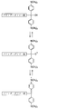
- the polymer having a butadiene skeleton is provided with a charging member in which the molecular end is modified by an atomic group represented by the following general formula (1) or (2):
- X represents OH or SH
- R11 to R15 and R21 to R25 each independently represent a hydrogen atom or a monovalent substituent.
- Y represents OH or SH
- R3 to R5 represent a hydrogen atom or a monovalent substituent.
- an electrophotographic apparatus comprising the above charging member and an electrophotographic photosensitive member disposed in contact with the charging member.
- the present invention it is possible to obtain a charging member in which the electrical resistance is unlikely to change even when the energized state is maintained for a long time, and as a result, the occurrence of unevenness in which the temporal change of the charging performance is better suppressed is less likely to occur. be able to. Further, according to the present invention, it is possible to obtain an electrophotographic apparatus capable of stably providing a high quality electrophotographic image.
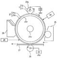
- FIG. 2 is a schematic cross-sectional view showing a configuration of a charging roller.
- FIG. 2 is a view showing a schematic configuration of an electrophotographic apparatus having a charging member. It is a figure which shows schematic structure of the apparatus which measures the electrical resistance of a charging roller. It is explanatory drawing of the production
- FIG. 2 shows a schematic configuration of an electrophotographic apparatus having a charging member.
- the drum-shaped electrophotographic photosensitive member 21 as an object to be charged shown in FIG. 2 has a support 21b having conductivity such as aluminum, a photosensitive layer 21a formed on the support 21b as a basic constituent layer, and an axis 21c. It is rotationally driven at a predetermined circumferential speed in the clockwise direction in FIG. 2 around the center.
- the charging roller 1 is disposed in contact with the electrophotographic photosensitive member 21 and charges (primary charging) the electrophotographic photosensitive member 21 to a predetermined polarity and potential.
- the charging roller 1 comprises a core metal 11 and an elastic layer 12 formed on the core metal 11. Both ends of the core metal 11 are pressed against the electrophotographic photosensitive member 21 by pressing means (not shown). As the photosensitive member 21 is driven to rotate, it is driven to rotate.
- the electrophotographic photosensitive member 21 When a predetermined direct current (DC) bias is applied to the core metal 11 by the rubbing power supply 23a connected to the power supply 23, the electrophotographic photosensitive member 21 is contact-charged to a predetermined polarity and potential.
- the electrophotographic photosensitive member 21 whose peripheral surface has been charged by the charging roller 1 is then subjected to exposure (laser beam scanning exposure, slit exposure of an original image, etc.) of the target image information by the exposure means 24 to obtain the target.
- An electrostatic latent image is formed for the image information of
- the electrostatic latent image is sequentially visualized as a toner image by the developing unit 25.
- the toner image is synchronized with the rotation of the electrophotographic photosensitive member 21 from the sheet feeding unit (not shown) by the transfer unit 26 and the transfer unit between the electrophotographic photosensitive member 21 and the transfer unit 26 with appropriate timing.
- the transfer material 27 is sequentially transferred to the transfer material 27 such as paper transported to the same position.
- the transfer means 26 shown in FIG. 2 is a transfer roller connected to the power supply 22.
- the toner image on the electrophotographic photosensitive member 21 side is transferred to the transfer material 27 by charging the reverse polarity of the toner from the back of the transfer material 27. It will be done.
- the transfer material 27 having the toner image transferred on the surface thereof is separated from the electrophotographic photosensitive member 21 and conveyed to a fixing unit (not shown) to receive the image fixing and output as an image forming material.
- a fixing unit not shown
- the sheet is conveyed to the re-conveying means to the transfer portion.
- the peripheral surface of the electrophotographic photosensitive member 21 after the image transfer is subjected to pre-exposure by the pre-exposure unit 28, and the residual charge on the electrophotographic photosensitive member 21 is removed (dielectricization).
- a known means can be used for this pre-exposure means 28, and for example, an LED chip array, a fuse lamp, a halogen lamp and a fluorescent lamp can be suitably exemplified.
- the peripheral surface of the electrophotographic photosensitive member 21 subjected to static elimination is subjected to removal of attached contaminants such as transfer residual toner by the cleaning means 29 to be cleaned and to be repeatedly subjected to image formation.
- the charging roller 1 may be driven by the electrophotographic photosensitive member 21 which is driven to move by surface movement or may not be rotated, and the charging roller 1 may be non-rotated or predetermined in the forward or reverse direction of the surface moving direction of the electrophotographic photosensitive member 21. You may make it rotationally drive positively with circumferential speed.
- exposure is reading light from reflected light or transmitted light from a document, or a document, scanning a laser beam based on this signal, driving an LED array, or driving a liquid crystal shutter array. And so on.
- Examples of the electrophotographic apparatus which can use the charging member of the present invention include electrophotographic application apparatuses such as copying machines, laser beam printers, LED printers, and electrophotographic plate making systems.
- the charging member of the present invention can also be used as a developing member, a transfer member, a charge removing member, and a conveying member such as a sheet feeding roller, in addition to the charging roller.
- the charging member according to the present invention has a configuration in which a semiconductive elastic layer is stacked on a conductive support.
- FIG. 1 shows a schematic view of a charging roller 1 as an example of the charging member of the present invention.
- the charging roller 1 is composed of a core metal 11 and an elastic layer 12 provided on the outer periphery thereof. If necessary, the surface layer 13 can be provided on the outer side of the elastic layer 12.
- the elastic layer contains a vulcanized rubber.
- the vulcanized rubber is a vulcanized product of a composition including a binder polymer containing a polymer having a butadiene skeleton, and carbon black as conductive particles dispersed in the binder polymer. And the polymer terminal which has butadiene frame
- skeleton is modified
- X represents OH or SH
- R11 to R15 and R21 to R25 each independently represent a hydrogen atom or a monovalent substituent.
- Y represents OH or SH
- R3 to R5 represent a hydrogen atom or a monovalent substituent.
- a polymer whose molecular terminal is modified by an atomic group represented by the following formula (5) or the following formula (6) is suitably used as the polymer having a butadiene skeleton according to the present invention.
- Formula (5) (In formula (5), R51 to R54 each independently represent a hydrogen atom or an alkyl group having 1 to 4 carbon atoms.
- X represents OH or SH
- Formula (6) (In Formula (6), Y represents OH or SH, R 61 represents a hydrogen atom, an alkyl group having 1 to 6 carbon atoms, or a phenyl group, and n represents an integer of 2 to 6).
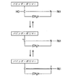
- the resulting cation is presumed to act on functional groups such as quinone, hydroxyl, ester, carboxyl, ether and the like on the surface of carbon black to form a bond between carbon black and the binder polymer. And, due to this bonding, the dispersed state of carbon black in the binder polymer becomes stable.
- Such a phenomenon itself is also described in paragraph “4.1” on page 635 of “The Japan Rubber Association Journal”, Vol. 62, No.
- the carbon black is in a highly dispersed state in the crosslinked rubber, and the crosslinked rubber and the carbon black are chemically bonded it is conceivable that.
- the position of the carbon black in the elastic layer is difficult to move even when the electrified member is maintained in the energized state for a long period of time, and therefore local unevenness in electrical resistance is less likely to occur. It is considered to be a thing.
- Examples of the method for producing a terminal-modified polymer having a butadiene skeleton include the following methods.
- B A method of dissolving a polymer having a butadiene skeleton which has been previously polymerized in a solvent, adding an alkali metal and / or an alkaline earth metal to the dissolved polymer, and adding a modifying treatment agent for reaction.
- the former method is more preferable because the synthesis of the polymer having a butadiene skeleton and its terminal modification can be carried out successively.
- polystyrene obtained by polymerizing 1,3-butadiene monomer, or 1,3-butadiene, isoprene, 1,3-pentadiene, 2,3-dimethyl-1,3-butadiene, 1 And copolymers of 2,3-hexadiene, styrene, ⁇ -methylstyrene, p-methylstyrene, vinyltoluene, vinylnaphthalene and the like.
- Such a polymer has a butadiene skeleton in its main chain, so that sulfur vulcanization is possible, and a charging member having high vulcanization productivity can be obtained.
- Preferred polymers are polybutadiene or styrene-butadiene copolymers.
- terminal modifier for introducing the atomic group of the general formula (1) to the polymer terminal are given below.
- bisaminobenzophenones represented by the following formulas (1-1) to (1-3) are preferably used. This is because a charging member with less change in electrical resistance can be obtained even by long-time energization.
- Formula (1-1) 4,4′-diaminobenzophenone Formula (1-2): 4,4′-bis (dimethylamino) benzophenone
- Formula (1-3) 4,4′-bis (diethylamino) benzophenone
- terminal modifier for introducing the atomic group of the general formula (2) to the polymer terminal are given below.
- Amides or imides eg, formamide, N, N-dimethylformamide, N, N-diethylformamide, acetamide, N, N-dimethylacetamide, N, N-diethylacetamide, aminoacetamide, N, N-dimethyl-N ', N'-Dimethylaminoacetamide, N', N'-Dimethylaminoacetamide, N'-ethylaminoacetamide, N, N-dimethyl-N'-ethylaminoacetamide, N, N-dimethylaminoacetamide, N-phenyl Diacetamide, acrylamide, N, N-dimethyl acrylamide, N, N-dimethyl methacrylamide, propionamide, N, N-dimethyl propionamide, 4-pyridylamide, N, N-dimethyl-4-pyridylamide
- Ureas eg, urea, N, N'-dimethylurea, N, N, N ', N'-tetramethylurea and the like.
- Anilides eg, formanilide, N-methylacetanilide, aminoacetoanilide, benzanilide, p, p'-di (N, N-diethyl) aminobenzanilide, etc.).
- Lactams eg, ⁇ -caprolactam, N-methyl- ⁇ -caprolactam, N-acetyl- ⁇ -caprolactam, 2-pyrrolidone, N-methyl-2-pyrrolidone, N-acetyl-2-pyrrolidone, 2-piperidone, N -Methyl-2-piperidone, 2-quinolone, N-methyl-2-quinolone, 2-indolinone, N-methyl-2-indolinone and the like).
- Isocyanuric acids eg, isocyanuric acid, N, N ', N "-trimethylisocyanuric acid, etc.
- the sulfur-containing compound corresponding to said various compound is mentioned.
- lactams represented by the following formulas (2-1) to (2-9) are particularly preferably used. This is because a charging member with less change in electrical resistance can be obtained even by long-time energization.
- the inventors consider the reason as follows. That is, as shown in FIG. 5, when a binder polymer having a terminal modified group derived from lactam is kneaded with carbon black, a cation is generated in the terminal modified portion.
- lactams listed in the following formulas (2-1) to (2-9) are used as terminal modifiers, a lower alkyl group having 1 to 3 carbon atoms and a phenyl group are bonded to a nitrogen atom Thus, the terminal functional group is more likely to have a cation.
- the composition used for formation of an elastic body layer may be blended and contained other binder polymers other than the above-mentioned terminal-modified polymer.
- binder polymers Natural rubber (NR), isoprene rubber (IR), butadiene rubber (BR), styrene-butadiene (SBR), butyl rubber (IIR), ethylene-propylene-diene terpolymer rubber (EPDM), epichlorohydrin homopolymer (CHC) ), Epichlorohydrin-ethylene oxide copolymer (CHR), epichlorohydrin-ethylene oxide-allyl glycidyl ether terpolymer (CHR-AGE), acrylonitrile-butadiene copolymer (NBR), water of acrylonitrile-butadiene copolymer Additives (H-NBR), chloroprene rubber (CR), acrylic rubber (ACM, ANM) etc.
- NR Natural rubber
- IR isoprene rubber
- BR but
- the composition used to form the elastic layer contains carbon black as conductive particles in order to make the elastic layer conductive.
- the compounding amount of carbon black may be appropriately adjusted so that the electrical resistance of the elastic layer becomes a desired value. Therefore, as a standard of the compounding quantity of carbon black, 30 mass parts or more and 70 mass parts or less are preferred to 100 mass parts of binder polymers. If it is within the range of the above blending amount, it is possible to more surely suppress the fluctuation of the electrical resistance when the charging member is energized for a long period of time. Moreover, it can suppress that the hardness of an elastic-body layer becomes hard too much.
- the type of carbon black is not particularly limited. Specific examples thereof include gas furnace black, oil furnace black, thermal black, lamp black, acetylene black and ketjen black. Functional groups are present on the surface of these carbon blacks, and bonding of the functional groups to molecular terminal functional groups represented by the general formula (1) or (2) makes it possible to combine the binder polymer with the carbon black. A bond is formed.
- the number of surface functional groups of carbon black is indicated by the pH of carbon black measured according to DIN ISO 787/9 and the volatile content of carbon black measured according to DIN 53552. The lower the pH of carbon black and the higher the volatile content, the more surface functional groups on carbon black. If the carbon black has too many surface functional groups, the number of bonding points with the binder polymer on the carbon surface may be too large, resulting in an increase in the electrical resistance of the elastic layer. When the number of surface functional groups of carbon black is too small, the bond between the binder polymer and the carbon black may be weak, and the effect of suppressing current deterioration may be insufficient. Therefore, the pH of carbon black is preferably 3 to 9, and more preferably 5 to 8.
- the volatile content of carbon black is preferably 0.3 to 5.0 wt%, and more preferably 0.5 to 2.0 wt%.
- a filler generally used as a compounding agent for rubber a processing aid, a crosslinking aid, a crosslinking accelerator, a crosslinking accelerator, crosslinking Retarders, softeners, plasticizers, dispersants and the like can be added.
- a mixing method using a closed mixer such as a Banbury mixer or a pressure kneader a mixing method using an open mixer such as an open roll, and the like can be exemplified.
- a composition containing the binder polymer according to the present invention and carbon black as conductive particles is extruded into a tube by an extruder, and this is vulcanized by a vulcanizer to obtain a tube made of vulcanized rubber.
- a core metal is pressed into the tube, and the surface of the tube made of vulcanized rubber is polished to a desired outer diameter.
- a composition containing the binder polymer according to the present invention and carbon black as conductive particles is co-extruded into a cylindrical shape centering on a core metal by an extruder equipped with a crosshead, and the inside of a mold having a desired outer diameter By fixing and heating, an elastic layer made of vulcanized rubber is formed around the core metal.
- the surface of the elastic layer may be subjected to surface modification by irradiating it with ultraviolet rays or electron beams so that dirt such as toner or paper powder is not easily attached to the surface of the elastic layer.
- a surface layer may be further formed on the surface of the elastic layer.
- a terminally modified SBR-2 was obtained in the same manner as the terminally modified SBR-1, except that N-methyl- ⁇ -caprolactam (Formula (4)) was used as a terminal modifier.
- ⁇ Naturated SBR> A non-modified SBR was obtained in the same manner as for the terminally modified SBR-1 except that no terminal modifier was added.
- ⁇ Naturated BR> A non-modified BR was obtained in the same manner as for the terminal-modified BR-1, except that no terminal modifier was added.
- Example 1 (Preparation of Unvulcanized Rubber Composition) The following materials were mixed in a 3-liter pressure kneader at a filling rate of 65 vol% and a blade rotational speed of 30 rpm for 16 minutes to obtain an unvulcanized rubber composition.
- the following materials are mixed with 156 parts of this unvulcanized rubber composition with an open roll with a roll diameter of 12 inches for 20 minutes with a front roll rotation speed of 8 rpm, a rear roll rotation speed of 10 rpm, and a roll gap of 2 mm.
- An unvulcanized rubber composition for an elastic layer was obtained.
- a conductive hot melt adhesive is applied to the axial center portion 232 mm of the cylindrical surface of a cylindrical conductive cored bar (steel, surface plated with nickel) 6 mm in diameter x 252 mm in length, and 30 at 80 ° C. Dried for a minute.
- the rubber tube was pressed into the core metal coated with the adhesive, and secondary vulcanization and adhesion treatment were performed at 160 ° C. for 30 hours in a hot air furnace. Both rubber ends of the obtained composite were cut off to prepare an unpolished roller having a rubber portion length of 232 mm.
- the rubber portion of the unpolished roller is polished with a polishing machine (trade name: LEO-600-F4-BME, manufactured by Mizuguchi Manufacturing Co., Ltd.), and a crown-shaped elastic layer with an end diameter of 8.35 mm and a central diameter of 8.50 mm
- the rubber roller which it has is obtained.
- the surface modification treatment by ultraviolet irradiation was performed on the surface of the obtained rubber roller.
- the surface treatment was performed by irradiating ultraviolet rays with a wavelength of 254 nm so that the integrated light amount would be 8500 mJ / cm 2, and a low-pressure mercury lamp manufactured by Harrison Toshiba Lighting Co., Ltd. was used for the irradiation of ultraviolet rays.
- charge roller A was produced.
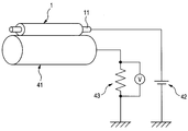
- FIG. 3 shows a schematic configuration of an apparatus for measuring the electrical resistance of the charging roller.
- the charging roller 1 is in pressure contact with a cylindrical aluminum drum 41 having a diameter of 30 mm by pressing means (not shown) at both ends of the core metal 11, and is driven to rotate as the aluminum drum 41 rotates.
- a DC voltage is applied to the metal core portion 11 of the charging roller 1 using the external power supply 42, and the voltage applied to the reference resistor 43 connected in series to the aluminum drum 41 is measured.
- the electrical resistance of the charging roller 1 can be calculated from the measured voltage of the reference resistor 43 by determining the value of the current flowing through the circuit.
- the electrical resistance of the charging roller A is determined by temperature 23 ° C./humidity 50% R.H. H. Under an environment (also described as NN), measurement was performed by applying a voltage of 200 V DC between the core metal and the aluminum drum for 2 seconds using the apparatus of FIG. The rotation speed of the aluminum drum at this time was 30 rpm, and the resistance value of the reference resistance was 100 ⁇ . Data sampling was performed at a frequency of 20 Hz for 1 second after 1 second after voltage application, and the average value of the obtained electrical resistance was taken as the resistance value of the charging roller A. Further, the ratio of the maximum value to the minimum value of the electrical resistance of the charging roller A was calculated as the circumferential unevenness of the electrical resistance of the charging roller A.
- the measurement of the above-mentioned electrical resistance was carried out at a temperature of 15 ° C./humidity 10%. H. Under the environment (also described as LL), temperature 30 ° C./humidity 80% R.H. H. It went under the environment (it describes also as HH). Then, the ratio (LL / HH) of the electrical resistance of the charging roller A under the LL environment and the HH environment was calculated as the environmental dependency of the electrical resistance of the charging roller A.
- the electrification deterioration test of the charging roller A was conducted.
- a voltage of 200 V DC is applied for 2 seconds between the metal core and the aluminum drum in the same manner as the measurement of the electric resistance described above. went.
- the rotation speed of the aluminum drum at this time is 30 rpm, and the resistance value of the reference resistance is 100 ⁇ .
- a voltage of 200 V DC was applied between the core metal and the aluminum drum for 10 minutes to cause the charging roller A to be deteriorated by energization.
- the electrical resistance of the charging roller A after the current-carrying deterioration was measured again in the same manner as the measurement of the initial electrical resistance. Then, a value obtained by dividing the electric resistance of the charging roller A before deterioration by energization by the electric resistance of the charging roller A after deterioration by energization and multiplying by 100 is defined as a resistance retention ratio (%).
- a resistance retention ratio %.
- the hardness of the charging roller A was measured using a microhardness tester MD-1 (trade name, manufactured by Kobunshi Keiki Co., Ltd.) at 23 ° C./55% R.H. H. Measured in peak hold mode in the environment. More specifically, the charge roller A is placed on a metal plate, a metal block is placed, and the charge roller A is easily fixed so that it does not roll, and the center of the charge roller A from the perpendicular direction to the metal plate. Accurately press the measurement terminal and read the value after 5 seconds.
- MD-1 microhardness tester
- An electrophotographic process cartridge (trade name: LBP 5050, Canon Inc.) for incorporating the electrophotographic process cartridge into an electrophotographic process cartridge, incorporating the produced charging roller A (a separate body from the ones for which the resistance measurement and the hardness measurement were performed). Image evaluation).
- the image output is 15 ° C./10% R.S. H. I went under the environment.
- the evaluation image was a halftone image (image in which a line having a width of 1 dot is drawn at an interval of 2 dots in a direction perpendicular to the rotation direction of the electrophotographic photosensitive member) on A4 paper.
- the evaluation of the output image was performed by visually observing the uniformity of the halftone image at the time of single sheet output (initial) and the halftone image outputted after printing (after endurance) with 2500 sheets at a printing density of 1%.
- the charging lateral streaks were ranked A for both the initial image and the image after endurance, and the longitudinal streak evaluation after endurance was also rank A.
- Example 2 An unvulcanized rubber composition was prepared in the same manner as in Example 1 except that the binder polymer was changed to terminal-modified SBR-2. Then, a charging roller B was produced in the same manner as in Example 1 except that the obtained unvulcanized rubber composition was used. About the obtained charging roller B, it carried out similarly to Example 1, and the measurement of hardness and the measurement of hardness of the electrical resistance, the circumferential nonuniformity of resistance, environment dependence, electricity supply deterioration were implemented. As a result, the initial roller resistance value of the charging roller B is 8.0 ⁇ 10 4 ⁇ , the circumferential unevenness is 1.8 times, the environmental dependency is 1.1 times, and the resistance retention ratio due to current deterioration is 77%. Was 72 °. Further, when the image evaluation was performed in the same manner as in Example 1, the charging lateral streaks were rank A for both the initial image and the image after endurance, and the longitudinal streak evaluation after endurance was also rank A.
- Example 3 An unvulcanized rubber composition was prepared in the same manner as in Example 1 except that the binder polymer was changed to terminal-modified BR-1. Then, a charge roller C was produced in the same manner as in Example 1 except that the obtained unvulcanized rubber composition was used. The obtained charging roller C was subjected to the measurement of the electric resistance, the circumferential unevenness of the resistance, the environmental dependency, the deterioration of the conduction and the measurement of the hardness in the same manner as in Example 1. As a result, the initial roller resistance value of the charging roller C is 5.0 ⁇ 10 4 ⁇ , the circumferential unevenness is 1.7 times, the environmental dependency is 1.2 times, and the resistance retention ratio due to current deterioration is 73%. Was 68 °. Further, when the image evaluation was performed in the same manner as in Example 1, the charging lateral streaks were rank A for both the initial image and the image after endurance, and the longitudinal streak evaluation after endurance was also rank A.
- Example 4 Conducting agent except carbon black (trade name: TOKA BLACK # 5500, manufactured by Tokai Carbon Co., Ltd., pH 6.0, volatile content 1.4 wt%), and setting the amount to 28 parts with respect to 100 parts of binder polymer
- an unvulcanized rubber composition was prepared.
- a charging roller D was produced in the same manner as in Example 1 except that the obtained unvulcanized rubber composition was used.
- the measurement of the electric resistance, the circumferential unevenness of the resistance, the environmental dependency, the deterioration of the conduction and the measurement of the hardness were carried out.
- the initial charging roller resistance value of the charging roller D is 1.3 ⁇ 10 5 ⁇
- the circumferential unevenness is 1.9 times
- the environmental dependence is 1.2 times
- the resistance retention ratio due to current deterioration is 55%.
- the image evaluation was carried out in the same manner as in Example 1, the charging lateral streaks were rank A in the initial image, rank B in the durable image, and the longitudinal streak evaluation after durability was rank A.
- Example 5 An unvulcanized rubber composition was prepared in the same manner as in Example 4 except that the compounding amount of carbon black was changed to 30 parts with respect to 100 parts of the binder polymer. Then, a charge roller E was produced in the same manner as in Example 1 except that the obtained unvulcanized rubber composition was used. About the obtained charging roller E, in the same manner as in Example 1, the measurement of the electric resistance, the circumferential unevenness of the resistance, the environmental dependency, the deterioration of the electrification and the measurement of the hardness were performed. As a result, the initial roller resistance value of the charging roller E is 6.7 ⁇ 10 4 ⁇ , the circumferential unevenness is 1.8 times, the environmental dependency is 1.2 times, and the resistance retention ratio due to current deterioration is 60%. Was 66 °. Further, when the image evaluation was performed in the same manner as in Example 1, the charging lateral streaks were rank A for both the initial image and the image after endurance, and the longitudinal streak evaluation after endurance was also rank A.
- Example 6 Conducting agent except that the conductive agent is carbon black (trade name: TOKA BLACK # 7270SB, manufactured by Tokai Carbon, pH 7.5, volatile content 1.0 wt%) and the blending amount is 70 parts with respect to 100 parts of the binder polymer
- an unvulcanized rubber composition was prepared.
- a charging roller F was produced in the same manner as in Example 1 except that the obtained unvulcanized rubber composition was used.
- the measurement of the electric resistance, the circumferential unevenness of the resistance, the environmental dependency, the deterioration of the electrification and the measurement of the hardness were carried out.
- the initial charging roller resistance value of the charging roller F is 2.5 ⁇ 10 4 ⁇
- the circumferential unevenness is 1.4 times
- the environmental dependency is 1.1 times
- the resistance retention ratio due to current deterioration is 78%.
- the image evaluation was performed in the same manner as in Example 1, the charging lateral streaks were rank A for both the initial image and the image after endurance, and the longitudinal streak evaluation after endurance was also rank A.
- Example 7 An unvulcanized rubber composition was prepared in the same manner as in Example 6 except that the blending amount of carbon black was 75 parts with respect to 100 parts of the binder polymer. Then, a charge roller G was produced in the same manner as in Example 1 except that the obtained unvulcanized rubber composition was used. About the obtained charging roller G, in the same manner as in Example 1, the measurement of the electric resistance, the circumferential unevenness of the resistance, the environmental dependency, the deterioration of the conduction and the measurement of the hardness were carried out. As a result, the initial roller resistance value of the charging roller G is 1.7 ⁇ 10 4 ⁇ , the circumferential unevenness is 1.5 times, the environmental dependency is 1.1 times, and the resistance retention ratio due to current deterioration is 79%. Was 85 °. Further, when the image evaluation was performed in the same manner as in Example 1, the charging lateral streaks were rank A for both the initial image and the image after endurance, and the longitudinal streak evaluation after endurance was rank B.
- Example 8 Example 2 except that the conductive agent is carbon black (trade name: TOKA BLACK # 3845, manufactured by Tokai Carbon, pH 10, volatile content 0.4 wt%) and the blending amount is 45 parts with respect to 100 parts of the binder polymer
- An unvulcanized rubber composition was prepared in the same manner as in the above. Then, a charge roller H was produced in the same manner as in Example 1 except that the obtained unvulcanized rubber composition was used. About the obtained charging roller H, in the same manner as in Example 1, the measurement of the electric resistance, the circumferential unevenness of the resistance, the environmental dependency, the deterioration of the electrification and the measurement of the hardness were carried out.
- the initial roller resistance value of the charging roller H is 1.3 ⁇ 10 5 ⁇
- the circumferential unevenness is 1.7 times
- the environmental dependency is 1.2 times
- the resistance retention ratio due to current deterioration is 50%.
- the image evaluation was carried out in the same manner as in Example 1, the charging lateral streaks were rank A in the initial image, rank B in the durable image, and the longitudinal streak evaluation after durability was rank A.
- Example 9 Example 2 except that the conductive agent is carbon black (trade name: Raven 1255, manufactured by Columbillon Carbon, pH 2.5, volatile content 2.7 wt%) and the blending amount is 70 parts with respect to 100 parts of the binder polymer
- An unvulcanized rubber composition was prepared in the same manner as in the above. Then, a charging roller I was produced in the same manner as in Example 1 except that the obtained unvulcanized rubber composition was used. About the obtained charging roller I, in the same manner as in Example 1, the measurement of the electric resistance, the circumferential unevenness of the resistance, the environmental dependency, the deterioration of the electrification and the measurement of the hardness were carried out.
- the initial roller resistance value of the charging roller I is 2.0 ⁇ 10 5 ⁇
- the circumferential unevenness is 1.9 times
- the environmental dependence is 1.1 times
- the resistance retention ratio due to current deterioration is 72%.
- the image evaluation was performed in the same manner as in Example 1, the charging lateral streaks were ranked B for both the initial image and the image after endurance, and the longitudinal streak evaluation after endurance was rank A.
- Comparative Example 1 The binder polymer was unmodified SBR, the conductive agent was carbon black (trade name: TOKA BLACK # 7270SB, manufactured by Tokai Carbon Co., Ltd.), and the compounding amount was 45 parts with respect to 100 parts of binder polymer, Example 1 and In the same manner, an unvulcanized rubber composition was prepared. Then, a charge roller J was produced in the same manner as in Example 1 except that the obtained unvulcanized rubber composition was used. About the obtained charging roller J, in the same manner as in Example 1, the measurement of the electric resistance, the circumferential unevenness of the resistance, the environmental dependency, the deterioration of the conduction and the measurement of the hardness were carried out.
- the initial roller resistance value of the charging roller J is 1.3 ⁇ 10 5 ⁇
- the circumferential unevenness is 2.3 times
- the environmental dependency is 1.2 times
- the resistance retention ratio due to current deterioration is 35%.
- the image evaluation was performed in the same manner as in Example 1, the charging lateral streaks were Rank A in the initial image, Rank D in the post-durability image, and the longitudinal streak evaluation after the durability was Rank A.
- Comparative Example 2 An unvulcanized rubber composition was prepared in the same manner as in Comparative Example 1 except that the binder polymer was changed to unmodified BR. Then, a charging roller K was produced in the same manner as in Example 1 except that the obtained unvulcanized rubber composition was used. About the obtained charging roller K, in the same manner as in Example 1, the measurement of the electric resistance, the circumferential unevenness of the resistance, the environmental dependency, the deterioration of the conduction and the measurement of the hardness were carried out. As a result, the initial roller resistance value of the charging roller K is 8.0 ⁇ 10 4 ⁇ , the circumferential unevenness is 2.5 times, the environmental dependency is 1.2 times, and the resistance retention ratio due to current deterioration is 28%. Was 62 °. Further, when the image evaluation was performed in the same manner as in Example 1, the charging lateral streaks were Rank A in the initial image, Rank C in the post-durability image, and the longitudinal streak evaluation after the durability was Rank A.
Landscapes
- Chemical & Material Sciences (AREA)
- Physics & Mathematics (AREA)
- Health & Medical Sciences (AREA)
- Chemical Kinetics & Catalysis (AREA)
- Medicinal Chemistry (AREA)
- Polymers & Plastics (AREA)
- Organic Chemistry (AREA)
- Engineering & Computer Science (AREA)
- Plasma & Fusion (AREA)
- General Physics & Mathematics (AREA)
- Electrostatic Charge, Transfer And Separation In Electrography (AREA)
Abstract
L'invention porte sur un élément d'électrification, qui a une résistivité électrique homogène, qui subit rarement un changement de résistivité électrique même lorsqu'un courant électrique est appliqué de façon continue pendant une longue période, et qui, par conséquent, subit rarement un changement de performances d'électrification au cours du temps. L'élément d'électrification comprend un support électriquement conducteur et une couche élastique. L'élément d'électrification est caractérisé en ce que la couche élastique comprend un caoutchouc vulcanisé, en ce que le caoutchouc vulcanisé est un produit vulcanisé d'une composition qui comprend un polymère de liant comprenant un polymère ayant un squelette de butadiène et des particules électriquement conductrices comprenant du noir de carbone, et en ce que le polymère ayant un squelette de butadiène comporte une terminaison de molécule modifiée avec un groupe d'atomes ayant une structure spécifique.
Priority Applications (3)
| Application Number | Priority Date | Filing Date | Title |
|---|---|---|---|
| CN201080044921.8A CN102549506B (zh) | 2009-10-15 | 2010-10-08 | 充电构件和电子照相设备 |
| EP10823184.6A EP2490077B1 (fr) | 2009-10-15 | 2010-10-08 | Élément d'électrification et dispositif électrophotographique |
| US13/028,129 US8750762B2 (en) | 2009-10-15 | 2011-02-15 | Charging member with vulcanized rubber, and electrophotographic apparatus including the charging member |
Applications Claiming Priority (2)
| Application Number | Priority Date | Filing Date | Title |
|---|---|---|---|
| JP2009-238094 | 2009-10-15 | ||
| JP2009238094 | 2009-10-15 |
Related Child Applications (1)
| Application Number | Title | Priority Date | Filing Date |
|---|---|---|---|
| US13/028,129 Continuation US8750762B2 (en) | 2009-10-15 | 2011-02-15 | Charging member with vulcanized rubber, and electrophotographic apparatus including the charging member |
Publications (1)
| Publication Number | Publication Date |
|---|---|
| WO2011045916A1 true WO2011045916A1 (fr) | 2011-04-21 |
Family
ID=43875972
Family Applications (1)
| Application Number | Title | Priority Date | Filing Date |
|---|---|---|---|
| PCT/JP2010/006040 WO2011045916A1 (fr) | 2009-10-15 | 2010-10-08 | Élément d'électrification et dispositif électrophotographique |
Country Status (5)
| Country | Link |
|---|---|
| US (1) | US8750762B2 (fr) |
| EP (1) | EP2490077B1 (fr) |
| JP (1) | JP5014480B2 (fr) |
| CN (1) | CN102549506B (fr) |
| WO (1) | WO2011045916A1 (fr) |
Cited By (2)
| Publication number | Priority date | Publication date | Assignee | Title |
|---|---|---|---|---|
| CN108241268A (zh) * | 2016-12-26 | 2018-07-03 | 新智德株式会社 | 带电辊 |
| US10925624B2 (en) | 2016-02-29 | 2021-02-23 | Nordson Corporation | Medical device for entrapping and extracting objects from body cavities |
Families Citing this family (27)
| Publication number | Priority date | Publication date | Assignee | Title |
|---|---|---|---|---|
| EP2518568B1 (fr) * | 2009-12-22 | 2017-03-22 | Canon Kabushiki Kaisha | Élément chargeur, dispositif électrophotographique et cartouche de traitement |
| JP5875264B2 (ja) | 2010-07-13 | 2016-03-02 | キヤノン株式会社 | 帯電部材の製造方法 |
| JP4921607B2 (ja) | 2010-09-03 | 2012-04-25 | キヤノン株式会社 | 帯電部材およびその製造方法 |
| EP2629151B1 (fr) | 2010-10-15 | 2017-03-08 | Canon Kabushiki Kaisha | Élément de charge |
| JP4975184B2 (ja) | 2010-11-11 | 2012-07-11 | キヤノン株式会社 | 帯電部材 |
| EP2666814B1 (fr) | 2011-01-21 | 2018-03-14 | Canon Kabushiki Kaisha | Élastomère de type caoutchouc électriquement conducteur, élément de charge, et appareil électrophotographique |
| CN103597411B (zh) | 2011-06-30 | 2015-09-23 | 佳能株式会社 | 充电构件、充电构件的制造方法和电子照相设备 |
| JP6053354B2 (ja) | 2011-07-06 | 2016-12-27 | キヤノン株式会社 | 帯電部材とその製造方法、および電子写真装置 |
| EP2796931B1 (fr) | 2011-12-22 | 2018-11-14 | Canon Kabushiki Kaisha | Élément de charge et procédé de production de celui-ci, et dispositif d'électrographie |
| WO2013099116A1 (fr) | 2011-12-28 | 2013-07-04 | キヤノン株式会社 | Elément pour électrophotographie, procédé pour le produire, cartouche de traitement, et appareil électrophotographique |
| JP6049435B2 (ja) | 2012-03-16 | 2016-12-21 | キヤノン株式会社 | 帯電部材、プロセスカートリッジおよび電子写真装置 |
| US8622881B1 (en) | 2012-09-21 | 2014-01-07 | Canon Kabushiki Kaisha | Conductive member, electrophotographic apparatus, and process cartridge |
| US9910379B2 (en) | 2015-10-26 | 2018-03-06 | Canon Kabushiki Kaisha | Charging member with concave portions containing insulating particles and electrophotographic apparatus |
| US9904199B2 (en) | 2015-10-26 | 2018-02-27 | Canon Kabushiki Kaisha | Charging member having outer surface with concave portions bearing exposed elastic particles, and electrophotographic apparatus |
| US10317811B2 (en) | 2016-10-07 | 2019-06-11 | Canon Kabushiki Kaisha | Charging member, method for producing same, process cartridge and electrophotographic image forming apparatus |
| JP7034815B2 (ja) | 2017-04-27 | 2022-03-14 | キヤノン株式会社 | 帯電部材、電子写真プロセスカートリッジ及び電子写真画像形成装置 |
| CN111989622B (zh) | 2018-04-18 | 2022-11-11 | 佳能株式会社 | 显影构件、处理盒和电子照相设备 |
| US10558136B2 (en) | 2018-04-18 | 2020-02-11 | Canon Kabushiki Kaisha | Charging member, manufacturing method of charging member, electrophotographic apparatus, and process cartridge |
| CN112005173B (zh) | 2018-04-18 | 2023-03-24 | 佳能株式会社 | 导电性构件、处理盒和图像形成设备 |
| WO2019203238A1 (fr) | 2018-04-18 | 2019-10-24 | キヤノン株式会社 | Élément électroconducteur et procédé de production associé, cartouche de traitement, et dispositif de formation d'image électrostatique |
| EP3783440A4 (fr) | 2018-04-18 | 2022-01-19 | Canon Kabushiki Kaisha | Élément conducteur, cartouche de traitement et dispositif de formation d'images |
| CN112020678B (zh) | 2018-04-18 | 2022-11-01 | 佳能株式会社 | 导电性构件、处理盒和电子照相图像形成设备 |
| WO2019203225A1 (fr) | 2018-04-18 | 2019-10-24 | キヤノン株式会社 | Élément conducteur, cartouche de traitement et dispositif de formation d'image électrophotographique |
| JP7030019B2 (ja) * | 2018-06-01 | 2022-03-04 | 住友理工株式会社 | 電子写真機器用導電性ロール |
| US11169454B2 (en) | 2019-03-29 | 2021-11-09 | Canon Kabushiki Kaisha | Electrophotographic electro-conductive member, process cartridge, and electrophotographic image forming apparatus |
| JP7446878B2 (ja) * | 2019-03-29 | 2024-03-11 | キヤノン株式会社 | 導電性部材、電子写真用プロセスカートリッジ、及び電子写真画像形成装置 |
| CN113896833B (zh) * | 2021-11-11 | 2023-06-20 | 中国科学院长春应用化学研究所 | 一种酮类化合物改性丁二烯-异戊二烯共聚物橡胶及其制备方法和硫化橡胶 |
Citations (8)
| Publication number | Priority date | Publication date | Assignee | Title |
|---|---|---|---|---|
| JPH0649103A (ja) * | 1992-06-04 | 1994-02-22 | Sumitomo Rubber Ind Ltd | 電子写真複写装置に用いる導電性ゴム材料 |
| JPH07164571A (ja) * | 1993-12-13 | 1995-06-27 | Ricoh Co Ltd | 帯電ローラ |
| JPH08292625A (ja) * | 1995-04-20 | 1996-11-05 | Ricoh Co Ltd | ローラ部材 |
| JPH09127760A (ja) * | 1995-10-27 | 1997-05-16 | Nitto Kako Kk | 帯電ロ−ラ及びその製造方法 |
| JP2004101958A (ja) * | 2002-09-10 | 2004-04-02 | Sumitomo Rubber Ind Ltd | 導電性部材及び導電性部材の製造方法 |
| JP2007101603A (ja) * | 2005-09-30 | 2007-04-19 | Canon Chemicals Inc | 導電性ローラ及びその製造方法 |
| JP2007292298A (ja) | 2006-03-28 | 2007-11-08 | Canon Chemicals Inc | 帯電部材の製造方法 |
| JP2009238094A (ja) | 2008-03-28 | 2009-10-15 | Hitachi Ltd | ストレージシステム及びデータ保存方法 |
Family Cites Families (15)
| Publication number | Priority date | Publication date | Assignee | Title |
|---|---|---|---|---|
| JPS58189203A (ja) * | 1982-04-30 | 1983-11-04 | Nippon Zeon Co Ltd | ゴム組成物 |
| JPH0662808B2 (ja) * | 1985-03-29 | 1994-08-17 | 日本ゼオン株式会社 | 防振ゴム |
| KR100285229B1 (ko) * | 1999-03-03 | 2001-03-15 | 조충환 | 용액 중합 스티렌-부타디엔 고무 및 부타디엔 고무의 제조방법 |
| JP4416488B2 (ja) * | 2002-12-27 | 2010-02-17 | キヤノン株式会社 | アミド基、スルホン酸基、スルホン酸エステル基を有する新規なポリヒドロキシアルカノエート及びその製造方法ならびに荷電制御剤、トナー、画像形成方法、画像形成装置。 |
| US7486911B2 (en) | 2003-01-17 | 2009-02-03 | Canon Kabushiki Kaisha | Elastic member, process for manufacturing thereof and mass production process thereof, process cartridge, and electrophotographic apparatus |
| WO2005024521A1 (fr) * | 2003-09-02 | 2005-03-17 | Mitsubishi Chemical Corporation | Photorecepteur electrophotographique |
| JP5183018B2 (ja) * | 2004-08-05 | 2013-04-17 | キヤノン株式会社 | 帯電部材、プロセスカートリッジ及び電子写真装置 |
| JP4350143B2 (ja) * | 2007-07-27 | 2009-10-21 | キヤノン化成株式会社 | 導電性ゴムローラ、転写ローラ及び画像形成装置 |
| US8182405B2 (en) * | 2008-09-30 | 2012-05-22 | Canon Kabushiki Kaisha | Developing roller, developing roller production method, process cartridge, and electrophotographic apparatus |
| JP4818458B2 (ja) * | 2009-11-27 | 2011-11-16 | 株式会社Adeka | オキシムエステル化合物及び該化合物を含有する光重合開始剤 |
| EP2518568B1 (fr) * | 2009-12-22 | 2017-03-22 | Canon Kabushiki Kaisha | Élément chargeur, dispositif électrophotographique et cartouche de traitement |
| WO2012023237A1 (fr) * | 2010-08-20 | 2012-02-23 | キヤノン株式会社 | Élément de charge |
| JP4921607B2 (ja) * | 2010-09-03 | 2012-04-25 | キヤノン株式会社 | 帯電部材およびその製造方法 |
| EP2629151B1 (fr) * | 2010-10-15 | 2017-03-08 | Canon Kabushiki Kaisha | Élément de charge |
| EP2666814B1 (fr) * | 2011-01-21 | 2018-03-14 | Canon Kabushiki Kaisha | Élastomère de type caoutchouc électriquement conducteur, élément de charge, et appareil électrophotographique |
-
2010
- 2010-10-08 CN CN201080044921.8A patent/CN102549506B/zh active Active
- 2010-10-08 EP EP10823184.6A patent/EP2490077B1/fr active Active
- 2010-10-08 WO PCT/JP2010/006040 patent/WO2011045916A1/fr active Application Filing
- 2010-10-12 JP JP2010229551A patent/JP5014480B2/ja active Active
-
2011
- 2011-02-15 US US13/028,129 patent/US8750762B2/en active Active
Patent Citations (8)
| Publication number | Priority date | Publication date | Assignee | Title |
|---|---|---|---|---|
| JPH0649103A (ja) * | 1992-06-04 | 1994-02-22 | Sumitomo Rubber Ind Ltd | 電子写真複写装置に用いる導電性ゴム材料 |
| JPH07164571A (ja) * | 1993-12-13 | 1995-06-27 | Ricoh Co Ltd | 帯電ローラ |
| JPH08292625A (ja) * | 1995-04-20 | 1996-11-05 | Ricoh Co Ltd | ローラ部材 |
| JPH09127760A (ja) * | 1995-10-27 | 1997-05-16 | Nitto Kako Kk | 帯電ロ−ラ及びその製造方法 |
| JP2004101958A (ja) * | 2002-09-10 | 2004-04-02 | Sumitomo Rubber Ind Ltd | 導電性部材及び導電性部材の製造方法 |
| JP2007101603A (ja) * | 2005-09-30 | 2007-04-19 | Canon Chemicals Inc | 導電性ローラ及びその製造方法 |
| JP2007292298A (ja) | 2006-03-28 | 2007-11-08 | Canon Chemicals Inc | 帯電部材の製造方法 |
| JP2009238094A (ja) | 2008-03-28 | 2009-10-15 | Hitachi Ltd | ストレージシステム及びデータ保存方法 |
Non-Patent Citations (1)
| Title |
|---|
| NIPPON GOMU KYOKAISHI, vol. 62, no. 10, 1989, pages 635 |
Cited By (2)
| Publication number | Priority date | Publication date | Assignee | Title |
|---|---|---|---|---|
| US10925624B2 (en) | 2016-02-29 | 2021-02-23 | Nordson Corporation | Medical device for entrapping and extracting objects from body cavities |
| CN108241268A (zh) * | 2016-12-26 | 2018-07-03 | 新智德株式会社 | 带电辊 |
Also Published As
| Publication number | Publication date |
|---|---|
| JP2011102971A (ja) | 2011-05-26 |
| JP5014480B2 (ja) | 2012-08-29 |
| US20110176833A1 (en) | 2011-07-21 |
| EP2490077A1 (fr) | 2012-08-22 |
| US8750762B2 (en) | 2014-06-10 |
| CN102549506B (zh) | 2014-10-29 |
| EP2490077B1 (fr) | 2014-10-01 |
| EP2490077A4 (fr) | 2013-07-31 |
| CN102549506A (zh) | 2012-07-04 |
Similar Documents
| Publication | Publication Date | Title |
|---|---|---|
| WO2011045916A1 (fr) | Élément d'électrification et dispositif électrophotographique | |
| JP5843625B2 (ja) | 導電性ゴム弾性体、帯電部材および電子写真装置 | |
| EP2629151B1 (fr) | Élément de charge | |
| JP6049435B2 (ja) | 帯電部材、プロセスカートリッジおよび電子写真装置 | |
| JP4693941B1 (ja) | 帯電部材、電子写真装置およびプロセスカートリッジ | |
| JP2006251008A (ja) | 帯電部材、プロセスカートリッジ及び画像形成装置 | |
| JP2008299120A (ja) | 帯電部材 | |
| JP7225005B2 (ja) | 導電性部材及びその製造方法、プロセスカートリッジ並びに電子写真画像形成装置 | |
| JP2012237947A (ja) | 帯電部材 | |
| JP4163564B2 (ja) | 帯電部材及びそれを有するカートリッジ、並びに、カートリッジを有する画像形成装置 | |
| JPH1184819A (ja) | 帯電部材及びこれを用いた電子写真装置 | |
| JP4155881B2 (ja) | 帯電部材及びそれを有するカートリッジ、並びに、カートリッジを有する画像形成装置 | |
| JP2019101158A (ja) | 電子写真用の導電性部材及び電子写真画像形成装置 | |
| JP2019117230A (ja) | 帯電部材、帯電部材の製造方法、プロセスカートリッジおよび電子写真画像形成装置 | |
| JP2003098784A (ja) | 導電性ローラ | |
| JP4163525B2 (ja) | 帯電部材及びそれを有する画像形成装置 | |
| JP2012063590A (ja) | 帯電部材 | |
| JP2003043765A (ja) | 帯電部材および電子写真装置 | |
| JP2003149892A (ja) | 導電性ゴムローラ及び転写ローラ | |
| JP2004219539A (ja) | 帯電部材及びそれを有する画像形成装置 |
Legal Events
| Date | Code | Title | Description |
|---|---|---|---|
| WWE | Wipo information: entry into national phase |
Ref document number: 201080044921.8 Country of ref document: CN |
|
| 121 | Ep: the epo has been informed by wipo that ep was designated in this application |
Ref document number: 10823184 Country of ref document: EP Kind code of ref document: A1 |
|
| WWE | Wipo information: entry into national phase |
Ref document number: 2010823184 Country of ref document: EP |
|
| NENP | Non-entry into the national phase |
Ref country code: DE |