WO2011045888A1 - Poudre de silice, contenant en silice, et procédé de production de la poudre de silice et du contenant - Google Patents
Poudre de silice, contenant en silice, et procédé de production de la poudre de silice et du contenant Download PDFInfo
- Publication number
- WO2011045888A1 WO2011045888A1 PCT/JP2010/005375 JP2010005375W WO2011045888A1 WO 2011045888 A1 WO2011045888 A1 WO 2011045888A1 JP 2010005375 W JP2010005375 W JP 2010005375W WO 2011045888 A1 WO2011045888 A1 WO 2011045888A1
- Authority
- WO
- WIPO (PCT)
- Prior art keywords
- silica
- powder
- inner layer
- forming
- producing
- Prior art date
Links
- VYPSYNLAJGMNEJ-UHFFFAOYSA-N Silicium dioxide Chemical compound O=[Si]=O VYPSYNLAJGMNEJ-UHFFFAOYSA-N 0.000 title claims abstract description 662
- 239000000377 silicon dioxide Substances 0.000 title claims abstract description 293
- 239000000843 powder Substances 0.000 title claims abstract description 219
- 238000004519 manufacturing process Methods 0.000 title claims abstract description 82
- 239000002994 raw material Substances 0.000 claims abstract description 97
- UFHFLCQGNIYNRP-UHFFFAOYSA-N Hydrogen Chemical compound [H][H] UFHFLCQGNIYNRP-UHFFFAOYSA-N 0.000 claims abstract description 47
- 239000002245 particle Substances 0.000 claims abstract description 36
- 229910052788 barium Inorganic materials 0.000 claims abstract description 26
- 229910052791 calcium Inorganic materials 0.000 claims abstract description 23
- 229910052712 strontium Inorganic materials 0.000 claims abstract description 23
- 239000000758 substrate Substances 0.000 claims description 76
- 238000010438 heat treatment Methods 0.000 claims description 72
- 238000000034 method Methods 0.000 claims description 68
- 239000007789 gas Substances 0.000 claims description 58
- 238000002844 melting Methods 0.000 claims description 50
- 230000008018 melting Effects 0.000 claims description 50
- 229910052739 hydrogen Inorganic materials 0.000 claims description 26
- 239000001257 hydrogen Substances 0.000 claims description 25
- 230000002093 peripheral effect Effects 0.000 claims description 23
- 229910052744 lithium Inorganic materials 0.000 claims description 21
- 229910052700 potassium Inorganic materials 0.000 claims description 21
- 229910052708 sodium Inorganic materials 0.000 claims description 21
- 239000011261 inert gas Substances 0.000 claims description 17
- 230000006837 decompression Effects 0.000 claims description 13
- 238000002834 transmittance Methods 0.000 claims description 9
- MYMOFIZGZYHOMD-UHFFFAOYSA-N Dioxygen Chemical compound O=O MYMOFIZGZYHOMD-UHFFFAOYSA-N 0.000 claims description 7
- 229910001882 dioxygen Inorganic materials 0.000 claims description 7
- 238000007872 degassing Methods 0.000 claims description 6
- 239000006060 molten glass Substances 0.000 claims description 6
- 238000005507 spraying Methods 0.000 claims description 6
- 238000001816 cooling Methods 0.000 claims description 3
- 239000010410 layer Substances 0.000 description 149
- 239000002585 base Substances 0.000 description 95
- 229910052710 silicon Inorganic materials 0.000 description 45
- 239000010703 silicon Substances 0.000 description 45
- XUIMIQQOPSSXEZ-UHFFFAOYSA-N Silicon Chemical compound [Si] XUIMIQQOPSSXEZ-UHFFFAOYSA-N 0.000 description 43
- 239000013078 crystal Substances 0.000 description 33
- 239000012535 impurity Substances 0.000 description 32
- 239000000463 material Substances 0.000 description 29
- OKTJSMMVPCPJKN-UHFFFAOYSA-N Carbon Chemical compound [C] OKTJSMMVPCPJKN-UHFFFAOYSA-N 0.000 description 22
- 238000009792 diffusion process Methods 0.000 description 22
- 230000000052 comparative effect Effects 0.000 description 20
- 229910052799 carbon Inorganic materials 0.000 description 19
- 239000011575 calcium Substances 0.000 description 18
- 230000008569 process Effects 0.000 description 18
- 229910052784 alkaline earth metal Inorganic materials 0.000 description 16
- 230000003405 preventing effect Effects 0.000 description 15
- 235000012239 silicon dioxide Nutrition 0.000 description 15
- 238000005530 etching Methods 0.000 description 14
- 230000000694 effects Effects 0.000 description 13
- 239000010453 quartz Substances 0.000 description 13
- KRHYYFGTRYWZRS-UHFFFAOYSA-N Fluorane Chemical compound F KRHYYFGTRYWZRS-UHFFFAOYSA-N 0.000 description 12
- 229910052751 metal Inorganic materials 0.000 description 12
- XKRFYHLGVUSROY-UHFFFAOYSA-N Argon Chemical compound [Ar] XKRFYHLGVUSROY-UHFFFAOYSA-N 0.000 description 10
- 239000011521 glass Substances 0.000 description 10
- 238000010891 electric arc Methods 0.000 description 9
- 239000002184 metal Substances 0.000 description 9
- 238000002425 crystallisation Methods 0.000 description 8
- 230000008025 crystallization Effects 0.000 description 8
- 230000007547 defect Effects 0.000 description 8
- 239000010419 fine particle Substances 0.000 description 8
- 239000002344 surface layer Substances 0.000 description 8
- 150000001342 alkaline earth metals Chemical class 0.000 description 7
- 229910052906 cristobalite Inorganic materials 0.000 description 7
- 238000011156 evaluation Methods 0.000 description 7
- VNWKTOKETHGBQD-UHFFFAOYSA-N methane Chemical compound C VNWKTOKETHGBQD-UHFFFAOYSA-N 0.000 description 7
- XLYOFNOQVPJJNP-UHFFFAOYSA-N water Substances O XLYOFNOQVPJJNP-UHFFFAOYSA-N 0.000 description 7
- IJGRMHOSHXDMSA-UHFFFAOYSA-N Atomic nitrogen Chemical compound N#N IJGRMHOSHXDMSA-UHFFFAOYSA-N 0.000 description 6
- 229910002091 carbon monoxide Inorganic materials 0.000 description 6
- 239000000243 solution Substances 0.000 description 6
- 238000009423 ventilation Methods 0.000 description 6
- LFQSCWFLJHTTHZ-UHFFFAOYSA-N Ethanol Chemical compound CCO LFQSCWFLJHTTHZ-UHFFFAOYSA-N 0.000 description 5
- 230000002411 adverse Effects 0.000 description 5
- 229910052783 alkali metal Inorganic materials 0.000 description 5
- 229910052786 argon Inorganic materials 0.000 description 5
- 125000002887 hydroxy group Chemical group [H]O* 0.000 description 5
- 239000007864 aqueous solution Substances 0.000 description 4
- 238000001035 drying Methods 0.000 description 4
- 235000019441 ethanol Nutrition 0.000 description 4
- 239000005350 fused silica glass Substances 0.000 description 4
- 239000001307 helium Substances 0.000 description 4
- 229910052734 helium Inorganic materials 0.000 description 4
- SWQJXJOGLNCZEY-UHFFFAOYSA-N helium atom Chemical compound [He] SWQJXJOGLNCZEY-UHFFFAOYSA-N 0.000 description 4
- 230000007246 mechanism Effects 0.000 description 4
- 229910021421 monocrystalline silicon Inorganic materials 0.000 description 4
- QPJSUIGXIBEQAC-UHFFFAOYSA-N n-(2,4-dichloro-5-propan-2-yloxyphenyl)acetamide Chemical compound CC(C)OC1=CC(NC(C)=O)=C(Cl)C=C1Cl QPJSUIGXIBEQAC-UHFFFAOYSA-N 0.000 description 4
- 238000005245 sintering Methods 0.000 description 4
- 235000012431 wafers Nutrition 0.000 description 4
- 239000000654 additive Substances 0.000 description 3
- QVGXLLKOCUKJST-UHFFFAOYSA-N atomic oxygen Chemical compound [O] QVGXLLKOCUKJST-UHFFFAOYSA-N 0.000 description 3
- 150000001768 cations Chemical class 0.000 description 3
- 238000006243 chemical reaction Methods 0.000 description 3
- 238000004140 cleaning Methods 0.000 description 3
- 239000000470 constituent Substances 0.000 description 3
- 238000007791 dehumidification Methods 0.000 description 3
- 229910002804 graphite Inorganic materials 0.000 description 3
- 239000010439 graphite Substances 0.000 description 3
- 238000005259 measurement Methods 0.000 description 3
- 239000001301 oxygen Substances 0.000 description 3
- 229910052760 oxygen Inorganic materials 0.000 description 3
- 238000010248 power generation Methods 0.000 description 3
- 238000012545 processing Methods 0.000 description 3
- -1 reflectors Substances 0.000 description 3
- RMAQACBXLXPBSY-UHFFFAOYSA-N silicic acid Chemical compound O[Si](O)(O)O RMAQACBXLXPBSY-UHFFFAOYSA-N 0.000 description 3
- 238000003980 solgel method Methods 0.000 description 3
- 238000003756 stirring Methods 0.000 description 3
- 230000007847 structural defect Effects 0.000 description 3
- 229910052721 tungsten Inorganic materials 0.000 description 3
- QTBSBXVTEAMEQO-UHFFFAOYSA-M Acetate Chemical compound CC([O-])=O QTBSBXVTEAMEQO-UHFFFAOYSA-M 0.000 description 2
- BVKZGUZCCUSVTD-UHFFFAOYSA-L Carbonate Chemical compound [O-]C([O-])=O BVKZGUZCCUSVTD-UHFFFAOYSA-L 0.000 description 2
- VEXZGXHMUGYJMC-UHFFFAOYSA-M Chloride anion Chemical compound [Cl-] VEXZGXHMUGYJMC-UHFFFAOYSA-M 0.000 description 2
- 229910002651 NO3 Inorganic materials 0.000 description 2
- NHNBFGGVMKEFGY-UHFFFAOYSA-N Nitrate Chemical compound [O-][N+]([O-])=O NHNBFGGVMKEFGY-UHFFFAOYSA-N 0.000 description 2
- 229910004298 SiO 2 Inorganic materials 0.000 description 2
- 230000009471 action Effects 0.000 description 2
- 230000000996 additive effect Effects 0.000 description 2
- 238000004458 analytical method Methods 0.000 description 2
- 238000001479 atomic absorption spectroscopy Methods 0.000 description 2
- IWOUKMZUPDVPGQ-UHFFFAOYSA-N barium nitrate Chemical compound [Ba+2].[O-][N+]([O-])=O.[O-][N+]([O-])=O IWOUKMZUPDVPGQ-UHFFFAOYSA-N 0.000 description 2
- FFBHFFJDDLITSX-UHFFFAOYSA-N benzyl N-[2-hydroxy-4-(3-oxomorpholin-4-yl)phenyl]carbamate Chemical compound OC1=C(NC(=O)OCC2=CC=CC=C2)C=CC(=C1)N1CCOCC1=O FFBHFFJDDLITSX-UHFFFAOYSA-N 0.000 description 2
- 239000000460 chlorine Substances 0.000 description 2
- 229910052804 chromium Inorganic materials 0.000 description 2
- 239000002131 composite material Substances 0.000 description 2
- 150000001875 compounds Chemical class 0.000 description 2
- 239000012141 concentrate Substances 0.000 description 2
- 238000011109 contamination Methods 0.000 description 2
- 238000007796 conventional method Methods 0.000 description 2
- 229910052802 copper Inorganic materials 0.000 description 2
- 229910002026 crystalline silica Inorganic materials 0.000 description 2
- 230000007423 decrease Effects 0.000 description 2
- 230000005611 electricity Effects 0.000 description 2
- 238000002354 inductively-coupled plasma atomic emission spectroscopy Methods 0.000 description 2
- 229910052742 iron Inorganic materials 0.000 description 2
- 229910052750 molybdenum Inorganic materials 0.000 description 2
- 238000000465 moulding Methods 0.000 description 2
- 229910052759 nickel Inorganic materials 0.000 description 2
- 230000003287 optical effect Effects 0.000 description 2
- 230000000704 physical effect Effects 0.000 description 2
- 239000004065 semiconductor Substances 0.000 description 2
- 238000004513 sizing Methods 0.000 description 2
- 238000007569 slipcasting Methods 0.000 description 2
- 229910001220 stainless steel Inorganic materials 0.000 description 2
- 239000010935 stainless steel Substances 0.000 description 2
- 229910052719 titanium Inorganic materials 0.000 description 2
- 238000011282 treatment Methods 0.000 description 2
- 239000011800 void material Substances 0.000 description 2
- 229910052725 zinc Inorganic materials 0.000 description 2
- VXEGSRKPIUDPQT-UHFFFAOYSA-N 4-[4-(4-methoxyphenyl)piperazin-1-yl]aniline Chemical compound C1=CC(OC)=CC=C1N1CCN(C=2C=CC(N)=CC=2)CC1 VXEGSRKPIUDPQT-UHFFFAOYSA-N 0.000 description 1
- OYPRJOBELJOOCE-UHFFFAOYSA-N Calcium Chemical compound [Ca] OYPRJOBELJOOCE-UHFFFAOYSA-N 0.000 description 1
- ZAMOUSCENKQFHK-UHFFFAOYSA-N Chlorine atom Chemical compound [Cl] ZAMOUSCENKQFHK-UHFFFAOYSA-N 0.000 description 1
- VEXZGXHMUGYJMC-UHFFFAOYSA-N Hydrochloric acid Chemical compound Cl VEXZGXHMUGYJMC-UHFFFAOYSA-N 0.000 description 1
- BOTDANWDWHJENH-UHFFFAOYSA-N Tetraethyl orthosilicate Chemical compound CCO[Si](OCC)(OCC)OCC BOTDANWDWHJENH-UHFFFAOYSA-N 0.000 description 1
- 238000010521 absorption reaction Methods 0.000 description 1
- 230000004308 accommodation Effects 0.000 description 1
- 239000003513 alkali Substances 0.000 description 1
- 150000001340 alkali metals Chemical class 0.000 description 1
- 238000003321 atomic absorption spectrophotometry Methods 0.000 description 1
- DSAJWYNOEDNPEQ-UHFFFAOYSA-N barium atom Chemical compound [Ba] DSAJWYNOEDNPEQ-UHFFFAOYSA-N 0.000 description 1
- 230000005540 biological transmission Effects 0.000 description 1
- 229910052797 bismuth Inorganic materials 0.000 description 1
- JCXGWMGPZLAOME-UHFFFAOYSA-N bismuth atom Chemical compound [Bi] JCXGWMGPZLAOME-UHFFFAOYSA-N 0.000 description 1
- 238000009529 body temperature measurement Methods 0.000 description 1
- 230000008859 change Effects 0.000 description 1
- 229910052801 chlorine Inorganic materials 0.000 description 1
- 229910001873 dinitrogen Inorganic materials 0.000 description 1
- 238000010828 elution Methods 0.000 description 1
- 238000005265 energy consumption Methods 0.000 description 1
- 238000010304 firing Methods 0.000 description 1
- 239000006260 foam Substances 0.000 description 1
- 239000000499 gel Substances 0.000 description 1
- 239000002241 glass-ceramic Substances 0.000 description 1
- 239000008187 granular material Substances 0.000 description 1
- 238000010348 incorporation Methods 0.000 description 1
- 238000001095 inductively coupled plasma mass spectrometry Methods 0.000 description 1
- 239000007788 liquid Substances 0.000 description 1
- 238000001459 lithography Methods 0.000 description 1
- 229910052749 magnesium Inorganic materials 0.000 description 1
- 229910052748 manganese Inorganic materials 0.000 description 1
- 238000000691 measurement method Methods 0.000 description 1
- 239000000155 melt Substances 0.000 description 1
- QSHDDOUJBYECFT-UHFFFAOYSA-N mercury Chemical compound [Hg] QSHDDOUJBYECFT-UHFFFAOYSA-N 0.000 description 1
- 229910052753 mercury Inorganic materials 0.000 description 1
- 238000013508 migration Methods 0.000 description 1
- 230000005012 migration Effects 0.000 description 1
- 239000011259 mixed solution Substances 0.000 description 1
- 239000000203 mixture Substances 0.000 description 1
- 229910052757 nitrogen Inorganic materials 0.000 description 1
- 238000010943 off-gassing Methods 0.000 description 1
- 239000011022 opal Substances 0.000 description 1
- 238000000918 plasma mass spectrometry Methods 0.000 description 1
- 229910021420 polycrystalline silicon Inorganic materials 0.000 description 1
- 229920005591 polysilicon Polymers 0.000 description 1
- 230000002265 prevention Effects 0.000 description 1
- 238000000746 purification Methods 0.000 description 1
- 238000010791 quenching Methods 0.000 description 1
- 230000000171 quenching effect Effects 0.000 description 1
- 230000009467 reduction Effects 0.000 description 1
- 239000011435 rock Substances 0.000 description 1
- 239000005049 silicon tetrachloride Substances 0.000 description 1
- 239000002002 slurry Substances 0.000 description 1
- 239000004575 stone Substances 0.000 description 1
- CIOAGBVUUVVLOB-UHFFFAOYSA-N strontium atom Chemical compound [Sr] CIOAGBVUUVVLOB-UHFFFAOYSA-N 0.000 description 1
- 238000006467 substitution reaction Methods 0.000 description 1
- 239000000725 suspension Substances 0.000 description 1
- LFQCEHFDDXELDD-UHFFFAOYSA-N tetramethyl orthosilicate Chemical compound CO[Si](OC)(OC)OC LFQCEHFDDXELDD-UHFFFAOYSA-N 0.000 description 1
- 238000000870 ultraviolet spectroscopy Methods 0.000 description 1
- 229910052720 vanadium Inorganic materials 0.000 description 1
- 238000005406 washing Methods 0.000 description 1
- 239000011240 wet gel Substances 0.000 description 1
- 229910052726 zirconium Inorganic materials 0.000 description 1
Images

Classifications
-
- C—CHEMISTRY; METALLURGY
- C01—INORGANIC CHEMISTRY
- C01B—NON-METALLIC ELEMENTS; COMPOUNDS THEREOF; METALLOIDS OR COMPOUNDS THEREOF NOT COVERED BY SUBCLASS C01C
- C01B33/00—Silicon; Compounds thereof
- C01B33/113—Silicon oxides; Hydrates thereof
- C01B33/12—Silica; Hydrates thereof, e.g. lepidoic silicic acid
-
- C—CHEMISTRY; METALLURGY
- C03—GLASS; MINERAL OR SLAG WOOL
- C03B—MANUFACTURE, SHAPING, OR SUPPLEMENTARY PROCESSES
- C03B19/00—Other methods of shaping glass
- C03B19/09—Other methods of shaping glass by fusing powdered glass in a shaping mould
- C03B19/095—Other methods of shaping glass by fusing powdered glass in a shaping mould by centrifuging, e.g. arc discharge in rotating mould
-
- B—PERFORMING OPERATIONS; TRANSPORTING
- B29—WORKING OF PLASTICS; WORKING OF SUBSTANCES IN A PLASTIC STATE IN GENERAL
- B29C—SHAPING OR JOINING OF PLASTICS; SHAPING OF MATERIAL IN A PLASTIC STATE, NOT OTHERWISE PROVIDED FOR; AFTER-TREATMENT OF THE SHAPED PRODUCTS, e.g. REPAIRING
- B29C49/00—Blow-moulding, i.e. blowing a preform or parison to a desired shape within a mould; Apparatus therefor
-
- B—PERFORMING OPERATIONS; TRANSPORTING
- B65—CONVEYING; PACKING; STORING; HANDLING THIN OR FILAMENTARY MATERIAL
- B65D—CONTAINERS FOR STORAGE OR TRANSPORT OF ARTICLES OR MATERIALS, e.g. BAGS, BARRELS, BOTTLES, BOXES, CANS, CARTONS, CRATES, DRUMS, JARS, TANKS, HOPPERS, FORWARDING CONTAINERS; ACCESSORIES, CLOSURES, OR FITTINGS THEREFOR; PACKAGING ELEMENTS; PACKAGES
- B65D1/00—Containers having bodies formed in one piece, e.g. by casting metallic material, by moulding plastics, by blowing vitreous material, by throwing ceramic material, by moulding pulped fibrous material, by deep-drawing operations performed on sheet material
-
- C—CHEMISTRY; METALLURGY
- C30—CRYSTAL GROWTH
- C30B—SINGLE-CRYSTAL GROWTH; UNIDIRECTIONAL SOLIDIFICATION OF EUTECTIC MATERIAL OR UNIDIRECTIONAL DEMIXING OF EUTECTOID MATERIAL; REFINING BY ZONE-MELTING OF MATERIAL; PRODUCTION OF A HOMOGENEOUS POLYCRYSTALLINE MATERIAL WITH DEFINED STRUCTURE; SINGLE CRYSTALS OR HOMOGENEOUS POLYCRYSTALLINE MATERIAL WITH DEFINED STRUCTURE; AFTER-TREATMENT OF SINGLE CRYSTALS OR A HOMOGENEOUS POLYCRYSTALLINE MATERIAL WITH DEFINED STRUCTURE; APPARATUS THEREFOR
- C30B15/00—Single-crystal growth by pulling from a melt, e.g. Czochralski method
- C30B15/10—Crucibles or containers for supporting the melt
-
- C—CHEMISTRY; METALLURGY
- C30—CRYSTAL GROWTH
- C30B—SINGLE-CRYSTAL GROWTH; UNIDIRECTIONAL SOLIDIFICATION OF EUTECTIC MATERIAL OR UNIDIRECTIONAL DEMIXING OF EUTECTOID MATERIAL; REFINING BY ZONE-MELTING OF MATERIAL; PRODUCTION OF A HOMOGENEOUS POLYCRYSTALLINE MATERIAL WITH DEFINED STRUCTURE; SINGLE CRYSTALS OR HOMOGENEOUS POLYCRYSTALLINE MATERIAL WITH DEFINED STRUCTURE; AFTER-TREATMENT OF SINGLE CRYSTALS OR A HOMOGENEOUS POLYCRYSTALLINE MATERIAL WITH DEFINED STRUCTURE; APPARATUS THEREFOR
- C30B29/00—Single crystals or homogeneous polycrystalline material with defined structure characterised by the material or by their shape
- C30B29/02—Elements
- C30B29/06—Silicon
-
- C—CHEMISTRY; METALLURGY
- C01—INORGANIC CHEMISTRY
- C01P—INDEXING SCHEME RELATING TO STRUCTURAL AND PHYSICAL ASPECTS OF SOLID INORGANIC COMPOUNDS
- C01P2004/00—Particle morphology
- C01P2004/60—Particles characterised by their size
- C01P2004/61—Micrometer sized, i.e. from 1-100 micrometer
-
- C—CHEMISTRY; METALLURGY
- C03—GLASS; MINERAL OR SLAG WOOL
- C03B—MANUFACTURE, SHAPING, OR SUPPLEMENTARY PROCESSES
- C03B2201/00—Type of glass produced
- C03B2201/06—Doped silica-based glasses
- C03B2201/20—Doped silica-based glasses doped with non-metals other than boron or fluorine
- C03B2201/21—Doped silica-based glasses doped with non-metals other than boron or fluorine doped with molecular hydrogen
-
- C—CHEMISTRY; METALLURGY
- C03—GLASS; MINERAL OR SLAG WOOL
- C03B—MANUFACTURE, SHAPING, OR SUPPLEMENTARY PROCESSES
- C03B2201/00—Type of glass produced
- C03B2201/06—Doped silica-based glasses
- C03B2201/30—Doped silica-based glasses doped with metals, e.g. Ga, Sn, Sb, Pb or Bi
- C03B2201/54—Doped silica-based glasses doped with metals, e.g. Ga, Sn, Sb, Pb or Bi doped with beryllium, magnesium or alkaline earth metals
-
- Y—GENERAL TAGGING OF NEW TECHNOLOGICAL DEVELOPMENTS; GENERAL TAGGING OF CROSS-SECTIONAL TECHNOLOGIES SPANNING OVER SEVERAL SECTIONS OF THE IPC; TECHNICAL SUBJECTS COVERED BY FORMER USPC CROSS-REFERENCE ART COLLECTIONS [XRACs] AND DIGESTS
- Y02—TECHNOLOGIES OR APPLICATIONS FOR MITIGATION OR ADAPTATION AGAINST CLIMATE CHANGE
- Y02P—CLIMATE CHANGE MITIGATION TECHNOLOGIES IN THE PRODUCTION OR PROCESSING OF GOODS
- Y02P40/00—Technologies relating to the processing of minerals
- Y02P40/50—Glass production, e.g. reusing waste heat during processing or shaping
- Y02P40/57—Improving the yield, e-g- reduction of reject rates
-
- Y—GENERAL TAGGING OF NEW TECHNOLOGICAL DEVELOPMENTS; GENERAL TAGGING OF CROSS-SECTIONAL TECHNOLOGIES SPANNING OVER SEVERAL SECTIONS OF THE IPC; TECHNICAL SUBJECTS COVERED BY FORMER USPC CROSS-REFERENCE ART COLLECTIONS [XRACs] AND DIGESTS
- Y10—TECHNICAL SUBJECTS COVERED BY FORMER USPC
- Y10T—TECHNICAL SUBJECTS COVERED BY FORMER US CLASSIFICATION
- Y10T428/00—Stock material or miscellaneous articles
- Y10T428/13—Hollow or container type article [e.g., tube, vase, etc.]
- Y10T428/131—Glass, ceramic, or sintered, fused, fired, or calcined metal oxide or metal carbide containing [e.g., porcelain, brick, cement, etc.]
- Y10T428/1317—Multilayer [continuous layer]
-
- Y—GENERAL TAGGING OF NEW TECHNOLOGICAL DEVELOPMENTS; GENERAL TAGGING OF CROSS-SECTIONAL TECHNOLOGIES SPANNING OVER SEVERAL SECTIONS OF THE IPC; TECHNICAL SUBJECTS COVERED BY FORMER USPC CROSS-REFERENCE ART COLLECTIONS [XRACs] AND DIGESTS
- Y10—TECHNICAL SUBJECTS COVERED BY FORMER USPC
- Y10T—TECHNICAL SUBJECTS COVERED BY FORMER US CLASSIFICATION
- Y10T428/00—Stock material or miscellaneous articles
- Y10T428/29—Coated or structually defined flake, particle, cell, strand, strand portion, rod, filament, macroscopic fiber or mass thereof
- Y10T428/2982—Particulate matter [e.g., sphere, flake, etc.]
Definitions
- the present invention provides a silica container having silica as a main constituent and a method for producing the same, and a silica powder for producing such a silica container and a method for producing the same.
- Silica glass is a lens for projection exposure equipment (lithography equipment) for manufacturing large-scale integrated circuits (LSIs), prisms, photomasks and TFT substrates for displays, lamp tubes, window materials, reflectors, semiconductor industry cleaning containers, silicon Used as a semiconductor melting container.
- these raw materials for silica glass must use expensive compounds such as silicon tetrachloride, and the melting temperature and processing temperature of silica glass are as high as about 2000 ° C., resulting in high energy consumption and high cost. It was a thing. Therefore, conventionally, various methods for producing silica glass have been proposed.
- Patent Document 1 discloses a method (sol-gel method) in which silicon alkoxide is hydrolyzed to form a silica sol, then gelled to form a wet gel, dried to a dry gel, and finally a transparent glass body by high-temperature firing.
- Patent Document 2 discloses a method for obtaining transparent silica glass by a sol-gel method from a silica sol mixed solution composed of tetramethoxysilane or tetraethoxysilane and a silica sol solution containing silica fine particles.
- Patent Document 3 in a method for producing transparent silica glass using silicon alkoxide and silica glass fine particles as main raw materials, heat treatment at 200 ° C.
- Patent Document 4 at least two different silica glass particles, for example, silica glass fine powder and silica glass particles are mixed to form a water-containing suspension, then pressure-molded, and sintered at high temperature to contain silica.
- a method of obtaining a composite is shown.
- opaque silica is produced by preparing a mixed liquid (slurry) containing silica glass particles having a size of 100 ⁇ m or less and silica glass granules having a size of 100 ⁇ m or more, injecting the mixture into a mold, and then drying and sintering.
- a method of making a glass composite is shown.
- these conventional slip casting methods have a large shrinkage of the molded body in the drying process and the sintering process, and it has not been possible to produce a thick silica glass molded body with high dimensional accuracy.
- each of the methods for producing a silica glass molded body has problems. Therefore, even now, as a method for producing a silica crucible for producing single crystal silicon for LSI (for devices), the production methods described in Patent Document 6 and Patent Document 7 are used. In these methods, ultrapure quartz powder or synthetic cristobalite powder is put into a rotating carbon mold and molded, then the carbon electrode is pushed in from the top, and an electric arc is applied to the carbon electrode. In this method, discharge is caused and the ambient temperature is raised to the melting temperature range of quartz powder (estimated to be about 1800 to 2100 ° C.) to melt and sinter the quartz powder.
- Patent Document 8 discloses a method for improving the silicon melt etching resistance of a silica crucible for pulling a single crystal.
- Patent Document 8 shows the effect of applying a crystallization accelerator to the inner surface of a silica glass crucible.
- the crystallization accelerator alkaline earth metal elements Mg, Sr, Ca, Ba which are group 2a elements and Al of group 3b elements are shown.
- the silica glass crucible as shown in Patent Document 8 is not a bubble-free transparent silica glass layer where the inner surface portion of the crucible is complete, and contains non-uniformly dissolved particles and minute bubbles of various dope elements. It was something to do. For this reason, there has been a problem that the pulled silicon single crystal often contains defects such as silica fine particles, voids, and pinholes as foreign matters.
- Patent Document 9 discloses a technique for reducing bubbles in silica glass at the inner surface portion of a silica crucible for pulling up a single crystal and suppressing bubble expansion of the silica crucible in use.
- a raw material powder of silica crucible contains hydrogen molecules at a concentration of 5 ⁇ 10 17 to 3 ⁇ 10 19 molecules / cm 3 , thereby generating a crucible generated when pulling a single crystal at high temperature and reduced pressure. It is shown that foam expansion on the inner surface is suppressed.
- this method still has a problem with the durability of the silica crucible due to the low resistance to silicon melt etching when pulling single crystal silicon.
- the present invention was made in view of the problems as described above, and is a silica container mainly composed of silica, and the inner wall is a thick transparent silica glass layer substantially free of bubbles,
- a method for producing a silica container which can be produced with high dimensional accuracy and low cost, using a silica container as a main raw material, a silica container having high durability even at high temperatures, and such a silica container, and
- An object of the present invention is to provide a silica powder for producing a silica container and a method for producing the silica powder.
- the present invention has been made to solve the above problems, and is a silica powder for producing a silica container, having a particle size of 10 to 1000 ⁇ m, Ca, Sr, and Ba of 50 to 5000 wt.
- a silica powder characterized by containing a total concentration of ppm and releasing hydrogen molecules of 3 ⁇ 10 16 to 3 ⁇ 10 19 molecules / g when heated to 1000 ° C. under vacuum.
- the particle size is 10 to 1000 ⁇ m, and the alkaline earth metal elements Ca, Sr, and Ba are 50 to 5000 wt. If it is a silica powder containing a total concentration of ppm, and the hydrogen molecule concentration is 3 ⁇ 10 16 to 3 ⁇ 10 19 molecules / g when released to 1000 ° C. under vacuum, By using it as a raw material for the production of silica containers, it is possible to obtain a high impurity diffusion preventing effect and durability when using the silica container at a high temperature, and to effectively generate bubbles in the portion using such silica powder. Can be suppressed.
- the silica powder contains 10 to 100 wt. It is preferably contained at a concentration of ppm. Thus, 10 to 100 wt. By containing at a concentration of ppm, alkaline earth metal elements such as Ba can be more uniformly dissolved in the manufactured silica container.
- the concentration of the contained Ba is 100 to 1000 wt.
- Each of Li, Na, and K contained in the silica powder has a release amount of hydrogen molecules of 5 ⁇ 10 16 to 5 ⁇ 10 18 molecules / g when heated to 1000 ° C. under the vacuum. Concentration is 60 wt. It is preferably ppb or less. If the silica powder is such a concentration of Ba and the amount of released hydrogen molecules and is a concentration of Li, Na, K, it is possible to more reliably obtain a high impurity diffusion preventing effect and durability in the manufactured silica container. Generation of bubbles can be effectively suppressed, and the inner wall of the silica container can be made sufficiently high in purity.
- the present invention also relates to a method for producing a silica powder for producing a silica container, the method comprising producing a powder composed of silica having a particle size of 10 to 1000 ⁇ m and containing at least one of Ca, Sr, and Ba. , The step of putting the powder into a gas-tight heating furnace, the step of evacuating the heating furnace to 10 3 Pa or less, and hydrogen gas in the heating furnace at 10 to 100 vol. % Gas, the pressure of the gas atmosphere containing hydrogen is set to 1 to 100 kgf / cm 2 , the temperature is set to 200 to 800 ° C., and the pressure of the hydrogen-containing gas atmosphere in the heating furnace is set to And a step of cooling the powder to 50 ° C. or lower while being maintained at 1 kgf / cm 2 or more.
- silica powder production method is used as a raw material for producing a silica container, a high impurity diffusion preventing effect and durability can be obtained when the silica container is used at a high temperature.
- a silica powder that can effectively suppress the generation of bubbles in the portion using the silica powder can be produced.
- Ca, Sr and Ba are added to the powder in a total concentration of 50 to 5000 wt. It is preferable to contain so that it may become ppm.
- the manufactured silica container can obtain a higher impurity diffusion preventing effect and durability more reliably, and sufficient generation of bubbles is also possible. Can be suppressed.
- Ba is added to the powder at a concentration of 100 to 1000 wt. ppm, Al concentration of 10-100 wt. It is preferable to contain each so that it may become ppm.
- Ba and Al in the powder at such concentrations, it is possible to more reliably obtain a high impurity diffusion preventing effect and durability in the manufactured silica container.
- Al alkaline earth metal elements such as Ba can be more uniformly dissolved, so that the generation of bubbles on the inner wall of the silica container can be more effectively suppressed.
- the present invention also includes a substrate having rotational symmetry, having silica as a main component and containing bubbles in at least an outer peripheral portion, and an inner layer made of transparent silica glass formed on the inner surface of the substrate. And a total concentration of Li, Na, and K in the substrate is 50 wt. ppm, and the inner layer contains Ca, Sr and Ba in a total concentration of 50 to 5000 wt.
- a silica container characterized by containing a light transmittance of 91.8 to 93.2% at a light wavelength of 600 nm when a sample having a thickness of 10 mm is cut out.
- the silica container is configured in this way, it is a low-cost silica container having sufficient temperature uniformity, but has a high impurity diffusion preventing effect and durability on the inner wall when used at a high temperature.
- the generation of bubbles on the inner wall can be effectively suppressed.
- the light transmittance value reflects the amount of bubbles in the glass and the uniform solubility of the doping element.
- the inner layer contains 10 to 100 wt. It is preferable to contain it at a concentration of ppm. Thus, the inner layer is made of 10-100 wt. If it is contained at a concentration of ppm, alkaline earth metal elements such as Ba can be more uniformly dissolved, so that the generation of bubbles on the inner wall of the silica container can be more effectively suppressed.
- the inner layer has a Li, Na, and K concentration of 60 wt. ppb or less, and the concentration of Ba is 100 to 1000 wt.
- the amount of hydrogen molecules released when the sample cut out from the inner layer is heated to 1000 ° C. under vacuum is preferably less than 1 ⁇ 10 16 molecules / g.
- each concentration of the alkali metal elements Li, Na, K is 60 wt. ppb or less
- the concentration of Ba is 100 to 1000 wt. If the amount of released hydrogen molecules is less than 1 ⁇ 10 16 molecules / g when the sample cut out from the inner layer is heated to 1000 ° C. under vacuum, the impurity diffusion preventing effect and durability are more reliably increased. And the like, and the generation of bubbles can be effectively suppressed, and the inner wall of the silica container can be sufficiently purified.
- the present invention also includes a substrate having rotational symmetry, having silica as a main component and containing bubbles in at least an outer peripheral portion, and an inner layer made of transparent silica glass formed on the inner surface of the substrate.
- a method for producing a silica container wherein at least the raw material powder for forming the inner layer has a particle size of 10 to 1000 ⁇ m and Ca, Sr and Ba of 50 to 5000 wt.
- a silica powder containing a total concentration of ppm and having a hydrogen molecule release amount of 3 ⁇ 10 16 to 3 ⁇ 10 19 molecules / g when heated to 1000 ° C. under vacuum is prepared, and the inner layer forming raw material is prepared
- a method for producing a silica container wherein the inner layer is formed on the inner surface of the substrate using silica powder as powder.
- the inner layer has a particle size of 10 to 1000 ⁇ m and Ca, Sr, Ba of 50 to 5000 wt.
- the inner layer is made of silica powder containing a total concentration of ppm and having a hydrogen molecule concentration of 3 ⁇ 10 16 to 3 ⁇ 10 19 molecules / g when heated to 1000 ° C. under vacuum. If the method for producing a silica container that forms is used, it is possible to obtain a high impurity diffusion preventing effect and durability when the produced silica container is used at a high temperature, and to produce bubbles on the inner wall of the silica container. Can be suppressed.
- the total concentration of Li, Na and K is 50 wt.
- the base forming raw material powder is introduced into the inner wall of the depressurizable outer mold frame while rotating the depressurizable outer mold frame, which has rotational symmetry and has pressure reducing holes distributed on the inner wall.
- a step of temporarily forming the inner layer into a predetermined shape corresponding to the inner layer By depressurizing through the decompression hole formed in the depressurizable outer mold, the base and inner layer temporary molded body are depressurized from the outer peripheral side of the base temporary molded body and degassed.
- the outer peripheral portion of the base body temporary molded body is made into a sintered body, and the inner portion of the base body temporary molded body and the inner layer temporary body are temporarily molded.
- the total concentration of Li, Na and K is 50 wt.
- the base forming raw material powder is introduced into the inner wall of the depressurizable outer mold frame while rotating the depressurizable outer mold frame, which has rotational symmetry and has pressure reducing holes distributed on the inner wall.
- a step of temporarily forming the base body into a predetermined shape according to the inner wall of the depressurizable outer mold frame By depressurizing through the decompression hole formed in the depressurizable outer mold, the temporary molded body of the base is depressurized from the outer peripheral side and degassed, and the temporary molded body of the base is formed by a discharge heating melting method.
- a base body in which the outer peripheral part of the temporary body of the base body is a sintered body and the inner part is a molten glass body by heating at a high temperature from the inside of
- the step of forming the inner layer can be performed while degassing by depressurizing through the decompression hole formed in the depressurizable outer mold.
- the total concentration of Li, Na and K is 50 wt.
- both the laminated temporary formed bodies can be heated at the same time, and the substrate is temporarily formed and melt-sintered.
- the inner layer raw material powder silicon powder
- any discharge heating process can also be performed under a normal pressure, and can also be performed under reduced pressure.
- At least one of the steps by the discharge heating melting method is performed using oxygen gas in an amount of 1-30 vol. %, And can be performed in a mixed atmosphere with an inert gas.
- at least one of the steps by the electric discharge heating melting method is performed using oxygen gas in an amount of 1 to 30 vol. %,
- the carbon particles from the carbon electrode can be oxidized and gasified to CO or CO 2 , thereby obtaining a silica container with few carbon (C) fine particles. be able to.
- At least one of the steps by the discharge heating and melting method is set to a dew point temperature of 10 ° C. to ⁇ 10 ° C. and controlled to be within a range of ⁇ 1 ° C. of the set temperature.
- at least one of the steps by the discharge heating melting method is performed in an atmosphere that is air set to a dew point temperature of 10 ° C. to ⁇ 10 ° C. and controlled to be within a range of ⁇ 1 ° C. of the set temperature. it is carried out, while a low-cost, OH group content in the silica container can be reduced moisture (H 2 O) content.
- the silica powder according to the present invention is used as a raw material for producing the inner layer of the silica container, a high impurity diffusion preventing effect and durability can be obtained when the silica container is used at a high temperature. In addition, it is possible to effectively suppress the generation of bubbles in the portion using such silica powder. Moreover, if it is the manufacturing method of the silica powder according to this invention, the silica powder which has such an effect can be manufactured.
- the silica container according to the present invention is a low-cost silica container having sufficient temperature uniformity, it has a high impurity diffusion preventing effect and durability on the inner wall when used at a high temperature.
- the generation of bubbles on the inner wall can be effectively suppressed. As a result, it is possible to suppress the adverse effect of the bubbles generated on the inner wall of the silica container on the contents.
- a high impurity diffusion preventing effect and durability can be obtained when the produced silica container is used at a high temperature, and bubbles are generated at the inner wall of the silica container. Can be effectively suppressed.
- the production of the conventional silica container has problems in terms of dimensional accuracy and cost.
- a silica container manufactured by a conventional method for manufacturing a silica container for example, the incorporation of bubbles into a silicon single crystal in a silica crucible for growing a silicon single crystal, the discharge of bubbles into the contents There were problems such as adverse effects.
- the present inventors have studied in view of such problems, and have found the following problems.
- a silica container such as a crucible or a boat for melting metal silicon and producing silicon crystals
- temperature uniformity inside the container in a heated high temperature atmosphere is required.
- the silica container has a multi-layer structure
- the outer side of the container is made of a porous white opaque silica glass
- the inner side of the container is made of a colorless transparent silica glass having a substantially small number of bubbles and a first problem.
- a second problem is to provide an action (impurity shielding action) for preventing diffusion of impurities. This is to suppress the adverse effect of contamination on the contents accommodated in the silica container due to the impurities contained in the silica container.
- impurity metal elements contained in a silica container at the time of production of a silicon single crystal such as alkali metal elements Li, Na, K, but particularly Ti, Cr, Mn, Fe, Ni, Cu, Zn, Zr, Mo
- W, W, etc. are taken into the silicon crystal, the photoelectric conversion efficiency is lowered particularly in a silicon device for solar.
- the inner surface of the silica container is finely crystallized (glass ceramic) so that the impurities contained in the silica container do not diffuse into the silicon melt, thereby preventing the impurity from diffusing. Further, the quality of the fine crystallized portion on the inner surface of the silica container is such that each crystal size is fine and dense, so that the crystallized layer of fine cristobalite or the like is used.
- the third problem is to impart etching resistance by finely crystallizing the inner surface of the silica container with fine cristobalite or the like.
- the component of the silica container SiO 2
- the inner surface of the silica container has a characteristic that it is difficult to dissolve in the silicon melt (having resistance to etching of the silicon melt), that is, the inner surface of the container is similarly finely crystallized.
- the alkaline earth metal elements Ca, Sr, Ba as crystallization accelerators are heterogeneously doped in the inner surface layer of the silica container, and the inner surface layer contains fine bubbles,
- the contained gas is released from the bubbles, and these released gases are eluted into the silicon melt, so that the gas bubbles are taken into the silicon crystal and cause structural defects called pinholes and voids. Therefore, it is possible to obtain a thick silica glass layer that does not contain bubbles in the inner surface layer portion of the silica container, is completely colorless and transparent as the glass, and is completely colorless and transparent, and has a high light transmittance. This is the fourth problem.
- silica container solar grade crucible
- metal silicon melting container used as a material for solar cells (solar power generation, solar power generation)
- the present invention is not limited to this, and can be widely applied to all silica containers having rotational symmetry having silica as a main constituent.
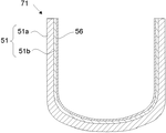
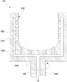
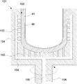
- FIG. 2 shows a schematic cross-sectional view of an example of a silica container according to the present invention.
- the silica container 71 according to the present invention has rotational symmetry, and the basic structure thereof includes a base 51 and an inner layer 56.
- the substrate 51 has rotational symmetry and has silica as a main component.
- the substrate 51 contains bubbles on the outer peripheral side 51a of the substrate, that is, has a porous white opaque layer portion, and is typically translucent to transparent on the inner peripheral side 51b of the substrate.
- the inner layer 56 is formed on the inner surface of the base 51 and is made of transparent silica glass.
- the total concentration of Li, Na, and K in the substrate 51 is 50 wt. ppm or less.
- the inner layer 56 contains Ca, Sr and Ba in a total concentration of 50 to 5000 wt.
- the light transmittance at a light wavelength of 600 nm when a sample having a thickness of 10 mm is cut out is 91.8 to 93.2%, more preferably 92.4 to 93.2%. It is.
- silica container of the present invention may further include other layers as long as it has at least the base 51 and the inner layer 56.
- the silica container 71 configured in this manner has sufficient temperature uniformity at low cost. That is, among the silica containers, at least the outer peripheral side 51a of the substrate is made of a porous opaque silica body, and at least the inner layer 56 is made of a thick transparent silica glass body substantially free of bubbles, thereby increasing the silica container 71. When used under temperature, the uniformity of the temperature inside the silica container 71 can be enhanced.
- the silica container 71 when used at a high temperature of 1400 to 1600 ° C. by containing at least one of Ca, Sr and Ba, particularly Ba, in the inner layer 56 as described above, the surface of the silica glass The portion can be recrystallized with cristobalite or the like. As a result, diffusion elution of alkali metal elements such as Na, K and Li contained in the base 51 of the silica container 71 can be prevented. It is possible to reduce the etching of the inner surface of the silica container 71 due to the containment such as the metal silicon melt processed in step (b).
- the inner layer 56 is made of 10-100 wt. By containing at a concentration of ppm, an impurity diffusion preventing effect can be further added and an alkaline earth metal element such as Ba can be more uniformly dissolved. Therefore, generation
- each concentration of Li, Na, K in the inner layer 56 is set to 60 wt. It is preferable to make the part of the silica container 71 in contact with the contained material sufficiently high in purity as ppb or less.
- the concentration of Ba in the inner layer 56 is set to 100 to 1000 wt. By setting it as ppm, the high impurity diffusion prevention effect, durability, etc. can be acquired more reliably.
- the inner surface layer portion (that is, the inner layer 56) of the silica container 71 needs to contain as little fine bubbles as possible.
- the reason for this is, for example, when the metallic silicon is melted in the silica container 71, the inner surface layer portion of the silica container is dissolved to some extent, but if the inner surface layer portion contains fine bubbles, As a result, for example, when processing a silicon wafer for solar use, voids and defects called voids and pinholes are generated in the wafer. Because.
- hydrogen gas is simultaneously contained when an element that promotes crystallization, such as the alkaline earth metal elements Ca, Sr, Ba, is included (dope).
- an element that promotes crystallization such as the alkaline earth metal elements Ca, Sr, Ba
- the particle diameter is 10 to 1000 ⁇ m
- Ca, Sr, and Ba are 50 to 5000 wt.
- a silica powder containing a total concentration of ppm and having a hydrogen molecule release amount of 3 ⁇ 10 16 to 3 ⁇ 10 19 molecules / g when heated to 1000 ° C. under vacuum is used.
- Ba is 100 to 1000 wt.
- ppm and hydrogen molecules are contained at 5 ⁇ 10 16 to 5 ⁇ 10 18 molecules / g. Also, Al is added to 10 to 100 wt. When it is contained in ppm, an alkaline earth metal element such as Ba can be dissolved more uniformly.
- alkaline earth metal elements Ca, Sr, Ba 50 to 5000 wt. a combination of ppm (preferably Ba 100 to 1000 wt. ppm) and hydrogen molecules 3 ⁇ 10 16 to 3 ⁇ 10 19 molecules / g (preferably 5 ⁇ 10 16 to 5 ⁇ 10 18 molecules / g), or in addition to these Al 10-100 wt.
- the combination of ppm is extremely important as a technique for uniformly dissolving the crystallization accelerator in silica glass without containing fine bubbles.
- silica fine crystals are generated in a large amount and uniformly on the surface of the silica glass. Is essential.
- silica glass produced from silica raw material powder heat-treated in a hydrogen gas-containing atmosphere tends to slow the growth rate of crystals such as cristobalite. Therefore, the silica powder containing Ba and the like is heated in a hydrogen gas-containing atmosphere to adjust the raw material powder, and when a silica container is produced from this raw material powder, a fine and dense recrystallized layer is formed when the silica container is used. It becomes possible to form.
- the silica raw powder heat-treated in the atmosphere containing hydrogen gas contains oxygen defects and hydrogen molecules, and some structural defects remain in the silica glass produced from this powder, and these structural defects are cristobalite. It is estimated that the crystal growth rate is moderately reduced. Therefore, in order to form a fine recrystallized layer on the inner surface of the silica container, it is necessary that the silica raw material powder contains a high concentration of hydrogen molecules together with a crystallization accelerator such as Ba.
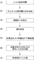
- FIG. 1 shows an outline of a method for producing silica powder according to the present invention.
- a powder made of silica having a particle size of 10 to 1000 ⁇ m is prepared as a raw material base material.
- the material of the raw material powder for forming the inner layer of the silica container include highly purified natural quartz powder, natural quartz powder, synthetic cristobalite powder, and synthetic silica glass powder. Crystalline silica powder is preferable for the purpose of reducing the amount of bubbles in the transparent layer, or synthetic powder is preferable for the purpose of obtaining a high-purity transparent layer.
- the particle size is preferably 100 to 500 ⁇ m. Purity is silica component (SiO 2 ) 99.9999 wt.
- each of the alkali metal elements Li, Na, K is 60 wt. ppb or less, preferably 20 wt. More preferably, it is ppb or less.
- each of Ti, V, Cr, Fe, Co, Ni, Cu, Zn, Mo, and W is 30 wt. ppb or less, preferably 10 wt. More preferably, it is ppb or less.
- an alkaline earth metal element is added to the silica powder as the raw material base material.
- at least one of calcium (Ca), strontium (Sr), and barium (Ba), preferably Ba is contained in the silica powder.
- an alkaline earth metal element chloride, acetate, nitrate or carbonate that dissolves in water or alcohol is selected prior to hydrogen molecule doping of the raw material powder, and an aqueous solution or alcohol solution of this compound.
- the silica raw material powder is immersed in this, and then dried to obtain a powder to which the specific element is added.
- the temperature of the hydrogen gas-containing atmosphere is lowered to at least 50 ° C. or less while maintaining the pressure of the hydrogen gas-containing atmosphere at 1 kgf / cm 2 or more.
- the gas mixed with hydrogen in the hydrogen gas-containing atmosphere is an inert gas such as nitrogen (N 2 ), argon (Ar), or helium (He).
- the silica powder according to the present invention can be produced.
- the inner layer 56 of the silica container 71 according to the present invention is formed using such silica powder as a raw material powder. That is, in the present invention, at least the raw material powder for forming the inner layer 56 has a particle size of 10 to 1000 ⁇ m and Ca, Sr, and Ba of 50 to 5000 wt.
- the inner layer 56 is formed using silica powder containing a total concentration of ppm and releasing hydrogen molecules of 3 ⁇ 10 16 to 3 ⁇ 10 19 molecules / g when heated to 1000 ° C. under vacuum. .
- silica container 71 as described above will be specifically described.
- a method for producing a silica container (solar grade crucible) that can be manufactured at low cost and can be used as a container for melting and single crystal pulling of metal silicon (Si), which is used as a material for photovoltaic power generation devices, etc. explain.
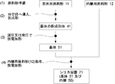
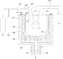
- FIG. 3 shows an outline of an example (first embodiment) of the method for producing the silica container 71 according to the present invention.
- substrates and the raw material powder 12 for inner layers which are silica particles are prepared (process 1).
- the silica powder according to the present invention described above is used as the inner layer raw material powder 12.
- the manufacturing method is as described above (for example, the method shown in FIG. 1).
- the base material powder 11 is a main constituent material of the base 51 in the silica container 71 (see FIG. 2) according to the present invention.
- This base material powder can be produced, for example, by crushing and sizing the silica lump as follows, but is not limited thereto.
- a natural silica lump (naturally produced crystal, quartz, silica, siliceous rock, opal stone, etc.) with a diameter of about 5 to 50 mm is heated in a temperature range of 600 to 1000 ° C. for about 1 to 10 hours in an air atmosphere.
- the natural silica mass is put into water, taken out after rapid cooling, and dried. This process facilitates the subsequent crushing and sizing process using a crusher or the like, but the process may proceed to the crushing process without performing the heating and quenching process.
- the natural silica mass is pulverized and sized by a crusher or the like, and the particle size is preferably adjusted to 10 to 1000 ⁇ m, more preferably 50 to 500 ⁇ m to obtain natural silica powder.
- this natural silica powder is put into a rotary kiln composed of a silica glass tube having an inclination angle, and the inside of the kiln is made into an atmosphere containing hydrogen chloride (HCl) or chlorine (Cl 2 ) gas, and is kept at 700 to 1100 ° C.
- the high-purity treatment is performed by heating for about 1 to 100 hours. However, in a product application that does not require high purity, the process may proceed to the next process without performing the purification process.
- the base material powder 11 obtained after the above steps is crystalline silica.
- amorphous silica glass scrap can be used as the base material powder 11.
- the particle size of the base material powder 11 is preferably 10 to 1000 ⁇ m, and more preferably 50 to 500 ⁇ m.
- the silica purity of the raw material powder 11 for substrate is 99.99 wt. % Or more, preferably 99.999 wt. % Or more is more preferable.
- the total value of Li, Na, and K is 50 wt. It is preferable to set it as ppm or less.
- substrates will be 99.999 wt. Even if it is a thing with comparatively low purity as% or less, the manufactured silica container can fully prevent the impurity contamination to the accommodation to accommodate. Therefore, a silica container can be manufactured at a lower cost than before.
- the base material powder 11 further contains Al, preferably 10 to 500 wt. It is good also as what is contained in the range of ppm.
- Al can be obtained by, for example, adding nitrate, acetate, carbonate, chloride or the like as water or an alcohol solution, putting silica powder in these solutions, immersing them, and then drying them.
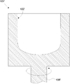
- FIG. 5 shows a schematic cross-sectional view of an outer mold that can be decompressed as an example of an outer mold for temporarily forming the raw material powder 11 for a substrate.
- the depressurizable outer mold 101 is made of, for example, a member such as graphite and has rotational symmetry.
- a decompression hole 103 is distributed and formed in the inner wall 102 of the decompressible outer mold 101.
- the decompression hole 103 is continuous with the decompression passage 104.
- a pressure reducing passage 105 also passes through a rotary shaft 106 for rotating the pressure-reducible outer mold 101, and vacuuming can be performed from here. It should be noted that a porous filter (not shown) is preferably attached to the hole 103.
- the base material powder 11 is introduced into the inner wall 102 of the depressurizable outer mold frame 101, and the base material powder 11 is temporarily formed into a predetermined shape corresponding to the shape of the inner wall 102 of the depressurizable outer mold frame 101. Let it be a temporary molded body 41 (see FIG. 7). Specifically, while rotating the depressurizable outer mold 101, the base material powder 11 is gradually put into the inner wall 102 of the depressurizable outer mold 101 from a raw material powder hopper (not shown), and centrifugal force is used. And molded into a container shape.
- the thickness of the temporary molded body 41 of the base body may be adjusted to a predetermined amount by bringing a plate-shaped inner mold (not shown) from the inside into contact with the rotating powder.
- the method for supplying the base material powder 11 to the depressurizable outer mold 101 is not particularly limited.
- a hopper provided with a stirring screw and a measuring feeder can be used.
- the base material powder 11 filled in the hopper is stirred with a stirring screw, and is supplied while adjusting the supply amount with a measuring feeder.
- the inner layer raw material powder 12 is introduced onto the inner surface of the temporary molded body 41 of the base, and the temporary Temporarily molding into a predetermined shape corresponding to the inner surface of the molded body 41 to form an inner-layer temporary molded body 46 (step 3).
- the method is the same as that for introducing the raw material powder 11 for the substrate. That is, while rotating the depressurizable outer mold 101, the inner layer raw material powder 12 is gradually introduced from the raw material powder hopper into the inner surface of the temporary molded body 41 of the base, and formed into a container shape using centrifugal force ( FIG. 11).
- the base 51 and the inner layer 56 are formed by a reduced pressure / discharge heating melting method (step 4).
- the pressure is reduced by the pressure reducing hole 103 formed in the pressure-reducible outer mold 101, so that the base temporary molded body 41 and the inner layer temporary molded body 46 are changed into the base body.
- the pressure is reduced from the outer peripheral side of the temporary molded body 41 and degassed, and heating is performed from the inside of the temporary molded body 41 of the base and the temporary molded body 46 of the inner layer by a discharge heating melting method.
- the outer peripheral portion of the substrate temporary molded body 41 is used as a sintered body, and the inner portion of the substrate temporary molded body 41 and the inner layer temporary molded body 46 are used as molten glass bodies to form the substrate 51 and the inner layer 56. .
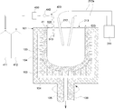
- the apparatus for forming the substrate 51 and the inner layer 56 includes a rotary motor (not shown) and a discharge heating melting (arc melting, arc discharge melting) in addition to the rotatable depressurizable outer mold 101 having the rotational axis symmetry described above.
- a carbon electrode (carbon electrode) 212 serving as a heat source, an electric wire 212a, a high-voltage power supply unit 211, a lid 213, and the like.
- components for adjusting the atmospheric gas supplied from the inside of the inner-layer temporary molded body 46 for example, an O 2 gas supply cylinder 411, an inert gas supply cylinder 412, a mixed gas supply pipe 420, and a dehumidifier 430.
- a dew point thermometer 440 or the like can be provided.
- oxygen gas is added in an amount of 1 to 30 vol. %, And can be performed in a mixed atmosphere with an inert gas.
- the carbon particles from the carbon electrode can be oxidized and gasified to CO or CO 2 , and a silica container with few carbon (C) fine particles can be obtained.
- It can also be carried out in an atmosphere which is air set at a dew point temperature of 10 ° C. to ⁇ 10 ° C. and controlled within a range of ⁇ 1 ° C. of the set temperature.
- the OH group content and moisture (H 2 O) content in the silica container can be reduced while being low in cost.
- dehumidification is performed to a predetermined dew point temperature or lower.
- a mixed gas containing two gases and an inert gas starts to be supplied from the inside of the temporary molded body 41 of the base and the temporary molded body 46 of the inner layer. Specifically, as shown in FIG.
- the O 2 gas from the O 2 gas supply cylinder 411, the inert gas supply cylinder 412 inert gas e.g., nitrogen (N 2), argon (Ar) And helium (He)
- N 2 nitrogen
- Ar argon
- He helium
- symbol 510 shows the flow of mixed gas.
- the dew point temperature can be set by an appropriate dehumidifying device or the like, and an appropriate dew point thermometer or the like can be used to measure the dew point temperature.
- FIG. 12 shows a mode in which the dehumidifying device 430 and the dew point thermometer 440 are incorporated in the mixed gas supply pipe 420.
- the present invention is not limited to this. .
- the gas in the depressurizable outer mold 101 it is preferable to ventilate the gas in the depressurizable outer mold 101 as described above.
- This ventilation can be performed, for example, by letting the atmospheric gas in the depressurizable outer mold 101 escape from the gap of the lid 213 to the outside.
- symbol 520 shows the flow of atmospheric gas accompanying ventilation.
- the vacuum pump for degassing is rotated while rotating the depressurizable outer mold 101 containing the temporary molded body 41 of the base and the temporary molded body 46 of the inner layer at a constant speed. (Not shown) is activated, pressure is reduced from the outside of the temporary molded body 41 through the pressure reducing hole 103 and the pressure reducing passages 104 and 105, and charging is started between the carbon electrodes 212.
- arc discharge (illustrated by reference numeral 220) is started between the carbon electrodes 212, the inner surface portions of the base temporary formed body 41 and the inner layer temporary formed body 46 are melted in a silica powder melting temperature range (about 1800 to 2000 ° C.). It is estimated) and melting starts from the outermost layer.
- the degree of vacuuming by the degassing vacuum pump increases (the pressure suddenly decreases), and the dissolved gas contained in the base material powder 11 and the inner layer raw material powder 12 is degassed.
- the change to the fused silica glass layer proceeds from the inside to the outside.
- the timing of evacuation is important, and strong evacuation should not be performed before the inner surface layer inside the container is vitrified.
- the initial degree of decompression is not so high and the vacuuming is gradually strengthened as the inner surface is melted into glass. Then, the inner layer and the inner half of the total thickness of the substrate are melted, the inner layer 56 is transparent silica glass, the inner peripheral side 51b of the substrate is a portion made of a transparent or translucent layer, and the outer peripheral portion of the substrate 51 (remaining) Heating by heating and depressurization by a vacuum pump are continued until 51a becomes sintered white opaque silica (opaque layer).
- the degree of vacuum is preferably 10 4 Pa or less, and more preferably 10 3 Pa or less. In this manner, the silica container 71 of the present invention shown in FIG. 2 can be obtained.
- the inner layer forming step in the second embodiment as described later may be further performed once or a plurality of times so that the inner layer 56 is composed of a plurality of transparent silica glass layers having different purities and additives.
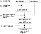
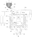
- the outline of another example (2nd embodiment) of the manufacturing method of the silica container 71 which concerns on this invention is shown in FIG.
- the manufacturing method of the silica container 71 according to this embodiment basically follows the contents shown in Patent Documents 6 and 7.
- the silica powder of the present invention produced as described above is used as the raw material powder (inner layer raw material powder 12) for forming the inner layer 56.
- substrates and the raw material powder 12 for inner layers which are silica particles are prepared (process 1). This step can be performed in the same manner as in the first embodiment described above.
- step 2 the base material powder 11 is introduced into an outer mold frame having rotational symmetry for molding (see FIG. 7) (step 2).
- This step can also be performed in the same manner as in the first embodiment described above.
- an outer mold 101 ′ as shown in FIG. 6 may be used instead of the depressurizable outer mold 101 shown in FIG. good.
- the outer mold 101 ′ is made of a member such as graphite and has rotational symmetry. It has a rotating shaft 106 'for rotating the outer mold 101', and the inner wall 102 'has no particular hole.
- a base 51 is formed by a reduced pressure / discharge heating melting method (step 3).
- the substrate temporary molded body 41 is converted into the substrate temporary molded body 41 by reducing the pressure through the decompression hole 103 formed in the depressurizable outer mold 101.
- the gas is depressurized from the outer peripheral side and degassed, and is heated from the inside of the temporary molded body of the substrate by a discharge heating melting method.
- the outer peripheral portion of the base preform 41 is a sintered body
- the inner portion of the base preform 41 is a molten glass body to form the base 51.
- the depressurization is not particularly performed, and a high temperature is applied from the inside of the temporary molded body 41 of the substrate by a discharge heating melting method.
- the substrate 51 is formed by heating.
- an aspect in which the base 51 is formed while reducing pressure using the pressure-reducible outer mold 101 will be mainly described. However, when the pressure is not reduced and normal pressure is used, the same process is performed except that pressure reduction is performed. Thus, the base 51 can be formed.
- the apparatus for forming the base 51 is not limited to the above-described rotatable depressurizable outer mold frame 101 (or the outer mold frame 101 ′) having the rotational axis symmetry.
- a rotation motor (not shown), and a carbon electrode (carbon electrode) 212 serving as a heat source for discharge heating melting (also referred to as arc melting or arc discharge melting), an electric wire 212a, a high-voltage power supply unit 211, a lid 213, and the like.
- components for adjusting the atmospheric gas supplied from the inside of the temporary molded body of the substrate for example, an O 2 gas supply cylinder 411, an inert gas supply cylinder 412, a mixed gas supply pipe 420, a dehumidifier 430, A dew point thermometer 440 or the like can be provided.
- oxygen gas is added in an amount of 1 to 30 vol. %, And can be performed in a mixed atmosphere with an inert gas.
- the carbon particles from the carbon electrode can be oxidized and gasified to CO or CO 2 , and a silica container with few carbon (C) fine particles can be obtained.
- It can also be carried out in an atmosphere which is air set at a dew point temperature of 10 ° C. to ⁇ 10 ° C. and controlled within a range of ⁇ 1 ° C. of the set temperature.
- the OH group content and moisture (H 2 O) content in the silica container can be reduced while being low in cost.
- an O 2 gas and an inert gas which are set to a predetermined dew point temperature or less by dehumidification
- the mixed gas containing is started to be supplied from the inside of the temporary molded body 41 of the base body.
- O 2 gas from the O 2 gas supply cylinder 411, the inert gas supply cylinder 412 inert gas e.g., nitrogen (N 2), argon (Ar) And helium (He)
- N 2 gas supply cylinder 412 inert gas e.g., nitrogen (N 2), argon (Ar) And helium (He)
- N 2 gas supply cylinder 412 inert gas e.g., nitrogen (N 2), argon (Ar) And helium (He)
- N 2 gas supply cylinder 412 inert gas e.g., nitrogen (N 2), argon (Ar) And helium (He)
- N 2 gas supply cylinder 412 inert gas e.g., nitrogen (N 2),
- the dew point temperature can be set by an appropriate dehumidifying device or the like, and an appropriate dew point thermometer or the like can be used to measure the dew point temperature.
- FIGS. 8 and 9 show a mode in which the dehumidifying device 430 and the dew point thermometer 440 are incorporated in the mixed gas supply pipe 420.
- the present invention is not limited to this, and the dew point temperature of the mixed gas is set within a predetermined range by dehumidification. I can do it.
- the gas in the depressurizable outer mold 101 it is preferable to ventilate the gas in the depressurizable outer mold 101 as described above.
- This ventilation can be performed, for example, by letting the atmospheric gas in the depressurizable outer mold 101 escape from the gap of the lid 213 to the outside.
- symbol 520 shows the flow of atmospheric gas accompanying ventilation.
- the vacuum pump for degassing (not shown) is started while rotating the depressurizable outer mold 101 containing the temporary molded body 41 of the base at a constant speed. Then, the pressure is reduced from the outside of the temporary molded body 41 through the pressure reducing hole 103 and the pressure reducing passages 104 and 105, and charging is started between the carbon electrodes 212.
- the inner surface portion of the temporary body 41 of the base body becomes the melting temperature range of silica powder (estimated to be about 1800 to 2000 ° C.), and the outermost layer portion Melting begins from
- the degree of vacuuming by the degassing vacuum pump is increased (the pressure is suddenly reduced), and the dissolved gas contained in the base material powder 11 is degassed to the fused silica glass layer. Changes from the inside to the outside. Also, the timing of evacuation is important, and strong evacuation should not be performed before the inner surface layer inside the container is vitrified.
- the initial degree of decompression is not so high and the vacuuming is gradually strengthened as the inner surface is melted into glass. Then, the inner half of the entire thickness of the base body is melted, the inner peripheral side 51b of the base body becomes a portion made of a transparent or translucent layer, and the outer peripheral portion (the remaining outer half) 51a of the base body 51 is sintered white. Heating by applying electricity and depressurization by a vacuum pump are continued until opaque silica (opaque layer) is obtained.
- the degree of vacuum is preferably 10 4 Pa or less, and more preferably 10 3 Pa or less.
- the silica powder (inner layer raw material powder 12), which is a raw material powder, is dispersed from the inside of the base 51 to form the inner layer, the inner side is formed by the discharge heating melting method.
- the inner layer 56 is formed on the inner surface of the substrate 51 by heating at a high temperature (step 4). In addition, you may make it the inner layer 56 consist of several transparent silica glass layers from which purity and an additive differ by repeating this process 4.
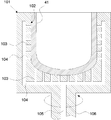
- a method of forming the inner layer 56 will be described with reference to FIG.
- the apparatus for forming the inner layer 56 on the inner surface of the base 51 is the same as in the previous step, the rotatable outer mold frame 101 on which the base 51 having rotational axis symmetry is installed, and a rotary motor (not shown).
- a raw material powder hopper 303 containing the inner layer raw material powder 12 for forming the inner layer 56, a stirring screw 304, a measuring feeder 305, a carbon electrode 212 serving as a heat source for discharge heating and melting, an electric wire 212a, a high voltage power supply unit 211, It consists of a lid 213 and the like.
- an O 2 gas supply cylinder 411, an inert gas supply cylinder 412, a mixed gas supply pipe 420, a dehumidifying device 430, a dew point thermometer 440, and the like. May be provided.
- the decompressable outer mold 101 is set to a predetermined rotation speed, and a high voltage is gradually applied from the high-voltage power supply unit 211.
- the inner layer raw material powder (high purity silica powder) 12 is sprayed from the upper part of the substrate 51.
- discharge is started between the carbon electrodes 212, and the inside of the substrate 51 is in the silica powder melting temperature range (estimated to be about 1800 to 2000 ° C.), so that the dispersed inner layer raw material powder 12 is fused silica particles. And adheres to the inner surface of the substrate 51.
- the carbon electrode 212, the raw material powder inlet, and the lid 213 installed in the upper opening of the base 51 have a mechanism that allows the position of the base 51 to be changed to some extent. By changing these positions, the base The inner layer 56 can be formed on the entire inner surface 51 with a uniform thickness.
- oxygen gas was added in an amount of 1 to 30 vol.
- the air can be used in a mixed atmosphere with an inert gas, and the dew point temperature is set to 10 ° C. to ⁇ 10 ° C. and is controlled within a range of ⁇ 1 ° C. of the set temperature. It can also be performed under an atmosphere.
- the mixed gas can be supplied from the inside of the substrate 51 through the mixed gas supply pipe 420.
- symbol 510 shows the flow of mixed gas.
- the gas in the depressurizable outer mold 101 can be ventilated as described above. This ventilation can be performed, for example, by letting the atmospheric gas in the depressurizable outer mold 101 escape from the gap of the lid 213 to the outside.
- symbol 520 shows the flow of atmospheric gas accompanying ventilation.
- the silica container 71 of the present invention can be obtained, but the silica container is washed as follows as necessary.
- silica container cleaning and drying For example, surface etching is performed with about 1 to 10% hydrofluoric acid aqueous solution (HF) for 5 to 30 minutes, then washed with pure water and dried in clean air to obtain a silica container.
- HF hydrofluoric acid aqueous solution
- the silica container 71 according to the present invention shown in FIG. 2 as described above can be manufactured.
- Example 1 In accordance with the method for producing silica powder and the method for producing a silica container of the present invention shown in FIG. 3, silica powder was produced as follows and a silica container was produced.
- the base material powder 11 a purity of 99.999 wt. %, A natural quartz powder having a particle size of 50 to 500 ⁇ m, and the inner layer raw material powder 12 has a particle size of 50 to 500 ⁇ m, Ba200 wt.
- a natural quartz powder of ppm dope and H 2 2 ⁇ 10 17 molecules / g was prepared.
- the raw material powder 12 for inner layers was manufactured as raw material powder for comprising the inner layer of a silica container through the process as shown in FIG. Specifically, first, a purity of 99.9999 wt. % High-purity natural quartz powder.
- this high-purity natural quartz powder was mixed with 25 wt.% Containing barium nitrate Ba (NO 3 ) 2 . It was immersed in a% ethyl alcohol aqueous solution and dried. Next, this quartz powder was put into a vacuum furnace with a stainless steel jacket, and the internal atmosphere was set to 100 vol. And heated at 400 ° C. for 3 hours while maintaining the pressure at 1 kgf / cm 2 (substantially the same as atmospheric pressure), and then cooled to room temperature 25 ° C. while maintaining the hydrogen gas atmosphere. Raw material powder 12 was produced.
- the raw material powder for the base and the raw material powder for the inner layer were integrally formed in the outer mold as follows. First, while rotating a rotating cylindrical graphite depressurizable outer mold 101 having a decompression hole 103 formed in the inner wall 102, the base material powder 11 is put into the inner wall 102 of the outer mold and predetermined. After adjusting the thickness, the inner layer raw material powder 12 was charged to form an inner layer temporary molded body 46 on the inner surface of the base temporary molded body 41. Next, the dew point is 7 ° C. ⁇ 1 ° C., that is, within the range of 6 ° C. to 8 ° C.
- the silica container 71 manufactured in this way is 3 wt. After washing with 25% aqueous hydrofluoric acid (HF) at 25 ° C. for 3 minutes, it was washed with pure water and dried.
- HF aqueous hydrofluoric acid
- Example 2 As in Example 1, except that the amount of Ba dope into the inner layer raw material powder 12 is 500 wt. ppm, hydrogen gas 100 vol. %, Pressure 9.9 kgf / cm 2 (about 9.9 atm), 400 ° C. for 3 hours, and the amount of H 2 dope was set to 2 ⁇ 10 18 molecules / g to produce silica container 71.
- Example 3 The silica container 71 was manufactured according to the manufacturing method (second embodiment) of the silica container shown in FIG.
- the base material powder 11 and the inner layer raw material powder 12 were produced in the same manner as in Example 1.
- the base 51 is sintered and melted by arc discharge heating in air at a normal pressure dew point of 7 ° C. ⁇ 1 ° C., and then the inner layer 56 is formed by spraying the inner layer raw material powder 12 from the upper part of the outer mold 101. However, it was carried out by arc discharge heating in normal pressure air with a dew point of 7 ° C. ⁇ 1 ° C.
- Example 4 The silica container 71 was manufactured according to the manufacturing method of the silica container shown in FIG. However, the production of the base material powder 11 and the inner layer raw material powder 12 was performed in the same manner as in Example 2.
- Example 5 A silica container was produced in substantially the same manner as in Example 3. However, 50 wt.
- the inner layer raw material powder 12 was doped with Al in addition to Ba and H 2 .
- the heating atmosphere when forming the base 51 and the inner layer 56 was a dew point temperature of 3 ° C. ⁇ 1 ° C.
- Example 6 As in Example 5, the silica container 71 was manufactured while the base 51 and the inner layer 56 were formed while the temporary molded body in the outer mold was decompressed and exhausted from the outside.
- Example 7 As in Example 5, except that the amount of Ba dope in the inner layer raw material powder 12 was reduced to 120 wt. ppm. Further, the silica container 71 was manufactured with H 2 as 4 ⁇ 10 17 molecules / g dope.
- Example 8 As in Example 5, except that the Ba dope amount of the inner layer raw material powder 12 is 100 wt. ppm, Sr doping amount 20 wt.
- the silica container 71 was manufactured by setting the dope of ppm and H 2 to 4 ⁇ 10 17 molecules / g.
- a silica container (silica crucible) was prepared according to a conventional method. That is, as the raw material powder for the substrate and the raw material powder for the inner layer, both particle diameters of 50 to 500 ⁇ m and purity of 99.9999 wt. % High-purity quartz powder.
- the substrate is formed by atmospheric pressure arc heating in air that is not adjusted for humidity, and the inner layer is heated by atmospheric arc discharge while spraying raw material powder from the upper part of the outer mold in the same air. Melted and formed.
- Comparative Example 2 As in Comparative Example 1, except that Ba was added to the inner layer raw material powder at 500 wt. A silica container was manufactured as a ppm dope.
- Comparative Example 3 As in Comparative Example 1, except that 30 wt. ppm doped, hydrogen gas 10 vol. % Nitrogen gas 90 vol. A silica container was manufactured by doping H 2 with 2 ⁇ 10 16 molecules / g by treatment at 400 ° C. for 3 hours with 1% mixed gas and 1 kgf / cm 2 (about 1 atm).
- Comparative Example 4 Similar to Comparative Example 1, except that the raw material powder for the substrate had a purity of 99.99 wt. A silica container was manufactured as a low-purity product with a% purity.
- Example 5 (Comparative Example 5) As in Example 1, however, a silica container was produced without adding hydrogen molecules to the inner layer raw material powder.
- Example 6 (Comparative Example 6) As in Example 1, however, a silica container was produced without adding Ba to the inner layer raw material powder.
- Particle size measurement method for each raw material powder Two-dimensional shape observation and area measurement of each raw material powder were performed with an optical microscope or an electron microscope. Next, assuming that the shape of the particle is a perfect circle, the diameter was calculated from the area value. This method was repeated statistically to obtain a value within the range of the particle size (in this range, 99 wt.% Or more of the raw material powder was included).
- Dew point temperature measurement Measured with a dew point thermometer. In addition, about each Example, it measured with the dew point thermometer 440 installed in the mixed gas supply pipe
- Impurity metal element concentration analysis When the impurity metal element concentration is relatively low (the glass is highly pure), plasma emission analysis (ICP-AES, Inductively Coupled Plasma-Atomic Emission Spectroscopy) or plasma mass spectrometry (ICP-MS, Inductively Coupled Pladded) When the impurity metal element concentration is relatively high (the glass is of low purity), atomic absorption spectrophotometry (AAS, Atomic Absorption Spectroscopy) was used.
- ICP-AES Inductively Coupled Plasma-Atomic Emission Spectroscopy
- ICP-MS Inductively Coupled Pladded
- Layer thickness measurement The thickness of the substrate and the inner layer was determined by measuring the cross section of the container at half the full height (200 mm height) of the side wall of the silica container.
- OH group concentration measurement Samples were cut and polished from the transparent portion of the substrate and the inner layer, and each was performed by infrared absorption spectrophotometry. Conversion to the OH group concentration follows the literature below. Dodd, D.D. M.M. and Fraser, D.A. B. (1966), “Optical determination of OH in fused silica.” Journal of Applied Physics, vol. 37, P.I. 3911.
- the raw material powder for the inner layer (silica powder as raw material) is used as it is, and the amount of hydrogen gas released from the inner layer of the silica container is measured as a state of a granular silica glass sample adjusted to a particle size of 100 ⁇ m to 1 mm. Went.
- the amount of gas released from the inner layer raw material powder or sample at 1000 ° C. under vacuum was measured with a mass spectrometer. Details follow the literature below.
- the hydrogen molecule H 2 was expressed as the number of released molecules per unit weight (hydrogen molecule / g glass), assuming that the entire amount was released. Nasu, S .; et al. (1990) “Gas release of various kinds of vitreous silica”, Journal of Illuminating Engineering of Japan, vol. 74, no. 9, pp. 595-600.
- Light transmittance measurement A glass sample having dimensions of 5 mm ⁇ 5 mm ⁇ thickness of 11 mm was cut out from the inner layer, and both end surfaces were finished by parallel optical polishing with a thickness of 10 mm. After that, the visible light transmittance meter using a mercury lamp as a light source is used to measure the linear transmittance of the glass sample at 600 nm (the incident light is 100%, the reflection of the sample surface, the back reflection inside the sample, and the absorption of the sample itself). This is a value obtained by subtracting, and is called Optical transmission). This value reflects the amount of bubbles in the sample and the uniform solubility of the dope element.
- Silicon single crystal continuous pulling (multi pulling) evaluation Purity 99.99999999 wt. % Metal polysilicon was added, the temperature was raised to obtain a silicon melt, and then the silicon single crystal was pulled three times repeatedly (multi-pulling), and the success rate of single crystal growth was evaluated.
- the pulling conditions were as follows: the inside of the CZ apparatus was an argon (Ar) gas 100% atmosphere at a pressure of 10 3 Pa, the pulling rate was 1 mm / min, the rotation speed was 10 rpm, the silicon single crystal dimensions were 150 mm in diameter and 150 mm in length. The operation time for one batch was about 12 hours.
- the evaluation classification of the success rate of three times of single crystal growth was as follows. Successful 3 times ⁇ (Good) Successful ⁇ (Slightly bad) 1 time or less x (defect)
- etching resistance of silica containers Sample of the silica container after the multi-pulling of the silicon single crystal three times, with the silica container side wall from the lower part of the silicon melting surface, with all the thicknesses in the thickness direction so that the inner wall has a dimension of 100 mm ⁇ 100 mm Was cut out. Next, the etching amount of the inner wall portion of the inner layer was determined by measuring the sample cross section with a scale. The etched thickness of the inner layer is less than 3 mm ⁇ (good) The etched thickness of the inner layer is 3 mm to less than 5 mm. Etched thickness of inner layer is 5mm or more x (defect)
- Manufacturing cost (relative) evaluation of silica container The production cost of the silica container was evaluated. In particular, the total values of silica raw material costs, melting energy costs, etc. were relatively evaluated. Conventional manufacturing costs were based on Comparative Example 1. Low cost ⁇ (Less than 50% of conventional manufacturing cost) Medium cost ⁇ (50 to less than 100% of conventional manufacturing cost) Cost is high ⁇ (Conventional manufacturing cost is 100%)
- the single pulling of the silicon single crystal can be performed with a high success rate, and the generation of voids and pinholes can be made equal to or lower than those in Comparative Examples 1 and 2.
- etching resistance could be provided at the same time.
- Comparative Example 3 the alkaline earth metal element and the hydrogen molecule concentration of the inner layer raw material powder were low, and the etching resistance was insufficient.
- Comparative Example 4 the silica container could be manufactured at low cost, but there were many problems such as generation of voids and pinholes, low etching resistance, and large impurity diffusion.
- Comparative Example 5 the amount of Ba added to the inner layer raw material powder was large, but since no hydrogen molecules were added, it is considered that voids and pinholes were frequently generated.
- Comparative Example 6 on the contrary, the amount of hydrogen molecules added to the inner layer raw material powder was large, but Ba was not added, so the etching resistance of the silica container was low, and the impurity diffusion was not sufficiently suppressed. It is thought that it became a thing.
- the present invention is not limited to the above embodiment.
- the above embodiment is merely an example, and the present invention has the same configuration as that of the technical idea described in the claims of the present invention, and any device that exhibits the same function and effect is the present invention. It is included in the technical scope of the invention.
Abstract
Priority Applications (4)
| Application Number | Priority Date | Filing Date | Title |
|---|---|---|---|
| CN201080036839.0A CN102482137B (zh) | 2009-10-14 | 2010-09-01 | 二氧化硅粉、二氧化硅容器及该粉或容器的制造方法 |
| KR1020127004097A KR101374545B1 (ko) | 2009-10-14 | 2010-09-01 | 실리카 분말 및 실리카 용기 그리고 그 제조방법 |
| EP10823157.2A EP2489642A4 (fr) | 2009-10-14 | 2010-09-01 | Poudre de silice, contenant en silice, et procédé de production de la poudre de silice et du contenant |
| US13/140,982 US8460769B2 (en) | 2009-10-14 | 2010-09-01 | Powdered silica, silica container, and method for producing them |
Applications Claiming Priority (2)
| Application Number | Priority Date | Filing Date | Title |
|---|---|---|---|
| JP2009237686A JP4969632B2 (ja) | 2009-10-14 | 2009-10-14 | シリカ粉及びシリカ容器並びにそれらの製造方法 |
| JP2009-237686 | 2009-10-14 |
Publications (1)
| Publication Number | Publication Date |
|---|---|
| WO2011045888A1 true WO2011045888A1 (fr) | 2011-04-21 |
Family
ID=43875945
Family Applications (1)
| Application Number | Title | Priority Date | Filing Date |
|---|---|---|---|
| PCT/JP2010/005375 WO2011045888A1 (fr) | 2009-10-14 | 2010-09-01 | Poudre de silice, contenant en silice, et procédé de production de la poudre de silice et du contenant |
Country Status (7)
| Country | Link |
|---|---|
| US (1) | US8460769B2 (fr) |
| EP (1) | EP2489642A4 (fr) |
| JP (1) | JP4969632B2 (fr) |
| KR (1) | KR101374545B1 (fr) |
| CN (1) | CN102482137B (fr) |
| TW (1) | TWI454425B (fr) |
| WO (1) | WO2011045888A1 (fr) |
Families Citing this family (15)
| Publication number | Priority date | Publication date | Assignee | Title |
|---|---|---|---|---|
| JP4922355B2 (ja) * | 2009-07-15 | 2012-04-25 | 信越石英株式会社 | シリカ容器及びその製造方法 |
| JP4951057B2 (ja) * | 2009-12-10 | 2012-06-13 | 信越石英株式会社 | シリカ容器及びその製造方法 |
| JP5774400B2 (ja) * | 2010-08-12 | 2015-09-09 | 株式会社Sumco | シリカ粉の評価方法、シリカガラスルツボ、シリカガラスルツボの製造方法 |
| CN103597128A (zh) * | 2012-05-15 | 2014-02-19 | 信越石英株式会社 | 单晶硅提拉用二氧化硅容器及其制造方法 |
| US20140150715A1 (en) * | 2012-05-16 | 2014-06-05 | Shin-Etsu Quartz Products Co., Ltd. | Single-crystal silicon pulling silica container and producing method thereof |
| US9469819B2 (en) * | 2013-01-16 | 2016-10-18 | Clearsign Combustion Corporation | Gasifier configured to electrodynamically agitate charged chemical species in a reaction region and related methods |
| CN103584635B (zh) * | 2013-11-21 | 2015-08-26 | 河海大学 | 自供电显水温保温杯 |
| CN104068715A (zh) * | 2014-06-20 | 2014-10-01 | 郭裴哲 | 一种智能水杯 |
| EP3218317B1 (fr) | 2014-11-13 | 2018-10-17 | Gerresheimer Glas GmbH | Filtre à particules de machine de formage de verre, unité de piston, tête de soufflage, support de tête de soufflage et machine de formage de verre adaptée audit filtre ou le comprenant |
| JP6480827B2 (ja) * | 2015-08-03 | 2019-03-13 | 信越石英株式会社 | 水素ドープシリカ粉の保管方法及びシリコン単結晶引上げ用石英ガラスるつぼの製造方法 |
| EP3205630B1 (fr) * | 2016-02-12 | 2020-01-01 | Heraeus Quarzglas GmbH & Co. KG | Materiau diffuseur en verre de quartz synthetique et procede de fabrication d'un corps de moulage en etant totalement ou partiellement constitue |
| JP6659408B2 (ja) * | 2016-03-07 | 2020-03-04 | クアーズテック株式会社 | シリコン単結晶引上げ用シリカガラスルツボの製造方法 |
| JP6713382B2 (ja) * | 2016-08-30 | 2020-06-24 | クアーズテック株式会社 | 石英ガラスルツボの製造方法、及び石英ガラスルツボ |
| KR20230011937A (ko) * | 2020-05-20 | 2023-01-25 | 닛테츠 케미컬 앤드 머티리얼 가부시키가이샤 | 구상 결정질 실리카 입자, 및 그 제조 방법 |
| KR102647080B1 (ko) * | 2021-11-03 | 2024-03-13 | 국립목포대학교산학협력단 | 비정질 실리카 나노 분말을 이용한 투명한 실리카 소결체의 제조방법 |
Citations (14)
| Publication number | Priority date | Publication date | Assignee | Title |
|---|---|---|---|---|
| JPH0422861B2 (fr) | 1987-12-03 | 1992-04-20 | Shinetsu Handotai Kk | |
| JPH0729871B2 (ja) | 1987-12-03 | 1995-04-05 | 信越半導体 株式会社 | 単結晶引き上げ用石英るつぼ |
| JPH07206451A (ja) | 1993-12-29 | 1995-08-08 | Nippon Steel Corp | 合成石英ガラスの製造方法 |
| JPH07277744A (ja) | 1994-04-04 | 1995-10-24 | Nippon Steel Corp | 合成石英ガラスの製造方法 |
| JPH07277743A (ja) | 1994-04-04 | 1995-10-24 | Nippon Steel Corp | 合成石英ガラスの製造方法 |
| JPH082932A (ja) | 1994-06-20 | 1996-01-09 | Shinetsu Quartz Prod Co Ltd | 石英ガラスルツボとその製造方法 |
| JP2001261353A (ja) * | 2000-03-17 | 2001-09-26 | Toshiba Ceramics Co Ltd | 石英ガラスルツボ用合成シリカガラス粉及びその製造方法、並びに合成シリカガラス粉を用いた石英ガラスルツボの製造方法 |
| JP2002362932A (ja) | 2001-03-24 | 2002-12-18 | Shinetsu Quartz Prod Co Ltd | SiO2含有複合材料の製造方法、その製造方法により得られる複合材料及び複合材料の使用 |
| JP2003095678A (ja) * | 2001-07-16 | 2003-04-03 | Heraeus Shin-Etsu America | シリコン単結晶製造用ドープ石英ガラスルツボ及びその製造方法 |
| JP2003335513A (ja) * | 2002-05-17 | 2003-11-25 | Shinetsu Quartz Prod Co Ltd | 水素ドープシリカ粉及びその製造方法、並びにそれを用いた石英ガラスルツボ及びその製造方法 |
| JP2004131380A (ja) | 2002-09-20 | 2004-04-30 | Heraeus Quarzglas Gmbh & Co Kg | 不透明石英ガラス複合材の製造方法、前記方法による複合材、およびその利用法 |
| JP2005145731A (ja) * | 2003-11-12 | 2005-06-09 | Kuramoto Seisakusho Co Ltd | 結晶化石英ルツボ |
| JP2007326780A (ja) | 2007-09-18 | 2007-12-20 | Shinetsu Quartz Prod Co Ltd | シリコン単結晶引上げ用石英ガラスルツボの製造方法 |
| JP2008081398A (ja) * | 2006-09-28 | 2008-04-10 | Heraeus Shin-Etsu America Inc | バリウムドープされた内壁を有するシリカガラスるつぼ |
Family Cites Families (6)
| Publication number | Priority date | Publication date | Assignee | Title |
|---|---|---|---|---|
| US4935046A (en) | 1987-12-03 | 1990-06-19 | Shin-Etsu Handotai Company, Limited | Manufacture of a quartz glass vessel for the growth of single crystal semiconductor |
| JPH0720645A (ja) | 1993-06-30 | 1995-01-24 | Ricoh Co Ltd | 電子写真感光体及びその製造方法 |
| DE10041582B4 (de) * | 2000-08-24 | 2007-01-18 | Heraeus Quarzglas Gmbh & Co. Kg | Quarzglastiegel sowie Verfahren zur Herstellung desselben |
| US20030012899A1 (en) | 2001-07-16 | 2003-01-16 | Heraeus Shin-Etsu America | Doped silica glass crucible for making a silicon ingot |
| US7365037B2 (en) * | 2004-09-30 | 2008-04-29 | Shin-Etsu Quartz Products Co., Ltd. | Quartz glass having excellent resistance against plasma corrosion and method for producing the same |
| US7427327B2 (en) * | 2005-09-08 | 2008-09-23 | Heraeus Shin-Etsu America, Inc. | Silica glass crucible with barium-doped inner wall |
-
2009
- 2009-10-14 JP JP2009237686A patent/JP4969632B2/ja active Active
-
2010
- 2010-09-01 WO PCT/JP2010/005375 patent/WO2011045888A1/fr active Application Filing
- 2010-09-01 US US13/140,982 patent/US8460769B2/en not_active Expired - Fee Related
- 2010-09-01 EP EP10823157.2A patent/EP2489642A4/fr not_active Withdrawn
- 2010-09-01 CN CN201080036839.0A patent/CN102482137B/zh not_active Expired - Fee Related
- 2010-09-01 KR KR1020127004097A patent/KR101374545B1/ko not_active IP Right Cessation
- 2010-09-08 TW TW099130347A patent/TWI454425B/zh not_active IP Right Cessation
Patent Citations (14)
| Publication number | Priority date | Publication date | Assignee | Title |
|---|---|---|---|---|
| JPH0422861B2 (fr) | 1987-12-03 | 1992-04-20 | Shinetsu Handotai Kk | |
| JPH0729871B2 (ja) | 1987-12-03 | 1995-04-05 | 信越半導体 株式会社 | 単結晶引き上げ用石英るつぼ |
| JPH07206451A (ja) | 1993-12-29 | 1995-08-08 | Nippon Steel Corp | 合成石英ガラスの製造方法 |
| JPH07277744A (ja) | 1994-04-04 | 1995-10-24 | Nippon Steel Corp | 合成石英ガラスの製造方法 |
| JPH07277743A (ja) | 1994-04-04 | 1995-10-24 | Nippon Steel Corp | 合成石英ガラスの製造方法 |
| JPH082932A (ja) | 1994-06-20 | 1996-01-09 | Shinetsu Quartz Prod Co Ltd | 石英ガラスルツボとその製造方法 |
| JP2001261353A (ja) * | 2000-03-17 | 2001-09-26 | Toshiba Ceramics Co Ltd | 石英ガラスルツボ用合成シリカガラス粉及びその製造方法、並びに合成シリカガラス粉を用いた石英ガラスルツボの製造方法 |
| JP2002362932A (ja) | 2001-03-24 | 2002-12-18 | Shinetsu Quartz Prod Co Ltd | SiO2含有複合材料の製造方法、その製造方法により得られる複合材料及び複合材料の使用 |
| JP2003095678A (ja) * | 2001-07-16 | 2003-04-03 | Heraeus Shin-Etsu America | シリコン単結晶製造用ドープ石英ガラスルツボ及びその製造方法 |
| JP2003335513A (ja) * | 2002-05-17 | 2003-11-25 | Shinetsu Quartz Prod Co Ltd | 水素ドープシリカ粉及びその製造方法、並びにそれを用いた石英ガラスルツボ及びその製造方法 |
| JP2004131380A (ja) | 2002-09-20 | 2004-04-30 | Heraeus Quarzglas Gmbh & Co Kg | 不透明石英ガラス複合材の製造方法、前記方法による複合材、およびその利用法 |
| JP2005145731A (ja) * | 2003-11-12 | 2005-06-09 | Kuramoto Seisakusho Co Ltd | 結晶化石英ルツボ |
| JP2008081398A (ja) * | 2006-09-28 | 2008-04-10 | Heraeus Shin-Etsu America Inc | バリウムドープされた内壁を有するシリカガラスるつぼ |
| JP2007326780A (ja) | 2007-09-18 | 2007-12-20 | Shinetsu Quartz Prod Co Ltd | シリコン単結晶引上げ用石英ガラスルツボの製造方法 |
Non-Patent Citations (4)
| Title |
|---|
| DODD, D. M.; FRASER, D. B.: "Optical determination of OH in fused silica", JOURNAL OF APPLIED PHYSICS, vol. 37, 1966, pages 3911 |
| NASU, S ET AL.: "Gas release of various kinds of vitreous silica", JOURNAL OF ILLUMINATING ENGINEERING INSTITUTE OF JAPAN, vol. 74, no. 9, 1990, pages 595 - 600 |
| See also references of EP2489642A4 |
| V. S. KHOTIMCHENKO ET AL.: "Determining the content of hydrogen dissolved in quartz glass using the methods of Raman scattering and mass spectrometry", JOURNAL OF APPLIED SPECTROSCOPY, vol. 46, no. 6, 1987, pages 632 - 635, XP009149953, DOI: doi:10.1007/BF00661243 |
Also Published As
| Publication number | Publication date |
|---|---|
| KR20120041223A (ko) | 2012-04-30 |
| TWI454425B (zh) | 2014-10-01 |
| JP2011084428A (ja) | 2011-04-28 |
| CN102482137B (zh) | 2014-09-10 |
| EP2489642A1 (fr) | 2012-08-22 |
| CN102482137A (zh) | 2012-05-30 |
| US8460769B2 (en) | 2013-06-11 |
| JP4969632B2 (ja) | 2012-07-04 |
| TW201119943A (en) | 2011-06-16 |
| KR101374545B1 (ko) | 2014-03-17 |
| EP2489642A4 (fr) | 2013-10-30 |
| US20110256330A1 (en) | 2011-10-20 |
Similar Documents
| Publication | Publication Date | Title |
|---|---|---|
| JP4969632B2 (ja) | シリカ粉及びシリカ容器並びにそれらの製造方法 | |
| JP4951057B2 (ja) | シリカ容器及びその製造方法 | |
| JP4951040B2 (ja) | シリカ容器及びその製造方法 | |
| JP4903288B2 (ja) | シリカ容器及びその製造方法 | |
| JP4907735B2 (ja) | シリカ容器及びその製造方法 | |
| JP4922355B2 (ja) | シリカ容器及びその製造方法 | |
| JP5462423B1 (ja) | 単結晶シリコン引き上げ用シリカ容器及びその製造方法 | |
| EP2687623A1 (fr) | Conteneur en silice pour la croissance de silicium monocristallin, et procédé pour fabriquer celui-ci | |
| JP5308594B1 (ja) | 単結晶シリコン引き上げ用シリカ容器及びその製造方法 | |
| WO2013171937A1 (fr) | Récipient en silice destiné à préparer du silicium monocristallin et procédé de fabrication associé | |
| WO2013171955A1 (fr) | Récipient en silice destiné à préparer du silicium monocristallin et procédé de fabrication associé |
Legal Events
| Date | Code | Title | Description |
|---|---|---|---|
| WWE | Wipo information: entry into national phase |
Ref document number: 201080036839.0 Country of ref document: CN |
|
| 121 | Ep: the epo has been informed by wipo that ep was designated in this application |
Ref document number: 10823157 Country of ref document: EP Kind code of ref document: A1 |
|
| WWE | Wipo information: entry into national phase |
Ref document number: 13140982 Country of ref document: US |
|
| REEP | Request for entry into the european phase |
Ref document number: 2010823157 Country of ref document: EP |
|
| WWE | Wipo information: entry into national phase |
Ref document number: 2010823157 Country of ref document: EP |
|
| ENP | Entry into the national phase |
Ref document number: 20127004097 Country of ref document: KR Kind code of ref document: A |
|
| NENP | Non-entry into the national phase |
Ref country code: DE |