WO2011045841A1 - 電池モジュール - Google Patents
電池モジュール Download PDFInfo
- Publication number
- WO2011045841A1 WO2011045841A1 PCT/JP2009/005389 JP2009005389W WO2011045841A1 WO 2011045841 A1 WO2011045841 A1 WO 2011045841A1 JP 2009005389 W JP2009005389 W JP 2009005389W WO 2011045841 A1 WO2011045841 A1 WO 2011045841A1
- Authority
- WO
- WIPO (PCT)
- Prior art keywords
- battery
- battery module
- unit
- positive
- tab
- Prior art date
- Legal status (The legal status is an assumption and is not a legal conclusion. Google has not performed a legal analysis and makes no representation as to the accuracy of the status listed.)
- Ceased
Links
Images


Classifications
-
- H—ELECTRICITY
- H01—ELECTRIC ELEMENTS
- H01M—PROCESSES OR MEANS, e.g. BATTERIES, FOR THE DIRECT CONVERSION OF CHEMICAL ENERGY INTO ELECTRICAL ENERGY
- H01M10/00—Secondary cells; Manufacture thereof
- H01M10/42—Methods or arrangements for servicing or maintenance of secondary cells or secondary half-cells
- H01M10/48—Accumulators combined with arrangements for measuring, testing or indicating the condition of cells, e.g. the level or density of the electrolyte
- H01M10/482—Accumulators combined with arrangements for measuring, testing or indicating the condition of cells, e.g. the level or density of the electrolyte for several batteries or cells simultaneously or sequentially
-
- H—ELECTRICITY
- H01—ELECTRIC ELEMENTS
- H01M—PROCESSES OR MEANS, e.g. BATTERIES, FOR THE DIRECT CONVERSION OF CHEMICAL ENERGY INTO ELECTRICAL ENERGY
- H01M50/00—Constructional details or processes of manufacture of the non-active parts of electrochemical cells other than fuel cells, e.g. hybrid cells
- H01M50/20—Mountings; Secondary casings or frames; Racks, modules or packs; Suspension devices; Shock absorbers; Transport or carrying devices; Holders
- H01M50/204—Racks, modules or packs for multiple batteries or multiple cells
- H01M50/207—Racks, modules or packs for multiple batteries or multiple cells characterised by their shape
- H01M50/211—Racks, modules or packs for multiple batteries or multiple cells characterised by their shape adapted for pouch cells
-
- H—ELECTRICITY
- H01—ELECTRIC ELEMENTS
- H01M—PROCESSES OR MEANS, e.g. BATTERIES, FOR THE DIRECT CONVERSION OF CHEMICAL ENERGY INTO ELECTRICAL ENERGY
- H01M50/00—Constructional details or processes of manufacture of the non-active parts of electrochemical cells other than fuel cells, e.g. hybrid cells
- H01M50/50—Current conducting connections for cells or batteries
- H01M50/502—Interconnectors for connecting terminals of adjacent batteries; Interconnectors for connecting cells outside a battery casing
- H01M50/503—Interconnectors for connecting terminals of adjacent batteries; Interconnectors for connecting cells outside a battery casing characterised by the shape of the interconnectors
-
- H—ELECTRICITY
- H01—ELECTRIC ELEMENTS
- H01M—PROCESSES OR MEANS, e.g. BATTERIES, FOR THE DIRECT CONVERSION OF CHEMICAL ENERGY INTO ELECTRICAL ENERGY
- H01M50/00—Constructional details or processes of manufacture of the non-active parts of electrochemical cells other than fuel cells, e.g. hybrid cells
- H01M50/50—Current conducting connections for cells or batteries
- H01M50/502—Interconnectors for connecting terminals of adjacent batteries; Interconnectors for connecting cells outside a battery casing
- H01M50/509—Interconnectors for connecting terminals of adjacent batteries; Interconnectors for connecting cells outside a battery casing characterised by the type of connection, e.g. mixed connections
-
- H—ELECTRICITY
- H01—ELECTRIC ELEMENTS
- H01M—PROCESSES OR MEANS, e.g. BATTERIES, FOR THE DIRECT CONVERSION OF CHEMICAL ENERGY INTO ELECTRICAL ENERGY
- H01M50/00—Constructional details or processes of manufacture of the non-active parts of electrochemical cells other than fuel cells, e.g. hybrid cells
- H01M50/50—Current conducting connections for cells or batteries
- H01M50/531—Electrode connections inside a battery casing
- H01M50/536—Electrode connections inside a battery casing characterised by the method of fixing the leads to the electrodes, e.g. by welding
-
- H—ELECTRICITY
- H01—ELECTRIC ELEMENTS
- H01M—PROCESSES OR MEANS, e.g. BATTERIES, FOR THE DIRECT CONVERSION OF CHEMICAL ENERGY INTO ELECTRICAL ENERGY
- H01M50/00—Constructional details or processes of manufacture of the non-active parts of electrochemical cells other than fuel cells, e.g. hybrid cells
- H01M50/50—Current conducting connections for cells or batteries
- H01M50/569—Constructional details of current conducting connections for detecting conditions inside cells or batteries, e.g. details of voltage sensing terminals
-
- H—ELECTRICITY
- H01—ELECTRIC ELEMENTS
- H01M—PROCESSES OR MEANS, e.g. BATTERIES, FOR THE DIRECT CONVERSION OF CHEMICAL ENERGY INTO ELECTRICAL ENERGY
- H01M10/00—Secondary cells; Manufacture thereof
- H01M10/04—Construction or manufacture in general
- H01M10/0436—Small-sized flat cells or batteries for portable equipment
-
- H—ELECTRICITY
- H01—ELECTRIC ELEMENTS
- H01M—PROCESSES OR MEANS, e.g. BATTERIES, FOR THE DIRECT CONVERSION OF CHEMICAL ENERGY INTO ELECTRICAL ENERGY
- H01M10/00—Secondary cells; Manufacture thereof
- H01M10/04—Construction or manufacture in general
- H01M10/0468—Compression means for stacks of electrodes and separators
-
- H—ELECTRICITY
- H01—ELECTRIC ELEMENTS
- H01M—PROCESSES OR MEANS, e.g. BATTERIES, FOR THE DIRECT CONVERSION OF CHEMICAL ENERGY INTO ELECTRICAL ENERGY
- H01M10/00—Secondary cells; Manufacture thereof
- H01M10/05—Accumulators with non-aqueous electrolyte
- H01M10/052—Li-accumulators
-
- H—ELECTRICITY
- H01—ELECTRIC ELEMENTS
- H01M—PROCESSES OR MEANS, e.g. BATTERIES, FOR THE DIRECT CONVERSION OF CHEMICAL ENERGY INTO ELECTRICAL ENERGY
- H01M2200/00—Safety devices for primary or secondary batteries
-
- Y—GENERAL TAGGING OF NEW TECHNOLOGICAL DEVELOPMENTS; GENERAL TAGGING OF CROSS-SECTIONAL TECHNOLOGIES SPANNING OVER SEVERAL SECTIONS OF THE IPC; TECHNICAL SUBJECTS COVERED BY FORMER USPC CROSS-REFERENCE ART COLLECTIONS [XRACs] AND DIGESTS
- Y02—TECHNOLOGIES OR APPLICATIONS FOR MITIGATION OR ADAPTATION AGAINST CLIMATE CHANGE
- Y02E—REDUCTION OF GREENHOUSE GAS [GHG] EMISSIONS, RELATED TO ENERGY GENERATION, TRANSMISSION OR DISTRIBUTION
- Y02E60/00—Enabling technologies; Technologies with a potential or indirect contribution to GHG emissions mitigation
- Y02E60/10—Energy storage using batteries
Definitions
- the present invention relates to a battery module in which a plurality of unit batteries are stacked and sealed with a film-like exterior material.
- a secondary battery having a high energy density uses a battery sealed with a film-like exterior material instead of the conventional metal exterior material.
- a battery sealed with a film-like exterior material has high energy efficiency per volume or weight, and is therefore suitable for applications that require a large current, such as power supplies for electric tools, electric bicycles, and electric vehicles. Further, it has a feature that it is easy to produce a battery module or a battery pack in which a plurality of unit batteries are stacked and electrically connected.
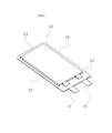
- FIG. 5 is a perspective view illustrating a battery sealed with a film-shaped exterior material. As shown in FIG. 5, the positive electrode and the negative electrode are laminated through a separator, sealed together with an electrolyte with a film-shaped packaging material, and the positive electrode tab 21 and the negative electrode tab 22 are drawn out to heat the film-shaped packaging material.
- the unit battery 20 is formed by welding and forming a heat welding portion 23 around the battery element.
- the secondary battery such as a lithium ion secondary battery expands due to the pressure of the gas generated inside the battery.
- an abnormality occurs in a battery module in which a plurality of unit batteries are stacked and connected, there is a problem that the battery module is deformed.
- Patent Document 1 In order to easily dissipate the gas generated inside the unit battery, it has been proposed to destroy the film-shaped exterior material by providing a sharp protrusion on the inner surface of the case containing the unit battery. For example, see Patent Document 1.
- Patent Document 2 In addition, it has been proposed that a case containing a battery module is provided with a protrusion having a through hole, and gas generated from the inside of the film-shaped exterior member to the outside of the case is diffused through the through hole.
- the unit battery is formed by providing a protrusion on the inner surface of the exterior case.
- a battery having a protrusion for ensuring that the film-shaped exterior material is broken when expanded is limited to a battery that is adjacent to the protrusion or has a reach in the protrusion shape. For this reason, it is difficult to eliminate the possibility of deformation of the battery module due to expansion if other unit batteries continue to expand even when the pressure of only the unit battery within the reach of the protrusion is released.
- the battery module of the present invention is a long battery pack in which a plurality of unit cells each having a battery element sealed with a film-like exterior material are stacked and electrically connected in series, parallel, or series-parallel. It is a battery module in which at least one belt-like annular frame is arranged in the center in the vertical direction.
- the positive input / output line is connected to the positive connection tab joined to the positive end tab of the assembled battery, and the negative input / output line is connected to the negative connection tab joined to the negative end tab of the assembled battery.
- the detection line is connected to the intermediate connection tab joined to either the positive electrode tab or the negative electrode tab located at both ends of the assembled battery, and the junction between the positive electrode tab and the negative electrode tab of each unit battery, and is taken out. Battery module.
- the battery voltage detection line is the battery module connected to and extracted from a chip fuse in which a plurality of electrically independent fuses are formed on an insulating plate.
- the positive electrode active material of the unit battery is a lithium manganese composite oxide.
- the belt-like annular frame is made of a synthetic resin material, a metal material, or both a synthetic resin material and a metal material.
- an insulating resin plate is provided on an upper surface and a lower surface of a laminated surface of the assembled battery, and an insulating adhesive tape is attached to a side surface.
- the band-shaped annular frame that presses the assembled battery in the stacking direction is attached, so that overcharging and the like are performed. Even when the pressure inside the unit battery sealed with a film-like exterior material rises in the event of an abnormality, expansion in the stacking direction is restricted, so the heat-sealed part of the film-like exterior material that seals the unit battery, the film-like exterior
- the pressure release valve attached to the material or the easily breakable portion formed in the film-like exterior material cannot withstand the increase in internal pressure and breaks, and the pressure inside the battery is released.
- the assembled battery inside the battery module does not expand greatly, deformation of the battery module housing due to expansion of the assembled battery can be prevented. Can be eliminated. Further, in the present invention, it is only necessary to attach a belt-like annular frame that presses in the stacking direction of the assembled battery, so that a large change in the assembly process is unnecessary, and what is conventionally used in the battery module housing is also used. It can be realized by using. Furthermore, it is not necessary for the battery case to take special measures for the battery module to give strength against swelling of the assembled battery.
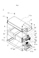
- FIG. 1 is an exploded perspective view for explaining one embodiment of the battery module of the present invention.
- FIG. 2 is a diagram illustrating an embodiment of the electrical wiring of the battery module of the present invention.
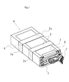
- FIG. 3 is a diagram illustrating another embodiment of the battery module of the present invention.
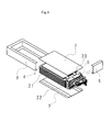
- FIG. 4 is a perspective view illustrating an assembly process of the assembled battery.
- FIG. 5 is an exploded perspective view for explaining the electrical connection of the assembled battery.
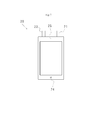
- FIG. 6 is a perspective view for explaining one embodiment of a unit battery sealed with a film-shaped exterior material.
- FIG. 7 is a perspective view for explaining another embodiment of the unit battery sealed with a film-shaped exterior material.
- FIG. 1 is an exploded perspective view for explaining one embodiment of the battery module of the present invention.
- the battery module 1 includes an assembled battery 4 in which a plurality of unit cells 20 are stacked in battery module housings 11a and 11b.
- Metal materials such as synthetic resin such as polycarbonate and ABS resin, aluminum, mild steel, and stainless steel can be used for the casings 11a and 11b of the battery module.
- the battery module housings 11 a and 11 b are coupled to each other by screws 12.
- a synthetic resin material is used as a member constituting the casing, it is possible to prevent a short circuit when a portion to which a voltage is applied comes into contact with the casing.
- the battery module 1 shown in this example six unit batteries 20 are connected in series to form an assembled battery 4.
- the shape, number of connections, and electrical connection method of the unit batteries can be changed as appropriate according to the purpose of use.
- the battery protection plate 7 formed of a synthetic resin material such as polycarbonate is bonded with a double-sided adhesive tape, and the adhesive tapes 8 and 9 are attached around the side surface to insulate and fix the assembled battery 4.
- the assembled battery 4 is placed in the frame of the band-shaped annular frame 2, and the band-shaped annular frame 2 is arranged at the center in the length direction of the assembled battery, and is housed in the casings 11a and 11b.
- the battery module 1 is assumed.
- annular frame made of a metal ring such as nickel or stainless steel, or a metal band connected in a ring by resistance welding, laser welding, ultrasonic welding or the like, or nylon, polyethylene, polypropylene
- those molded with a synthetic resin material such as a fluororesin can be used.
- annular frame 2 can make it easy to mount
- the annular frame body does not need to be in close contact with the assembled battery, and may be in a state of being in close contact when the assembled battery is slightly expanded so as to have an effect of suppressing further expansion.
- the battery module 1 includes a positive-side input / output line 54 of the assembled battery 4, a negative-side input / output line 55 of the assembled battery 4, and a battery voltage detection line 60 drawn to monitor the voltage of each unit battery.
- the positive input / output line 54 is provided with a current fuse 57 for short circuit protection, and the battery voltage detection line 60 is connected with a chip fuse 61 for preventing a short circuit of the voltage detection line.
- a chip fuse in which a plurality of electrically independent fuses 62 are formed on an insulating plate, electrical connection of a plurality of voltage detection lines is facilitated, and assembly is reliably performed in a short time. Can do.
- the casing is provided with an input / output line external connection connector 59 and a battery voltage detection line external connection connector 66 for connecting a device using a battery module, a battery pack, or the like.
- FIG. 2 is a diagram illustrating an embodiment of the electrical wiring of the battery module of the present invention.
- the assembled battery 4 is configured by connecting six unit batteries 20 in series.
- a positive-side input / output line 54 drawn from the positive electrode of the unit battery located at one end of the stack of the assembled battery 4, and a negative-side input / output drawn from the negative electrode of the unit battery located at the other end of the laminated body of the assembled battery
- the line 55 is connected, and the positive-side input / output line 54 is connected to the input / output line external connector 59 via the current fuse 57 and is connected to the battery protection circuit board.
- a battery voltage detection line 60 is connected to each positive electrode side of the unit battery, and is connected to six fuses 62 that are electrically independent from each other via an input side connector 61 a of the chip fuse 61. ing.
- the output side battery voltage detection line 64 connected to the output side connector 61b of the chip fuse 61 is connected to the battery voltage detection line external connection connector 66, and is connected to the battery protection circuit via the connector.
- the series number of unit batteries constituting the assembled battery can be appropriately set according to the voltage and current required by the battery-using device.
- typical voltages for battery-operated devices there are 12V and 24V systems, but in the case of lithium ion secondary batteries, 3 to 4 batteries are connected in series in the 12V system, It is preferable to connect 6-8 pieces in series. Further, by changing the number of series connections, it is possible to cope with various voltages including 36V, 42V and the like.
- FIG. 3 is a diagram for explaining another embodiment of the battery module of the present invention, and is a diagram for explaining the battery module with the casing removed.
- the battery pack 4 is provided with one band-like annular frame 2 at the center in the longitudinal direction of the battery, whereas FIG. Two pieces are arranged at intervals in the part.
- the number of strip-shaped annular frames is two. Not limited to this, an arbitrary number can be arranged according to the size of the battery.
- the annular frame is arranged in the central portion in the longitudinal direction of the unit cell has been described. However, by arranging the annular frame in the central portion in the longitudinal direction that is greatly deformed by an increase in internal pressure. The deformation of the battery module can be effectively prevented.
- FIG. 4 is a perspective view illustrating an assembly process of the assembled battery. After a predetermined number of unit cells 21 sealed with a film-like exterior material are stacked and the positive electrode tab 22 and the negative electrode tab 23 are connected, an insulating property having elasticity such as rubber sponge is formed above and below the positive electrode tab and the negative electrode tab. A spacer 5 is arranged. Next, the battery protection plates 7 formed of an insulating resin material such as polycarbonate are adhered to the upper and lower sides of the assembled battery 4 to which the unit battery 21 is connected, and the adhesive tapes 8 and 9 are pasted around the side surfaces. Insulate and fix the battery pack.
- an insulating property having elasticity such as rubber sponge
- FIG. 5 is an exploded perspective view for explaining the electrical connection of the assembled battery.
- FIG. 5 is a diagram for explaining a case where a predetermined number of unit cells 21 sealed by a film-shaped exterior material are stacked and connected in series, and two of the first and second layers from the upper layer, and the bottom layer It is the figure which showed one and omitted the middle.
- a positive electrode connection tab 71 is joined to the positive electrode tab 21 a of the uppermost unit battery 20 a, and the positive electrode side input / output line 54 and the battery voltage detection line 60 are connected to the positive electrode connection tab 71.
- the intermediate connection tab 73 is disposed between the negative electrode tab 22a of the uppermost unit battery 20a and the positive electrode tab 22b of the second layer, and the three members are integrally joined.
- a battery voltage detection line 60 is connected to the intermediate connection tab.
- a negative electrode connection tab 72 is joined to the negative electrode tab 22 f of the unit battery 20 f located in the lowest layer, and a negative electrode side input / output line is connected to the negative electrode connection tab 72.
- the positive electrode side input / output line 54 and the battery voltage detection line 60 are connected.
- the intermediate connection tab 73 is disposed between the negative electrode tab 22a of the uppermost unit battery 20a and the positive electrode tab 22b of the second layer, and the three members are integrally joined.
- a battery voltage detection line 60 is connected to the intermediate connection tab. Also, a negative electrode connection tab 72 is joined to the negative electrode tab 22 f of the unit battery 20 f located in the lowest layer, and a negative electrode side input / output line 55 is connected to the negative electrode connection tab 72.
- the positive input / output line 54 and the battery voltage detection line 60 are positively connected without being connected to the positive input / output line 54, the negative input / output line 55, the positive electrode tab and the negative electrode tab of the unit battery by soldering.
- the negative electrode side input / output line 55 is connected to the negative electrode connection tab 72 by soldering to the tab 71
- the positive electrode connection tab 71 and the positive electrode tab are joined by resistance welding, and the negative electrode connection tab is similarly resistance welded to the negative electrode tab.
- the other battery voltage detection line 60 is connected to the intermediate connection tab 73 by soldering in advance, the positive electrode tab and the negative electrode tab are arranged at the junction, and the intermediate connection tab, the positive electrode tab, and the negative electrode are connected.
- the tab is preferably welded by resistance welding. In this way, after connecting to the positive electrode connection tab 71, the negative electrode connection tab 72, and the intermediate connection tab 73 by soldering, the soldering heat adversely affects the battery by connecting to the positive electrode tab or the negative electrode tab by welding. This can be prevented.
- FIG. 6 is a perspective view for explaining one embodiment of a unit battery sealed with a film-shaped exterior material.
- a unit battery sealed with a film-shaped packaging material is manufactured by laminating a positive electrode, a negative electrode, and a separator, and sealing a battery element filled with an electrolytic solution with a film-shaped packaging material.
- the unit cell 20 has a positive electrode tab 21 and a negative electrode tab 22 drawn out from the same ridge of the unit cell, and the unit cell 20 sealed with a film-shaped packaging material is surrounded by the heat of the film-shaped packaging material.
- a welded portion 23 is formed and sealed.
- the positive electrode tab and the negative electrode tab are not limited to those drawn from the same ridge as described above, and may be drawn from opposite sides.
- the positive electrode is prepared by applying a slurry in which particles of a lithium transition metal composite oxide are dispersed with a carbonaceous conductivity imparting material such as carbon black together with a binder onto an aluminum foil current collector.
- a lithium transition metal composite oxide a lithium manganese composite oxide can be used.
- the lithium manganese composite oxide may be not only an oxide containing only lithium and manganese but also a composite oxide containing other elements.
- the negative electrode can be produced by applying a slurry obtained by stirring and agitating graphite, amorphous carbon powder, silicon, etc., doped with lithium and undoped with lithium, onto a copper foil.
- a heat-sealable polyethylene film is arranged on the inner surface of the unit battery, and a polyethylene terephthalate, polyamide film, etc. having a high strength is arranged on the outer surface, and the inner and outer synthetic resin films are placed between them. It is preferable to use a flexible laminated film in which aluminum foil is disposed and laminated.
- FIG. 7 is a perspective view for explaining another embodiment of the unit battery sealed with a film-shaped exterior material.
- the unit battery 20 shown in FIG. 7 has a safety valve 24 that releases pressure by cleaving when the internal pressure of the battery rises at the periphery.
- the portion where the safety valve 24 is disposed is preferably provided at the peripheral edge other than the interterminal sealing portion 25 between the positive electrode tab 21 and the negative electrode tab 22, and at the end in the length direction opposite to the interterminal sealing portion.
- the safety valve 24 is formed by heat-sealing a film that is cleaved at a pressure lower than that of the film-shaped packaging material into a hole portion provided in the film-shaped packaging material, or by cutting into the film-shaped packaging material to form a thin portion or the like. Can be formed.
- a portion that is cleaved by a pressure lower than the joint portion by thermal fusion of the film-like exterior material, and by providing the unit battery with an annular frame the battery module is deformed when the internal pressure increases. Pressure can be safely released.
- Example 1 The unit battery sealed with a film-like packaging material is obtained by dissolving lithium manganate as a positive electrode active material, graphite as a negative electrode active material, and LiPF 6 as an electrolyte solution in a mixed solvent of ethylene carbonate (EC) and diethyl carbonate (DEC).
- EC ethylene carbonate
- DEC diethyl carbonate
- a positive electrode tab and a negative electrode tab were drawn out from the same ridge, and a product having a length of 158 mm ⁇ width of 82 mm ⁇ thickness of 5.6 mm was produced.
- unit cells are stacked so that the negative electrode tabs overlap each other on the positive electrode tab of each unit cell, and a polycarbonate plate having a length of 160 mm, a width of 80 mm, and a thickness of 0.5 mm is interposed between the unit cells. Placed and joined with double-sided adhesive tape.
- the positive electrode tab of the unit battery disposed at one end is connected to the positive electrode side input / output line 54 connected to the fuse and the positive electrode side connection tab soldered to the battery voltage detection line 60. Joined by welding.
- an intermediate connection tab in which a battery voltage detection line is solder-connected is disposed between the negative electrode tab of the unit cell and the positive electrode tab of the adjacent unit cell, and is integrally joined by resistance welding.
- an intermediate connection tab in which battery voltage detection wires are connected by soldering is disposed between the negative electrode tab and the positive electrode tab of the second to sixth unit cells and connected by resistance welding.
- a negative electrode side connection tab in which the negative electrode side input / output line was solder-connected was joined to the other end, that is, the negative electrode tab of the unit cell located at the sixth position by resistance welding.
- a spacer made of a rubber sponge having a length of 20 mm, a width of 30 mm, and a thickness of 2 mm was insulated above and below the positive electrode tab and the negative electrode tab with a double-sided adhesive tape so as not to expose each tab.
- a battery protection plate made of polycarbonate 160 mm long, 82 mm wide, and 0.5 mm high is adhered to the upper and lower surfaces of the assembled battery stack with double-sided adhesive tape, and the adhesive tape is attached around the side of the assembled battery.
- the assembled battery was insulated and fixed.
- the produced assembled battery had a length of 160.2 mm, a width of 82.1 mm, and a thickness of 36.5 mm.
- a nickel plate having a width of 10 mm and a thickness of 0.2 mm was formed in a central portion in the length direction, and a rectangular annular body having an inner dimension of 84 mm in width and 38.5 mm in length was arranged at intervals of 30 mm. Placed in place. Subsequently, the battery voltage output line connector was connected to the chip fuse connector, and the chip fuse connector was connected to the external connection connector. Also, a battery module was obtained by attaching connectors of the positive input / output line and the negative input / output line.
- Example 2 An assembled battery was produced in the same manner as in Example 1. A band-shaped annular frame body formed by processing an annular nickel material having a width of 13 mm ⁇ thickness of 0.3 mm so that the inner dimension is 84 mm ⁇ 38.5 mm is arranged at the center in the length direction of the assembled battery. Thereafter, the battery module was housed in a casing made of polycarbonate.
- Example 3 An assembled battery was produced in the same manner as in Example 1. Two strip-shaped annular frames made of polycarbonate by injection molding so as to have a width of 15 mm, a thickness of 2 mm, and an inner dimension of 84 mm ⁇ 38.5 mm were arranged at 30 mm intervals at the center in the longitudinal direction of the assembled battery. Thereafter, the battery module was housed in a casing made of polycarbonate.
- Comparative Example 1 A unit battery was produced in the same manner as in Example 1 and housed in a casing made of polycarbonate to obtain a battery module.
Landscapes
- Chemical & Material Sciences (AREA)
- Chemical Kinetics & Catalysis (AREA)
- Electrochemistry (AREA)
- General Chemical & Material Sciences (AREA)
- Engineering & Computer Science (AREA)
- Manufacturing & Machinery (AREA)
- Battery Mounting, Suspending (AREA)
- Connection Of Batteries Or Terminals (AREA)
Abstract
Description
エネルギー密度が大きな二次電池では、これまでの金属製の外装材に代えてフィルム状外装材で封口した電池が用いられているようになっている。
フィルム状外装材で封口した電池は、容積、あるいは重量当たりのエネルギー効率が大きいので、電動工具、電動自転車、電気自動車の電源用途のように大電流が必要である用途に適している。また、単位電池の複数個を積層して電気的に接続した電池モジュールあるいは電池パックを作製しやすいと言う特徴を有している。
図5に示すように、正極電極および負極電極をセパレータを介して積層して電解質と共にフィルム状外装材で封口して、正極タブ21、負極タブ22を外部に引出して、フィルム状外装材を熱溶着し、電池要素の周囲に熱溶着部23を形成して単位電池20としている。
また、電池モジュールを収納したケースには貫通孔を有する突起物を設け、貫通孔を通じてフィルム状外装材の内部からケースの外部へ発生した気体を放散することが提案されている。例えば、特許文献2参照。
本発明は、フィルム状外装材で封口した単位電池が、内部の圧力の上昇によって変形した場合にも正極タブと負極タブが電気的に接触することがない電池モジュールを提供することを課題とするものである。
前記単位電池の正極活物質が,リチウムマンガン複合酸化物である前記の電池モジュールである。
前記組電池の積層面の上面および下面に絶縁樹脂板を有し、側面に絶縁性粘着テープを貼り付けた前記の電池モジュールである。
その結果、電池モジュール内部の組電池が大きく膨張することがないので、組電池の膨張による電池モジュールの筐体の変形を防止することができるので、電池タブ同士が接触して短絡する可能性をなくすことができる。
また、本発明では、組電池の積層方向に押圧する帯状の環状枠体を取り付けるのみで、組立工程の大きな変更が不要であるとともに、電池モジュールの筐体にも従来から使用しているものを用いることによって実現することができる。
更には、電池モジュールに対しては、組電池の膨れに対する強度を持たせるための格別の対策を外装ケースに施す必要がなくなる。
図1は、本発明の電池モジュールの一実施態様を説明する分解斜視図である。
電池モジュール1は、電池モジュールの筐体11a、11b内に複数の単位電池20を積層した組電池4を有している。電池モジュールの筐体11a、11bは、ポリカーボネート、ABS樹脂等の合成樹脂、アルミニウム、軟鋼、ステンレス鋼等の金属材料を用いることができる。電池モジュールの筐体11a、11bはビス12によって相互に結合されている。
筐体を構成する部材として合成樹脂材料を用いた場合には、電圧を印加した部分が筐体と接触した場合に短絡を防止することが可能である。一方、放熱特性と筐体の強度が必要な場合には金属材料を用いることが好ましい。
この例で示した電池モジュール1は、6個の単位電池20を直列に接続して組電池4を形成している。単位電池の形状、接続個数、電気的接続方法は使用目的に応じて適宜変更することが可能である。
次いで、組電池4には、帯状の環状枠体2の枠内に入れて、組電池の長さ方向の中央部に帯状の環状枠体2を配置し、筐体11a、11bに収納されて電池モジュール1とする。
また、環状枠体は組電池に密着している必要はなく、組電池がわずかに膨張した際に密着された状態となり、さらなる膨張を抑制する作用を果たすものであれば良い。
正極側入出力線54には、短絡時保護用の電流ヒューズ57が設けられており、電池電圧検出線60には電圧検出線の短絡防止用のチップフューズ61が接続されている。
このように、絶縁板上に電気的に独立した複数個のフューズ62を形成したチップフューズを用いることによって、複数の電圧検出線の電気的接続が容易となり、組み立てを確実に短時間に行うことができる。
また、筐体には、電池モジュールを使用する機器、あるいは電池パック等とを接続する入出力線外部接続コネクタ59および電池電圧検出線外部接続コネクタ66が設けられている。
図2に示した例では、6個の単位電池20を直列に接続して組電池4を構成している。
組電池4の積層体の一端に位置する単位電池の正極から引き出された正極側入出力線54、前記組電池の積層体の他端に位置する単位電池の負極から引き出された負極側入出力線55が接続されており、正極側入出力線54は電流フューズ57を介して、入出力線外部接続コネクタ59に接続されており、電池保護回路基板へ接続される。
一方、単位電池のそれぞれの正極側には、電池電圧検出線60が接続されており、チップヒューズ61の入力側コネクタ61aを介して、相互に電気的に独立した6個のヒューズ62に接続されている。
チップヒューズ61の出力側コネクタ61bに接続された出力側電池電圧検出線64が電池電圧検出線外部接続コネクタ66へ接続されており、コネクタを介して電池保護回路へと接続される。
図1で示した電池モジュールでは、組電池4に帯状の環状枠体2が、電池の長手方向の中央部に1個設けたものであるのに対して、図3で示したものは、中央部に間隔を設けて2個配置したものである。
このように、帯状の環状枠体を2個配置することにより大きな組電池においても電池の内部圧力の膨張による変形を抑制することが可能であり、帯状の環状枠体の数は、2個に限らず、電池の大きさに応じて任意の個数を配置することができる。
また、以上の説明では、環状枠体は、単位電池の長手方向の中央部に配置する例について説明したが、内部圧力の増大によっる変形を大きく受ける長手方向の中央部に配置することによって電池モジュールの変形を効果的に防止することができる。
フィルム状外装材によって封口した単位電池21を所定の個数だけ積層して、正極タブ22、負極タブ23を接続した後に、正極タブ、負極タブの上下には、ゴムスポンジ等の弾性を有する絶縁性スペーサ5が配置される。
次いで、単位電池21が接続された組電池4の上下に、ポリカーボネート等の絶縁樹脂材で成形された電池保護板7を両面粘着テープで接着し、側面周囲に粘着テープ8、9を貼り付けて組電池の絶縁と固定を行う。
図5は、フィルム状外装材によって封口した単位電池21を所定の個数だけ積層して直列接続する場合を説明する図であり、上層から1層目と2層目の2個と、最下層の1個を示し、中間を省略した図である。
最上層の単位電池20aの正極タブ21aには、正極接続タブ71が接合されており、正極接続タブ71に、正極側入出力線54、および電池電圧検出線60を接続されている。
一方、最上層の単位電池20aの負極タブ22aと、第2層目の正極タブ22bは、間に、中間接続タブ73を配置して三者が一体に接合されている。そして、中間接続タブには、電池電圧検出線60が接続されている。
また、最下層に位置する単位電池20fの負極タブ22fには、負極接続タブ72が接合されており、負極接続タブ72には、負極側入出力線が接続されている。
このように、正極側入出力線54、および電池電圧検出線60を接続されている。
一方、最上層の単位電池20aの負極タブ22aと、第2層目の正極タブ22bは、間に、中間接続タブ73を配置して三者が一体に接合されている。そして、中間接続タブには、電池電圧検出線60が接続されている。
また、最下層に位置する単位電池20fの負極タブ22fには、負極接続タブ72が接合されており、負極接続タブ72には、負極側入出力線55が接続されている。
このように、正極接続タブ71、負極接続タブ72、中間接続タブ73に半田付によって接続した後に、正極タブあるいは負極タブと溶接によって接続することによって半田付けの熱が電池に対して悪影響を及ぼすことを防止することができる。
フィルム状外装材で封口した単位電池は、正極電極、負極電極、セパレータを積層して、電解液を充填した電池要素をフィルム状外装材で封口することによって製造される。
この例では、単位電池20は、正極タブ21と負極タブ22が、単位電池の同一の稜から引き出されており、フィルム状外装材で封口した単位電池20は、周囲にフィルム状外装材の熱溶着部23を形成して封口されている。
正極タブおよび負極タブは、上記のように同一の稜から引き出されたものに限らず、対向辺から引き出されたものでも良い。
リチウム遷移金属複合酸化物としては、リチウムマンガン複合酸化物を用いることができる。リチウムマンガン複合酸化物を用いた場合には、リチウムコバルト複合酸化物を使用した電池に比べて充電時の安全性が高いので個々の単位電池の保護回路を簡単なものとすることができる。したがって、電池モジュールを小型化することが可能となる。
リチウムマンガン複合酸化物は、リチウムとマンガンのみを含有する酸化物のみではなく、他の元素を含む複合酸化物であっても良い。
図7で示した単位電池20は、周縁部に電池の内部圧力が上昇した場合に開裂によって圧力を開放する安全弁24を有している。
安全弁24を配置する部分は、正極タブ21と負極タブ22との間の端子間封口部25の以外の周縁部に設けることが好ましく、端子間封口部と反対側の長さ方向の端部に位置する封口部に設けることによって、圧力の増大時の端子への影響を小さくし、速やかに圧力を開放することができる。
安全弁24は、フィルム状外装材に比べて低い圧力で開裂するフィルムをフィルム状外装材に設けた穴の部分に熱融着したり、フィルム状外装材に切れ込み、薄肉部等を形成することによって形成することができる。
このように、フィルム状外装材の熱融着による接合部よりも低い圧力によって開裂する部分を設けるとともに、単位電池に環状枠体を設けることによって、内部圧力の増大時に電池モジュールの変形を生じることなく安全に圧力を開放することができる。
実施例1
フィルム状外装材で封口した単位電池は、正極活物質としてマンガン酸リチウム、負極活物質として黒鉛、電解液としてLiPF6をエチレンカーボネート(EC)とジエチルカーボネート(DEC)の混合溶媒に溶解したものを用い、正極タブ、負極タブを同一の稜から引き出した縦158mm×横82mm×厚さ5.6mmのものを作製した。
また、各単位電池の正極タブに対しては、負極タブが重なるように6個の単位電池を積層し、単位電池の間には、縦160mm、横80mm、厚さ0.5mmのポリカーボネート板を配置し、両面粘着テープにより接合した。
同様にして、第二番目から第六番目に位置する単位電池の負極タブと正極タブの間に、電池電圧検出線を半田接続した中間接続タブを配置して抵抗溶接によって接続した。
他端、すなわち六番目に位置する単位電池の負極タブには、負極側入出力線を半田接続した負極側接続タブを抵抗溶接によって接合した。
更に、組電池の積層面の上面、下面には、縦160mm、横82mm、高さ0.5mmのポリカーボネートからなる電池保護板を両面粘着テープで接着し、組電池の側面周囲に粘着テープを貼り付けて組電池の絶縁と固定を行った。
作製した組電池は、縦160.2mm、横82.1mm、厚さ36.5mmであった。
次いで、ポリカーボネートからなる筐体に収納して、電池電圧出力線のコネクタをチップフューズのコネクタに接続するとともに、チップフューズのコネクタと外部接続用コネクタとを接続した。また、正極側入出力線、負極側入出力線のコネクタを取り付けて電池モジュールとした。
実施例1と同様に組電池を作製した。この組電池の長さ方向の中央部に幅13mm×厚さ0.3mmの環状のニッケル材を内側寸法が84mm×38.5mmとなるように加工した帯状の環状枠体を配置した。その後、ポリカーボネートからなる筐体に収納し電池モジュールとした。
実施例1と同様に組電池を作製した。幅15mm、厚さ2mm、内側寸法が84mm×38.5mmとなるようにポリカーボネートを射出成形した帯状の環状枠体を組電池の長さ方向の中央部に30mm間隔で2箇所配置した。その後、ポリカーボネートからなる筐体に収納し電池モジュールとした。
実施例1と同様に単位電池を作製し、ポリカーボネートからなる筐体に収納し電池モジュールとした。
2 帯状の環状枠体、2a 環状枠体の角部
4 組電池
5 絶縁性スペーサ
7 電池保護板
8,9 粘着テープ
11a、11b 筐体
12 ビス
20 単位電池
21 正極タブ
22 負極タブ
23 熱溶着部
24 安全弁
25 端子間封口部
54 正極側入出力線
55 負極側入出力線
57 電流ヒューズ
59 入出力線外部接続コネクタ
60 電池電圧検出線
61 チップフューズ
62 ヒューズ
64 出力側電池電圧検出線
66 電圧検出線外部接続コネクタ
71 正極接続タブ
72 負極接続タブ
73 中間接続タブ
Claims (6)
- 電池要素をフィルム状外装材によって封口した単位電池の複数個を積層して、直列、並列、あるいは直並列に電気的接続した組電池の長さ方向の中央部に帯状の環状枠体が少なくとも一個配置されていることを特徴とする電池モジュール。
- 正極側入出力線は、組電池の正極端部タブに接合した正極接続タブに接続され、負極側入出力線は、組電池の負極端部タブに接合した負極接続タブに接続され、電池電圧検出線は、組電池の両端部に位置する正極接続タブ、負極接続タブのいずれかと、各単位電池の正極タブと負極タブとの接合部に接合した中間接続タブに接続されて取り出されたことを特徴とする請求項1記載の電池モジュール。
- 前記電池電圧検出線は、絶縁板上に電気的に独立した複数個のフューズを形成したチップフューズに接続されて取り出されたことを特徴とする請求項1または2記載の電池モジュール。
- 前記単位電池の正極活物質が,リチウムマンガン複合酸化物であることを特徴とする請求項1から3のいずれか1項記載の電池モジュール。
- 前記帯状の環状枠体が合成樹脂材料、金属材料、あるいは合成樹脂材料と金属材料の両者からなることを特徴とする請求項1から4のいずれか1項記載の電池モジュール。
- 前記組電池の積層面の上面および下面に絶縁樹脂板を有し、側面に絶縁性粘着テープを貼り付けたことを特徴とする請求項1から5のいずれか1項記載の電池モジュール。
Priority Applications (3)
| Application Number | Priority Date | Filing Date | Title |
|---|---|---|---|
| PCT/JP2009/005389 WO2011045841A1 (ja) | 2009-10-15 | 2009-10-15 | 電池モジュール |
| CN2009801619459A CN102549798A (zh) | 2009-10-15 | 2009-10-15 | 电池模块 |
| US13/496,134 US20120171527A1 (en) | 2009-10-15 | 2009-10-15 | Battery module |
Applications Claiming Priority (1)
| Application Number | Priority Date | Filing Date | Title |
|---|---|---|---|
| PCT/JP2009/005389 WO2011045841A1 (ja) | 2009-10-15 | 2009-10-15 | 電池モジュール |
Publications (1)
| Publication Number | Publication Date |
|---|---|
| WO2011045841A1 true WO2011045841A1 (ja) | 2011-04-21 |
Family
ID=43875901
Family Applications (1)
| Application Number | Title | Priority Date | Filing Date |
|---|---|---|---|
| PCT/JP2009/005389 Ceased WO2011045841A1 (ja) | 2009-10-15 | 2009-10-15 | 電池モジュール |
Country Status (3)
| Country | Link |
|---|---|
| US (1) | US20120171527A1 (ja) |
| CN (1) | CN102549798A (ja) |
| WO (1) | WO2011045841A1 (ja) |
Cited By (5)
| Publication number | Priority date | Publication date | Assignee | Title |
|---|---|---|---|---|
| JP2013089488A (ja) * | 2011-10-19 | 2013-05-13 | Yazaki Corp | 電源装置 |
| JP2016503228A (ja) * | 2013-05-15 | 2016-02-01 | エルジー・ケム・リミテッド | 新規な構造の電池モジュールアセンブリー |
| JP2016508659A (ja) * | 2013-05-15 | 2016-03-22 | エルジー・ケム・リミテッド | 新規な構造の電池モジュールアセンブリー |
| JP2017076579A (ja) * | 2015-10-16 | 2017-04-20 | オートモーティブエナジーサプライ株式会社 | 電池システムおよび電池パック |
| WO2019163839A1 (ja) * | 2018-02-20 | 2019-08-29 | 積水化学工業株式会社 | 耐火積層体及びバッテリー |
Families Citing this family (20)
| Publication number | Priority date | Publication date | Assignee | Title |
|---|---|---|---|---|
| WO2014076740A1 (ja) * | 2012-11-16 | 2014-05-22 | 川崎重工業株式会社 | 電動乗物用バッテリパック |
| CN103337668B (zh) * | 2013-05-21 | 2017-10-10 | 东莞新能源科技有限公司 | 一种提高锂离子二次电池安全性的方法 |
| US10211443B2 (en) | 2014-09-10 | 2019-02-19 | Cellink Corporation | Battery interconnects |
| EP3363058B1 (en) * | 2015-10-16 | 2019-09-04 | Robert Bosch GmbH | Electrode stack restraint |
| KR102010018B1 (ko) * | 2016-02-24 | 2019-08-12 | 주식회사 엘지화학 | 배터리 팩용 전장 박스 및 이를 이용한 배터리 팩 구조체 |
| CN108075064B (zh) * | 2016-11-14 | 2023-05-30 | 中国科学院沈阳自动化研究所 | 一种深海轻质高能量电池装置及其组装方法 |
| CN117500192A (zh) | 2017-07-13 | 2024-02-02 | 塞林克公司 | 互连电路方法和器件 |
| CN108417766A (zh) * | 2018-05-18 | 2018-08-17 | 中兴高能技术有限责任公司 | 线束隔离复合片、电池模组和电池管理系统 |
| CN113228831A (zh) | 2018-10-29 | 2021-08-06 | 塞林克公司 | 柔性混合互连电路 |
| KR102284380B1 (ko) * | 2019-06-21 | 2021-07-30 | 주식회사 엘지에너지솔루션 | 전지 모듈 및 이를 포함하는 전지팩 |
| US11444360B2 (en) * | 2019-09-19 | 2022-09-13 | Manaflex, Llc | High voltage battery module parallel cell fusing system |
| KR20230074582A (ko) | 2020-10-02 | 2023-05-30 | 셀링크 코포레이션 | 가요성 상호 연결 회로에 대한 연결 형성 |
| CN116325377B (zh) | 2020-10-02 | 2024-07-02 | 塞林克公司 | 用于连接柔性互连电路的方法和系统 |
| CN119447718A (zh) | 2021-03-24 | 2025-02-14 | 塞林克公司 | 多层柔性电池互连件及其制造方法 |
| CN214589152U (zh) * | 2021-04-30 | 2021-11-02 | 宁德时代新能源科技股份有限公司 | 电池及用电装置 |
| WO2023164486A1 (en) | 2022-02-22 | 2023-08-31 | Cellink Corporation | Flexible interconnect circuits and methods of fabrication thereof |
| US11950377B1 (en) | 2022-04-15 | 2024-04-02 | Cellink Corporation | Flexible interconnect circuits for battery packs |
| JP7834853B2 (ja) * | 2022-07-20 | 2026-03-24 | エルジー エナジー ソリューション リミテッド | バッテリーパックおよびこれを含むデバイス |
| US20240079736A1 (en) * | 2022-09-02 | 2024-03-07 | Ford Global Technologies, Llc | Traction battery pack having electrically connected battery cells and battery cell joining method |
| US12362437B2 (en) | 2023-11-13 | 2025-07-15 | Cellink Corporation | Multilayered flexible interconnect circuits for battery assemblies and methods of fabricating and installing thereof |
Citations (6)
| Publication number | Priority date | Publication date | Assignee | Title |
|---|---|---|---|---|
| JP2000223160A (ja) * | 1999-01-29 | 2000-08-11 | Sanyo Electric Co Ltd | 電源装置 |
| JP2007165698A (ja) * | 2005-12-15 | 2007-06-28 | Mitsubishi Electric Corp | 電力貯蔵デバイス |
| JP2008091036A (ja) * | 2006-09-29 | 2008-04-17 | Nec Tokin Corp | 組電池 |
| JP2009054475A (ja) * | 2007-08-28 | 2009-03-12 | Toshiba Corp | 非水電解液電池および電池パック |
| JP2009146797A (ja) * | 2007-12-17 | 2009-07-02 | Daikyonishikawa Corp | バッテリーパック |
| JP2009163932A (ja) * | 2007-12-28 | 2009-07-23 | Sharp Corp | 電池パック |
Family Cites Families (5)
| Publication number | Priority date | Publication date | Assignee | Title |
|---|---|---|---|---|
| CN1280400A (zh) * | 1999-07-09 | 2001-01-17 | 上海申建冶金机电技术工程公司 | 箱式圆柱形镍氢动力电池组及其制造方法 |
| EP1313193A1 (en) * | 2001-11-19 | 2003-05-21 | Dialog Semiconductor GmbH | Battery protection system with sequential blowing fuse |
| JP4430075B2 (ja) * | 2003-10-14 | 2010-03-10 | エルジー・ケム・リミテッド | カートリッジ型リチウムイオンポリマー電池パック |
| CN2802738Y (zh) * | 2005-05-26 | 2006-08-02 | 上海神力科技有限公司 | 一种单独模块式燃料电池堆 |
| JP4296205B2 (ja) * | 2007-03-29 | 2009-07-15 | 株式会社東芝 | 非水電解質電池、電池パック及び自動車 |
-
2009
- 2009-10-15 WO PCT/JP2009/005389 patent/WO2011045841A1/ja not_active Ceased
- 2009-10-15 CN CN2009801619459A patent/CN102549798A/zh active Pending
- 2009-10-15 US US13/496,134 patent/US20120171527A1/en not_active Abandoned
Patent Citations (6)
| Publication number | Priority date | Publication date | Assignee | Title |
|---|---|---|---|---|
| JP2000223160A (ja) * | 1999-01-29 | 2000-08-11 | Sanyo Electric Co Ltd | 電源装置 |
| JP2007165698A (ja) * | 2005-12-15 | 2007-06-28 | Mitsubishi Electric Corp | 電力貯蔵デバイス |
| JP2008091036A (ja) * | 2006-09-29 | 2008-04-17 | Nec Tokin Corp | 組電池 |
| JP2009054475A (ja) * | 2007-08-28 | 2009-03-12 | Toshiba Corp | 非水電解液電池および電池パック |
| JP2009146797A (ja) * | 2007-12-17 | 2009-07-02 | Daikyonishikawa Corp | バッテリーパック |
| JP2009163932A (ja) * | 2007-12-28 | 2009-07-23 | Sharp Corp | 電池パック |
Cited By (8)
| Publication number | Priority date | Publication date | Assignee | Title |
|---|---|---|---|---|
| JP2013089488A (ja) * | 2011-10-19 | 2013-05-13 | Yazaki Corp | 電源装置 |
| US9859545B2 (en) | 2011-10-19 | 2018-01-02 | Yazaki Corporation | Power supply device |
| JP2016503228A (ja) * | 2013-05-15 | 2016-02-01 | エルジー・ケム・リミテッド | 新規な構造の電池モジュールアセンブリー |
| JP2016508659A (ja) * | 2013-05-15 | 2016-03-22 | エルジー・ケム・リミテッド | 新規な構造の電池モジュールアセンブリー |
| US9876203B2 (en) | 2013-05-15 | 2018-01-23 | Lg Chem, Ltd. | Battery module assembly with novel structure |
| US9876204B2 (en) | 2013-05-15 | 2018-01-23 | Lg Chem, Ltd. | Battery module assembly with novel structure |
| JP2017076579A (ja) * | 2015-10-16 | 2017-04-20 | オートモーティブエナジーサプライ株式会社 | 電池システムおよび電池パック |
| WO2019163839A1 (ja) * | 2018-02-20 | 2019-08-29 | 積水化学工業株式会社 | 耐火積層体及びバッテリー |
Also Published As
| Publication number | Publication date |
|---|---|
| CN102549798A (zh) | 2012-07-04 |
| US20120171527A1 (en) | 2012-07-05 |
Similar Documents
| Publication | Publication Date | Title |
|---|---|---|
| US20120171527A1 (en) | Battery module | |
| JP5219587B2 (ja) | ラミネート式電池及びそのラミネート式電池を備えた電池モジュール | |
| KR101539691B1 (ko) | 파우치형 이차 전지의 프레임, 이를 포함하는 배터리 팩 및 배터리 팩의 제조 방법 | |
| JP5906354B2 (ja) | 二次電池、それに適用される二次電池用部品及び二次電池の製造方法 | |
| KR101734703B1 (ko) | 배터리 셀 | |
| EP4184706B1 (en) | Battery module, battery pack including same, and manufacturing method thereof | |
| KR101766047B1 (ko) | 배터리 셀 | |
| KR102917125B1 (ko) | 전지 모듈 및 이를 포함하는 전지팩 | |
| KR102411256B1 (ko) | 배터리 모듈 어셈블리 | |
| CN116711140A (zh) | 电池模块和包括该电池模块的电池组 | |
| JP5004769B2 (ja) | 二次電池モジュール | |
| US12626982B2 (en) | Battery module, battery pack including the same and manufacturing method of the same | |
| CN117597746A (zh) | 连接线和包括所述连接线的电池组 | |
| KR20140129600A (ko) | 이차전지 및 이에 적용되는 이차전지용 부품 | |
| CN116457976B (zh) | 二次电池和包括该二次电池的装置 | |
| JP5366176B2 (ja) | 電池モジュール | |
| JP2023535461A (ja) | 電池モジュールおよびこれを含む電池パック | |
| JP2023509736A (ja) | 電池モジュール、それを含む電池パックおよびその製造方法 | |
| EP4181292B1 (en) | Battery pack including battery modules | |
| WO2011125634A1 (ja) | ラミネート外装蓄電デバイスおよびその製造方法 | |
| CN116349080B (zh) | 电池模块及包括该电池模块的电池组 | |
| JP3191677U (ja) | ラミネート外装蓄電デバイス | |
| JP2020516018A (ja) | バッテリーパック | |
| TWI460903B (zh) | Battery module | |
| JP2005340016A (ja) | フィルム外装電気デバイスモジュールおよび組電池システム |
Legal Events
| Date | Code | Title | Description |
|---|---|---|---|
| WWE | Wipo information: entry into national phase |
Ref document number: 200980161945.9 Country of ref document: CN |
|
| 121 | Ep: the epo has been informed by wipo that ep was designated in this application |
Ref document number: 09850384 Country of ref document: EP Kind code of ref document: A1 |
|
| WWE | Wipo information: entry into national phase |
Ref document number: 13496134 Country of ref document: US |
|
| NENP | Non-entry into the national phase |
Ref country code: DE |
|
| 122 | Ep: pct application non-entry in european phase |
Ref document number: 09850384 Country of ref document: EP Kind code of ref document: A1 |
|
| NENP | Non-entry into the national phase |
Ref country code: JP |