WO2011043227A1 - 波数帯域拡大装置および方法、符号化装置および方法、復号装置および方法、並びにプログラム - Google Patents
波数帯域拡大装置および方法、符号化装置および方法、復号装置および方法、並びにプログラム Download PDFInfo
- Publication number
- WO2011043227A1 WO2011043227A1 PCT/JP2010/066882 JP2010066882W WO2011043227A1 WO 2011043227 A1 WO2011043227 A1 WO 2011043227A1 JP 2010066882 W JP2010066882 W JP 2010066882W WO 2011043227 A1 WO2011043227 A1 WO 2011043227A1
- Authority
- WO
- WIPO (PCT)
- Prior art keywords
- band
- frequency
- sub
- signal
- power
- Prior art date
Links
- 238000000034 method Methods 0.000 title claims abstract description 200
- 238000004364 calculation method Methods 0.000 claims description 295
- 238000012545 processing Methods 0.000 claims description 139
- 230000008569 process Effects 0.000 claims description 100
- 239000013598 vector Substances 0.000 claims description 87
- 238000011156 evaluation Methods 0.000 claims description 75
- 230000007274 generation of a signal involved in cell-cell signaling Effects 0.000 claims description 46
- 238000000611 regression analysis Methods 0.000 claims description 25
- 238000001228 spectrum Methods 0.000 description 33
- 230000006870 function Effects 0.000 description 11
- 230000015572 biosynthetic process Effects 0.000 description 9
- 238000010586 diagram Methods 0.000 description 9
- 238000003786 synthesis reaction Methods 0.000 description 9
- 230000001755 vocal effect Effects 0.000 description 9
- 238000012217 deletion Methods 0.000 description 7
- 230000037430 deletion Effects 0.000 description 7
- 238000010606 normalization Methods 0.000 description 6
- 230000002123 temporal effect Effects 0.000 description 6
- 230000004048 modification Effects 0.000 description 4
- 238000012986 modification Methods 0.000 description 4
- 238000004458 analytical method Methods 0.000 description 3
- 230000008859 change Effects 0.000 description 3
- 238000004891 communication Methods 0.000 description 3
- 238000012886 linear function Methods 0.000 description 3
- 230000005540 biological transmission Effects 0.000 description 2
- 238000006243 chemical reaction Methods 0.000 description 2
- 230000001934 delay Effects 0.000 description 2
- 238000009795 derivation Methods 0.000 description 2
- 230000006866 deterioration Effects 0.000 description 2
- 238000013507 mapping Methods 0.000 description 2
- 230000003287 optical effect Effects 0.000 description 2
- 238000012805 post-processing Methods 0.000 description 2
- 239000004065 semiconductor Substances 0.000 description 2
- 241000282412 Homo Species 0.000 description 1
- 230000003111 delayed effect Effects 0.000 description 1
- 230000002542 deteriorative effect Effects 0.000 description 1
- 210000005069 ears Anatomy 0.000 description 1
- 238000005516 engineering process Methods 0.000 description 1
- 238000001914 filtration Methods 0.000 description 1
- 230000006872 improvement Effects 0.000 description 1
- 230000008447 perception Effects 0.000 description 1
- 238000005070 sampling Methods 0.000 description 1
- 230000005236 sound signal Effects 0.000 description 1
- 230000002194 synthesizing effect Effects 0.000 description 1
- 230000009466 transformation Effects 0.000 description 1
Images


Classifications
-
- G—PHYSICS
- G10—MUSICAL INSTRUMENTS; ACOUSTICS
- G10L—SPEECH ANALYSIS TECHNIQUES OR SPEECH SYNTHESIS; SPEECH RECOGNITION; SPEECH OR VOICE PROCESSING TECHNIQUES; SPEECH OR AUDIO CODING OR DECODING
- G10L21/00—Speech or voice signal processing techniques to produce another audible or non-audible signal, e.g. visual or tactile, in order to modify its quality or its intelligibility
- G10L21/02—Speech enhancement, e.g. noise reduction or echo cancellation
- G10L21/038—Speech enhancement, e.g. noise reduction or echo cancellation using band spreading techniques
- G10L21/0388—Details of processing therefor
-
- G—PHYSICS
- G10—MUSICAL INSTRUMENTS; ACOUSTICS
- G10L—SPEECH ANALYSIS TECHNIQUES OR SPEECH SYNTHESIS; SPEECH RECOGNITION; SPEECH OR VOICE PROCESSING TECHNIQUES; SPEECH OR AUDIO CODING OR DECODING
- G10L19/00—Speech or audio signals analysis-synthesis techniques for redundancy reduction, e.g. in vocoders; Coding or decoding of speech or audio signals, using source filter models or psychoacoustic analysis
- G10L19/04—Speech or audio signals analysis-synthesis techniques for redundancy reduction, e.g. in vocoders; Coding or decoding of speech or audio signals, using source filter models or psychoacoustic analysis using predictive techniques
- G10L19/16—Vocoder architecture
- G10L19/18—Vocoders using multiple modes
- G10L19/24—Variable rate codecs, e.g. for generating different qualities using a scalable representation such as hierarchical encoding or layered encoding
-
- G—PHYSICS
- G10—MUSICAL INSTRUMENTS; ACOUSTICS
- G10L—SPEECH ANALYSIS TECHNIQUES OR SPEECH SYNTHESIS; SPEECH RECOGNITION; SPEECH OR VOICE PROCESSING TECHNIQUES; SPEECH OR AUDIO CODING OR DECODING
- G10L19/00—Speech or audio signals analysis-synthesis techniques for redundancy reduction, e.g. in vocoders; Coding or decoding of speech or audio signals, using source filter models or psychoacoustic analysis
- G10L19/005—Correction of errors induced by the transmission channel, if related to the coding algorithm
-
- G—PHYSICS
- G10—MUSICAL INSTRUMENTS; ACOUSTICS
- G10L—SPEECH ANALYSIS TECHNIQUES OR SPEECH SYNTHESIS; SPEECH RECOGNITION; SPEECH OR VOICE PROCESSING TECHNIQUES; SPEECH OR AUDIO CODING OR DECODING
- G10L19/00—Speech or audio signals analysis-synthesis techniques for redundancy reduction, e.g. in vocoders; Coding or decoding of speech or audio signals, using source filter models or psychoacoustic analysis
- G10L19/02—Speech or audio signals analysis-synthesis techniques for redundancy reduction, e.g. in vocoders; Coding or decoding of speech or audio signals, using source filter models or psychoacoustic analysis using spectral analysis, e.g. transform vocoders or subband vocoders
-
- G—PHYSICS
- G10—MUSICAL INSTRUMENTS; ACOUSTICS
- G10L—SPEECH ANALYSIS TECHNIQUES OR SPEECH SYNTHESIS; SPEECH RECOGNITION; SPEECH OR VOICE PROCESSING TECHNIQUES; SPEECH OR AUDIO CODING OR DECODING
- G10L21/00—Speech or voice signal processing techniques to produce another audible or non-audible signal, e.g. visual or tactile, in order to modify its quality or its intelligibility
- G10L21/02—Speech enhancement, e.g. noise reduction or echo cancellation
- G10L21/038—Speech enhancement, e.g. noise reduction or echo cancellation using band spreading techniques
-
- G—PHYSICS
- G10—MUSICAL INSTRUMENTS; ACOUSTICS
- G10L—SPEECH ANALYSIS TECHNIQUES OR SPEECH SYNTHESIS; SPEECH RECOGNITION; SPEECH OR VOICE PROCESSING TECHNIQUES; SPEECH OR AUDIO CODING OR DECODING
- G10L19/00—Speech or audio signals analysis-synthesis techniques for redundancy reduction, e.g. in vocoders; Coding or decoding of speech or audio signals, using source filter models or psychoacoustic analysis
- G10L19/02—Speech or audio signals analysis-synthesis techniques for redundancy reduction, e.g. in vocoders; Coding or decoding of speech or audio signals, using source filter models or psychoacoustic analysis using spectral analysis, e.g. transform vocoders or subband vocoders
- G10L19/0204—Speech or audio signals analysis-synthesis techniques for redundancy reduction, e.g. in vocoders; Coding or decoding of speech or audio signals, using source filter models or psychoacoustic analysis using spectral analysis, e.g. transform vocoders or subband vocoders using subband decomposition
- G10L19/0208—Subband vocoders
Definitions
- the present invention relates to a frequency band expanding apparatus and method, an encoding apparatus and method, a decoding apparatus and method, and a program, and in particular, a frequency band expanding apparatus that enables music signals to be reproduced with higher sound quality by expanding the frequency band. And an encoding apparatus and method, a decoding apparatus and method, and a program.
- Such music signal coding methods can be broadly classified into MP3 (MPEG (Moving Picture Experts Group) Group Audio Layer 3) (International Standard ISO / IEC 11172-3) and HE-AAC (High Efficiency).
- MPEG4 (AAC) International Standard ISO / IEC 14496-3) and other encoding methods exist.
- the signal component of the high frequency band (hereinafter referred to as the high frequency band) of about 15 kHz or more that is difficult to be perceived by the human ear is deleted from the music signal, and the remaining low frequency band is deleted.
- a signal component (hereinafter referred to as a low band) is encoded.
- a high frequency deletion encoding method With this high frequency deletion encoding method, the file capacity of encoded data can be suppressed.
- the high-frequency sound is slightly perceptible to humans, if the sound is generated and output from the decoded music signal obtained by decoding the encoded data, the realism of the original sound is lost. In some cases, the sound quality has deteriorated, such as sound or noise.
- an encoding method typified by HE-AAC
- characteristic information is extracted from high-frequency signal components and encoded together with low-frequency signal components.
- a high-frequency feature encoding method In this high-frequency feature encoding method, only characteristic information of the high-frequency signal component is encoded as information related to the high-frequency signal component, so that it is possible to improve encoding efficiency while suppressing deterioration in sound quality. .
- the bandwidth expansion technology there is post-processing after decoding of encoded data by the above-described high-frequency deletion encoding method.
- the frequency band of the low-frequency signal component is expanded by generating the high-frequency signal component lost in the encoding from the low-frequency signal component after decoding (see Patent Document 1). .
- the frequency band expansion method disclosed in Patent Document 1 is hereinafter referred to as the band expansion method disclosed in Patent Document 1.
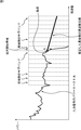
- the apparatus uses a low-frequency signal component after decoding as an input signal, from the power spectrum of the input signal, to a high-frequency power spectrum (hereinafter, appropriately referred to as a high-frequency envelope). , And a high frequency signal component having the high frequency envelope is generated from the low frequency signal component.
- FIG. 1 shows an example of a decoded low frequency power spectrum as an input signal and an estimated high frequency envelope.
- the vertical axis represents power in logarithm
- the horizontal axis represents frequency
- the apparatus determines the low band end band (hereinafter referred to as the expansion start band) of the high frequency signal component from the information (hereinafter referred to as side information) such as the type of the encoding method relating to the input signal, the sampling rate, and the bit rate. ).
- the apparatus divides the input signal as a low-frequency signal component into a plurality of subband signals. For each group in the time direction, the power of each of a plurality of subband signals after division, that is, a plurality of subband signals lower than the expansion start band (hereinafter simply referred to as a low band side). Is obtained (hereinafter referred to as group power). As shown in FIG.
- the apparatus starts from a point where the average of the group powers of a plurality of subband signals on the low frequency side is the power and the frequency at the lower end of the expansion start band is the frequency. .
- the apparatus estimates a linear line having a predetermined slope passing through the starting point as a frequency envelope on the high frequency side (hereinafter simply referred to as the high frequency side) from the expansion start band.
- the position of the starting point in the power direction can be adjusted by the user.
- the apparatus generates each of a plurality of subband signals on the high frequency side from the signals of the plurality of subbands on the low frequency side so that the estimated frequency envelope on the high frequency side is obtained.
- the apparatus adds a plurality of high-frequency side subband signals generated to form a high-frequency signal component, and further adds and outputs a low-frequency signal component. As a result, the music signal after the expansion of the frequency band becomes closer to the original music signal. Therefore, it is possible to reproduce a music signal with higher sound quality.
- the above-described band expansion method of Patent Document 1 can expand the frequency band of a music signal after decoding of encoded data of various high-frequency deletion encoding methods and encoded data of various bit rates. It has the feature.
- the band expansion method of Patent Document 1 has room for improvement in that the estimated high frequency side frequency envelope is a linear line with a predetermined slope, that is, the shape of the frequency envelope is fixed. There is.
- the power spectrum of the music signal has various shapes, and depending on the type of the music signal, there are many cases where the frequency envelope deviates significantly from the high frequency side frequency envelope estimated by the band expansion method of Patent Document 1.
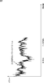
- FIG. 2 shows an example of the original power spectrum of an attack music signal (attack music signal) accompanied by a rapid change in time, for example, when the drum is struck once.
- attack music signal attack music signal
- FIG. 2 also shows the frequency envelope on the high frequency side estimated from the input signal using the low frequency signal component of the attack music signal as the input signal by the band expansion method of Patent Document 1. It is shown.
- the estimated frequency envelope on the high frequency side has a predetermined negative slope, and even if the power is adjusted to be close to the original power spectrum at the starting point, the original power is increased as the frequency is increased. The difference from the spectrum increases.
- the estimated high frequency side frequency envelope cannot accurately reproduce the original high frequency side frequency envelope.
- the intelligibility of the sound may be lost as compared with the original sound.
- the frequency envelope on the high frequency side is used as characteristic information of the high frequency signal component to be encoded. It is required to reproduce the frequency envelope on the band side with high accuracy.
- the present invention has been made in view of such a situation, and enables music signals to be reproduced with higher sound quality by expanding the frequency band.
- the frequency band expanding apparatus includes a signal dividing unit that divides an input signal into a plurality of subband signals, the plurality of subband signals divided by the signal dividing unit, and at least one of the input signals.
- a feature amount calculation unit that calculates a feature amount that represents a feature of the input signal using any one of the sub-bands higher than the input signal based on the feature amount calculated by the feature amount calculation unit
- a high-frequency sub-band power estimating unit that calculates an estimated value of a high-frequency sub-band power that is a signal power; the plurality of sub-band signals divided by the signal dividing unit; and the high-frequency sub-band power estimating unit.
- High-frequency signal component generating means for generating a high-frequency signal component based on the calculated estimated value of the high-frequency sub-band power, and the high-frequency signal component. Using the high frequency signal components generated by the generating means, to enlarge the frequency band of the input signal.
- the feature amount calculation means can calculate a low frequency sub-band power that is the power of the plurality of sub-band signals as the feature amount.
- the feature amount calculating means can calculate the temporal variation of the low frequency sub-band power, which is the power of the plurality of sub-band signals, as the feature amount.
- the feature amount calculating means can calculate the difference between the maximum value and the minimum value of the power in the predetermined frequency band of the input signal as the feature amount.
- the feature amount calculating means can calculate the time variation of the difference between the maximum value and the minimum value of power in a predetermined frequency band of the input signal as the feature amount.
- the feature quantity calculating means can calculate the power gradient of the input signal in a predetermined frequency band as the feature quantity.
- the feature amount calculation means can calculate the time variation of the power gradient in the predetermined frequency band of the input signal as the feature amount.
- the high frequency sub-band power estimation means can calculate the estimated value of the high frequency sub-band power based on the feature amount and a coefficient for each high frequency sub-band obtained by learning in advance. .
- the coefficient for each high frequency subband is a residual vector of the high frequency signal component calculated using the coefficients for each high frequency subband obtained by regression analysis using a plurality of teacher signals. Clustering is performed, and each cluster obtained by the clustering can be generated by performing regression analysis using the teacher signal belonging to the cluster.
- the residual vector is normalized by a variance value of each component of the plurality of residual vectors, and the normalized vectors can be clustered.
- the high frequency sub-band power estimating means calculates an estimated value of the high frequency sub-band power based on the feature amount and a coefficient and a constant for each high frequency sub-band,
- the residual vector is further calculated using a coefficient for each high-frequency subband obtained by regression analysis using the teacher signal belonging to the cluster, and the residual vector is clustered into a plurality of new clusters. It can be calculated from the centroid vector of the new cluster obtained in this way.
- the high frequency sub-band power estimating means records a coefficient for each high frequency sub-band and a pointer for specifying a coefficient for each high frequency sub-band in association with each other, and records the pointer and the constants.
- a plurality of sets may be recorded, and some of the plurality of pointers may include those indicating the same value.
- the high-frequency signal generation means can generate the high-frequency signal component from the low-frequency sub-band power that is the power of the plurality of sub-band signals and the estimated value of the high-frequency sub-band power.
- the frequency band expansion method includes a signal division step of dividing an input signal into a plurality of subband signals, the plurality of subband signals divided by the processing of the signal division step, and the input signal.
- a feature amount calculating step that calculates a feature amount that represents the feature of the input signal using at least one of the input signal, and a feature amount that is higher than the input signal based on the feature amount calculated by the processing of the feature amount calculating step.
- a high-frequency sub-band power estimation step for calculating an estimated value of the high-frequency sub-band power that is the power of the local sub-band signal, the plurality of sub-band signals divided by the processing of the signal division step, and the high frequency band Based on the estimated value of the high frequency sub-band power calculated by the processing of the sub-band power estimation step, the high frequency signal component is And a higher-band signal component generating step of forming, by using the high frequency signal components generated by the processing of the high frequency signal component generating step, expanding the frequency band of the input signal.
- a program includes a signal division step of dividing an input signal into a plurality of subband signals, and at least one of the plurality of subband signals divided by the processing of the signal division step and the input signal. Or a feature amount calculating step for calculating a feature amount representing a feature of the input signal, and a sub-range higher than the input signal based on the feature amount calculated by the processing of the feature amount calculating step.
- a high-frequency sub-band power estimation step for calculating an estimation value of a high-frequency sub-band power that is a power of the band signal, the plurality of sub-band signals divided by the processing of the signal division step, and the high-frequency sub-band power Based on the estimated value of the high frequency sub-band power calculated by the process of the estimation step, a high frequency signal component is generated And a band signal component generating step, by using the high frequency signal components generated by the processing of the high frequency signal component generating step to execute the processing for enlarging the frequency band of the input signal to the computer.
- an input signal is divided into a plurality of subband signals, and at least one of the divided subband signals and the input signal is used to represent a feature amount of the input signal.
- an estimated value of the high frequency sub-band power which is the power of the high frequency sub-band signal from the input signal, is calculated, and a plurality of divided sub-band signals are calculated.
- the high-frequency signal component is generated based on the estimated value of the high-frequency sub-band power, and the frequency band of the input signal is expanded using the generated high-frequency signal component.
- the encoding device divides an input signal into a plurality of subbands, and includes a low frequency subband signal composed of a plurality of low frequency subbands and a plurality of high frequency subbands.
- Subband dividing means for generating a high-frequency subband signal composed of bands, and the input using at least one of the low-frequency subband signal and the input signal generated by the subband dividing means
- a feature amount calculating means for calculating a feature amount representing a feature of the signal, and a pseudo high frequency sub-band which is a pseudo power of the high frequency sub-band signal based on the feature amount calculated by the feature amount calculating means.
- a high frequency that is the power of the high frequency sub-band signal from the high frequency sub-band signal generated by the pseudo high frequency sub-band power calculating means for calculating power and the sub-band dividing means A pseudo high band sub-band power difference calculation that calculates a sub-band power difference that is a difference from the pseudo high band sub-band power calculated by the pseudo high band sub-band power calculating unit.
- a high frequency encoding means for encoding the pseudo high frequency sub-band power difference calculated by the pseudo high frequency sub-band power difference calculating means and generating high frequency encoded data, and a low frequency of the input signal A low-frequency encoding means for encoding a low-frequency signal, and generating low-frequency encoded data, and the low-frequency encoded data generated by the low-frequency encoding means and the high-frequency encoding means
- multiplexing means for multiplexing the generated high frequency encoded data to obtain an output code string.
- the encoding device further includes low frequency decoding means for decoding the low frequency encoded data generated by the low frequency encoding means and generating a low frequency signal, and the subband dividing means includes the The low frequency subband signal can be generated from the low frequency signal generated by the low frequency decoding means.
- the high frequency encoding means calculates a similarity between the pseudo high frequency sub-band power difference and a representative vector or a representative value in a plurality of preset pseudo high frequency sub-band power difference spaces. An index corresponding to the maximum representative vector or representative value can be generated as the high frequency encoded data.
- the pseudo high frequency sub-band power difference calculating means includes, for each of a plurality of coefficients for calculating the pseudo high frequency sub-band power, the pseudo high frequency sub-band power and the high frequency sub-band power of each sub band.
- the high-frequency encoding means can generate an index indicating the coefficient of the evaluation value with the highest evaluation as the high-frequency encoded data.
- the pseudo high band sub-band power difference calculating means includes a sum of squares of the pseudo high band sub-band power difference of each sub band, a maximum absolute value of the pseudo high band sub-band power difference of the sub band, or each The evaluation value can be calculated based on at least one of the average values of the pseudo high frequency subband power differences of the subbands.
- the pseudo high band sub-band power difference calculating unit can calculate the evaluation value based on the difference of the pseudo high band sub-band power of different frames.
- the pseudo high frequency sub-band power difference calculating means uses the pseudo high frequency sub-band power difference multiplied by a weight that is a weight for each sub-band and becomes larger as the sub-band on the low frequency side. An evaluation value can be calculated.
- the pseudo high band sub-band power difference calculation means calculates the pseudo high band sub-band power difference multiplied by a weight for each sub-band, the weight being larger for the sub-band having a higher high band sub-band power.
- the evaluation value can be calculated.
- the encoding method divides an input signal into a plurality of subbands, and includes a low frequency subband signal composed of a plurality of low frequency subbands and a plurality of high frequency subbands.
- a subband splitting step for generating a highband subband signal composed of bands, and at least one of the lowband subband signal and the input signal generated by the processing of the subband splitting step,
- a feature amount calculating step for calculating a feature amount representing a feature of the input signal, and a pseudo-power that is a pseudo power of the high frequency subband signal based on the feature amount calculated by the processing of the feature amount calculating step
- From the pseudo high frequency sub-band power calculation step for calculating the high frequency sub-band power and the high frequency sub-band signal generated by the processing of the sub-band division step A high-frequency sub-band power that is the power of the high-frequency sub-band signal is calculated, and a pseudo high-frequency sub-band that is a difference from the pseudo high-frequency sub-band power calculated
- the program according to the second aspect of the present invention divides an input signal into a plurality of subbands, and includes a low frequency subband signal composed of a plurality of low frequency subbands and a plurality of high frequency subbands.
- a subband division step for generating a configured highband subband signal, and the input using at least one of the lowband subband signal and the input signal generated by the processing of the subband division step A feature amount calculating step for calculating a feature amount representing a feature of the signal, and a pseudo high frequency which is a pseudo power of the high frequency sub-band signal based on the feature amount calculated by the processing of the feature amount calculating step From the pseudo high frequency sub-band power calculation step for calculating the sub-band power and the high frequency sub-band signal generated by the processing of the sub-band division step A high-frequency sub-band power that is the power of the high-frequency sub-band signal is calculated, and a pseudo high-frequency sub-band that is a difference from the pseudo high-frequency sub-band power calculated by the
- the input signal is divided into a plurality of subbands, and is composed of a low frequency subband signal composed of a plurality of low frequency subbands and a plurality of high frequency subbands.
- a high-frequency sub-band signal is generated, and at least one of the generated low-frequency sub-band signal and the input signal is used to calculate a feature value that represents the feature of the input signal.
- the pseudo high band sub-band power that is the pseudo power of the high band sub-band signal is calculated, and the high band sub-band power that is the power of the high band sub-band signal is calculated from the generated high band sub-band signal.
- the calculated pseudo high frequency sub-band power difference which is a difference from the calculated pseudo high frequency sub-band power, is calculated, the calculated pseudo high frequency sub-band power difference is encoded, and the high frequency encoded data is
- the low frequency signal which is a low frequency signal of the input signal, is encoded, low frequency encoded data is generated, and the generated low frequency encoded data and the high frequency code generated by the high frequency encoding means And the encoded data are multiplexed to obtain an output code string.
- a decoding device includes a demultiplexing unit that demultiplexes input encoded data into at least lowband encoded data and an index, and decodes the lowband encoded data.
- a low-frequency decoding means for generating a low-frequency signal, and a sub-band dividing means for dividing the band of the low-frequency signal into a plurality of low-frequency sub-bands and generating a low-frequency sub-band signal for each low-frequency sub-band
- And generating means for generating the high frequency signal based on the index and the low frequency sub-band signal.
- the index is obtained based on the input signal before encoding and the high-frequency signal estimated from the input signal in an apparatus that encodes the input signal and outputs the encoded data. be able to.
- the index can be uncoded.
- the index may be information indicating an estimation coefficient used for generating the high frequency signal.
- the generation means can generate the high frequency signal based on the estimation coefficient indicated by the index among a plurality of the estimation coefficients.
- the generation means includes a feature quantity calculation means for calculating a feature quantity representing a feature of the encoded data using at least one of the low-frequency subband signal and the low-frequency signal; and A high frequency band for calculating a high frequency sub-band power of a high frequency sub-band signal of the high frequency sub-band for each of a plurality of high frequency sub-bands constituting the band by an operation using the feature amount and the estimation coefficient.
- Subband power calculating means, highband signal generating means for generating the highband signal based on the highband subband power and the lowband subband signal can be provided.
- the high frequency sub-band power calculating means linearly combines a plurality of the feature quantities using the estimation coefficient prepared for each high frequency sub-band, so that the high frequency sub-band power is calculated. Band power can be calculated.
- the feature amount calculation means can calculate the low frequency sub-band power of the low frequency sub-band signal for each low frequency sub-band as the feature value.
- the index is, among the plurality of estimation coefficients, the high-frequency subband power obtained from the high-frequency signal of the input signal before encoding, and the high-frequency subband power generated based on the estimation coefficient
- the information indicating the estimation coefficient for obtaining the high frequency sub-band power closest to the high frequency sub-band power obtained from the high frequency signal of the input signal before encoding is used. it can.
- the index is determined based on the high frequency subband power obtained from the high frequency signal of the input signal before encoding, which is obtained for each high frequency subband, and the high coefficient generated based on the estimation coefficient. It can be information indicating the estimation coefficient that minimizes the sum of squares of the difference from the local subband power.
- the encoded data includes a difference between the high frequency subband power obtained from the high frequency signal of the input signal before encoding and the high frequency subband power generated based on the estimation coefficient.
- the difference information shown can be further included.
- the difference information can be encoded.
- the high frequency sub-band power calculating means includes the difference indicated by the difference information included in the encoded data in the high frequency sub-band power obtained by the calculation using the feature amount and the estimation coefficient. And the high-frequency signal generating means can generate the high-frequency signal based on the high-frequency sub-band power added with the difference and the low-frequency sub-band signal.
- the estimation coefficient can be obtained by regression analysis using the least square method with the feature quantity as an explanatory variable and the high frequency sub-band power as an explanatory variable.
- the index includes, as an element, a difference between the high frequency sub-band power obtained from the high frequency signal of the input signal before encoding and the high frequency sub-band power generated based on the estimation coefficient, It can be information indicating a difference vector composed of the difference for each high frequency subband, and is obtained in advance for each of the estimation coefficients, in the feature space of the difference having the difference of each of the high frequency subbands as an element A distance between a representative vector or a representative value and the difference vector indicated by the index is obtained, and the representative vector or the estimation coefficient of the representative value that has the shortest distance among the plurality of estimation coefficients is set to the high value.
- Coefficient output means for supplying to the region subband power calculating means can be further provided.
- the index is a result of comparison between the high-frequency signal of the input signal before encoding and the high-frequency signal generated based on the estimation coefficient among the plurality of estimation coefficients, and the input before encoding. It can be information indicating the estimation coefficient from which the high frequency signal closest to the high frequency signal is obtained.
- the estimation coefficient can be obtained by regression analysis.
- the generation means can generate the high frequency signal based on information obtained by decoding the encoded index.
- the index can be entropy encoded.
- a decoding method or program includes a demultiplexing step of demultiplexing input encoded data into at least lowband encoded data and an index, and the lowband encoded data
- a low-band decoding step for decoding and generating a low-frequency signal
- a sub-band that divides a band of the low-frequency signal into a plurality of low-frequency sub-bands and generates a low-frequency sub-band signal for each low-frequency sub-band A dividing step
- the input encoded data is demultiplexed into at least low frequency encoded data and an index, and the low frequency encoded data is decoded to generate a low frequency signal.
- a band of the low-frequency signal is divided into a plurality of low-frequency sub-bands, a low-frequency sub-band signal for each low-frequency sub-band is generated, based on the index and the low-frequency sub-band signal, The high frequency signal is generated.
- the decoding apparatus demultiplexes input encoded data into low band encoded data and an index for obtaining an estimation coefficient used for generating a high band signal.
- a low frequency decoding means for decoding the low frequency encoded data to generate a low frequency signal, a band of the low frequency signal is divided into a plurality of low frequency subbands, and A feature amount calculation for calculating a feature amount representing a feature of the encoded data by using a sub-band dividing unit that generates a low-frequency sub-band signal and at least one of the low-frequency sub-band signal and the low-frequency signal.
- a high frequency sub-band power calculating means for calculating a high frequency sub-band power of the high frequency sub-band signal of the high frequency sub-band by calculating a sum of the feature quantities multiplied by the estimation coefficient; and the high frequency sub-band High-frequency signal generating means for generating the high-frequency signal using power and the low-frequency sub-band signal.
- the feature amount calculation means can calculate the low frequency sub-band power of the low frequency sub-band signal as the feature value for each low frequency sub-band.
- the index is a difference between the high band sub-band power obtained from the true value of the high band signal and the high band sub-band power generated using the estimation coefficient among the plurality of estimation coefficients. And it can be set as the information for obtaining the said estimation coefficient from which the square sum of the difference calculated
- the index further includes difference information indicating a difference between the high frequency sub-band power obtained from the true value and the high frequency sub-band power generated using the estimation coefficient
- the high frequency sub-band power calculating means adds the difference indicated by the difference information included in the index to the high frequency sub-band power obtained by calculating the sum of the feature quantities multiplied by the estimation coefficient.
- the high frequency signal generating means uses the high frequency sub-band power obtained by adding the difference by the high frequency sub-band power calculating means and the low frequency sub-band signal, and uses the high frequency sub-band signal. A signal can be generated.
- the index can be information indicating the estimation coefficient.
- the index is information obtained by entropy-encoding information indicating the estimation coefficient
- the high frequency sub-band power calculation means uses the estimation coefficient indicated by the information obtained by decoding the index. By using this, the high frequency sub-band power can be calculated.
- the plurality of estimation coefficients may be obtained in advance by regression analysis using a least square method with the feature quantity as an explanatory variable and the high frequency sub-band power as an explanatory variable.
- the index includes, as an element, a difference between the high frequency sub-band power obtained from the true value of the high frequency signal and the high frequency sub-band power generated using the estimation coefficient, and the high frequency sub-band A representative vector or representative value in the feature space of the difference, which is obtained in advance for each of the estimation coefficients, and includes the difference of each high-frequency subband, The distance from the difference vector indicated by the index is obtained, and the representative vector or the estimation coefficient of the representative value that has the shortest distance among the plurality of estimation coefficients is supplied to the high frequency subband power calculation means.
- Coefficient output means may be further provided.
- the decoding method or program according to the fourth aspect of the present invention is a non-multiplexing method that demultiplexes input encoded data into low frequency encoded data and an index for obtaining an estimation coefficient used for generating a high frequency signal.
- a feature for calculating a feature amount representing a feature of the encoded data by using a subband division step for generating a low-frequency subband signal for each, and at least one of the low-frequency subband signal and the low-frequency signal
- a quantity calculating step, and each of a plurality of high-frequency subbands constituting a band of the high-frequency signal is specified by the index among the plurality of estimation coefficients prepared in advance.
- a high frequency subband power for calculating a high frequency subband power of the high frequency subband signal of the high frequency subband is obtained by multiplying the characteristic value by a constant coefficient and obtaining a sum of the feature values multiplied by the estimation coefficient.
- the input encoded data is demultiplexed into low frequency encoded data and an index for obtaining an estimation coefficient used for generating a high frequency signal, and the low frequency code
- the low frequency signal is generated, a band of the low frequency signal is divided into a plurality of low frequency subbands, a low frequency subband signal for each low frequency subband is generated, and the low frequency signal is generated.
- a feature amount representing the characteristic of the encoded data is calculated, and each of the plurality of high-frequency sub-bands constituting the band of the high-frequency signal, Of the plurality of estimation coefficients prepared in advance, the estimation coefficient specified by the index is multiplied by the feature quantity, and the sum of the feature quantity multiplied by the estimation coefficient is obtained, thereby obtaining the high frequency band High frequency sub-band power of the high frequency sub-band signal subband is calculated, and the high frequency sub-band power, the using the low-frequency subband signal, the high frequency signal is generated.
- the music signal can be reproduced with higher sound quality by expanding the frequency band.
- FIG. 3 It is a figure which shows an example of the low frequency power spectrum after decoding as an input signal, and the estimated high frequency envelope. It is a figure which shows an example of the original power spectrum of the attack music signal accompanied with a rapid change in time. It is a block diagram which shows the functional structural example of the frequency band expansion apparatus in the 1st Embodiment of this invention. 4 is a flowchart for explaining an example of frequency band expansion processing by the frequency band expansion device of FIG. 3. It is a figure which shows the arrangement
- First embodiment when the present invention is applied to a frequency band expansion device
- Second embodiment when the present invention is applied to an encoding device and a decoding device
- Third embodiment when a coefficient index is included in high frequency encoded data
- Fourth embodiment when a coefficient index and a pseudo high band sub-band power difference are included in high band encoded data
- Fifth embodiment when a coefficient index is selected using an evaluation value
- Sixth embodiment when some of the coefficients are shared
- a process of expanding a frequency band (hereinafter referred to as a frequency band expansion process) with respect to a low-frequency signal component after decoding obtained by decoding encoded data using a high-frequency deletion encoding method. Is called).
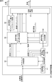
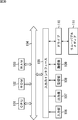
- FIG. 3 shows a functional configuration example of a frequency band expansion apparatus to which the present invention is applied.
- the frequency band expansion device 10 uses the decoded low-frequency signal component as an input signal, performs frequency band expansion processing on the input signal, and outputs the resulting signal after frequency band expansion processing as an output signal To do.
- the frequency band expansion apparatus 10 includes a low-pass filter 11, a delay circuit 12, a band-pass filter 13, a feature amount calculation circuit 14, a high-frequency sub-band power estimation circuit 15, a high-frequency signal generation circuit 16, a high-pass filter 17, And a signal adder 18.
- the low-pass filter 11 filters the input signal with a predetermined cutoff frequency, and supplies a low-frequency signal component, which is a low-frequency signal component, to the delay circuit 12 as a filtered signal.
- the delay circuit 12 delays the low-frequency signal component by a certain delay time in order to synchronize when adding a low-frequency signal component from the low-pass filter 11 and a high-frequency signal component described later. This is supplied to the adder 18.
- the band pass filter 13 is composed of band pass filters 13-1 to 13-N each having a different pass band.
- the band pass filter 13-i (1 ⁇ i ⁇ N) passes a signal in a predetermined pass band among the input signals, and as one of the plurality of subband signals, the feature amount calculation circuit 14 and the high frequency band
- the signal generation circuit 16 is supplied.
- the feature amount calculation circuit 14 calculates one or a plurality of feature amounts using at least one of the plurality of subband signals from the band pass filter 13 and the input signal, and a high frequency subband power estimation circuit. 15 is supplied.
- the feature amount is information representing the feature of the input signal as a signal.
- the high frequency sub-band power estimation circuit 15 calculates the high frequency sub-band power estimation value, which is the power of the high frequency sub-band signal, based on the one or more feature values from the feature value calculation circuit 14. Calculation is performed for each band, and these are supplied to the high frequency signal generation circuit 16.
- the high-frequency signal generation circuit 16 generates a high-frequency signal based on the plurality of sub-band signals from the band-pass filter 13 and the plurality of high-frequency sub-band power estimation values from the high-frequency sub-band power estimation circuit 15.
- a high-frequency signal component that is a component is generated and supplied to the high-pass filter 17.
- the high-pass filter 17 filters the high-frequency signal component from the high-frequency signal generation circuit 16 with a cutoff frequency corresponding to the cutoff frequency in the low-pass filter 11 and supplies the filtered signal to the signal adder 18.
- the signal adder 18 adds the low-frequency signal component from the delay circuit 12 and the high-frequency signal component from the high-pass filter 17 and outputs the result as an output signal.
- the bandpass filter 13 is applied to acquire the subband signal.
- the present invention is not limited to this.
- a band division filter as described in Patent Document 1 is used. You may make it apply.
- the signal adder 18 is applied to synthesize the subband signal.
- the present invention is not limited to this.
- band synthesis as described in Patent Document 1 is used.
- a filter may be applied.
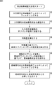
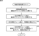
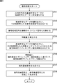
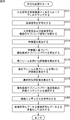
- step S1 the low-pass filter 11 filters the input signal with a predetermined cutoff frequency, and supplies the low-frequency signal component as the filtered signal to the delay circuit 12.
- the low-pass filter 11 can set an arbitrary frequency as the cutoff frequency, but in the present embodiment, the predetermined band is set as an expansion start band described later, and corresponds to the frequency at the lower end of the expansion start band. Thus, the cutoff frequency is set. Therefore, the low-pass filter 11 supplies a low-frequency signal component, which is a signal component lower than the expansion start band, to the delay circuit 12 as a filtered signal.
- the low-pass filter 11 can set an optimum frequency as a cut-off frequency in accordance with a high-frequency deletion encoding method of the input signal and an encoding parameter such as a bit rate.
- an encoding parameter such as a bit rate.
- side information adopted in the band expansion method of Patent Document 1 can be used.
- step S2 the delay circuit 12 delays the low-frequency signal component from the low-pass filter 11 by a predetermined delay time and supplies the delayed signal to the signal adder 18.
- step S3 the bandpass filter 13 (bandpass filters 13-1 to 13-N) divides the input signal into a plurality of subband signals, and each of the divided subband signals is converted into a feature amount calculation circuit. 14 and the high-frequency signal generation circuit 16. The details of the process of dividing the input signal by the band pass filter 13 will be described later.
- step S4 the feature amount calculation circuit 14 calculates one or a plurality of feature amounts using at least one of the plurality of subband signals from the bandpass filter 13 and the input signal. This is supplied to the band power estimation circuit 15. Details of the feature amount calculation processing by the feature amount calculation circuit 14 will be described later.
- step S5 the high frequency sub-band power estimation circuit 15 calculates a plurality of high frequency sub-band power estimates based on one or more feature values from the feature value calculation circuit 14, and generates a high frequency signal. Supply to circuit 16. The details of the processing for calculating the estimated value of the high frequency sub-band power by the high frequency sub-band power estimation circuit 15 will be described later.
- step S6 the high frequency signal generation circuit 16 is based on the plurality of subband signals from the bandpass filter 13 and the plurality of high frequency subband power estimation values from the high frequency subband power estimation circuit 15.
- a high-frequency signal component is generated and supplied to the high-pass filter 17.
- the high-frequency signal component here is a signal component higher than the expansion start band. Details of the processing of generating the high frequency signal component by the high frequency signal generation circuit 16 will be described later.
- step S7 the high-pass filter 17 filters the high-frequency signal component from the high-frequency signal generation circuit 16 to remove noise such as the aliasing component to the low frequency included in the high-frequency signal component.
- the high frequency signal component is supplied to the signal adder 18.
- step S8 the signal adder 18 adds the low-frequency signal component from the delay circuit 12 and the high-frequency signal component from the high-pass filter 17 and outputs the result as an output signal.
- the frequency band can be expanded with respect to the low-frequency signal component after decoding.
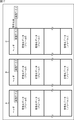
- one of 16 subbands obtained by dividing the Nyquist frequency of the input signal into 16 equal parts is set as an expansion start band, and a lower band than the expansion start band of these 16 subbands.
- Each of the four subbands is set as a passband of the bandpass filters 13-1 to 13-4.
- FIG. 5 shows the arrangement on the frequency axis of each pass band of the band pass filters 13-1 to 13-4.
- the index of the first subband from the high frequency band (subband) lower than the expansion start band is sb
- the index of the second subband is sb-1
- I Assuming that the index of the second subband is sb- (I-1), each of the bandpass filters 13-1 to 13-4 has an index of sb to sb-3 among the subbands lower than the expansion start band.
- Each subband is assigned as a passband.
- each of the passbands of the bandpass filters 13-1 to 13-4 is a predetermined 4 out of 16 subbands obtained by dividing the Nyquist frequency of the input signal into 16 equal parts.
- the present invention is not limited to this, and each of the predetermined four of 256 subbands obtained by dividing the Nyquist frequency of the input signal into 256 equal parts may be used. . Further, the bandwidths of the bandpass filters 13-1 to 13-4 may be different from each other.
- the feature amount calculation circuit 14 uses the at least one of the plurality of subband signals from the bandpass filter 13 and the input signal, and the high frequency subband power estimation circuit 15 estimates the high frequency subband power. One or a plurality of feature amounts used to calculate the value are calculated.
- the feature quantity calculation circuit 14 determines the power of the subband signal (subband power (hereinafter referred to as low band subband power) from each of the four subband signals from the bandpass filter 13 for each subband. )) Is calculated as a feature amount and supplied to the high frequency sub-band power estimation circuit 15.
- subband power hereinafter referred to as low band subband power
- the feature amount calculation circuit 14 uses the low-frequency subband power power (ib, J) in a predetermined time frame J from the four subband signals x (ib, n) supplied from the bandpass filter 13. Is obtained by the following equation (1).
- ib represents a subband index
- n represents a discrete time index. It is assumed that the number of samples in one frame is FSIZE and the power is expressed in decibels.
- the low frequency sub-band power (ib, J) obtained by the feature value calculation circuit 14 is supplied to the high frequency sub-band power estimation circuit 15 as a feature value.
- the high frequency subband power estimation circuit 15 tries to expand after the subband (enlargement start band) whose index is sb + 1. An estimated value of the subband power (high frequency subband power) of the band (frequency expansion band) is calculated.
- the high frequency subband power estimation circuit 15 sets (eb ⁇ sb) subband powers for the subbands whose indexes are sb + 1 to eb, where eb is the index of the highest frequency band in the frequency expansion band.
- the estimated value power est (ib, J) of the subband power whose index is ib in the frequency expansion band is obtained by using the four subband powers power (ib, j) supplied from the feature amount calculation circuit 14. For example, it is represented by the following formula (2).
- the coefficients A ib (kb) and B ib are coefficients having different values for each subband ib.
- the coefficients A ib (kb) and B ib are coefficients that are appropriately set so as to obtain suitable values for various input signals. Further, the coefficients A ib (kb) and B ib are also changed to optimum values by changing the subband sb. Derivation of the coefficients A ib (kb) and B ib will be described later.
- the estimated value of the high frequency sub-band power is calculated by the linear linear combination using the power of each of the plurality of sub-band signals from the band pass filter 13, but is not limited to this.
- the calculation may be performed using a linear combination of a plurality of low-frequency subband powers of several frames before and after the time frame J, or may be calculated using a non-linear function.
- the estimated value of the high frequency sub-band power calculated by the high frequency sub-band power estimation circuit 15 is supplied to the high frequency signal generation circuit 16.
- the high-frequency signal generation circuit 16 calculates the low-frequency sub-band power power (ib, J) of each sub-band from the plurality of sub-band signals supplied from the band-pass filter 13 based on the above equation (1). calculate.
- the high-frequency signal generation circuit 16 includes a plurality of calculated low-frequency sub-band powers power (ib, J) and a high-frequency sub-band calculated by the high-frequency sub-band power estimation circuit 15 based on the above equation (2).
- the gain amount G (ib, J) is obtained by the following equation (3).
- sb map (ib) indicates the index of the mapping source subband when subband ib is the mapping target subband, and is represented by the following equation (4). .
- INT (a) is a function that truncates the value a after the decimal point.
- the high-frequency signal generation circuit 16 multiplies the output of the bandpass filter 13 by the gain amount G (ib, J) obtained by the equation (3) using the following equation (5), thereby adjusting the gain.
- the subsequent subband signal x2 (ib, n) is calculated.
- the high frequency signal generation circuit 16 corresponds to the frequency at the upper end of the subband with the index sb from the frequency corresponding to the frequency at the lower end of the subband with the index sb-3 by the following equation (6).
- the gain-adjusted subband signal x3 (ib, n) is calculated from the gain-adjusted subband signal x2 (ib, n).
- ⁇ represents the circumference ratio. This equation (6) means that the subband signal x2 (ib, n) after gain adjustment is shifted to the frequency on the high band side by 4 bands.
- the high-frequency signal generation circuit 16 calculates the high-frequency signal component x high (n) from the gain-adjusted subband signal x3 (ib, n) shifted to the high frequency side by the following equation (7). To do.
- the low-frequency subband power calculated from a plurality of subband signals is used as a feature amount. Based on the coefficient set appropriately, the estimated value of the high frequency sub-band power is calculated, and the high frequency signal component is generated adaptively from the estimated value of the low frequency sub-band power and the high frequency sub-band power. Therefore, the subband power in the frequency expansion band can be estimated with high accuracy, and the music signal can be reproduced with higher sound quality.
- the feature amount calculation circuit 14 calculates only the low frequency subband power calculated from a plurality of subband signals as the feature amount. In this case, depending on the type of the input signal, the frequency expansion is performed. In some cases, the subband power of the band cannot be estimated with high accuracy.
- the feature amount calculation circuit 14 calculates a feature amount having a strong correlation with the output of the sub-band power in the frequency expansion band (the shape of the high-frequency power spectrum), so that the high-frequency sub-band power estimation circuit. 15 can be estimated with higher accuracy.
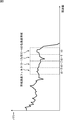
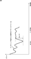
- FIG. 6 shows an example of a frequency characteristic of a vocal section in which a vocal occupies most of an input signal, and estimates a high band subband power by calculating only a low band subband power as a feature amount. The high-frequency power spectrum obtained by doing this is shown.
- the estimated high frequency power spectrum is often located above the high frequency power spectrum of the original signal. Since the sense of incongruity of human singing voices is easily perceived by human ears, it is necessary to estimate the high frequency subband power particularly accurately in the vocal section.
- the degree of dent in the frequency domain from 4.9 kHz to 11.025 kHz is applied as the feature quantity used for estimating the high frequency sub-band power in the vocal section.
- the feature amount indicating the degree of the dent is hereinafter referred to as a dip.
- a 2048-point FFT Fast Fourier Transform
- a 2048 sample section included in the range of several frames before and after the time frame J in the input signal, and a coefficient on the frequency axis is calculated.
- a power spectrum is obtained by performing db conversion on the absolute value of each calculated coefficient.
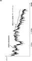
- FIG. 7 shows an example of the power spectrum obtained as described above.
- a liftering process is performed so as to remove a component of 1.3 kHz or less.
- each dimension of the power spectrum is regarded as a time series, and the filtering process is performed by applying a low-pass filter, whereby the fine component of the spectrum peak can be smoothed.
- FIG. 8 shows an example of the power spectrum of the input signal after liftering.
- the difference between the minimum value and the maximum value of the power spectrum included in the range corresponding to 4.9 kHz to 11.025 kHz is defined as dip dip (J).
- dip dip (J) is not limited to the above-described method, and may be another method.
- the power spectrum on the high frequency side is often almost flat in the frequency characteristics of the attack period, which is a period in which an input music signal includes an attack music signal.
- the sub-band power in the frequency expansion band is estimated without using the feature value representing the time variation peculiar to the input signal including the attack interval. It is difficult to accurately estimate the sub-band power of a substantially flat frequency expansion band.
- the time fluctuation power d (J) of the low frequency sub-band power in a certain time frame J is obtained by the following equation (8), for example.
- the time variation power d (J) of the low frequency subband power is the sum of the four low frequency subband powers in the time frame J and the time frame (1 frame before the time frame J) J-1) represents the ratio to the sum of the four low-band subband powers. The larger this value, the greater the time variation of the power between frames. That is, the signal included in the time frame J is attacked. It is considered strong.
- the power spectrum in the attack section is right in the middle range. It is going up.
- the attack section often shows such frequency characteristics.
- the mid-range slope slope (J) in a certain time frame J is obtained by the following equation (9), for example.
- Equation (9) the coefficient w (ib) is a weighting coefficient adjusted to weight the high frequency subband power.
- slope (J) represents the ratio of the sum of the four low frequency subband powers weighted to the high frequency and the sum of the four low frequency subband powers. For example, if four low-frequency sub-band powers are the power for the mid-frequency sub-band, slope (J) has a large value when the mid-range power spectrum rises to the right, and when it falls to the right Take a small value.
- the slope time fluctuation slope d (J) expressed by the following equation (10) is used to estimate the high-frequency subband power of the attack section. You may make it be the feature-value used for.
- the time variation dip d (J) of the above-described dip dip (J) expressed by the following equation (11) is used as a feature amount used for estimating the high frequency sub-band power in the attack section. May be.
- the feature quantity having a strong correlation with the subband power in the frequency extension band is calculated.
- the subband power in the frequency extension band in the high frequency subband power estimation circuit 15 is estimated. Can be performed with higher accuracy.
- the example of calculating the feature quantity having a strong correlation with the subband power in the frequency expansion band has been described.
- the high frequency subband power is estimated using the feature quantity thus calculated. An example will be described.
- step S4 of the flowchart of FIG. 4 the feature amount calculation circuit 14 uses the low-frequency subband power and the dip as the feature amount for each subband from the four subband signals from the bandpass filter 13. Calculated and supplied to the high frequency sub-band power estimation circuit 15.
- step S5 the high frequency sub-band power estimation circuit 15 calculates an estimation value of the high frequency sub-band power based on the four low frequency sub-band powers and the dip from the feature amount calculation circuit 14.
- the high frequency subband power estimation circuit 15 performs, for example, the following conversion on the dip value.
- the high frequency sub-band power estimation circuit 15 calculates the sub-band power and the dip value of the highest frequency among the four low-frequency sub-band powers in advance for a large number of input signals, and averages each of them. And obtain the standard deviation.
- the average value of the subband power is power ave
- the standard deviation of the subband power is power std
- the average value of the dip is dip ave
- the standard deviation of the dip is dip std .
- the high frequency subband power estimation circuit 15 converts the dip value dip (J) using these values as shown in the following equation (12), and obtains the converted dip dip s (J).
- the high frequency subband power estimation circuit 15 changes the dip value dip (J) to a variable (dip) that is statistically equal to the mean and variance of the low frequency subband power.
- dip s (J) can be converted, and the range of values that can be taken by dip can be made substantially the same as the range of values that can be taken by subband power.
- the estimated value power est (ib, J) of the subband power whose index is ib in the frequency expansion band is four low band subband powers power (ib, J) from the feature quantity calculation circuit 14 and the formula ( Using the linear combination with dip dip s (J) shown in 12), for example, it is expressed by the following equation (13).
- the coefficients C ib (kb), D ib , and E ib are coefficients having different values for each subband ib.
- the coefficients C ib (kb), D ib , and E ib are coefficients that are appropriately set so that suitable values can be obtained for various input signals. Further, the coefficients C ib (kb), D ib , and E ib are also changed to optimum values by changing the subband sb. The derivation of the coefficients C ib (kb), D ib and E ib will be described later.
- the estimated value of the high frequency sub-band power is calculated by a linear linear combination, but is not limited to this, and for example, a linear combination of a plurality of feature quantities before and after the time frame J is obtained. It may be calculated using a non-linear function.
- the dip value peculiar to the vocal section is used as the feature amount for the estimation of the high frequency sub-band power, and compared with the case where only the low frequency sub-band power is the feature amount,
- This is a technique that improves the estimation accuracy of the high frequency sub-band power and uses only the low frequency sub-band power as a feature, and is generated when the high frequency power spectrum is estimated to be larger than the high frequency power spectrum of the original signal. Therefore, it is possible to reproduce a music signal with higher sound quality.
- the number of subband divisions is increased (for example, 16 times 256 divisions), the number of band divisions by the band-pass filter 13 is increased (for example, 16 times 64 times), and the low frequency subband calculated by the feature amount calculation circuit 14
- the number of powers for example, 64 times 16
- the amount of calculation increases by increasing the number of subband divisions, the number of band divisions, and the number of low-frequency subband powers.
- the method of estimating the high frequency subband power using the dip as a feature quantity does not increase the number of subband divisions. It is considered efficient in terms of quantity.
- the method for estimating the high frequency sub-band power using the dip and the low frequency sub-band power has been described.
- the feature amount used for the estimation of the high frequency sub-band power is not limited to this combination.
- One or more of the above-described feature quantities (low frequency sub-band power, dip, time variation of low frequency sub-band power, inclination, time variation of inclination, and time variation of dip) may be used. Good. Thereby, the accuracy can be further improved in the estimation of the high frequency sub-band power.
- the time fluctuation of the low frequency subband power, the time fluctuation of the slope, the time fluctuation of the slope, and the time fluctuation of the dip are parameters specific to the attack section, and by using these parameters as feature quantities, a high frequency in the attack section is obtained.
- the estimation accuracy of the regional subband power can be improved.
- the high frequency sub-band power can be estimated by the same method as described above.
- the coefficients C ib (kb), D ib , and E ib are obtained by calculating the coefficients C ib (kb), D ib , and E ib for various input signals in estimating the subband power in the frequency expansion band.
- a method is used in which learning is performed in advance using a wideband teacher signal (hereinafter referred to as a “broadband teacher signal”) and a decision is made based on the learning result.
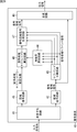
- FIG. 9 shows a functional configuration example of a coefficient learning apparatus that performs learning of the coefficients C ib (kb), D ib , and E ib .
- the wide band teacher signal input to the coefficient learning device 20 of FIG. 9 is encoded by the band-limited input signal input to the frequency band expansion device 10 of FIG. It is preferable that the signal is encoded by the same method as the encoding method applied at the time.
- the coefficient learning device 20 includes a band-pass filter 21, a high-frequency sub-band power calculation circuit 22, a feature amount calculation circuit 23, and a coefficient estimation circuit 24.
- the band pass filter 21 is composed of band pass filters 21-1 to 21- (K + N) each having a different pass band.
- the band-pass filter 21-i (1 ⁇ i ⁇ K + N) passes a signal in a predetermined pass band among the input signals, and as one of the plurality of sub-band signals, the high-frequency sub-band power calculation circuit 22 Alternatively, it is supplied to the feature amount calculation circuit 23.
- the bandpass filters 21-1 to 21- (K + N) the bandpass filters 21-1 to 21-K pass signals in a higher band than the expansion start band.
- the high frequency sub-band power calculation circuit 22 calculates the high frequency sub-band power for each sub-band for each of a certain time frame with respect to a plurality of high frequency sub-band signals from the band-pass filter 21, and the coefficient This is supplied to the estimation circuit 24.
- the feature quantity calculating circuit 23 is the feature quantity calculating circuit 14 of the frequency band expanding apparatus 10 of FIG. The same feature quantity as the feature quantity calculated by is calculated. That is, the feature quantity calculation circuit 23 calculates one or a plurality of feature quantities using at least one of the plurality of subband signals from the band pass filter 21 and the wideband teacher signal, and the coefficient estimation circuit 24. To supply.
- the coefficient estimation circuit 24 expands the frequency band of FIG. 3 based on the high frequency sub-band power from the high frequency sub-band power calculation circuit 22 and the feature value from the feature value calculation circuit 23 for each fixed time frame. A coefficient (coefficient data) used in the high frequency sub-band power estimation circuit 15 of the apparatus 10 is estimated.
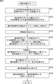
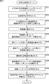
- the band pass filter 21 divides the input signal (broadband teacher signal) into (K + N) subband signals.
- the bandpass filters 21-1 to 21 -K supply a plurality of subband signals higher than the expansion start band to the highband subband power calculation circuit 22. Further, the band pass filters 21- (K + 1) to 21- (K + N) supply a plurality of subband signals lower than the expansion start band to the feature amount calculation circuit 23.
- step S12 the high-frequency sub-band power calculation circuit 22 applies a certain time frame to a plurality of high-frequency sub-band signals from the band-pass filter 21 (band-pass filters 21-1 to 21-K). Then, the high frequency sub-band power power (ib, J) for each sub-band is calculated. The high frequency sub-band power power (ib, J) is obtained by the above equation (1). The high frequency sub-band power calculation circuit 22 supplies the calculated high frequency sub-band power to the coefficient estimation circuit 24.
- step S13 the feature quantity calculation circuit 23 calculates a feature quantity for each time frame that is the same as a certain time frame in which the high band subband power is calculated by the high band subband power calculation circuit 22.
- the feature amount calculation circuit 14 of the frequency band expansion device 10 in FIG. 3 calculates four subband powers and dip in the low band as feature amounts, and the coefficient learning device 20 Similarly, the feature amount calculation circuit 23 will be described assuming that the four subband powers and dip in the low band are calculated.
- the feature amount calculation circuit 23 receives four pieces of input from the band pass filter 21 (band pass filters 21- (K + 1) to 21- (K + 4)) to the feature amount calculation circuit 14 of the frequency band expansion device 10.
- Four low-band sub-band powers are calculated using four sub-band signals each having the same band as the sub-band signal.
- the feature quantity calculation circuit 23 calculates a dip from the wideband teacher signal, and calculates the dip dip s (J) based on the above equation (12).
- the feature amount calculation circuit 23 supplies the calculated four low frequency subband powers and the dip dip s (J) to the coefficient estimation circuit 24 as feature amounts.
- the coefficient estimation circuit 24 supplies (eb-sb) high frequency sub-band powers and feature values (4) supplied from the high frequency sub-band power calculation circuit 22 and the feature value calculation circuit 23 in the same time frame.
- the coefficients C ib (kb), D ib , and E ib are estimated based on a number of combinations of the low frequency sub-band power and the dip dip s (J). For example, the coefficient estimation circuit 24 uses five feature values (four low frequency subband powers and dip s s (J)) as explanatory variables for one of the high frequency subbands.
- the coefficients C ib (kb), D ib , and E ib in Equation (13) are determined by performing regression analysis using the least square method with power (ib, J) of
- the estimation method of the coefficients C ib (kb), D ib , and E ib is not limited to the above method, and various general parameter identification methods may be applied.
- the coefficients A ib (kb) and B ib in the above equation (2) can also be obtained by the above-described coefficient learning method.
- each of the high band sub-band power estimation values is calculated by linear combination of the four low band sub-band powers and the dip.
- the coefficient learning process based on the above has been described.
- the method of estimating the high frequency sub-band power in the high frequency sub-band power estimation circuit 15 is not limited to the above-described example.
- the feature value calculation circuit 14 uses a feature value other than the dip (the low frequency sub-band power value).
- the high frequency sub-band power may be calculated by calculating one or more of time fluctuation, inclination, time fluctuation of inclination, and time fluctuation of dip), or a plurality of frames before and after time frame J.
- the coefficient estimation circuit 24 uses the feature amount, time frame, and function used when the high frequency sub-band power estimation circuit 15 of the frequency band expansion device 10 calculates the high frequency sub-band power. It is only necessary that the coefficients can be calculated (learned) under the same conditions as those described above.
- Second Embodiment> encoding processing and decoding processing in a high-frequency feature encoding method are performed by an encoding device and a decoding device.
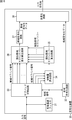
- FIG. 11 shows a functional configuration example of an encoding apparatus to which the present invention is applied.
- the encoding device 30 includes a low-pass filter 31, a low-frequency encoding circuit 32, a sub-band division circuit 33, a feature amount calculation circuit 34, a pseudo high-frequency sub-band power calculation circuit 35, and a pseudo high-frequency sub-band power difference calculation circuit. 36, a high frequency encoding circuit 37, a multiplexing circuit 38, and a low frequency decoding circuit 39.
- the low-pass filter 31 filters the input signal with a predetermined cutoff frequency, and a signal having a frequency lower than the cutoff frequency (hereinafter referred to as a low-frequency signal) is filtered as a filtered signal. This is supplied to the band dividing circuit 33 and the feature amount calculating circuit 34.
- the low-frequency encoding circuit 32 encodes the low-frequency signal from the low-pass filter 31 and supplies low-frequency encoded data obtained as a result to the multiplexing circuit 38 and the low-frequency decoding circuit 39.
- the subband division circuit 33 equally divides the input signal and the low-frequency signal from the low-pass filter 31 into a plurality of subband signals having a predetermined bandwidth, and the feature amount calculation circuit 34 or the pseudo high-frequency subband power
- the difference calculation circuit 36 is supplied. More specifically, the subband dividing circuit 33 supplies a plurality of subband signals (hereinafter referred to as lowband subband signals) obtained by receiving the lowband signal to the feature amount calculation circuit 34.
- the subband dividing circuit 33 is a subband signal higher than the cut-off frequency set by the low-pass filter 31 (hereinafter referred to as a high-frequency subband) among a plurality of subband signals obtained by using an input signal as an input. (Referred to as a signal) is supplied to the pseudo high band sub-band power difference calculation circuit 36.
- the feature quantity calculation circuit 34 uses at least one of a plurality of subband signals among the lowband subband signals from the subband division circuit 33 and the lowband signal from the lowpass filter 31. One or a plurality of feature amounts are calculated and supplied to the pseudo high band sub-band power calculation circuit 35.
- the pseudo high frequency sub-band power calculation circuit 35 generates pseudo high frequency sub-band power based on one or a plurality of feature values from the feature value calculation circuit 34 and supplies the pseudo high frequency sub-band power difference calculation circuit 36 to the pseudo high frequency sub-band power difference calculation circuit 36. Supply.
- the pseudo high frequency sub-band power difference calculation circuit 36 will be described later based on the high frequency sub-band signal from the sub-band division circuit 33 and the pseudo high frequency sub-band power from the pseudo high frequency sub-band power calculation circuit 35.
- the pseudo high frequency sub-band power difference is calculated and supplied to the high frequency encoding circuit 37.
- the high frequency encoding circuit 37 encodes the pseudo high frequency sub-band power difference from the pseudo high frequency sub-band power difference calculation circuit 36, and supplies the high frequency encoded data obtained as a result to the multiplexing circuit 38.
- the multiplexing circuit 38 multiplexes the low frequency encoded data from the low frequency encoding circuit 32 and the high frequency encoded data from the high frequency encoding circuit 37 and outputs the result as an output code string.
- the low-frequency decoding circuit 39 appropriately decodes the low-frequency encoded data from the low-frequency encoding circuit 32, and supplies the decoded data obtained as a result to the subband division circuit 33 and the feature amount calculation circuit 34.
- step S111 the low-pass filter 31 filters the input signal with a predetermined cutoff frequency, and the low-frequency signal as the filtered signal is converted into the low-frequency encoding circuit 32, the subband dividing circuit 33, and the feature amount calculation. Supply to circuit 34.
- step S112 the low-frequency encoding circuit 32 encodes the low-frequency signal from the low-pass filter 31, and supplies the low-frequency encoded data obtained as a result to the multiplexing circuit 38.
- an appropriate encoding method may be selected according to the encoding efficiency and the required circuit scale, and the present invention does not depend on this encoding method.
- the subband dividing circuit 33 equally divides the input signal and the low frequency signal into a plurality of subband signals having a predetermined bandwidth.
- the subband dividing circuit 33 supplies a low frequency subband signal obtained by using the low frequency signal as an input to the feature amount calculation circuit 34.
- the subband division circuit 33 outputs a high-frequency subband signal having a band higher than the band-limited frequency set by the low-pass filter 31 among the plurality of subband signals obtained by using the input signal as an input.
- the pseudo high band sub-band power difference calculation circuit 36 is supplied.
- step S ⁇ b> 114 the feature amount calculation circuit 34 at least one of a plurality of subband signals among the lowband subband signals from the subband division circuit 33 and the lowband signal from the lowpass filter 31. Is used to calculate one or a plurality of feature quantities and supply them to the pseudo high band sub-band power calculation circuit 35.
- 11 has basically the same configuration and function as the feature amount calculation circuit 14 in FIG. 3, and the process in step S114 is the process in step S4 in the flowchart in FIG. Since this is basically the same, detailed description thereof will be omitted.
- step S115 the pseudo high frequency sub-band power calculation circuit 35 generates pseudo high frequency sub-band power based on one or more feature values from the feature value calculation circuit 34, and generates a pseudo high frequency sub-band power difference. This is supplied to the calculation circuit 36.
- the pseudo high band sub-band power calculation circuit 35 in FIG. 11 has basically the same configuration and function as the high band sub-band power estimation circuit 15 in FIG. Since this process is basically the same as the process in step S5 of the flowchart of FIG.
- step S116 the pseudo high frequency sub-band power difference calculation circuit 36 is based on the high frequency sub-band signal from the sub-band division circuit 33 and the pseudo high frequency sub-band power from the pseudo high frequency sub-band power calculation circuit 35. Then, the pseudo high frequency sub-band power difference is calculated and supplied to the high frequency encoding circuit 37.
- the pseudo high frequency sub-band power difference calculation circuit 36 applies the (high frequency) sub-band power power (ib,) in a certain time frame J to the high frequency sub-band signal from the sub-band division circuit 33. J) is calculated.
- all subbands of the low frequency subband signal and the high frequency subband signal are identified using the index ib.
- a subband power calculation method a method similar to that in the first embodiment, that is, a method using Expression (1) can be applied.
- the pseudo high band sub-band power difference calculation circuit 36 includes the high band sub-band power power (ib, J) and the pseudo high band sub-band power from the pseudo high band sub-band power calculation circuit 35 in the time frame J. Find the difference (pseudo high band sub-band power difference) power diff (ib, J) from lh (ib, J). The pseudo high frequency sub-band power difference power diff (ib, J) is obtained by the following equation (14).
- the index sb + 1 represents the index of the lowest subband in the high frequency subband signal.
- the index eb represents the index of the highest frequency subband encoded in the high frequency subband signal.
- the pseudo high band sub-band power difference calculated by the pseudo high band sub-band power difference calculating circuit 36 is supplied to the high band encoding circuit 37.
- step S117 the high frequency encoding circuit 37 encodes the pseudo high frequency sub-band power difference from the pseudo high frequency sub-band power difference calculation circuit 36, and the resulting high frequency encoded data is sent to the multiplexing circuit 38. Supply.
- the high frequency encoding circuit 37 vectorizes the pseudo high frequency sub-band power difference from the pseudo high frequency sub-band power difference calculation circuit 36 (hereinafter referred to as a pseudo high frequency sub-band power difference vector). Which of the plurality of clusters in the preset characteristic space of the pseudo high band sub-band power difference belongs to which cluster is designated.
- the pseudo high band sub-band power difference vector in a certain time frame J has the value of the pseudo high band sub-band power difference power diff (ib, J) for each index ib as each element of the vector (eb-sb ) Dimensional vector.
- the feature space of the pseudo high frequency subband power difference is an (eb-sb) -dimensional space.
- the high frequency encoding circuit 37 measures the distance between each representative vector of a plurality of clusters set in advance and the pseudo high frequency sub-band power difference vector in the feature space of the pseudo high frequency sub-band power difference,
- the index of the cluster with the shortest distance (hereinafter referred to as a pseudo high band sub-band power difference ID) is obtained and supplied to the multiplexing circuit 38 as high band encoded data.
- step S118 the multiplexing circuit 38 multiplexes the low frequency encoded data output from the low frequency encoding circuit 32 and the high frequency encoded data output from the high frequency encoding circuit 37, and outputs an output code string. Is output.
- Japanese Patent Laid-Open No. 2007-17908 discloses a pseudo high frequency sub-band signal from a low frequency sub-band signal, The power of each subband is compared for each subband, and the power gain for each subband is calculated to match the power of the pseudo highband subband signal with the power of the highband subband signal.
- a technique is disclosed in which the information is included in a code string as information of the above.
- the above processing it is only necessary to include only the pseudo high band sub-band power difference ID in the output code string as information for estimating the high band sub-band power at the time of decoding. That is, for example, when the number of clusters set in advance is 64, as information for restoring the high frequency signal in the decoding device, it is only necessary to add 6-bit information to the code string per time frame, Compared with the technique disclosed in Japanese Patent Laid-Open No. 2007-17908, the amount of information included in the code string can be reduced, so that the coding efficiency can be further improved, and as a result, the music signal has a higher sound quality. It is possible to play back.
- the low frequency band decoding circuit 39 subband-divides the low frequency signal obtained by decoding the low frequency encoded data from the low frequency encoding circuit 32. You may make it input into the circuit 33 and the feature-value calculation circuit 34.
- FIG. In the decoding process by the decoding device, a feature amount is calculated from a low frequency signal obtained by decoding low frequency encoded data, and the power of the high frequency sub-band is estimated based on the feature value. Therefore, also in the encoding process, it is more accurate in the decoding process by the decoding apparatus to include the pseudo high band subband power difference ID calculated based on the feature amount calculated from the decoded low band signal in the code string. High frequency subband power can be estimated. Therefore, it is possible to reproduce the music signal with higher sound quality.
- the decoding device 40 includes a demultiplexing circuit 41, a low frequency decoding circuit 42, a subband division circuit 43, a feature amount calculation circuit 44, a high frequency decoding circuit 45, a decoded high frequency subband power calculation circuit 46, and a decoded high frequency signal generation.
- the circuit 47 and the synthesis circuit 48 are included.
- the demultiplexing circuit 41 demultiplexes the input code string into high frequency encoded data and low frequency encoded data, supplies the low frequency encoded data to the low frequency decoding circuit 42, and converts the high frequency encoded data into the high frequency This is supplied to the decoding circuit 45.
- the low frequency decoding circuit 42 decodes the low frequency encoded data from the demultiplexing circuit 41.
- the low frequency decoding circuit 42 supplies a low frequency signal (hereinafter referred to as a decoded low frequency signal) obtained as a result of decoding to the subband division circuit 43, the feature amount calculation circuit 44, and the synthesis circuit 48.
- the subband division circuit 43 equally divides the decoded lowband signal from the lowband decoding circuit 42 into a plurality of subband signals having a predetermined bandwidth, and the obtained subband signal (decoded lowband subband signal). Is supplied to the feature amount calculation circuit 44 and the decoded high frequency signal generation circuit 47.
- the feature amount calculation circuit 44 uses at least one of a plurality of subband signals among the decoded lowband subband signals from the subband division circuit 43 and the decoded lowband signal from the lowband decoding circuit 42. Then, one or a plurality of feature amounts are calculated and supplied to the decoded high frequency sub-band power calculation circuit 46.
- the high frequency decoding circuit 45 decodes the high frequency encoded data from the demultiplexing circuit 41, and is prepared in advance for each ID (index) using the pseudo high frequency sub-band power difference ID obtained as a result.
- the coefficient for estimating the power of the high frequency sub-band (hereinafter referred to as the decoded high frequency sub-band power estimation coefficient) is supplied to the decoded high frequency sub-band power calculation circuit 46.
- the decoded high frequency subband power calculation circuit 46 is based on the one or more feature values from the feature value calculation circuit 44 and the decoded high frequency subband power estimation coefficient from the high frequency decoding circuit 45.
- the subband power is calculated and supplied to the decoded high frequency signal generation circuit 47.
- the decoded high band signal generation circuit 47 is based on the decoded low band subband signal from the subband division circuit 43 and the decoded high band subband power from the decoded high band subband power calculation circuit 46. Is supplied to the synthesis circuit 48.
- the synthesizing circuit 48 synthesizes the decoded low-frequency signal from the low-frequency decoding circuit 42 and the decoded high-frequency signal from the decoded high-frequency signal generation circuit 47, and outputs it as an output signal.
- step S131 the demultiplexing circuit 41 demultiplexes the input code string into the high frequency encoded data and the low frequency encoded data, supplies the low frequency encoded data to the low frequency decoding circuit 42, and performs high frequency encoding. Data is supplied to the high frequency decoding circuit 45.
- step S132 the low frequency decoding circuit 42 decodes the low frequency encoded data from the demultiplexing circuit 41, and the decoded low frequency signal obtained as a result is subband divided circuit 43 and feature quantity calculation circuit 44. , And the synthesis circuit 48.
- step S133 the subband division circuit 43 equally divides the decoded lowband signal from the lowband decoding circuit 42 into a plurality of subband signals having a predetermined bandwidth, and the obtained decoded lowband subband signal. , And supplied to the feature quantity calculation circuit 44 and the decoded high frequency signal generation circuit 47.
- step S ⁇ b> 134 the feature amount calculation circuit 44 at least one of a plurality of subband signals among the decoded lowband subband signals from the subband division circuit 43 and the decoded lowband signal from the lowband decoding circuit 42. From one of them, one or a plurality of feature amounts are calculated and supplied to the decoded high band sub-band power calculation circuit 46.
- the feature quantity calculation circuit 44 in FIG. 13 has basically the same configuration and function as the feature quantity calculation circuit 14 in FIG. 3, and the processing in step S134 is the processing in step S4 in the flowchart in FIG. Since this is basically the same, detailed description thereof will be omitted.
- step S135 the high frequency decoding circuit 45 decodes the high frequency encoded data from the non-multiplexing circuit 41 and uses the pseudo high frequency sub-band power difference ID obtained as a result for each ID (index) in advance.
- the decoded high band sub-band power estimation coefficient prepared in the above is supplied to the decoded high band sub-band power calculation circuit 46.
- step S136 the decoded high band sub-band power calculation circuit 46 is based on one or more feature quantities from the feature quantity calculation circuit 44 and the decoded high band sub-band power estimation coefficient from the high band decoding circuit 45.
- the decoded high band sub-band power is calculated and supplied to the decoded high band signal generation circuit 47.
- the decoded high band sub-band power calculation circuit 46 in FIG. 13 has basically the same configuration and function as the high band sub-band power estimation circuit 15 in FIG. 3, and the processing in step S136 is as shown in FIG. Since this process is basically the same as the process in step S5 of the flowchart of FIG.
- step S137 the decoded high band signal generation circuit 47, based on the decoded low band subband signal from the subband division circuit 43 and the decoded high band subband power from the decoded high band subband power calculation circuit 46, Output decoded high frequency signal.
- the decoded high frequency signal generation circuit 47 in FIG. 13 has basically the same configuration and function as the high frequency signal generation circuit 16 in FIG. 3, and the processing in step S137 is the step of the flowchart in FIG. Since it is basically the same as the process in S6, detailed description thereof is omitted.
- step S138 the synthesis circuit 48 synthesizes the decoded low-frequency signal from the low-frequency decoding circuit 42 and the decoded high-frequency signal from the decoded high-frequency signal generation circuit 47, and outputs the result as an output signal.
- high band sub-band power estimation at the time of decoding according to the feature of the difference between the pseudo high band sub-band power calculated at the time of encoding and the actual high band sub-band power.
- the coefficient it is possible to improve the estimation accuracy of the high frequency sub-band power at the time of decoding, and as a result, it is possible to reproduce the music signal with higher sound quality.
- the decoding process can be performed efficiently.
- Method of calculating representative vectors of a plurality of clusters in the feature space of the pseudo high band sub-band power difference and a decoding high band sub-band power estimation coefficient corresponding to each cluster As a method for obtaining a representative vector of a plurality of clusters and a decoded high band subband power estimation coefficient for each cluster, a high band subband at the time of decoding is determined according to a pseudo high band subband power difference vector calculated at the time of encoding. It is necessary to prepare a coefficient so that the band power can be accurately estimated. For this reason, a method is used in which learning is performed in advance using a broadband teacher signal and these are determined based on the learning result.
- FIG. 15 shows an example of the functional configuration of a coefficient learning apparatus that learns representative vectors of a plurality of clusters and decoded high band subband power estimation coefficients of each cluster.
- the signal component below the cutoff frequency set by the low-pass filter 31 of the encoding device 30 of the wideband teacher signal input to the coefficient learning device 50 of FIG. 15 is input to the encoding device 30 as a low-pass signal.
- a decoded low-frequency signal that passes through the filter 31, is encoded by the low-frequency encoding circuit 32, and is further decoded by the low-frequency decoding circuit 42 of the decoding device 40 is preferable.
- the coefficient learning device 50 includes a low-pass filter 51, a sub-band division circuit 52, a feature amount calculation circuit 53, a pseudo high-frequency sub-band power calculation circuit 54, a pseudo high-frequency sub-band power difference calculation circuit 55, and a pseudo high-frequency sub-band.
- a power difference clustering circuit 56 and a coefficient estimation circuit 57 are included.
- each of the low-pass filter 51, the sub-band division circuit 52, the feature amount calculation circuit 53, and the pseudo high-frequency sub-band power calculation circuit 54 in the coefficient learning device 50 in FIG. 15 is the same as that in the encoding device 30 in FIG. Since each of the low-pass filter 31, the sub-band division circuit 33, the feature amount calculation circuit 34, and the pseudo high-frequency sub-band power calculation circuit 35 has basically the same configuration and function, description thereof will be omitted as appropriate. .
- the pseudo high band sub-band power difference calculation circuit 55 has the same configuration and function as the pseudo high band sub-band power difference calculation circuit 36 of FIG.
- the high frequency sub-band power calculated when calculating the pseudo high frequency sub-band power difference is supplied to the coefficient estimation circuit 57.
- the pseudo high band sub-band power difference clustering circuit 56 clusters the pseudo high band sub-band power difference vectors obtained from the pseudo high band sub-band power difference from the pseudo high band sub-band power difference calculation circuit 55, and A representative vector is calculated.
- the coefficient estimation circuit 57 uses the pseudo high band sub-band power difference based on the high band sub-band power from the pseudo high band sub-band power difference calculation circuit 55 and one or more feature quantities from the feature quantity calculation circuit 53. A high frequency sub-band power estimation coefficient for each cluster clustered by the clustering circuit 56 is calculated.
- steps S151 to S155 in the flowchart of FIG. 16 are the same as the processes in steps S111 and S113 to S116 in the flowchart of FIG. 12 except that the signal input to the coefficient learning device 50 is a wideband teacher signal. Therefore, the description is omitted.
- the pseudo high band sub-band power difference clustering circuit 56 obtains a large number (a large number of time frames) of pseudo loops obtained from the pseudo high band sub-band power difference calculation circuit 55.
- the high frequency sub-band power difference vector is clustered into 64 clusters, for example, and a representative vector of each cluster is calculated.
- clustering method for example, clustering by the k-means method can be applied.
- the pseudo high band sub-band power difference clustering circuit 56 uses the centroid vector of each cluster obtained as a result of clustering by the k-means method as the representative vector of each cluster.
- the clustering method and the number of clusters are not limited to those described above, and other methods may be applied.
- the pseudo high band sub-band power difference clustering circuit 56 calculates a pseudo high band sub-band power difference vector obtained from the pseudo high band sub-band power difference from the pseudo high band sub-band power difference calculation circuit 55 in the time frame J.
- the distance from the 64 representative vectors is measured, and the index CID (J) of the cluster to which the representative vector having the shortest distance belongs is determined.
- the index CID (J) takes an integer value from 1 to the number of clusters (64 in this example).
- the pseudo high band sub-band power difference clustering circuit 56 outputs the representative vector in this way, and supplies the index CID (J) to the coefficient estimation circuit 57.
- step S157 the coefficient estimation circuit 57 calculates the (eb-sb) number of high frequency subband powers and feature values supplied from the pseudo high frequency subband power difference calculation circuit 55 and the feature value calculation circuit 53 in the same time frame.
- the decoding high band sub-band power estimation coefficient in each cluster is calculated.
- the coefficient calculation method by the coefficient estimation circuit 57 is the same as the method by the coefficient estimation circuit 24 in the coefficient learning device 20 of FIG. 9, but other methods may be used.
- each of a plurality of clusters in the feature space of the pseudo high band sub-band power difference preset in the high band coding circuit 37 of the coding apparatus 30 in FIG. 13 and the decoded high-frequency subband power estimation coefficient output by the high-frequency decoding circuit 45 of the decoding device 40 in FIG. 13 are learned, so that various input signals input to the encoding device 30
- it is possible to obtain a suitable output result for various input code strings input to the decoding device 40 and consequently, it is possible to reproduce a music signal with higher sound quality.
- coefficient data for calculating the high frequency sub-band power in the pseudo high frequency sub-band power calculation circuit 35 of the encoding device 30 and the decoded high frequency sub-band power calculation circuit 46 of the decoding device 40 can also be handled as follows. That is, by using different coefficient data depending on the type of input signal, the coefficient can be recorded at the head of the code string.
- FIG. 17 shows the code string obtained in this way.
- the code string A in FIG. 17 is obtained by encoding speech, and coefficient data ⁇ optimum for speech is recorded in the header.
- the code string B in FIG. 17 is obtained by encoding jazz, and coefficient data ⁇ optimum for jazz is recorded in the header.
- Such a plurality of coefficient data may be prepared in advance by learning with the same type of music signal, and the encoding apparatus 30 may select the coefficient data based on genre information recorded in the header of the input signal.
- the genre may be determined by performing signal waveform analysis, and coefficient data may be selected. That is, the signal genre analysis method is not particularly limited.
- the above-described learning device is incorporated in the encoding device 30 and processing is performed using the dedicated coefficient for the signal. Finally, as shown in the code string C in FIG. It is also possible to record in the header.
- the shape of the high frequency sub-band power has many similar parts in one input signal.
- redundancy due to the presence of similar parts in the high frequency subband power can be reduced.
- the coding efficiency can be improved. Further, it is possible to estimate the high frequency sub-band power with higher accuracy than statistically learning the coefficient for estimating the high frequency sub-band power with a plurality of signals.
- the pseudo high band sub-band power difference ID is output as high band encoded data from the encoding device 30 to the decoding device 40.
- the coefficient index may be the high frequency encoded data.
- the encoding device 30 is configured as shown in FIG. 18, for example.
- parts corresponding to those in FIG. 11 are denoted by the same reference numerals, and description thereof will be omitted as appropriate.
- the encoding device 30 in FIG. 11 differs from the encoding device 30 in FIG. 11 in that the low-frequency decoding circuit 39 is not provided, and is the same in other respects.
- the feature amount calculation circuit 34 calculates the low frequency subband power as the feature value using the low frequency subband signal supplied from the subband division circuit 33, and the pseudo high frequency subband. This is supplied to the band power calculation circuit 35.
- the pseudo high band sub-band power calculation circuit 35 includes a plurality of decoded high band sub-band power estimation coefficients obtained in advance by regression analysis, and a coefficient index for specifying these decoded high band sub-band power estimation coefficients, Are associated and recorded.
- a plurality of sets of the coefficient A ib (kb) and the coefficient B ib of each subband used for the calculation of the above-described equation (2) are prepared in advance as decoded high frequency subband power estimation coefficients.
- the coefficient A ib (kb) and the coefficient B ib are obtained in advance by regression analysis using the least square method with the low frequency subband power as the explanatory variable and the high frequency subband power as the explanatory variable. It has been.
- an input signal composed of a low frequency subband signal and a high frequency subband signal is used as a wideband teacher signal.
- the pseudo high band sub-band power calculation circuit 35 uses the decoded high band sub-band power estimation coefficient and the feature quantity from the feature quantity calculation circuit 34 for each decoded high band sub-band power estimation coefficient recorded, The pseudo high band sub-band power of each sub band on the high band side is calculated and supplied to the pseudo high band sub-band power difference calculating circuit 36.
- the pseudo high frequency sub-band power difference calculation circuit 36 is configured to output the high frequency sub-band power obtained from the high frequency sub-band signal supplied from the sub-band division circuit 33 and the pseudo high frequency sub-band power calculation circuit 35. Compare with band power.
- the pseudo high band sub-band power difference calculating circuit 36 decodes the pseudo high band sub-band power closest to the high band sub-band power among the plurality of decoded high band sub-band power estimation coefficients.
- the coefficient index of the high frequency sub-band power estimation coefficient is supplied to the high frequency encoding circuit 37. In other words, the coefficient index of the decoded high band sub-band power estimation coefficient that obtains the high band signal of the input signal to be reproduced at the time of decoding, that is, the decoded high band signal closest to the true value is selected.
- step S181 to step S183 is the same as the processing from step S111 to step S113 in FIG.
- step S184 the feature amount calculation circuit 34 calculates a feature amount using the low frequency subband signal from the subband division circuit 33, and supplies it to the pseudo high frequency subband power calculation circuit 35.
- the feature amount calculation circuit 34 performs the calculation of the above-described equation (1), and performs the frame J (provided that each subband ib (where sb ⁇ 3 ⁇ ib ⁇ sb) on the low frequency side)
- the low frequency sub-band power power (ib, J) of 0 ⁇ J) is calculated as the feature amount. That is, the low frequency sub-band power power (ib, J) is calculated by logarithmizing the mean square value of the sample values of each sample of the low frequency sub-band signal constituting the frame J.
- step S185 the pseudo high band sub-band power calculation circuit 35 calculates the pseudo high band sub-band power based on the feature quantity supplied from the feature quantity calculation circuit 34, and the pseudo high band sub-band power difference calculation circuit 36. To supply.
- the pseudo high band sub-band power calculation circuit 35 includes the coefficient A ib (kb) and the coefficient B ib that are recorded in advance as the decoded high band sub-band power estimation coefficient, and the low band sub-band power power (kb, J). (However, sb-3 ⁇ kb ⁇ sb) is used to calculate the above equation (2) to calculate the pseudo high band sub-band power power est (ib, J).
- the low frequency sub-band power power (kb, J) of each low frequency sub-band supplied as the feature amount is multiplied by the coefficient A ib (kb) for each sub-band, and the low frequency is multiplied by the coefficient.
- the coefficient B ib is further added to the sum of the subband powers to obtain a pseudo high band subband power power est (ib, J). This pseudo high frequency sub-band power is calculated for each high-frequency sub-band having indexes sb + 1 to eb.
- the pseudo high band sub-band power calculation circuit 35 calculates pseudo high band sub-band power for each decoded high band sub-band power estimation coefficient recorded in advance. For example, it is assumed that K decoded high frequency sub-band power estimation coefficients having a coefficient index of 1 to K (2 ⁇ K) are prepared in advance. In this case, the pseudo high band sub-band power of each sub-band is calculated for every K decoded high band sub-band power estimation coefficients.
- step S186 the pseudo high frequency sub-band power difference calculation circuit 36 is based on the high frequency sub-band signal from the sub-band division circuit 33 and the pseudo high frequency sub-band power from the pseudo high frequency sub-band power calculation circuit 35. Then, the pseudo high frequency sub-band power difference is calculated.
- the pseudo high band sub-band power difference calculation circuit 36 performs the same calculation as the above-described equation (1) for the high band sub-band signal from the sub-band division circuit 33, and performs the high band sub-band in the frame J.
- Band power power (ib, J) is calculated.
- all the subbands of the low frequency subband signal and the subband of the high frequency subband signal are identified using the index ib.
- the pseudo high band sub-band power difference calculation circuit 36 performs the same operation as the above-described equation (14), and the high band sub-band power power (ib, J) in the frame J and the pseudo high band sub-band. Find the difference from the power power est (ib, J). Thus, for each decoded high band sub-band power estimation coefficient, pseudo high band sub-band power difference power diff (ib, J) is obtained for each high-band sub-band having indices sb + 1 to eb.
- step S187 the pseudo high band sub-band power difference calculation circuit 36 calculates the following equation (15) for each decoded high band sub-band power estimation coefficient, and calculates the square sum of the pseudo high band sub-band power difference.
- Equation (15) the sum of squared differences E (J, id) is the square of the pseudo high band sub-band power difference of frame J obtained for the decoded high band sub-band power estimation coefficient whose coefficient index is id. Shows the sum.
- power diff (ib, J, id) is a pseudo value of the frame J of the subband with the index ib, which is obtained for the decoded high band subband power estimation coefficient with the coefficient index id.
- the high frequency sub-band power difference power diff (ib, J) is shown.
- the sum of squared differences E (J, id) is calculated for each of the K decoded highband subband power estimation coefficients.
- the difference square sum E (J, id) obtained in this way uses the high frequency subband power calculated from the actual high frequency signal and the decoded high frequency subband power estimation coefficient whose coefficient index is id. The degree of similarity with the pseudo high frequency sub-band power calculated in the above is shown.
- the decoded high band sub-band power estimation coefficient that minimizes the sum of squared differences E (J, id) is the most suitable estimation coefficient for frequency band expansion processing performed at the time of decoding the output code string.
- the pseudo high band sub-band power difference calculation circuit 36 selects the difference square sum that has the smallest value from the K difference square sums E (J, id), and the decoding height corresponding to the difference square sum.
- a coefficient index indicating the band subband power estimation coefficient is supplied to the high band encoding circuit 37.
- step S188 the high frequency encoding circuit 37 encodes the coefficient index supplied from the pseudo high frequency sub-band power difference calculation circuit 36, and supplies the high frequency encoded data obtained as a result to the multiplexing circuit 38. .
- step S188 entropy coding or the like is performed on the coefficient index.
- the information amount of the high frequency encoded data output to the decoding device 40 can be compressed.
- the high-frequency encoded data may be any information as long as it is information that can obtain an optimal decoded high-frequency sub-band power estimation coefficient.
- the coefficient index is directly used as high-frequency encoded data. May be.
- step S189 the multiplexing circuit 38 multiplexes the low frequency encoded data supplied from the low frequency encoding circuit 32 and the high frequency encoded data supplied from the high frequency encoding circuit 37, and obtains the result.
- the output code string is output, and the encoding process ends.
- the decoding device 40 that receives the input of this output code sequence allows the frequency band to be It is possible to obtain a decoded high frequency sub-band power estimation coefficient most suitable for the enlargement process. Thereby, a signal with higher sound quality can be obtained.
- a decoding device 40 that receives and decodes the output code string output from the encoding device 30 of FIG. 18 as an input code string is configured as shown in FIG. 20, for example.
- FIG. 20 parts corresponding to those in FIG. 13 are denoted by the same reference numerals, and description thereof is omitted.
- the decoding device 40 in FIG. 20 is the same as the decoding device 40 in FIG. 13 in that the decoding device 40 includes a non-multiplexing circuit 41 to a combining circuit 48, but the decoded low-frequency signal from the low-frequency decoding circuit 42 is a feature quantity. It is different from the decoding device 40 of FIG. 13 in that it is not supplied to the calculation circuit 44.
- the high frequency decoding circuit 45 has the same decoded high frequency subband power estimation coefficient as the decoded high frequency subband power estimation coefficient recorded by the pseudo high frequency subband power calculation circuit 35 of FIG. Is recorded in advance. That is, a set of a coefficient A ib (kb) and a coefficient B ib as decoding high band sub-band power estimation coefficients obtained in advance by regression analysis is recorded in association with the coefficient index.
- the high frequency decoding circuit 45 decodes the high frequency encoded data supplied from the demultiplexing circuit 41, and converts the decoded high frequency sub-band power estimation coefficient indicated by the coefficient index obtained as a result into the decoded high frequency sub-band. This is supplied to the power calculation circuit 46.
- This decoding process is started when the output code string output from the encoding apparatus 30 is supplied to the decoding apparatus 40 as an input code string. Note that the processing from step S211 to step S213 is the same as the processing from step S131 to step S133 in FIG.
- the feature amount calculation circuit 44 calculates a feature amount using the decoded low band subband signal from the subband division circuit 43, and supplies it to the decoded high band subband power calculation circuit 46. Specifically, the feature amount calculation circuit 44 performs the calculation of the above-described equation (1), and for each subband ib on the low frequency side, the low frequency subband power power of frame J (where 0 ⁇ J) (ib, J) is calculated as a feature amount.
- step S215 the high frequency decoding circuit 45 decodes the high frequency encoded data supplied from the demultiplexing circuit 41, and obtains the decoded high frequency sub-band power estimation coefficient indicated by the coefficient index obtained as a result,
- the decoded high band sub-band power calculation circuit 46 is supplied. That is, out of a plurality of decoded high frequency subband power estimation coefficients recorded in advance in high frequency decoding circuit 45, a decoded high frequency subband power estimation coefficient indicated by a coefficient index obtained by decoding is output.
- step S216 the decoded high band sub-band power calculation circuit 46, based on the feature quantity supplied from the feature quantity calculation circuit 44 and the decoded high band sub-band power estimation coefficient supplied from the high band decoding circuit 45, The decoded high frequency sub-band power is calculated and supplied to the decoded high frequency signal generation circuit 47.
- the decoded high band sub-band power calculation circuit 46 includes the coefficient A ib (kb) and the coefficient B ib as the decoded high band sub-band power estimation coefficient, and the low band sub-band power power (kb, J) as the feature amount. (However, sb-3 ⁇ kb ⁇ sb) is used to calculate the above-described equation (2) to calculate the decoded high frequency sub-band power. As a result, the decoded high frequency sub-band power is obtained for each high frequency sub-band having indexes sb + 1 to eb.
- step S217 the decoded high band signal generation circuit 47 receives the decoded low band subband signal supplied from the subband division circuit 43 and the decoded high band subband power supplied from the decoded high band subband power calculation circuit 46. Based on the above, a decoded high frequency signal is generated.
- the decoded high frequency signal generation circuit 47 performs the calculation of the above-described equation (1) using the decoded low frequency subband signal, and calculates the low frequency subband power for each subband on the low frequency side. . Then, the decoded high-frequency signal generation circuit 47 performs the calculation of the above-described equation (3) using the obtained low-frequency subband power and decoded high-frequency subband power, and performs the calculation for each subband on the high frequency side. A gain amount G (ib, J) is calculated.
- the decoded high frequency signal generation circuit 47 performs the calculations of the above-described equations (5) and (6) using the gain amount G (ib, J) and the decoded low frequency sub-band signal, thereby obtaining a high frequency For each subband on the side, a high frequency subband signal x3 (ib, n) is generated.
- the decoded high band signal generation circuit 47 amplitude-modulates the decoded low band subband signal x (ib, n) according to the ratio of the low band subband power and the decoded high band subband power, and as a result, The obtained decoded low-frequency subband signal x2 (ib, n) is further frequency-modulated. Thereby, the signal of the frequency component of the low frequency side subband is converted into the signal of the frequency component of the high frequency side subband, and the high frequency subband signal x3 (ib, n) is obtained.
- the processing for obtaining the high frequency subband signal of each subband in this manner is more specifically as follows.
- band blocks Four subbands arranged in succession in the frequency domain are referred to as band blocks, and one band block (hereinafter, particularly, a low band) is selected from the four subbands having indexes sb to sb-3 on the low band side. It is assumed that the frequency band is divided so as to constitute a block). At this time, for example, a band composed of subbands having high-band indexes sb + 1 to sb + 4 is set as one band block.
- a band block composed of subbands on the high frequency side that is, with an index of sb + 1 or higher, is particularly referred to as a high frequency block.
- the decoded high-frequency signal generation circuit 47 specifies a sub-band of the low-frequency block that has the same positional relationship as the position of the target sub-band in the high-frequency block.
- the index of the target subband is sb + 1
- the subband of the low frequency block that has the same positional relationship as the target subband. Becomes a subband whose index is sb-3.
- the low frequency subband power and the decoded low frequency subband signal of the subband and the decoding height of the target subband are determined.
- the subband power of the subband is used to generate a highband subband signal of the target subband.
- the decoded high band sub-band power and low band sub-band power are substituted into Equation (3), and the gain amount corresponding to the ratio of these powers is calculated. Then, the decoded low frequency subband signal is multiplied by the calculated gain amount, and the decoded low frequency subband signal multiplied by the gain amount is further frequency-modulated by the calculation of Equation (6), so that the high frequency of the target subband is high. It is a subband signal.
- the decoded high frequency signal generation circuit 47 further performs the calculation of the above-described equation (7), obtains the sum of the obtained high frequency sub-band signals, and generates a decoded high frequency signal.
- the decoded high frequency signal generation circuit 47 supplies the obtained decoded high frequency signal to the synthesis circuit 48, and the process proceeds from step S217 to step S218.
- step S218 the synthesis circuit 48 synthesizes the decoded low-frequency signal from the low-frequency decoding circuit 42 and the decoded high-frequency signal from the decoded high-frequency signal generation circuit 47, and outputs it as an output signal. Thereafter, the decoding process ends.
- the coefficient index is obtained from the high frequency encoded data obtained by demultiplexing the input code string, and the decoded high frequency sub-band power estimation coefficient indicated by the coefficient index is obtained. Since the decoded high band sub-band power is calculated by using this, the estimation accuracy of the high band sub-band power can be improved. This makes it possible to reproduce the music signal with higher sound quality.
- a decoded high frequency sub-band power estimation coefficient that can obtain a decoded high frequency sub-band power closest to the high frequency sub-band power of the actual high frequency signal. Can be known on the decoding device 40 side.
- the actual high frequency sub-band power (true value) and the decoded high frequency sub-band power (estimated value) obtained on the decoding device 40 side are calculated by the pseudo high frequency sub-band power difference calculation circuit 36.
- the difference is almost the same value as the pseudo high band sub-band power difference power diff (ib, J).
- the decoding device 40 side can decode the actual high frequency sub-band power. It is possible to know the approximate error of the subband power. Then, the estimation accuracy of the high frequency sub-band power can be further improved using this error.
- step S241 to step S246 is the same as the processing from step S181 to step S186 in FIG.
- step S247 the pseudo high band sub-band power difference calculation circuit 36 performs the calculation of the above-described equation (15), and calculates the sum of squared differences E (J, id) for each decoded high band sub-band power estimation coefficient. To do.
- the pseudo high band sub-band power difference calculation circuit 36 selects a difference square sum having a minimum value from the difference square sum E (J, id), and decodes the high band sub-band corresponding to the difference square sum.
- a coefficient index indicating the power estimation coefficient is supplied to the high frequency encoding circuit 37.
- the pseudo high band sub-band power difference calculating circuit 36 calculates the decoded high band sub-band power estimation coefficient corresponding to the selected sum of squared differences, and calculates the pseudo high band sub-band power difference power diff (ib , J) is supplied to the high frequency encoding circuit 37.
- step S248 the high frequency encoding circuit 37 encodes the coefficient index and the pseudo high frequency sub-band power difference supplied from the pseudo high frequency sub-band power difference calculation circuit 36, and the high frequency encoding obtained as a result thereof. Data is supplied to the multiplexing circuit 38.
- the pseudo high band sub-band power difference of each sub band on the high band side with indexes sb + 1 to eb that is, the estimation error of the high band sub-band power is supplied to the decoding device 40 as high band encoded data. Will be.
- step S249 After the high-frequency encoded data is obtained, the process of step S249 is performed and the encoding process ends. However, the process of step S249 is the same as the process of step S189 in FIG. Omitted.
- the decoding device 40 can further improve the estimation accuracy of the high-frequency sub-band power, resulting in higher sound quality. A new music signal.
- step S271 to step S274 is the same as the processing from step S211 to step S214 in FIG.
- step S275 the high frequency decoding circuit 45 decodes the high frequency encoded data supplied from the non-multiplexing circuit 41.
- the highband decoding circuit 45 then decodes the decoded highband subband power estimation coefficient indicated by the coefficient index obtained by decoding and the pseudo highband subband power difference of each subband obtained by decoding. To the subband power calculation circuit 46.
- step S276 the decoded high band sub-band power calculation circuit 46, based on the feature quantity supplied from the feature quantity calculation circuit 44 and the decoded high band sub-band power estimation coefficient supplied from the high band decoding circuit 45, The decoded high band sub-band power is calculated.
- step S276 processing similar to that in step S216 in FIG. 21 is performed.
- step S277 the decoded high frequency sub-band power calculation circuit 46 adds the pseudo high frequency sub-band power difference supplied from the high frequency decoding circuit 45 to the decoded high frequency sub-band power to obtain a final decoded high frequency Sub-band power is supplied to the decoded high-frequency signal generation circuit 47. That is, the pseudo high band sub-band power difference of the same sub band is added to the calculated decoded high band sub-band power of each sub band.
- step S278 and step S279 are performed, and the decoding process ends. Since these processes are the same as steps S217 and S218 of FIG. 21, the description thereof is omitted.
- the decoding apparatus 40 obtains a coefficient index and a pseudo high frequency sub-band power difference from the high frequency encoded data obtained by demultiplexing the input code string. Then, the decoding device 40 calculates the decoded high band sub-band power using the decoded high band sub-band power estimation coefficient indicated by the coefficient index and the pseudo high band sub-band power difference. As a result, the estimation accuracy of the high frequency sub-band power can be improved, and the music signal can be reproduced with higher sound quality.
- inter-device estimation difference the difference between the pseudo high frequency sub-band power and the decoded high frequency sub-band power (hereinafter referred to as inter-device estimation difference).
- the pseudo high band sub-band power difference that is the high band encoded data is corrected by the inter-apparatus estimation difference, or the inter-apparatus estimation difference is included in the high band encoded data, and decoding is performed.
- the pseudo high band sub-band power difference is corrected by the estimated difference between devices.
- the estimated difference between devices is recorded in advance on the decoding device 40 side, and the decoding device 40 corrects the difference by adding the estimated difference between devices to the pseudo high frequency sub-band power difference. Good. Thereby, a decoded high frequency signal closer to the actual high frequency signal can be obtained.
- the pseudo high band sub-band power difference calculation circuit 36 selects an optimum one from a plurality of coefficient indexes using the difference square sum E (J, id) as an index.
- the coefficient index may be selected using an index different from the sum of squared differences.
- an evaluation value in consideration of a mean square value, a maximum value, an average value, and the like of residuals of high frequency subband power and pseudo high frequency subband power may be used.
- the encoding device 30 in FIG. 18 performs the encoding process shown in the flowchart in FIG.
- step S301 to step S305 is the same as the processing from step S181 to step S185 in FIG.
- the pseudo high band subband power of each subband is calculated for each of the K decoded high band subband power estimation coefficients.
- step S306 the pseudo high band sub-band power difference calculation circuit 36 evaluates Res (id, J) using the current frame J to be processed for each of the K decoded high band sub-band power estimation coefficients. Is calculated.
- the pseudo high frequency sub-band power difference calculation circuit 36 performs the same calculation as the above-described equation (1) using the high frequency sub-band signal of each sub-band supplied from the sub-band division circuit 33. Then, the high frequency sub-band power power (ib, J) in the frame J is calculated. In the present embodiment, all the subbands of the low frequency subband signal and the subband of the high frequency subband signal are identified using the index ib.
- the pseudo high frequency sub-band power difference calculating circuit 36 calculates the following equation (16), and calculates the residual mean square value Res std (id, J). calculate.
- the high-frequency subband power (ib, J) and pseudo high-frequency subband power est (ib, id, J) of frame J Are obtained, and the sum of squares of these differences is used as the residual mean square value Res std (id, J).
- the pseudo high band sub-band power est (ib, id, J) is the pseudo value of the frame J of the sub-band having the index ib, which is obtained for the decoded high band sub-band power estimation coefficient whose coefficient index is id.
- the high frequency sub-band power is shown.
- the pseudo high frequency sub-band power difference calculation circuit 36 calculates the following equation (17) and calculates the residual maximum value Res max (id, J).
- Equation (17) max ib ⁇
- ⁇ is the high frequency sub-band power of each sub-band whose index is sb + 1 to eb.
- the maximum of the absolute values of the difference between power (ib, J) and pseudo high frequency sub-band power power est (ib, id, J) is shown. Therefore, the maximum absolute value of the difference between the high frequency sub-band power power (ib, J) and the pseudo high frequency sub-band power est (ib, id, J) in the frame J is the residual maximum value Res max (id, J).
- the pseudo high band sub-band power difference calculating circuit 36 calculates the following equation (18) to calculate the residual average value Res ave (id, J).
- the high-frequency subband power power (ib, J) and pseudo high-frequency subband power power est (ib, id, J) of frame J Are obtained, and the sum of those differences is obtained. Then, an absolute value of a value obtained by dividing the total sum of the obtained differences by the number of subbands on the high frequency side (eb ⁇ sb) is set as a residual average value Res ave (id, J). This residual average value Res ave (id, J) indicates the magnitude of the average value of the estimation error of each subband in which the sign is considered.
- the pseudo high frequency sub-band power calculates the following expression (19) and calculates the final evaluation value Res (id, J).
- the residual mean square value Res std (id, J), the residual maximum value Res max (id, J), and the residual mean value Res ave (id, J) are weighted and added to the final evaluation.
- the value is Res (id, J).
- the pseudo high band sub-band power difference calculation circuit 36 performs the above processing, and evaluates Res (id, J) for each of the K decoded high band sub-band power estimation coefficients, that is, for each of the K coefficient indexes id. ) Is calculated.
- step S307 the pseudo high frequency sub-band power difference calculation circuit 36 selects a coefficient index id based on the evaluation value Res (id, J) for each obtained coefficient index id.
- the evaluation value Res (id, J) obtained by the above processing is calculated using the high frequency sub-band power calculated from the actual high frequency signal and the decoded high frequency sub-band power estimation coefficient whose coefficient index is id. It shows the degree of similarity with the calculated pseudo high frequency sub-band power. That is, the magnitude of the estimation error of the high frequency component is shown.
- the pseudo high band sub-band power difference calculation circuit 36 selects an evaluation value having the smallest value from the K evaluation values Res (id, J), and decodes the high band sub-band corresponding to the evaluation value.
- a coefficient index indicating the power estimation coefficient is supplied to the high frequency encoding circuit 37.
- step S308 and step S309 are performed thereafter, and the encoding processing ends. These processing are the same as in step S188 and step S189 in FIG. Therefore, the description thereof is omitted.
- the encoding device 30 calculates from the residual mean square value Res std (id, J), the residual maximum value Res max (id, J), and the residual average value Res ave (id, J).
- the evaluated value Res (id, J) thus used is used to select the coefficient index of the optimum decoded high band sub-band power estimation coefficient.
- the estimation accuracy of the high-frequency subband power can be evaluated using more evaluation measures than when the sum of squares of differences is used.
- a subband power estimation coefficient can be selected.
- ⁇ Modification 1> when the encoding process described above is performed for each frame of the input signal, in the stationary part where the temporal variation of the high frequency sub-band power of each sub-band on the high frequency side of the input signal is small, for each successive frame A different coefficient index may be selected.
- the high frequency sub-band power of each frame has almost the same value, and therefore the same coefficient index should be selected continuously in those frames.
- the coefficient index selected for each frame changes, and as a result, the high frequency component of the audio reproduced on the decoding device 40 side may not be steady. As a result, the reproduced sound is uncomfortable in terms of hearing.
- the encoding device 30 of FIG. 18 performs the encoding process shown in the flowchart of FIG.
- step S331 to step S336 is the same as the processing from step S301 to step S306 in FIG.
- step S337 the pseudo high band sub-band power difference calculation circuit 36 calculates an evaluation value ResP (id, J) using the past frame and the current frame.
- the pseudo high band sub-band power difference calculation circuit 36 determines the decoding height of the finally selected coefficient index for the frame (J ⁇ 1) immediately before the processing target frame J.
- the pseudo high band sub-band power of each sub-band obtained using the band sub-band power estimation coefficient is recorded.
- the finally selected coefficient index is a coefficient index encoded by the high frequency encoding circuit 37 and output to the decoding device 40.
- the coefficient index id selected particularly in the frame (J-1) is id selected (J-1).
- the pseudo high band sub-band of the subband whose index is ib (where sb + 1 ⁇ ib ⁇ eb) obtained using the decoded high band sub-band power estimation coefficient of the coefficient index id selected (J ⁇ 1)
- the band power is power est (ib, id selected (J-1), J-1).
- the pseudo high band sub-band power difference calculation circuit 36 first calculates the following equation (20) to calculate an estimated residual mean square value ResP std (id, J).
- the pseudo high band sub-band power est (ib, id, J) is the pseudo value of the frame J of the sub-band having the index ib, which is obtained for the decoded high band sub-band power estimation coefficient whose coefficient index is id.
- the high frequency sub-band power is shown.
- this estimated residual mean square value ResP std (id, J) is the sum of squared differences of the pseudo high band subband power between temporally consecutive frames, the estimated residual mean square value ResP std (id, J) ) Is smaller, the smaller the temporal change in the estimated value of the high frequency component.
- the pseudo high band sub-band power difference calculation circuit 36 calculates the following equation (21) to calculate the estimated residual maximum value ResP max (id, J).
- ⁇ has an index of sb + 1 to eb
- the pseudo high band sub-band power difference calculating circuit 36 calculates the following equation (22), and the estimated residual average value ResP ave (id, J, J) is calculated.
- This estimated residual average value ResP ave (id, J) indicates the size of the average value of the difference between the estimated values of the subbands between frames in which the code is considered.
- the subband power difference calculation circuit 36 calculates the following expression (23) and calculates an evaluation value ResP (id, J).
- the estimated residual mean square value ResP std (id, J), the estimated residual maximum value ResP max (id, J), and the estimated residual average value ResP ave (id, J) are weighted and evaluated.
- the value is ResP (id, J).
- step S3308 the pseudo high frequency sub-band power difference calculation circuit 36 calculates the following expression (24) to calculate the final evaluation value Res all (id, J).
- W p (J) is a weight defined by the following Expression (25), for example.
- power r (J) in the equation (25) is a value determined by the following equation (26).
- This power r (J) represents the average of the differences of the high frequency sub-band powers of the frame (J ⁇ 1) and the frame J. Further, W p (J) from formulas (25), when power r (J) is a value within the predetermined range near 0 becomes a value close to about 1 power r (J) is small, power r It is 0 when (J) is larger than a predetermined range.
- the weight W p (J) becomes a value closer to 1 as the high frequency component of the input signal is stationary, and conversely becomes a value closer to 0 as the high frequency component is not stationary. Therefore, in the evaluation value Res all (id, J) shown in Expression (24), the smaller the temporal variation of the high frequency component of the input signal, the more the comparison result with the estimation result of the high frequency component in the immediately preceding frame. The contribution rate of the evaluation value ResP (id, J) with the evaluation scale of is increased.
- the pseudo high band sub-band power difference calculation circuit 36 performs the above processing to calculate an evaluation value Res all (id, J) for each of the K decoded high band sub-band power estimation coefficients.
- step S339 the pseudo high band sub-band power difference calculation circuit 36 selects a coefficient index id based on the obtained evaluation value Res all (id, J) for each decoded high band sub-band power estimation coefficient.
- the evaluation value Res all (id, J) obtained by the above processing is a linear combination of the evaluation value Res (id, J) and the evaluation value ResP (id, J) using weights. As described above, as the evaluation value Res (id, J) is smaller, a decoded high frequency signal closer to the actual high frequency signal is obtained. Further, the smaller the evaluation value ResP (id, J) is, the closer the decoded high frequency signal of the previous frame is obtained.
- the pseudo high band sub-band power difference calculation circuit 36 selects an evaluation value having the smallest value among the K evaluation values Res all (id, J), and decodes the high band sub-band power corresponding to the evaluation value.
- a coefficient index indicating the band power estimation coefficient is supplied to the high frequency encoding circuit 37.
- step S340 and step S341 are performed thereafter, and the encoding process is terminated.
- steps S308 and S309 of FIG. Omitted are the same as steps S308 and S309 of FIG. Omitted.
- the encoding device 30 uses the evaluation value Res all (id, J) obtained by linearly combining the evaluation value Res (id, J) and the evaluation value ResP (id, J). A coefficient index of the correct decoded high band sub-band power estimation coefficient is selected.
- evaluation value Res all (id, J) a more appropriate decoded high frequency sub-band power estimation coefficient is selected with more evaluation measures, as in the case of using the evaluation value Res (id, J). be able to.
- the evaluation value Res all (id, J) is used, temporal fluctuations in the stationary part of the high frequency component of the signal to be reproduced can be suppressed on the decoding device 40 side, and a higher quality sound signal can be obtained. Can be obtained.
- the encoding device 30 in FIG. 18 performs the encoding process shown in the flowchart in FIG.
- step S371 to step S375 is the same as the processing from step S331 to step S335 in FIG.
- step S376 the pseudo high band sub-band power difference calculation circuit 36 evaluates ResW band (id, J using the current frame J to be processed for each of the K decoded high band sub-band power estimation coefficients. ) Is calculated.
- the pseudo high frequency sub-band power difference calculation circuit 36 performs the same calculation as the above-described equation (1) using the high frequency sub-band signal of each sub-band supplied from the sub-band division circuit 33. Then, the high frequency sub-band power power (ib, J) in the frame J is calculated.
- the pseudo high frequency sub-band power difference calculating circuit 36 calculates the following equation (27) and calculates the residual mean square value Res std W band (id, J ) Is calculated.
- the high-frequency subband power power (ib, J) and pseudo high-frequency subband power power est (ib, id, J) of frame J And the difference is multiplied by the weight W band (ib) for each subband. Then, the sum of squares of the difference multiplied by the weight W band (ib) is set as a residual mean square value Res std W band (id, J).
- the weight W band (ib) (where sb + 1 ⁇ ib ⁇ eb) is defined by the following equation (28), for example.
- the value of the weight W band (ib) increases as the lower band sub-band.
- the pseudo high frequency sub-band power difference calculation circuit 36 calculates a residual maximum value Res max W band (id, J). Specifically, a weight is applied to the difference between the high frequency sub-band power power (ib, J) and the pseudo high frequency sub-band power power est (ib, id, J) of each sub-band whose index is sb + 1 to eb. The maximum value of the absolute values among those multiplied by W band (ib) is set as the residual maximum value Res max W band (id, J).
- the pseudo high band sub-band power difference calculation circuit 36 calculates a residual average value Res ave W band (id, J).
- the difference between the high frequency sub-band power power (ib, J) and the pseudo high frequency sub-band power power est (ib, id, J) is obtained for each sub-band whose index is sb + 1 to eb.
- the weight W band (ib) is multiplied, and the sum of the differences multiplied by the weight W band (ib) is obtained.
- an absolute value of a value obtained by dividing the total sum of the obtained differences by the number of subbands (eb ⁇ sb) on the high frequency side is set as a residual average value Res ave W band (id, J).
- the pseudo high band sub-band power difference calculation circuit 36 calculates an evaluation value ResW band (id, J). That is, the residual mean square value Res std W band (id, J), the residual maximum value Res max W band (id, J) multiplied by the weight W max , and the residual average value multiplied by the weight W ave The sum of Res ave W band (id, J) is taken as the evaluation value ResW band (id, J).
- step S377 the pseudo high band sub-band power difference calculation circuit 36 calculates an evaluation value ResPW band (id, J) using the past frame and the current frame.
- the pseudo high band sub-band power difference calculation circuit 36 determines the decoding height of the finally selected coefficient index for the frame (J ⁇ 1) immediately before the processing target frame J.
- the pseudo high band sub-band power of each sub-band obtained using the band sub-band power estimation coefficient is recorded.
- the pseudo high band sub-band power difference calculation circuit 36 first calculates an estimated residual mean square value ResP std W band (id, J). That is, for each of the high frequency side subbands with indexes sb + 1 to eb, the pseudo high frequency subband power power est (ib, id selected (J-1), J-1) and the pseudo high frequency subband The difference between the powers power est (ib, id, J) is obtained and multiplied by the weight W band (ib). Then, the sum of squares of the differences multiplied by the weight W band (ib) is set as an estimated residual mean square value ResP std W band (id, J).
- the pseudo high band sub-band power difference calculation circuit 36 calculates the estimated residual maximum value ResP max W band (id, J). Specifically, the pseudo high band sub-band power power est (ib, id selected (J-1), J-1) and the pseudo high band sub-band power est of each subband whose indexes are sb + 1 to eb.
- the maximum absolute value among the products obtained by multiplying the difference (ib, id, J) by the weight W band (ib) is the estimated residual maximum value ResP max W band (id, J).
- the pseudo high band sub-band power difference calculation circuit 36 calculates an estimated residual average value ResP ave W band (id, J). Specifically, for each subband whose index is sb + 1 to eb, the pseudo high band sub-band power power est (ib, id selected (J-1), J-1) and the pseudo high band sub-band power The difference of power est (ib, id, J) is determined and multiplied by the weight W band (ib). Then, the absolute value of the value obtained by dividing the sum of the differences multiplied by the weight W band (ib) by the number of subbands on the high frequency side (eb ⁇ sb) is the estimated residual average value ResP ave W band (Id, J).
- the pseudo high band sub-band power difference calculation circuit 36 calculates the estimated residual maximum value ResP max W band (id, J) multiplied by the estimated residual mean square value ResP std W band (id, J) and the weight W max. ) And the estimated residual average value ResP ave W band (id, J) multiplied by the weight W ave is obtained as an evaluation value ResPW band (id, J).
- step S378, the pseudo high band sub-band power difference calculating circuit 36 evaluates the evaluation value ResPW band (id, J) obtained by multiplying the evaluation value ResW band (id, J) by the weight W p (J) of Expression (25). ) And the final evaluation value Res all W band (id, J) is calculated. This evaluation value Res all W band (id, J) is calculated for each of the K decoded high band sub-band power estimation coefficients.
- step S379 the one having the smallest evaluation value Res all W band (id, J) is selected from the K coefficient indexes.
- the decoding device 40 can obtain higher-quality sound by giving weights to the sub-bands so that the lower-band sub-bands are weighted.
- the decoding high band subband power estimation coefficient is selected based on the evaluation value Res all W band (id, J). However, the decoding high band subband power estimation coefficient is evaluated. The selection may be made based on the value ResW band (id, J).
- ⁇ Modification 3> human auditory perception has a characteristic of perceiving better in a frequency band with a larger amplitude (power), so that each decoded high frequency sub-band power estimation is placed so that the sub-band with higher power is more important.
- An evaluation value for the coefficient may be calculated.
- the encoding device 30 in FIG. 18 performs the encoding process shown in the flowchart in FIG.
- the encoding process performed by the encoding device 30 will be described with reference to the flowchart of FIG. Note that the processing from step S401 to step S405 is the same as the processing from step S331 to step S335 in FIG.
- step S406 the pseudo high band sub-band power difference calculation circuit 36 evaluates ResW power (id, J using the current frame J to be processed for each of the K decoded high band sub-band power estimation coefficients. ) Is calculated.
- the pseudo high frequency sub-band power difference calculation circuit 36 performs the same calculation as the above-described equation (1) using the high frequency sub-band signal of each sub-band supplied from the sub-band division circuit 33. Then, the high frequency sub-band power power (ib, J) in the frame J is calculated.
- the pseudo high frequency sub-band power difference calculation circuit 36 calculates the following equation (29) and calculates the residual mean square value Res std W power (id, J ) Is calculated.
- the difference between the high frequency sub-band power power (ib, J) and the pseudo high frequency sub-band power power est (ib, id, J) for each of the high frequency sub-bands with indices sb + 1 to eb is These differences are multiplied by the weight W power (power (ib, J)) for each subband. Then, the sum of squares of the difference multiplied by the weight W power (power (ib, J)) is used as the residual mean square value Res std W power (id, J).
- the weight W power (power (ib, J)) (where sb + 1 ⁇ ib ⁇ eb) is defined by the following equation (30), for example.
- the value of the weight W power (power (ib, J)) increases as the high frequency subband power power (ib, J) of the subband increases.
- the pseudo high frequency sub-band power difference calculation circuit 36 calculates a residual maximum value Res max W power (id, J). Specifically, a weight is applied to the difference between the high frequency sub-band power power (ib, J) and the pseudo high frequency sub-band power power est (ib, id, J) of each sub-band whose index is sb + 1 to eb. The maximum value of absolute values among the products multiplied by W power (power (ib, J)) is set as the maximum residual value Res max W power (id, J).
- the pseudo high frequency sub-band power difference calculation circuit 36 calculates a residual average value Res ave W power (id, J).
- the difference between the high frequency sub-band power power (ib, J) and the pseudo high frequency sub-band power power est (ib, id, J) is obtained for each sub-band whose index is sb + 1 to eb. are by weight W power (power (ib, J )) is multiplied by the weight W power (power (ib, J )) there is obtained the sum of the multiplied difference. Then, an absolute value of a value obtained by dividing the total sum of the obtained differences by the number of subbands (eb ⁇ sb) on the high frequency side is defined as a residual average value Res ave W power (id, J).
- the pseudo high frequency sub-band power difference calculation circuit 36 calculates an evaluation value ResW power (id, J). That is, the residual mean square value Res std W power (id, J), the residual maximum value Res max W power (id, J) multiplied by the weight W max , and the residual average value multiplied by the weight W ave The sum of Res ave W power (id, J) is taken as the evaluation value ResW power (id, J).
- step S407 the pseudo high frequency sub-band power difference calculation circuit 36 calculates an evaluation value ResPW power (id, J) using the past frame and the current frame.
- the pseudo high band sub-band power difference calculation circuit 36 determines the decoding height of the finally selected coefficient index for the frame (J ⁇ 1) immediately before the processing target frame J.
- the pseudo high band sub-band power of each sub-band obtained using the band sub-band power estimation coefficient is recorded.
- the pseudo high band sub-band power difference calculating circuit 36 first calculates an estimated residual mean square value ResP std W power (id, J). That is, for each of the high frequency side subbands with indexes sb + 1 to eb, the pseudo high frequency subband power power est (ib, id selected (J-1), J-1) and the pseudo high frequency subband The difference between the powers power est (ib, id, J) is obtained and multiplied by the weight W power (power (ib, J)). Then, the sum of squares of the differences multiplied by the weight W power (power (ib, J)) is set as an estimated residual mean square value ResP std W power (id, J).
- the pseudo high band sub-band power difference calculation circuit 36 calculates the estimated residual maximum value ResP max W power (id, J). Specifically, the pseudo high band sub-band power est (ib, id selected (J-1), J-1) and the pseudo high band sub-band power est of each subband whose indexes are sb + 1 to eb. The absolute value of the maximum value among those obtained by multiplying the difference of (ib, id, J) by the weight W power (power (ib, J)) is the estimated residual maximum value ResP max W power (id, J) It is said.
- the pseudo high band sub-band power difference calculation circuit 36 calculates an estimated residual average value ResP ave W power (id, J). Specifically, for each subband whose index is sb + 1 to eb, the pseudo high band sub-band power power est (ib, id selected (J-1), J-1) and the pseudo high band sub-band power The difference of power est (ib, id, J) is determined and multiplied by the weight W power (power (ib, J)).
- the absolute value of the values obtained by dividing the sum of the differences multiplied by the weight W power (power (ib, J)) by the number of high-frequency subbands (eb ⁇ sb) is the estimated residual average Value ResP ave W power (id, J).
- the pseudo high band sub-band power difference calculation circuit 36 calculates the estimated residual maximum value ResP max W power (id, J) multiplied by the estimated residual mean square value ResP std W power (id, J) and the weight W max. ) And the estimated residual average value ResP ave W power (id, J) multiplied by the weight W ave is obtained as an evaluation value ResPW power (id, J).
- step S408 the pseudo high band sub-band power difference calculating circuit 36 evaluates the evaluation value ResPW power (id, J) obtained by multiplying the evaluation value ResW power (id, J) by the weight W p (J) of Expression (25). ) And the final evaluation value Res all W power (id, J) is calculated. This evaluation value Res all W power (id, J) is calculated for each of the K decoded high band sub-band power estimation coefficients.
- step S409 the K coefficient index having the smallest evaluation value Res all W power (id, J) is selected.
- the decoding device 40 can obtain higher-quality sound by giving weights to the sub-bands so that the sub-bands with high power are weighted.
- the decoding high band subband power estimation coefficient is selected based on the evaluation value Res all W power (id, J). However, the decoding high band subband power estimation coefficient is evaluated. The selection may be made based on the value ResW power (id, J).
- some of the decoded high frequency sub-band power estimation coefficients may be set as common coefficients, and the recording area necessary for recording the decoded high frequency sub-band power estimation coefficients may be further reduced.
- a coefficient learning device that obtains a decoded high band sub-band power estimation coefficient by learning is configured as shown in FIG. 28, for example.
- the coefficient learning device 81 includes a subband division circuit 91, a high frequency subband power calculation circuit 92, a feature amount calculation circuit 93, and a coefficient estimation circuit 94.
- the coefficient learning device 81 is supplied with a plurality of pieces of music data and the like used for learning as broadband teacher signals.
- the wideband teacher signal is a signal including a plurality of high-frequency subband components and a plurality of low-frequency subband components.
- the subband division circuit 91 is composed of a bandpass filter or the like, divides the supplied wideband teacher signal into a plurality of subband signals, and supplies them to the highband subband power calculation circuit 92 and the feature amount calculation circuit 93. Specifically, the high frequency sub-band signal of each high frequency sub-band whose index is sb + 1 to eb is supplied to the high frequency sub-band power calculation circuit 92, and the low frequency side whose index is sb-3 to sb. The low-frequency subband signal of each subband is supplied to the feature amount calculation circuit 93.
- the high frequency sub-band power calculation circuit 92 calculates the high frequency sub-band power of each high frequency sub-band signal supplied from the sub-band division circuit 91 and supplies it to the coefficient estimation circuit 94.
- the feature quantity calculation circuit 93 calculates the low frequency sub-band power as a feature quantity based on each low frequency sub-band signal supplied from the sub-band division circuit 91 and supplies it to the coefficient estimation circuit 94.
- the coefficient estimation circuit 94 performs a regression analysis using the high frequency sub-band power from the high frequency sub-band power calculation circuit 92 and the feature value from the feature value calculation circuit 93, thereby decoding the high frequency sub-band power estimation coefficient. Is output to the decoding device 40.
- step S431 the subband dividing circuit 91 divides each of the supplied plurality of wideband teacher signals into a plurality of subband signals. Then, the subband division circuit 91 supplies the high-frequency subband signal of the subband whose index is sb + 1 to eb to the high frequency subband power calculation circuit 92, and the low frequency of the subband whose index is sb-3 to sb. The region subband signal is supplied to the feature amount calculation circuit 93.
- step S432 the high frequency sub-band power calculation circuit 92 performs the same calculation as the above-described equation (1) for each high frequency sub-band signal supplied from the sub-band division circuit 91 to obtain the high frequency sub-band power. It is calculated and supplied to the coefficient estimation circuit 94.
- step S433 the feature amount calculation circuit 93 calculates the low-frequency sub-band power as the feature amount by performing the above-described operation of Expression (1) for each low-frequency sub-band signal supplied from the sub-band division circuit 91. To the coefficient estimation circuit 94.
- the high frequency subband power and the low frequency subband power are supplied to the coefficient estimation circuit 94 for each frame of the plurality of wideband teacher signals.
- step S434 the coefficient estimation circuit 94 performs regression analysis using the least square method, and performs coefficient A for each high-frequency subband ib (where sb + 1 ⁇ ib ⁇ eb) whose indices are sb + 1 to eb. ib (kb) and coefficient B ib are calculated.
- the low frequency sub-band power supplied from the feature amount calculation circuit 93 is an explanatory variable
- the high frequency sub-band power supplied from the high frequency sub-band power calculation circuit 92 is an explanatory variable.
- the regression analysis is performed by using the low frequency subband power and the high frequency subband power of all the frames constituting all the wideband teacher signals supplied to the coefficient learning device 81.
- step S435 the coefficient estimation circuit 94 obtains a residual vector of each frame of the wideband teacher signal using the obtained coefficient A ib (kb) and coefficient B ib for each subband ib.
- the coefficient estimation circuit 94 generates a low frequency obtained by multiplying the high frequency subband power power (ib, J) by the coefficient A ib (kb) for each subband ib (where sb + 1 ⁇ ib ⁇ eb) of the frame J.
- the residual is obtained by subtracting the sum of the subband power power (kb, J) (where sb ⁇ 3 ⁇ kb ⁇ sb) and the coefficient B ib .
- the vector which consists of the residual of each subband ib of the frame J is made into a residual vector.
- the residual vector is calculated for all the frames constituting all the wideband teacher signals supplied to the coefficient learning device 81.
- step S436 the coefficient estimation circuit 94 normalizes the residual vector obtained for each frame. For example, for each subband ib, the coefficient estimation circuit 94 obtains the residual variance value of the subband ib of the residual vector of all frames, and the residual of the subband ib in each residual vector by the square root of the variance value. The residual vector is normalized by dividing the difference.
- step S437 the coefficient estimation circuit 94 clusters the normalized residual vectors of all frames by the k-means method or the like.
- the average frequency envelope of all frames obtained when the high frequency subband power is estimated using the coefficient A ib (kb) and the coefficient B ib is referred to as an average frequency envelope SA.
- a predetermined frequency envelope having a power larger than the average frequency envelope SA is defined as a frequency envelope SH
- a predetermined frequency envelope having a power smaller than the average frequency envelope SA is defined as a frequency envelope SL.
- the residual vector is such that each of the residual vectors of the coefficients from which the frequency envelope close to the average frequency envelope SA, the frequency envelope SH, and the frequency envelope SL belongs to the cluster CA, the cluster CH, and the cluster CL.
- Clustering is performed. In other words, clustering is performed so that the residual vector of each frame belongs to one of cluster CA, cluster CH, or cluster CL.
- the residual vector is obtained using the coefficient A ib (kb) and the coefficient B ib obtained by the regression analysis due to its characteristics. Is calculated, the higher the subband, the larger the residual. For this reason, if the residual vectors are clustered as they are, the processing is performed with the higher-frequency subbands being weighted.
- the coefficient learning device 81 normalizes the residual vector with the variance value of the residual of each subband to make the residual variance of each subband apparently equal, and to each subband. Clustering can be performed with equal weighting.
- step S4308 the coefficient estimation circuit 94 selects any one of the cluster CA, the cluster CH, and the cluster CL as a cluster to be processed.
- step S439 the coefficient estimation circuit 94 uses a residual vector frame belonging to the cluster selected as the cluster to be processed, and performs a regression analysis to determine the coefficient A ib (for each subband ib (where sb + 1 ⁇ ib ⁇ eb)). kb) and the coefficient B ib are calculated.
- the frame of the residual vector belonging to the cluster to be processed is called a processing target frame
- the low frequency subband power and the high frequency subband power of all the processing target frames are the explanatory variable and the explanatory variable.
- regression analysis using the least square method is performed.
- a coefficient A ib (kb) and a coefficient B ib are obtained for each subband ib.
- step S440 the coefficient estimation circuit 94 obtains a residual vector for all the processing target frames using the coefficient A ib (kb) and the coefficient B ib obtained by the process of step S439.
- step S440 the same process as in step S435 is performed to obtain a residual vector of each processing target frame.
- step S441 the coefficient estimating circuit 94 normalizes the residual vector of each processing target frame obtained in the process of step S440 by performing the same process as in step S436. That is, for each subband, the residual is divided by the square root of the variance value to normalize the residual vector.
- the coefficient estimation circuit 94 clusters the residual vectors of all normalized frames to be processed by the k-means method or the like.
- the number of clusters is determined as follows. For example, when the coefficient learning device 81 is to generate the decoded high frequency subband power estimation coefficient of 128 coefficient indexes, it is obtained by multiplying the number of frames to be processed by 128 and further dividing by the total number of frames. The number obtained is the number of clusters.
- the total number of frames is the total number of all the frames of all the broadband teacher signals supplied to the coefficient learning device 81.
- step S443 the coefficient estimation circuit 94 obtains the center-of-gravity vector of each cluster obtained by the processing in step S442.
- the cluster obtained by the clustering in step S442 corresponds to the coefficient index.
- the coefficient learning device 81 a coefficient index is assigned to each cluster, and the decoded high frequency subband power estimation coefficient of each coefficient index is determined. Desired.
- the cluster CA is selected as a cluster to be processed in step S438, and F clusters are obtained by clustering in step S442. If attention is paid to one cluster CF among the F clusters, the coefficient A ib (kb) obtained for the cluster CA in step S439 is linear for the decoded high band sub-band power estimation coefficient of the coefficient index of the cluster CF.
- the coefficient is a correlation term A ib (kb).
- the sum of the vector obtained by performing the inverse process (denormalization) of normalization performed in step S441 on the centroid vector of the cluster CF obtained in step S443 and the coefficient B ib obtained in step S439 is:
- the coefficient B ib is a constant term of the decoded high band sub-band power estimation coefficient.
- the inverse normalization here refers to each element of the centroid vector of the cluster CF. This is a process of multiplying the same value as that at the time of normalization (the square root of the variance value for each subband).
- the coefficient A ib (kb) obtained in step S439 sets the coefficient B ib obtained as described above, the decoded high frequency sub-band power estimation coefficients of the coefficient index cluster CF. Accordingly, each of the F clusters obtained by clustering commonly has the coefficient A ib (kb) obtained for the cluster CA as a linear correlation term of the decoded high band subband power estimation coefficient.
- step S444 the coefficient learning device 81 determines whether all clusters of the cluster CA, the cluster CH, and the cluster CL have been processed as processing target clusters. If it is determined in step S444 that all the clusters have not yet been processed, the process returns to step S438, and the above-described process is repeated. That is, the next cluster is selected as a processing target, and a decoded high frequency subband power estimation coefficient is calculated.
- step S444 if it is determined in step S444 that all clusters have been processed, a predetermined number of decoded high frequency subband power estimation coefficients to be obtained have been obtained, and the process proceeds to step S445.
- step S445 the coefficient estimation circuit 94 outputs the obtained coefficient index and the decoded high frequency sub-band power estimation coefficient to the decoding device 40 and records them, and the coefficient learning process ends.
- the coefficient learning device 81 associates a linear correlation term index (pointer), which is information specifying the coefficient A ib (kb), with the common coefficient A ib (kb), and also associates the coefficient index with the coefficient index.
- a linear correlation term index pointer
- the linear correlation term index and the coefficient B ib that is a constant term are associated with each other.
- the coefficient learning device 81 decodes the associated linear correlation term index (pointer) and the coefficient A ib (kb), and the associated coefficient index, linear correlation term index (pointer), and coefficient B ib. 40 and recorded in the memory in the high frequency decoding circuit 45 of the decoding device 40.
- a linear correlation term index If the pointer is stored, the recording area can be greatly reduced.
- the linear correlation term index and the coefficient A ib (kb) are recorded in the memory in the high frequency decoding circuit 45 in association with each other, the linear correlation term index and the coefficient B ib are obtained from the coefficient index.
- the coefficient A ib (kb) can be obtained from the linear correlation term index.
- the coefficient learning device 81 the recording area necessary for recording the decoded high band sub-band power estimation coefficient can be further reduced without deteriorating the sound quality of the voice after the frequency band expansion process.
- the coefficient learning device 81 generates and outputs a decoded high band sub-band power estimation coefficient of each coefficient index from the supplied wide band teacher signal.
- the residual vector has been normalized, but the residual vector may not be normalized in one or both of step S436 and step S441.
- the normalization of the residual vector may be performed, and the linear correlation term of the decoded high frequency subband power estimation coefficient may not be shared.
- the normalized residual vector is clustered into the same number of clusters as the number of decoded high band subband power estimation coefficients to be obtained. Then, a residual vector frame belonging to each cluster is used, a regression analysis is performed for each cluster, and a decoded high frequency sub-band power estimation coefficient for each cluster is generated.
- the series of processes described above can be executed by hardware or software.
- a program constituting the software executes various functions by installing a computer incorporated in dedicated hardware or various programs. For example, it is installed from a program recording medium in a general-purpose personal computer or the like.
- FIG. 30 is a block diagram showing an example of the hardware configuration of a computer that executes the above-described series of processing by a program.
- a CPU 101 In the computer, a CPU 101, a ROM (Read Only Memory) 102, and a RAM (Random Access Memory) 103 are connected to each other via a bus 104.
- ROM Read Only Memory
- RAM Random Access Memory
- An input / output interface 105 is further connected to the bus 104.
- the input / output interface 105 includes an input unit 106 composed of a keyboard, mouse, microphone, etc., an output unit 107 composed of a display, a speaker, etc., a storage unit 108 composed of a hard disk, nonvolatile memory, etc., and a communication unit 109 composed of a network interface.
- a drive 110 for driving a removable medium 111 such as a magnetic disk, an optical disk, a magneto-optical disk, or a semiconductor memory is connected.
- the CPU 101 loads, for example, the program stored in the storage unit 108 to the RAM 103 via the input / output interface 105 and the bus 104 and executes the program. Is performed.
- the program executed by the computer (CPU 101) is, for example, a magnetic disk (including a flexible disk), an optical disk (CD-ROM (Compact Disc-Read Only Memory), DVD (Digital Versatile Disc), etc.), a magneto-optical disk, or a semiconductor.
- the program is recorded on a removable medium 111 that is a package medium composed of a memory or the like, or provided via a wired or wireless transmission medium such as a local area network, the Internet, or digital satellite broadcasting.
- the program can be installed in the storage unit 108 via the input / output interface 105 by attaching the removable medium 111 to the drive 110. Further, the program can be received by the communication unit 109 via a wired or wireless transmission medium and installed in the storage unit 108. In addition, the program can be installed in the ROM 102 or the storage unit 108 in advance.
- the program executed by the computer may be a program that is processed in time series in the order described in this specification, or in parallel or at a necessary timing such as when a call is made. It may be a program for processing.
Landscapes
- Engineering & Computer Science (AREA)
- Physics & Mathematics (AREA)
- Human Computer Interaction (AREA)
- Signal Processing (AREA)
- Health & Medical Sciences (AREA)
- Audiology, Speech & Language Pathology (AREA)
- Computational Linguistics (AREA)
- Acoustics & Sound (AREA)
- Multimedia (AREA)
- Quality & Reliability (AREA)
- Spectroscopy & Molecular Physics (AREA)
- Compression, Expansion, Code Conversion, And Decoders (AREA)
- Compression Or Coding Systems Of Tv Signals (AREA)
Priority Applications (23)
| Application Number | Priority Date | Filing Date | Title |
|---|---|---|---|
| RU2012112445/08A RU2549116C2 (ru) | 2009-10-07 | 2010-09-29 | Способ и устройство расширения частотного диапазона, способ и устройство кодирования, способ и устройство декодирования и программа |
| KR1020157034573A KR101681860B1 (ko) | 2009-10-07 | 2010-09-29 | 복호 장치 및 방법, 및 기록 매체 |
| EP19188057.4A EP3584794B1 (en) | 2009-10-07 | 2010-09-29 | Decoding device and method, and program |
| KR1020187020930A KR101982999B1 (ko) | 2009-10-07 | 2010-09-29 | 복호 장치 및 방법, 및 기록 매체 |
| EP17170369.7A EP3232438B1 (en) | 2009-10-07 | 2010-09-29 | Frequency band extending device, method and program |
| KR1020177027731A KR101882002B1 (ko) | 2009-10-07 | 2010-09-29 | 복호 장치 및 방법, 및 기록 매체 |
| KR1020167032867A KR101786416B1 (ko) | 2009-10-07 | 2010-09-29 | 복호 장치 및 방법, 및 기록 매체 |
| EP21204344.2A EP3968322A3 (en) | 2009-10-07 | 2010-09-29 | Frequency band extending device and method, encoding device and method, decoding device and method, and program |
| KR1020197014609A KR102110727B1 (ko) | 2009-10-07 | 2010-09-29 | 복호 장치 및 방법, 및 기록 매체 |
| BR112012007389-3A BR112012007389B1 (pt) | 2009-10-07 | 2010-09-29 | dispositivo e métodos de decodificação para estender bandas de frequências, e, mídia de armazenamento legível por computador |
| AU2010304440A AU2010304440A1 (en) | 2009-10-07 | 2010-09-29 | Frequency band enlarging apparatus and method, encoding apparatus and method, decoding apparatus and method, and program |
| KR1020157034574A KR101665283B1 (ko) | 2009-10-07 | 2010-09-29 | 복호 장치 및 방법, 및 기록 매체 |
| CA2775387A CA2775387C (en) | 2009-10-07 | 2010-09-29 | Frequency band extending device and method, encoding device and method, decoding device and method, and program |
| US13/499,559 US9208795B2 (en) | 2009-10-07 | 2010-09-29 | Frequency band extending device and method, encoding device and method, decoding device and method, and program |
| EP10821898.3A EP2472512B1 (en) | 2009-10-07 | 2010-09-29 | Frequency band enlarging apparatus and method, and program |
| CN201080045206.6A CN102576544B (zh) | 2009-10-07 | 2010-09-29 | 频带扩展设备和方法、编码设备和方法、解码设备和方法 |
| HK12112699.5A HK1172139A1 (zh) | 2009-10-07 | 2012-12-10 | 頻帶擴展設備和方法、編碼設備和方法、解碼設備和方法 |
| US14/870,268 US9691410B2 (en) | 2009-10-07 | 2015-09-30 | Frequency band extending device and method, encoding device and method, decoding device and method, and program |
| AU2016253695A AU2016253695B2 (en) | 2009-10-07 | 2016-11-04 | Frequency band extending device and method, encoding device and method, decoding device and method, and program |
| AU2019206091A AU2019206091B2 (en) | 2009-10-07 | 2019-07-18 | Frequency band extending device and method, encoding device and method, decoding device and method, and program |
| AU2021215291A AU2021215291B2 (en) | 2009-10-07 | 2021-08-13 | Frequency band extending device and method, encoding device and method, decoding device and method, and program |
| AU2022283728A AU2022283728B2 (en) | 2009-10-07 | 2022-12-08 | Frequency band extending device and method, encoding device and method, decoding device and method, and program |
| AU2024200903A AU2024200903A1 (en) | 2009-10-07 | 2024-02-13 | Frequency band extending device and method, encoding device and method, decoding device and method, and program |
Applications Claiming Priority (6)
| Application Number | Priority Date | Filing Date | Title |
|---|---|---|---|
| JP2009233814 | 2009-10-07 | ||
| JP2009-233814 | 2009-10-07 | ||
| JP2010-092689 | 2010-04-13 | ||
| JP2010092689 | 2010-04-13 | ||
| JP2010162259A JP5754899B2 (ja) | 2009-10-07 | 2010-07-16 | 復号装置および方法、並びにプログラム |
| JP2010-162259 | 2010-07-16 |
Related Child Applications (2)
| Application Number | Title | Priority Date | Filing Date |
|---|---|---|---|
| US13/499,559 A-371-Of-International US9208795B2 (en) | 2009-10-07 | 2010-09-29 | Frequency band extending device and method, encoding device and method, decoding device and method, and program |
| US14/870,268 Continuation US9691410B2 (en) | 2009-10-07 | 2015-09-30 | Frequency band extending device and method, encoding device and method, decoding device and method, and program |
Publications (1)
| Publication Number | Publication Date |
|---|---|
| WO2011043227A1 true WO2011043227A1 (ja) | 2011-04-14 |
Family
ID=43856685
Family Applications (1)
| Application Number | Title | Priority Date | Filing Date |
|---|---|---|---|
| PCT/JP2010/066882 WO2011043227A1 (ja) | 2009-10-07 | 2010-09-29 | 波数帯域拡大装置および方法、符号化装置および方法、復号装置および方法、並びにプログラム |
Country Status (14)
| Country | Link |
|---|---|
| US (2) | US9208795B2 (zh) |
| EP (5) | EP3968322A3 (zh) |
| JP (1) | JP5754899B2 (zh) |
| KR (7) | KR101681860B1 (zh) |
| CN (3) | CN103996401B (zh) |
| AU (6) | AU2010304440A1 (zh) |
| BR (1) | BR112012007389B1 (zh) |
| CA (1) | CA2775387C (zh) |
| CO (1) | CO6541531A2 (zh) |
| HK (3) | HK1172139A1 (zh) |
| MY (1) | MY161609A (zh) |
| RU (1) | RU2549116C2 (zh) |
| TW (1) | TWI480862B (zh) |
| WO (1) | WO2011043227A1 (zh) |
Cited By (12)
| Publication number | Priority date | Publication date | Assignee | Title |
|---|---|---|---|---|
| WO2013027630A1 (ja) * | 2011-08-24 | 2013-02-28 | ソニー株式会社 | 符号化装置および方法、復号装置および方法、並びにプログラム |
| WO2013027629A1 (ja) * | 2011-08-24 | 2013-02-28 | ソニー株式会社 | 符号化装置および方法、復号装置および方法、並びにプログラム |
| WO2013027631A1 (ja) * | 2011-08-24 | 2013-02-28 | ソニー株式会社 | 符号化装置および方法、復号装置および方法、並びにプログラム |
| JP2014508327A (ja) * | 2011-10-08 | 2014-04-03 | 華為技術有限公司 | オーディオ信号符号化方法および装置 |
| US9406312B2 (en) | 2010-04-13 | 2016-08-02 | Sony Corporation | Signal processing apparatus and signal processing method, encoder and encoding method, decoder and decoding method, and program |
| US9583112B2 (en) | 2010-04-13 | 2017-02-28 | Sony Corporation | Signal processing apparatus and signal processing method, encoder and encoding method, decoder and decoding method, and program |
| US9659573B2 (en) | 2010-04-13 | 2017-05-23 | Sony Corporation | Signal processing apparatus and signal processing method, encoder and encoding method, decoder and decoding method, and program |
| US9691410B2 (en) | 2009-10-07 | 2017-06-27 | Sony Corporation | Frequency band extending device and method, encoding device and method, decoding device and method, and program |
| US9767824B2 (en) | 2010-10-15 | 2017-09-19 | Sony Corporation | Encoding device and method, decoding device and method, and program |
| US9875746B2 (en) | 2013-09-19 | 2018-01-23 | Sony Corporation | Encoding device and method, decoding device and method, and program |
| US9922660B2 (en) | 2013-11-29 | 2018-03-20 | Sony Corporation | Device for expanding frequency band of input signal via up-sampling |
| US10692511B2 (en) | 2013-12-27 | 2020-06-23 | Sony Corporation | Decoding apparatus and method, and program |
Families Citing this family (21)
| Publication number | Priority date | Publication date | Assignee | Title |
|---|---|---|---|---|
| ES2237706T3 (es) * | 2001-11-29 | 2005-08-01 | Coding Technologies Ab | Reconstruccion de componentes de alta frecuencia. |
| JP6075743B2 (ja) | 2010-08-03 | 2017-02-08 | ソニー株式会社 | 信号処理装置および方法、並びにプログラム |
| JP5743137B2 (ja) | 2011-01-14 | 2015-07-01 | ソニー株式会社 | 信号処理装置および方法、並びにプログラム |
| JP5704397B2 (ja) | 2011-03-31 | 2015-04-22 | ソニー株式会社 | 符号化装置および方法、並びにプログラム |
| EP2523357B1 (en) * | 2011-05-12 | 2013-09-18 | Siemens Aktiengesellschaft | Subsea data communication system and method |
| US10083700B2 (en) | 2012-07-02 | 2018-09-25 | Sony Corporation | Decoding device, decoding method, encoding device, encoding method, and program |
| EP2743921A4 (en) | 2012-07-02 | 2015-06-03 | Sony Corp | DEVICE AND METHOD FOR DECODING, DEVICE AND METHOD FOR CODING AND PROGRAM |
| CN117253498A (zh) * | 2013-04-05 | 2023-12-19 | 杜比国际公司 | 音频信号的解码方法和解码器、介质以及编码方法 |
| WO2014168777A1 (en) * | 2013-04-10 | 2014-10-16 | Dolby Laboratories Licensing Corporation | Speech dereverberation methods, devices and systems |
| JP6305694B2 (ja) * | 2013-05-31 | 2018-04-04 | クラリオン株式会社 | 信号処理装置及び信号処理方法 |
| JP2015050685A (ja) * | 2013-09-03 | 2015-03-16 | ソニー株式会社 | オーディオ信号処理装置および方法、並びにプログラム |
| CN104517611B (zh) * | 2013-09-26 | 2016-05-25 | 华为技术有限公司 | 一种高频激励信号预测方法及装置 |
| JP2016038435A (ja) * | 2014-08-06 | 2016-03-22 | ソニー株式会社 | 符号化装置および方法、復号装置および方法、並びにプログラム |
| KR102438228B1 (ko) | 2015-10-07 | 2022-08-31 | 주식회사 에이치엘클레무브 | 차량용 레이더 장치와 이를 이용한 타겟의 각도 추정 방법 |
| KR20180056032A (ko) | 2016-11-18 | 2018-05-28 | 삼성전자주식회사 | 신호 처리 프로세서 및 신호 처리 프로세서의 제어 방법 |
| US10896684B2 (en) * | 2017-07-28 | 2021-01-19 | Fujitsu Limited | Audio encoding apparatus and audio encoding method |
| WO2019183543A1 (en) | 2018-03-23 | 2019-09-26 | John Rankin | System and method for identifying a speaker's community of origin from a sound sample |
| WO2020014354A1 (en) * | 2018-07-10 | 2020-01-16 | John Rankin | System and method for indexing sound fragments containing speech |
| KR20210135492A (ko) * | 2019-03-05 | 2021-11-15 | 소니그룹주식회사 | 신호 처리 장치 및 방법, 그리고 프로그램 |
| US11699037B2 (en) | 2020-03-09 | 2023-07-11 | Rankin Labs, Llc | Systems and methods for morpheme reflective engagement response for revision and transmission of a recording to a target individual |
| CN111916090B (zh) * | 2020-08-17 | 2024-03-05 | 北京百瑞互联技术股份有限公司 | 一种lc3编码器近奈奎斯特频率信号检测方法、检测器、存储介质及设备 |
Citations (4)
| Publication number | Priority date | Publication date | Assignee | Title |
|---|---|---|---|---|
| JPH03254223A (ja) * | 1990-03-02 | 1991-11-13 | Eastman Kodak Japan Kk | アナログデータ伝送方式 |
| JP2007017908A (ja) | 2005-07-11 | 2007-01-25 | Sony Corp | 信号符号化装置及び方法、信号復号装置及び方法、並びにプログラム及び記録媒体 |
| JP2007171821A (ja) * | 2005-12-26 | 2007-07-05 | Sony Corp | 信号符号化装置及び方法、信号復号装置及び方法、並びにプログラム及び記録媒体 |
| JP2008139844A (ja) | 2006-11-09 | 2008-06-19 | Sony Corp | 周波数帯域拡大装置及び周波数帯域拡大方法、再生装置及び再生方法、並びに、プログラム及び記録媒体 |
Family Cites Families (174)
| Publication number | Priority date | Publication date | Assignee | Title |
|---|---|---|---|---|
| US4628529A (en) | 1985-07-01 | 1986-12-09 | Motorola, Inc. | Noise suppression system |
| JP2655485B2 (ja) | 1994-06-24 | 1997-09-17 | 日本電気株式会社 | 音声セル符号化装置 |
| JP3498375B2 (ja) | 1994-07-20 | 2004-02-16 | ソニー株式会社 | ディジタル・オーディオ信号記録装置 |
| JP3189598B2 (ja) | 1994-10-28 | 2001-07-16 | 松下電器産業株式会社 | 信号合成方法および信号合成装置 |
| JPH1020888A (ja) | 1996-07-02 | 1998-01-23 | Matsushita Electric Ind Co Ltd | 音声符号化・復号化装置 |
| JP3328532B2 (ja) * | 1997-01-22 | 2002-09-24 | シャープ株式会社 | デジタルデータの符号化方法 |
| US6073100A (en) | 1997-03-31 | 2000-06-06 | Goodridge, Jr.; Alan G | Method and apparatus for synthesizing signals using transform-domain match-output extension |
| SE512719C2 (sv) | 1997-06-10 | 2000-05-02 | Lars Gustaf Liljeryd | En metod och anordning för reduktion av dataflöde baserad på harmonisk bandbreddsexpansion |
| US6415251B1 (en) | 1997-07-11 | 2002-07-02 | Sony Corporation | Subband coder or decoder band-limiting the overlap region between a processed subband and an adjacent non-processed one |
| JP4132154B2 (ja) * | 1997-10-23 | 2008-08-13 | ソニー株式会社 | 音声合成方法及び装置、並びに帯域幅拡張方法及び装置 |
| US6445750B1 (en) * | 1998-04-22 | 2002-09-03 | Lucent Technologies Inc. | Technique for communicating digitally modulated signals over an amplitude-modulation frequency band |
| US6424938B1 (en) * | 1998-11-23 | 2002-07-23 | Telefonaktiebolaget L M Ericsson | Complex signal activity detection for improved speech/noise classification of an audio signal |
| SE9903553D0 (sv) | 1999-01-27 | 1999-10-01 | Lars Liljeryd | Enhancing percepptual performance of SBR and related coding methods by adaptive noise addition (ANA) and noise substitution limiting (NSL) |
| EP1126620B1 (en) | 1999-05-14 | 2005-12-21 | Matsushita Electric Industrial Co., Ltd. | Method and apparatus for expanding band of audio signal |
| JP3454206B2 (ja) | 1999-11-10 | 2003-10-06 | 三菱電機株式会社 | 雑音抑圧装置及び雑音抑圧方法 |
| CA2290037A1 (en) | 1999-11-18 | 2001-05-18 | Voiceage Corporation | Gain-smoothing amplifier device and method in codecs for wideband speech and audio signals |
| SE0001926D0 (sv) * | 2000-05-23 | 2000-05-23 | Lars Liljeryd | Improved spectral translation/folding in the subband domain |
| AU2001262748A1 (en) * | 2000-06-14 | 2001-12-24 | Kabushiki Kaisha Kenwood | Frequency interpolating device and frequency interpolating method |
| SE0004163D0 (sv) | 2000-11-14 | 2000-11-14 | Coding Technologies Sweden Ab | Enhancing perceptual performance of high frequency reconstruction coding methods by adaptive filtering |
| US7430212B2 (en) * | 2001-02-13 | 2008-09-30 | Paradyne Corporation | System and method for improved data transmission speed by fixing the lower corner frequency at a frequency above voice band in a symmetric DSL transmission system |
| JP2002268698A (ja) * | 2001-03-08 | 2002-09-20 | Nec Corp | 音声認識装置と標準パターン作成装置及び方法並びにプログラム |
| SE0101175D0 (sv) | 2001-04-02 | 2001-04-02 | Coding Technologies Sweden Ab | Aliasing reduction using complex-exponential-modulated filterbanks |
| JP4231987B2 (ja) | 2001-06-15 | 2009-03-04 | 日本電気株式会社 | 音声符号化復号方式間の符号変換方法、その装置、そのプログラム及び記憶媒体 |
| EP1351401B1 (en) | 2001-07-13 | 2009-01-14 | Panasonic Corporation | Audio signal decoding device and audio signal encoding device |
| US6895375B2 (en) | 2001-10-04 | 2005-05-17 | At&T Corp. | System for bandwidth extension of Narrow-band speech |
| US6988066B2 (en) | 2001-10-04 | 2006-01-17 | At&T Corp. | Method of bandwidth extension for narrow-band speech |
| JP3926726B2 (ja) | 2001-11-14 | 2007-06-06 | 松下電器産業株式会社 | 符号化装置および復号化装置 |
| DE60214027T2 (de) * | 2001-11-14 | 2007-02-15 | Matsushita Electric Industrial Co., Ltd., Kadoma | Kodiervorrichtung und dekodiervorrichtung |
| BRPI0206395B1 (pt) * | 2001-11-14 | 2017-07-04 | Panasonic Intellectual Property Corporation Of America | Decoding device, coding device, communication system constituting a coding device and a coding device, decoding method, coding method, communication method for a system established by a coding device and a decoding device , and recording media |
| ES2237706T3 (es) | 2001-11-29 | 2005-08-01 | Coding Technologies Ab | Reconstruccion de componentes de alta frecuencia. |
| EP1470550B1 (en) | 2002-01-30 | 2008-09-03 | Matsushita Electric Industrial Co., Ltd. | Audio encoding and decoding device and methods thereof |
| JP2003255973A (ja) | 2002-02-28 | 2003-09-10 | Nec Corp | 音声帯域拡張システムおよび方法 |
| US20030187663A1 (en) | 2002-03-28 | 2003-10-02 | Truman Michael Mead | Broadband frequency translation for high frequency regeneration |
| US7447631B2 (en) | 2002-06-17 | 2008-11-04 | Dolby Laboratories Licensing Corporation | Audio coding system using spectral hole filling |
| US7555434B2 (en) | 2002-07-19 | 2009-06-30 | Nec Corporation | Audio decoding device, decoding method, and program |
| KR100723753B1 (ko) * | 2002-08-01 | 2007-05-30 | 마츠시타 덴끼 산교 가부시키가이샤 | 스펙트럼 대역 복사에 의한 오디오 디코딩 장치 및 오디오디코딩 방법 |
| JP4728568B2 (ja) | 2002-09-04 | 2011-07-20 | マイクロソフト コーポレーション | レベル・モードとラン・レングス/レベル・モードの間での符号化を適応させるエントロピー符号化 |
| JP3881943B2 (ja) | 2002-09-06 | 2007-02-14 | 松下電器産業株式会社 | 音響符号化装置及び音響符号化方法 |
| SE0202770D0 (sv) | 2002-09-18 | 2002-09-18 | Coding Technologies Sweden Ab | Method for reduction of aliasing introduces by spectral envelope adjustment in real-valued filterbanks |
| DE60303689T2 (de) * | 2002-09-19 | 2006-10-19 | Matsushita Electric Industrial Co., Ltd., Kadoma | Audiodecodierungsvorrichtung und -verfahren |
| US7330812B2 (en) | 2002-10-04 | 2008-02-12 | National Research Council Of Canada | Method and apparatus for transmitting an audio stream having additional payload in a hidden sub-channel |
| AU2003219430A1 (en) | 2003-03-04 | 2004-09-28 | Nokia Corporation | Support of a multichannel audio extension |
| US7318035B2 (en) | 2003-05-08 | 2008-01-08 | Dolby Laboratories Licensing Corporation | Audio coding systems and methods using spectral component coupling and spectral component regeneration |
| US20050004793A1 (en) | 2003-07-03 | 2005-01-06 | Pasi Ojala | Signal adaptation for higher band coding in a codec utilizing band split coding |
| KR20050027179A (ko) | 2003-09-13 | 2005-03-18 | 삼성전자주식회사 | 오디오 데이터 복원 방법 및 그 장치 |
| US7844451B2 (en) | 2003-09-16 | 2010-11-30 | Panasonic Corporation | Spectrum coding/decoding apparatus and method for reducing distortion of two band spectrums |
| DE10345995B4 (de) * | 2003-10-02 | 2005-07-07 | Fraunhofer-Gesellschaft zur Förderung der angewandten Forschung e.V. | Vorrichtung und Verfahren zum Verarbeiten eines Signals mit einer Sequenz von diskreten Werten |
| EP2221807B1 (en) | 2003-10-23 | 2013-03-20 | Panasonic Corporation | Spectrum coding apparatus, spectrum decoding apparatus, acoustic signal transmission apparatus, acoustic signal reception apparatus and methods thereof |
| KR100587953B1 (ko) | 2003-12-26 | 2006-06-08 | 한국전자통신연구원 | 대역-분할 광대역 음성 코덱에서의 고대역 오류 은닉 장치 및 그를 이용한 비트스트림 복호화 시스템 |
| EP2991075B1 (en) | 2004-05-14 | 2018-08-01 | Panasonic Intellectual Property Corporation of America | Speech coding method and speech coding apparatus |
| CN102280109B (zh) | 2004-05-19 | 2016-04-27 | 松下电器(美国)知识产权公司 | 编码装置、解码装置及它们的方法 |
| WO2006000842A1 (en) | 2004-05-28 | 2006-01-05 | Nokia Corporation | Multichannel audio extension |
| KR100608062B1 (ko) | 2004-08-04 | 2006-08-02 | 삼성전자주식회사 | 오디오 데이터의 고주파수 복원 방법 및 그 장치 |
| US7716046B2 (en) | 2004-10-26 | 2010-05-11 | Qnx Software Systems (Wavemakers), Inc. | Advanced periodic signal enhancement |
| US20060106620A1 (en) | 2004-10-28 | 2006-05-18 | Thompson Jeffrey K | Audio spatial environment down-mixer |
| SE0402651D0 (sv) | 2004-11-02 | 2004-11-02 | Coding Tech Ab | Advanced methods for interpolation and parameter signalling |
| RU2404506C2 (ru) | 2004-11-05 | 2010-11-20 | Панасоник Корпорэйшн | Устройство масштабируемого декодирования и устройство масштабируемого кодирования |
| BRPI0517716B1 (pt) | 2004-11-05 | 2019-03-12 | Panasonic Intellectual Property Management Co., Ltd. | Aparelho de codificação, aparelho de decodificação, método de codificação e método de decodificação. |
| KR100657916B1 (ko) * | 2004-12-01 | 2006-12-14 | 삼성전자주식회사 | 주파수 대역간의 유사도를 이용한 오디오 신호 처리 장치및 방법 |
| JP5224017B2 (ja) | 2005-01-11 | 2013-07-03 | 日本電気株式会社 | オーディオ符号化装置、オーディオ符号化方法およびオーディオ符号化プログラム |
| KR100708121B1 (ko) * | 2005-01-22 | 2007-04-16 | 삼성전자주식회사 | 음성 신호의 대역 확장 방법 및 장치 |
| NZ562183A (en) * | 2005-04-01 | 2010-09-30 | Qualcomm Inc | Systems, methods, and apparatus for highband excitation generation |
| EP1829424B1 (en) | 2005-04-15 | 2009-01-21 | Dolby Sweden AB | Temporal envelope shaping of decorrelated signals |
| US20070005351A1 (en) | 2005-06-30 | 2007-01-04 | Sathyendra Harsha M | Method and system for bandwidth expansion for voice communications |
| KR100813259B1 (ko) | 2005-07-13 | 2008-03-13 | 삼성전자주식회사 | 입력신호의 계층적 부호화/복호화 장치 및 방법 |
| WO2007026821A1 (ja) | 2005-09-02 | 2007-03-08 | Matsushita Electric Industrial Co., Ltd. | エネルギー整形装置及びエネルギー整形方法 |
| WO2007037361A1 (ja) | 2005-09-30 | 2007-04-05 | Matsushita Electric Industrial Co., Ltd. | 音声符号化装置および音声符号化方法 |
| CN101283407B (zh) | 2005-10-14 | 2012-05-23 | 松下电器产业株式会社 | 变换编码装置和变换编码方法 |
| BRPI0520729B1 (pt) * | 2005-11-04 | 2019-04-02 | Nokia Technologies Oy | Método para a codificação e decodificação de sinais de áudio, codificador para codificação e decodificador para decodificar sinais de áudio e sistema para compressão de áudio digital. |
| JP4863713B2 (ja) | 2005-12-29 | 2012-01-25 | 富士通株式会社 | 雑音抑制装置、雑音抑制方法、及びコンピュータプログラム |
| US7953604B2 (en) * | 2006-01-20 | 2011-05-31 | Microsoft Corporation | Shape and scale parameters for extended-band frequency coding |
| US7590523B2 (en) | 2006-03-20 | 2009-09-15 | Mindspeed Technologies, Inc. | Speech post-processing using MDCT coefficients |
| US20090248407A1 (en) | 2006-03-31 | 2009-10-01 | Panasonic Corporation | Sound encoder, sound decoder, and their methods |
| ATE501505T1 (de) | 2006-04-27 | 2011-03-15 | Panasonic Corp | Audiocodierungseinrichtung, audiodecodierungseinrichtung und verfahren dafür |
| EP2200026B1 (en) | 2006-05-10 | 2011-10-12 | Panasonic Corporation | Encoding apparatus and encoding method |
| JP2007316254A (ja) | 2006-05-24 | 2007-12-06 | Sony Corp | オーディオ信号補間方法及びオーディオ信号補間装置 |
| KR20070115637A (ko) | 2006-06-03 | 2007-12-06 | 삼성전자주식회사 | 대역폭 확장 부호화 및 복호화 방법 및 장치 |
| JP2007333785A (ja) | 2006-06-12 | 2007-12-27 | Matsushita Electric Ind Co Ltd | オーディオ信号符号化装置およびオーディオ信号符号化方法 |
| US8010352B2 (en) | 2006-06-21 | 2011-08-30 | Samsung Electronics Co., Ltd. | Method and apparatus for adaptively encoding and decoding high frequency band |
| US8260609B2 (en) | 2006-07-31 | 2012-09-04 | Qualcomm Incorporated | Systems, methods, and apparatus for wideband encoding and decoding of inactive frames |
| JP5061111B2 (ja) | 2006-09-15 | 2012-10-31 | パナソニック株式会社 | 音声符号化装置および音声符号化方法 |
| JP4918841B2 (ja) | 2006-10-23 | 2012-04-18 | 富士通株式会社 | 符号化システム |
| US8295507B2 (en) * | 2006-11-09 | 2012-10-23 | Sony Corporation | Frequency band extending apparatus, frequency band extending method, player apparatus, playing method, program and recording medium |
| KR101565919B1 (ko) | 2006-11-17 | 2015-11-05 | 삼성전자주식회사 | 고주파수 신호 부호화 및 복호화 방법 및 장치 |
| US8560328B2 (en) | 2006-12-15 | 2013-10-15 | Panasonic Corporation | Encoding device, decoding device, and method thereof |
| JP4984983B2 (ja) | 2007-03-09 | 2012-07-25 | 富士通株式会社 | 符号化装置および符号化方法 |
| JP2008261978A (ja) | 2007-04-11 | 2008-10-30 | Toshiba Microelectronics Corp | 再生音量自動調整方法 |
| US8015368B2 (en) | 2007-04-20 | 2011-09-06 | Siport, Inc. | Processor extensions for accelerating spectral band replication |
| KR101355376B1 (ko) | 2007-04-30 | 2014-01-23 | 삼성전자주식회사 | 고주파수 영역 부호화 및 복호화 방법 및 장치 |
| JP5434592B2 (ja) | 2007-06-27 | 2014-03-05 | 日本電気株式会社 | オーディオ符号化方法、オーディオ復号方法、オーディオ符号化装置、オーディオ復号装置、プログラム、およびオーディオ符号化・復号システム |
| JP5071479B2 (ja) | 2007-07-04 | 2012-11-14 | 富士通株式会社 | 符号化装置、符号化方法および符号化プログラム |
| JP5045295B2 (ja) | 2007-07-30 | 2012-10-10 | ソニー株式会社 | 信号処理装置及び方法、並びにプログラム |
| US8041577B2 (en) | 2007-08-13 | 2011-10-18 | Mitsubishi Electric Research Laboratories, Inc. | Method for expanding audio signal bandwidth |
| DK3401907T3 (da) | 2007-08-27 | 2020-03-02 | Ericsson Telefon Ab L M | Fremgangsmåde og indretning til perceptuel spektral afkodning af et audiosignal omfattende udfyldning af spektrale huller |
| PL2186090T3 (pl) | 2007-08-27 | 2017-06-30 | Telefonaktiebolaget Lm Ericsson (Publ) | Detektor stanów przejściowych i sposób wspierający kodowanie sygnału audio |
| EP2571024B1 (en) | 2007-08-27 | 2014-10-22 | Telefonaktiebolaget L M Ericsson AB (Publ) | Adaptive transition frequency between noise fill and bandwidth extension |
| CN101868823B (zh) | 2007-10-23 | 2011-12-07 | 歌乐株式会社 | 高频插值装置和高频插值方法 |
| KR101373004B1 (ko) | 2007-10-30 | 2014-03-26 | 삼성전자주식회사 | 고주파수 신호 부호화 및 복호화 장치 및 방법 |
| JP4733727B2 (ja) | 2007-10-30 | 2011-07-27 | 日本電信電話株式会社 | 音声楽音擬似広帯域化装置と音声楽音擬似広帯域化方法、及びそのプログラムとその記録媒体 |
| JP5404412B2 (ja) | 2007-11-01 | 2014-01-29 | パナソニック株式会社 | 符号化装置、復号装置およびこれらの方法 |
| US20090132238A1 (en) | 2007-11-02 | 2009-05-21 | Sudhakar B | Efficient method for reusing scale factors to improve the efficiency of an audio encoder |
| RU2449386C2 (ru) | 2007-11-02 | 2012-04-27 | Хуавэй Текнолоджиз Ко., Лтд. | Способ и устройство для аудиодекодирования |
| US8515767B2 (en) * | 2007-11-04 | 2013-08-20 | Qualcomm Incorporated | Technique for encoding/decoding of codebook indices for quantized MDCT spectrum in scalable speech and audio codecs |
| EP2220646A1 (en) | 2007-11-06 | 2010-08-25 | Nokia Corporation | Audio coding apparatus and method thereof |
| JP2009116275A (ja) | 2007-11-09 | 2009-05-28 | Toshiba Corp | 雑音抑圧、音声スペクトル平滑化、音声特徴抽出、音声認識及び音声モデルトレーニングための方法及び装置 |
| WO2009066960A1 (en) | 2007-11-21 | 2009-05-28 | Lg Electronics Inc. | A method and an apparatus for processing a signal |
| US8688441B2 (en) | 2007-11-29 | 2014-04-01 | Motorola Mobility Llc | Method and apparatus to facilitate provision and use of an energy value to determine a spectral envelope shape for out-of-signal bandwidth content |
| EP2224432B1 (en) | 2007-12-21 | 2017-03-15 | Panasonic Intellectual Property Corporation of America | Encoder, decoder, and encoding method |
| WO2009084221A1 (ja) | 2007-12-27 | 2009-07-09 | Panasonic Corporation | 符号化装置、復号装置およびこれらの方法 |
| ATE500588T1 (de) | 2008-01-04 | 2011-03-15 | Dolby Sweden Ab | Audiokodierer und -dekodierer |
| US8422569B2 (en) | 2008-01-25 | 2013-04-16 | Panasonic Corporation | Encoding device, decoding device, and method thereof |
| KR101413968B1 (ko) | 2008-01-29 | 2014-07-01 | 삼성전자주식회사 | 오디오 신호의 부호화, 복호화 방법 및 장치 |
| US8433582B2 (en) | 2008-02-01 | 2013-04-30 | Motorola Mobility Llc | Method and apparatus for estimating high-band energy in a bandwidth extension system |
| US20090201983A1 (en) | 2008-02-07 | 2009-08-13 | Motorola, Inc. | Method and apparatus for estimating high-band energy in a bandwidth extension system |
| EP2259253B1 (en) | 2008-03-03 | 2017-11-15 | LG Electronics Inc. | Method and apparatus for processing audio signal |
| KR101449434B1 (ko) | 2008-03-04 | 2014-10-13 | 삼성전자주식회사 | 복수의 가변장 부호 테이블을 이용한 멀티 채널 오디오를부호화/복호화하는 방법 및 장치 |
| EP2104096B1 (en) | 2008-03-20 | 2020-05-06 | Fraunhofer-Gesellschaft zur Förderung der angewandten Forschung e.V. | Apparatus and method for converting an audio signal into a parameterized representation, apparatus and method for modifying a parameterized representation, apparatus and method for synthesizing a parameterized representation of an audio signal |
| KR20090122142A (ko) | 2008-05-23 | 2009-11-26 | 엘지전자 주식회사 | 오디오 신호 처리 방법 및 장치 |
| WO2009154797A2 (en) | 2008-06-20 | 2009-12-23 | Rambus, Inc. | Frequency responsive bus coding |
| CA2730198C (en) | 2008-07-11 | 2014-09-16 | Frederik Nagel | Audio signal synthesizer and audio signal encoder |
| EP4372745A1 (en) | 2008-07-11 | 2024-05-22 | Fraunhofer-Gesellschaft zur Förderung der angewandten Forschung e.V. | Audio encoder, audio decoder, methods for encoding and decoding an audio signal, audio stream and computer program |
| JP5203077B2 (ja) | 2008-07-14 | 2013-06-05 | 株式会社エヌ・ティ・ティ・ドコモ | 音声符号化装置及び方法、音声復号化装置及び方法、並びに、音声帯域拡張装置及び方法 |
| WO2010016271A1 (ja) | 2008-08-08 | 2010-02-11 | パナソニック株式会社 | スペクトル平滑化装置、符号化装置、復号装置、通信端末装置、基地局装置及びスペクトル平滑化方法 |
| JP2010079275A (ja) | 2008-08-29 | 2010-04-08 | Sony Corp | 周波数帯域拡大装置及び方法、符号化装置及び方法、復号化装置及び方法、並びにプログラム |
| US8407046B2 (en) | 2008-09-06 | 2013-03-26 | Huawei Technologies Co., Ltd. | Noise-feedback for spectral envelope quantization |
| US8352279B2 (en) | 2008-09-06 | 2013-01-08 | Huawei Technologies Co., Ltd. | Efficient temporal envelope coding approach by prediction between low band signal and high band signal |
| US8532983B2 (en) | 2008-09-06 | 2013-09-10 | Huawei Technologies Co., Ltd. | Adaptive frequency prediction for encoding or decoding an audio signal |
| US8798776B2 (en) | 2008-09-30 | 2014-08-05 | Dolby International Ab | Transcoding of audio metadata |
| GB0822537D0 (en) | 2008-12-10 | 2009-01-14 | Skype Ltd | Regeneration of wideband speech |
| GB2466201B (en) | 2008-12-10 | 2012-07-11 | Skype Ltd | Regeneration of wideband speech |
| CN101770776B (zh) | 2008-12-29 | 2011-06-08 | 华为技术有限公司 | 瞬态信号的编码方法和装置、解码方法和装置及处理系统 |
| ES2966639T3 (es) | 2009-01-16 | 2024-04-23 | Dolby Int Ab | Transposición armónica mejorada de producto cruzado |
| US8457975B2 (en) | 2009-01-28 | 2013-06-04 | Fraunhofer-Gesellschaft Zur Foerderung Der Angewandten Forschung E.V. | Audio decoder, audio encoder, methods for decoding and encoding an audio signal and computer program |
| JP4945586B2 (ja) | 2009-02-02 | 2012-06-06 | 株式会社東芝 | 信号帯域拡張装置 |
| US8463599B2 (en) | 2009-02-04 | 2013-06-11 | Motorola Mobility Llc | Bandwidth extension method and apparatus for a modified discrete cosine transform audio coder |
| JP5564803B2 (ja) | 2009-03-06 | 2014-08-06 | ソニー株式会社 | 音響機器及び音響処理方法 |
| CN101853663B (zh) | 2009-03-30 | 2012-05-23 | 华为技术有限公司 | 比特分配方法、编码装置及解码装置 |
| EP2239732A1 (en) | 2009-04-09 | 2010-10-13 | Fraunhofer-Gesellschaft zur Förderung der Angewandten Forschung e.V. | Apparatus and method for generating a synthesis audio signal and for encoding an audio signal |
| CO6440537A2 (es) | 2009-04-09 | 2012-05-15 | Fraunhofer Ges Forschung | Aparato y metodo para generar una señal de audio de sintesis y para codificar una señal de audio |
| JP5223786B2 (ja) | 2009-06-10 | 2013-06-26 | 富士通株式会社 | 音声帯域拡張装置、音声帯域拡張方法及び音声帯域拡張用コンピュータプログラムならびに電話機 |
| US8515768B2 (en) | 2009-08-31 | 2013-08-20 | Apple Inc. | Enhanced audio decoder |
| JP5754899B2 (ja) | 2009-10-07 | 2015-07-29 | ソニー株式会社 | 復号装置および方法、並びにプログラム |
| US8600749B2 (en) | 2009-12-08 | 2013-12-03 | At&T Intellectual Property I, L.P. | System and method for training adaptation-specific acoustic models for automatic speech recognition |
| US8447617B2 (en) | 2009-12-21 | 2013-05-21 | Mindspeed Technologies, Inc. | Method and system for speech bandwidth extension |
| EP2357649B1 (en) | 2010-01-21 | 2012-12-19 | Electronics and Telecommunications Research Institute | Method and apparatus for decoding audio signal |
| JP5375683B2 (ja) * | 2010-03-10 | 2013-12-25 | 富士通株式会社 | 通信装置および電力補正方法 |
| JP5598536B2 (ja) | 2010-03-31 | 2014-10-01 | 富士通株式会社 | 帯域拡張装置および帯域拡張方法 |
| JP5609737B2 (ja) | 2010-04-13 | 2014-10-22 | ソニー株式会社 | 信号処理装置および方法、符号化装置および方法、復号装置および方法、並びにプログラム |
| JP5850216B2 (ja) | 2010-04-13 | 2016-02-03 | ソニー株式会社 | 信号処理装置および方法、符号化装置および方法、復号装置および方法、並びにプログラム |
| JP5652658B2 (ja) | 2010-04-13 | 2015-01-14 | ソニー株式会社 | 信号処理装置および方法、符号化装置および方法、復号装置および方法、並びにプログラム |
| CN103069484B (zh) | 2010-04-14 | 2014-10-08 | 华为技术有限公司 | 时/频二维后处理 |
| KR102304093B1 (ko) | 2010-07-19 | 2021-09-23 | 돌비 인터네셔널 에이비 | 고주파 복원 동안 오디오 신호들의 프로세싱 |
| US8560330B2 (en) | 2010-07-19 | 2013-10-15 | Futurewei Technologies, Inc. | Energy envelope perceptual correction for high band coding |
| US9047875B2 (en) | 2010-07-19 | 2015-06-02 | Futurewei Technologies, Inc. | Spectrum flatness control for bandwidth extension |
| JP6075743B2 (ja) | 2010-08-03 | 2017-02-08 | ソニー株式会社 | 信号処理装置および方法、並びにプログラム |
| JP2012058358A (ja) | 2010-09-07 | 2012-03-22 | Sony Corp | 雑音抑圧装置、雑音抑圧方法およびプログラム |
| JP5707842B2 (ja) | 2010-10-15 | 2015-04-30 | ソニー株式会社 | 符号化装置および方法、復号装置および方法、並びにプログラム |
| WO2012052802A1 (en) | 2010-10-18 | 2012-04-26 | Nokia Corporation | An audio encoder/decoder apparatus |
| JP5743137B2 (ja) | 2011-01-14 | 2015-07-01 | ソニー株式会社 | 信号処理装置および方法、並びにプログラム |
| JP5704397B2 (ja) | 2011-03-31 | 2015-04-22 | ソニー株式会社 | 符号化装置および方法、並びにプログラム |
| JP6024077B2 (ja) | 2011-07-01 | 2016-11-09 | ヤマハ株式会社 | 信号送信装置および信号処理装置 |
| JP5975243B2 (ja) | 2011-08-24 | 2016-08-23 | ソニー株式会社 | 符号化装置および方法、並びにプログラム |
| JP6037156B2 (ja) | 2011-08-24 | 2016-11-30 | ソニー株式会社 | 符号化装置および方法、並びにプログラム |
| JP5942358B2 (ja) | 2011-08-24 | 2016-06-29 | ソニー株式会社 | 符号化装置および方法、復号装置および方法、並びにプログラム |
| JP5845760B2 (ja) | 2011-09-15 | 2016-01-20 | ソニー株式会社 | 音声処理装置および方法、並びにプログラム |
| RU2584009C2 (ru) | 2011-09-29 | 2016-05-20 | Долби Интернешнл Аб | Обнаружение высокого качества в стереофонических радиосигналах с частотной модуляцией |
| CN104205210A (zh) | 2012-04-13 | 2014-12-10 | 索尼公司 | 解码设备和方法、音频信号处理设备和方法以及程序 |
| JP5997592B2 (ja) | 2012-04-27 | 2016-09-28 | 株式会社Nttドコモ | 音声復号装置 |
| EP2741286A4 (en) | 2012-07-02 | 2015-04-08 | Sony Corp | DECODING DEVICE AND METHOD, CODING DEVICE AND METHOD AND PROGRAM |
| EP2743921A4 (en) | 2012-07-02 | 2015-06-03 | Sony Corp | DEVICE AND METHOD FOR DECODING, DEVICE AND METHOD FOR CODING AND PROGRAM |
| US10083700B2 (en) | 2012-07-02 | 2018-09-25 | Sony Corporation | Decoding device, decoding method, encoding device, encoding method, and program |
| TWI517142B (zh) | 2012-07-02 | 2016-01-11 | Sony Corp | Audio decoding apparatus and method, audio coding apparatus and method, and program |
| JP2014123011A (ja) | 2012-12-21 | 2014-07-03 | Sony Corp | 雑音検出装置および方法、並びに、プログラム |
| EP3048609A4 (en) | 2013-09-19 | 2017-05-03 | Sony Corporation | Encoding device and method, decoding device and method, and program |
-
2010
- 2010-07-16 JP JP2010162259A patent/JP5754899B2/ja active Active
- 2010-09-29 WO PCT/JP2010/066882 patent/WO2011043227A1/ja active Application Filing
- 2010-09-29 KR KR1020157034573A patent/KR101681860B1/ko active IP Right Grant
- 2010-09-29 EP EP21204344.2A patent/EP3968322A3/en active Pending
- 2010-09-29 CN CN201410208805.5A patent/CN103996401B/zh not_active Expired - Fee Related
- 2010-09-29 RU RU2012112445/08A patent/RU2549116C2/ru active
- 2010-09-29 KR KR1020127008330A patent/KR101654402B1/ko active IP Right Grant
- 2010-09-29 KR KR1020177027731A patent/KR101882002B1/ko active IP Right Grant
- 2010-09-29 KR KR1020157034574A patent/KR101665283B1/ko active IP Right Grant
- 2010-09-29 BR BR112012007389-3A patent/BR112012007389B1/pt active IP Right Grant
- 2010-09-29 EP EP17170369.7A patent/EP3232438B1/en active Active
- 2010-09-29 KR KR1020187020930A patent/KR101982999B1/ko active IP Right Grant
- 2010-09-29 MY MYPI2012001460A patent/MY161609A/en unknown
- 2010-09-29 US US13/499,559 patent/US9208795B2/en active Active
- 2010-09-29 CA CA2775387A patent/CA2775387C/en active Active
- 2010-09-29 EP EP15184417.2A patent/EP2993667B1/en active Active
- 2010-09-29 CN CN201410208486.8A patent/CN103996402B/zh active Active
- 2010-09-29 KR KR1020197014609A patent/KR102110727B1/ko active IP Right Grant
- 2010-09-29 CN CN201080045206.6A patent/CN102576544B/zh not_active Expired - Fee Related
- 2010-09-29 AU AU2010304440A patent/AU2010304440A1/en not_active Abandoned
- 2010-09-29 EP EP19188057.4A patent/EP3584794B1/en active Active
- 2010-09-29 EP EP10821898.3A patent/EP2472512B1/en not_active Not-in-force
- 2010-09-29 KR KR1020167032867A patent/KR101786416B1/ko active IP Right Grant
- 2010-09-30 TW TW099133438A patent/TWI480862B/zh active
-
2012
- 2012-05-04 CO CO12073183A patent/CO6541531A2/es unknown
- 2012-12-10 HK HK12112699.5A patent/HK1172139A1/zh unknown
-
2015
- 2015-01-19 HK HK15100567.6A patent/HK1200236A1/zh unknown
- 2015-01-20 HK HK15100623.8A patent/HK1200237A1/zh unknown
- 2015-09-30 US US14/870,268 patent/US9691410B2/en active Active
-
2016
- 2016-11-04 AU AU2016253695A patent/AU2016253695B2/en active Active
-
2019
- 2019-07-18 AU AU2019206091A patent/AU2019206091B2/en active Active
-
2021
- 2021-08-13 AU AU2021215291A patent/AU2021215291B2/en active Active
-
2022
- 2022-12-08 AU AU2022283728A patent/AU2022283728B2/en active Active
-
2024
- 2024-02-13 AU AU2024200903A patent/AU2024200903A1/en active Pending
Patent Citations (4)
| Publication number | Priority date | Publication date | Assignee | Title |
|---|---|---|---|---|
| JPH03254223A (ja) * | 1990-03-02 | 1991-11-13 | Eastman Kodak Japan Kk | アナログデータ伝送方式 |
| JP2007017908A (ja) | 2005-07-11 | 2007-01-25 | Sony Corp | 信号符号化装置及び方法、信号復号装置及び方法、並びにプログラム及び記録媒体 |
| JP2007171821A (ja) * | 2005-12-26 | 2007-07-05 | Sony Corp | 信号符号化装置及び方法、信号復号装置及び方法、並びにプログラム及び記録媒体 |
| JP2008139844A (ja) | 2006-11-09 | 2008-06-19 | Sony Corp | 周波数帯域拡大装置及び周波数帯域拡大方法、再生装置及び再生方法、並びに、プログラム及び記録媒体 |
Non-Patent Citations (1)
| Title |
|---|
| See also references of EP2472512A4 |
Cited By (32)
| Publication number | Priority date | Publication date | Assignee | Title |
|---|---|---|---|---|
| US9691410B2 (en) | 2009-10-07 | 2017-06-27 | Sony Corporation | Frequency band extending device and method, encoding device and method, decoding device and method, and program |
| US9583112B2 (en) | 2010-04-13 | 2017-02-28 | Sony Corporation | Signal processing apparatus and signal processing method, encoder and encoding method, decoder and decoding method, and program |
| US10381018B2 (en) | 2010-04-13 | 2019-08-13 | Sony Corporation | Signal processing apparatus and signal processing method, encoder and encoding method, decoder and decoding method, and program |
| US9406312B2 (en) | 2010-04-13 | 2016-08-02 | Sony Corporation | Signal processing apparatus and signal processing method, encoder and encoding method, decoder and decoding method, and program |
| US10546594B2 (en) | 2010-04-13 | 2020-01-28 | Sony Corporation | Signal processing apparatus and signal processing method, encoder and encoding method, decoder and decoding method, and program |
| US10297270B2 (en) | 2010-04-13 | 2019-05-21 | Sony Corporation | Signal processing apparatus and signal processing method, encoder and encoding method, decoder and decoding method, and program |
| US9679580B2 (en) | 2010-04-13 | 2017-06-13 | Sony Corporation | Signal processing apparatus and signal processing method, encoder and encoding method, decoder and decoding method, and program |
| US9659573B2 (en) | 2010-04-13 | 2017-05-23 | Sony Corporation | Signal processing apparatus and signal processing method, encoder and encoding method, decoder and decoding method, and program |
| US10224054B2 (en) | 2010-04-13 | 2019-03-05 | Sony Corporation | Signal processing apparatus and signal processing method, encoder and encoding method, decoder and decoding method, and program |
| US10236015B2 (en) | 2010-10-15 | 2019-03-19 | Sony Corporation | Encoding device and method, decoding device and method, and program |
| US9767824B2 (en) | 2010-10-15 | 2017-09-19 | Sony Corporation | Encoding device and method, decoding device and method, and program |
| CN103765510A (zh) * | 2011-08-24 | 2014-04-30 | 索尼公司 | 编码装置和方法、解码装置和方法以及程序 |
| JP2013044921A (ja) * | 2011-08-24 | 2013-03-04 | Sony Corp | 符号化装置および方法、並びにプログラム |
| US9361900B2 (en) | 2011-08-24 | 2016-06-07 | Sony Corporation | Encoding device and method, decoding device and method, and program |
| US9842603B2 (en) | 2011-08-24 | 2017-12-12 | Sony Corporation | Encoding device and encoding method, decoding device and decoding method, and program |
| RU2586011C2 (ru) * | 2011-08-24 | 2016-06-10 | Сони Корпорейшн | Устройство и способ кодирования, устройство и способ декодирования и программа |
| CN103765510B (zh) * | 2011-08-24 | 2016-08-17 | 索尼公司 | 编码装置和方法、解码装置和方法 |
| WO2013027630A1 (ja) * | 2011-08-24 | 2013-02-28 | ソニー株式会社 | 符号化装置および方法、復号装置および方法、並びにプログラム |
| WO2013027629A1 (ja) * | 2011-08-24 | 2013-02-28 | ソニー株式会社 | 符号化装置および方法、復号装置および方法、並びにプログラム |
| WO2013027631A1 (ja) * | 2011-08-24 | 2013-02-28 | ソニー株式会社 | 符号化装置および方法、復号装置および方法、並びにプログラム |
| CN103733258A (zh) * | 2011-08-24 | 2014-04-16 | 索尼公司 | 编码装置和方法、解码装置和方法以及程序 |
| JP2013044923A (ja) * | 2011-08-24 | 2013-03-04 | Sony Corp | 符号化装置および方法、並びにプログラム |
| US9390717B2 (en) | 2011-08-24 | 2016-07-12 | Sony Corporation | Encoding device and method, decoding device and method, and program |
| JP2015172778A (ja) * | 2011-10-08 | 2015-10-01 | 華為技術有限公司Huawei Technologies Co.,Ltd. | オーディオ信号符号化方法および装置 |
| JP2017187790A (ja) * | 2011-10-08 | 2017-10-12 | 華為技術有限公司Huawei Technologies Co.,Ltd. | オーディオ信号符号化方法および装置 |
| US9779749B2 (en) | 2011-10-08 | 2017-10-03 | Huawei Technologies Co., Ltd. | Audio signal coding method and apparatus |
| US9514762B2 (en) | 2011-10-08 | 2016-12-06 | Huawei Technologies Co., Ltd. | Audio signal coding method and apparatus |
| JP2014508327A (ja) * | 2011-10-08 | 2014-04-03 | 華為技術有限公司 | オーディオ信号符号化方法および装置 |
| US9875746B2 (en) | 2013-09-19 | 2018-01-23 | Sony Corporation | Encoding device and method, decoding device and method, and program |
| US9922660B2 (en) | 2013-11-29 | 2018-03-20 | Sony Corporation | Device for expanding frequency band of input signal via up-sampling |
| US10692511B2 (en) | 2013-12-27 | 2020-06-23 | Sony Corporation | Decoding apparatus and method, and program |
| US11705140B2 (en) | 2013-12-27 | 2023-07-18 | Sony Corporation | Decoding apparatus and method, and program |
Also Published As
Similar Documents
| Publication | Publication Date | Title |
|---|---|---|
| JP5754899B2 (ja) | 復号装置および方法、並びにプログラム | |
| JP5707842B2 (ja) | 符号化装置および方法、復号装置および方法、並びにプログラム | |
| JP5609737B2 (ja) | 信号処理装置および方法、符号化装置および方法、復号装置および方法、並びにプログラム | |
| JP5652658B2 (ja) | 信号処理装置および方法、符号化装置および方法、復号装置および方法、並びにプログラム | |
| JP5850216B2 (ja) | 信号処理装置および方法、符号化装置および方法、復号装置および方法、並びにプログラム | |
| JP6179571B2 (ja) | 復号装置および方法、並びにプログラム | |
| JP6341306B2 (ja) | 信号処理装置および方法、並びにプログラム |
Legal Events
| Date | Code | Title | Description |
|---|---|---|---|
| WWE | Wipo information: entry into national phase |
Ref document number: 201080045206.6 Country of ref document: CN |
|
| 121 | Ep: the epo has been informed by wipo that ep was designated in this application |
Ref document number: 10821898 Country of ref document: EP Kind code of ref document: A1 |
|
| WWE | Wipo information: entry into national phase |
Ref document number: 2775387 Country of ref document: CA |
|
| WWE | Wipo information: entry into national phase |
Ref document number: 2010821898 Country of ref document: EP |
|
| ENP | Entry into the national phase |
Ref document number: 20127008330 Country of ref document: KR Kind code of ref document: A |
|
| WWE | Wipo information: entry into national phase |
Ref document number: 2012112445 Country of ref document: RU Ref document number: 2941/CHENP/2012 Country of ref document: IN |
|
| NENP | Non-entry into the national phase |
Ref country code: DE |
|
| WWE | Wipo information: entry into national phase |
Ref document number: 2010304440 Country of ref document: AU |
|
| WWE | Wipo information: entry into national phase |
Ref document number: 12073183 Country of ref document: CO |
|
| ENP | Entry into the national phase |
Ref document number: 2010304440 Country of ref document: AU Date of ref document: 20100929 Kind code of ref document: A |
|
| WWE | Wipo information: entry into national phase |
Ref document number: 13499559 Country of ref document: US |
|
| REG | Reference to national code |
Ref country code: BR Ref legal event code: B01A Ref document number: 112012007389 Country of ref document: BR |
|
| ENP | Entry into the national phase |
Ref document number: 112012007389 Country of ref document: BR Kind code of ref document: A2 Effective date: 20120330 |