WO2011040105A1 - ロール体用自動搬送設備 - Google Patents
ロール体用自動搬送設備 Download PDFInfo
- Publication number
- WO2011040105A1 WO2011040105A1 PCT/JP2010/061622 JP2010061622W WO2011040105A1 WO 2011040105 A1 WO2011040105 A1 WO 2011040105A1 JP 2010061622 W JP2010061622 W JP 2010061622W WO 2011040105 A1 WO2011040105 A1 WO 2011040105A1
- Authority
- WO
- WIPO (PCT)
- Prior art keywords
- imaging device
- core
- imaging
- pair
- image
- Prior art date
- Legal status (The legal status is an assumption and is not a legal conclusion. Google has not performed a legal analysis and makes no representation as to the accuracy of the status listed.)
- Ceased
Links
Images











Classifications
-
- B—PERFORMING OPERATIONS; TRANSPORTING
- B65—CONVEYING; PACKING; STORING; HANDLING THIN OR FILAMENTARY MATERIAL
- B65H—HANDLING THIN OR FILAMENTARY MATERIAL, e.g. SHEETS, WEBS, CABLES
- B65H75/00—Storing webs, tapes, or filamentary material, e.g. on reels
- B65H75/02—Cores, formers, supports, or holders for coiled, wound, or folded material, e.g. reels, spindles, bobbins, cop tubes, cans, mandrels or chucks
- B65H75/34—Cores, formers, supports, or holders for coiled, wound, or folded material, e.g. reels, spindles, bobbins, cop tubes, cans, mandrels or chucks specially adapted or mounted for storing and repeatedly paying-out and re-storing lengths of material provided for particular purposes, e.g. anchored hoses, power cables
- B65H75/38—Cores, formers, supports, or holders for coiled, wound, or folded material, e.g. reels, spindles, bobbins, cop tubes, cans, mandrels or chucks specially adapted or mounted for storing and repeatedly paying-out and re-storing lengths of material provided for particular purposes, e.g. anchored hoses, power cables involving the use of a core or former internal to, and supporting, a stored package of material
- B65H75/40—Cores, formers, supports, or holders for coiled, wound, or folded material, e.g. reels, spindles, bobbins, cop tubes, cans, mandrels or chucks specially adapted or mounted for storing and repeatedly paying-out and re-storing lengths of material provided for particular purposes, e.g. anchored hoses, power cables involving the use of a core or former internal to, and supporting, a stored package of material mobile or transportable
- B65H75/42—Cores, formers, supports, or holders for coiled, wound, or folded material, e.g. reels, spindles, bobbins, cop tubes, cans, mandrels or chucks specially adapted or mounted for storing and repeatedly paying-out and re-storing lengths of material provided for particular purposes, e.g. anchored hoses, power cables involving the use of a core or former internal to, and supporting, a stored package of material mobile or transportable attached to, or forming part of, mobile tools, machines or vehicles
- B65H75/425—Cores, formers, supports, or holders for coiled, wound, or folded material, e.g. reels, spindles, bobbins, cop tubes, cans, mandrels or chucks specially adapted or mounted for storing and repeatedly paying-out and re-storing lengths of material provided for particular purposes, e.g. anchored hoses, power cables involving the use of a core or former internal to, and supporting, a stored package of material mobile or transportable attached to, or forming part of, mobile tools, machines or vehicles attached to, or forming part of a vehicle, e.g. truck, trailer, vessel
-
- B—PERFORMING OPERATIONS; TRANSPORTING
- B65—CONVEYING; PACKING; STORING; HANDLING THIN OR FILAMENTARY MATERIAL
- B65H—HANDLING THIN OR FILAMENTARY MATERIAL, e.g. SHEETS, WEBS, CABLES
- B65H19/00—Changing the web roll
- B65H19/10—Changing the web roll in unwinding mechanisms or in connection with unwinding operations
- B65H19/12—Lifting, transporting, or inserting the web roll; Removing empty core
-
- B—PERFORMING OPERATIONS; TRANSPORTING
- B65—CONVEYING; PACKING; STORING; HANDLING THIN OR FILAMENTARY MATERIAL
- B65H—HANDLING THIN OR FILAMENTARY MATERIAL, e.g. SHEETS, WEBS, CABLES
- B65H19/00—Changing the web roll
- B65H19/10—Changing the web roll in unwinding mechanisms or in connection with unwinding operations
- B65H19/12—Lifting, transporting, or inserting the web roll; Removing empty core
- B65H19/126—Lifting, transporting, or inserting the web roll; Removing empty core with both-ends supporting arrangements
-
- B—PERFORMING OPERATIONS; TRANSPORTING
- B65—CONVEYING; PACKING; STORING; HANDLING THIN OR FILAMENTARY MATERIAL
- B65H—HANDLING THIN OR FILAMENTARY MATERIAL, e.g. SHEETS, WEBS, CABLES
- B65H75/00—Storing webs, tapes, or filamentary material, e.g. on reels
- B65H75/02—Cores, formers, supports, or holders for coiled, wound, or folded material, e.g. reels, spindles, bobbins, cop tubes, cans, mandrels or chucks
- B65H75/34—Cores, formers, supports, or holders for coiled, wound, or folded material, e.g. reels, spindles, bobbins, cop tubes, cans, mandrels or chucks specially adapted or mounted for storing and repeatedly paying-out and re-storing lengths of material provided for particular purposes, e.g. anchored hoses, power cables
- B65H75/38—Cores, formers, supports, or holders for coiled, wound, or folded material, e.g. reels, spindles, bobbins, cop tubes, cans, mandrels or chucks specially adapted or mounted for storing and repeatedly paying-out and re-storing lengths of material provided for particular purposes, e.g. anchored hoses, power cables involving the use of a core or former internal to, and supporting, a stored package of material
- B65H75/44—Constructional details
- B65H75/4457—Arrangements of the frame or housing
- B65H75/446—Arrangements of the frame or housing for releasably or permanently attaching the frame to a wall, on a floor or on a post or the like
-
- G—PHYSICS
- G01—MEASURING; TESTING
- G01B—MEASURING LENGTH, THICKNESS OR SIMILAR LINEAR DIMENSIONS; MEASURING ANGLES; MEASURING AREAS; MEASURING IRREGULARITIES OF SURFACES OR CONTOURS
- G01B11/00—Measuring arrangements characterised by the use of optical techniques
-
- G—PHYSICS
- G01—MEASURING; TESTING
- G01C—MEASURING DISTANCES, LEVELS OR BEARINGS; SURVEYING; NAVIGATION; GYROSCOPIC INSTRUMENTS; PHOTOGRAMMETRY OR VIDEOGRAMMETRY
- G01C3/00—Measuring distances in line of sight; Optical rangefinders
- G01C3/02—Details
- G01C3/06—Use of electric means to obtain final indication
-
- B—PERFORMING OPERATIONS; TRANSPORTING
- B65—CONVEYING; PACKING; STORING; HANDLING THIN OR FILAMENTARY MATERIAL
- B65H—HANDLING THIN OR FILAMENTARY MATERIAL, e.g. SHEETS, WEBS, CABLES
- B65H2405/00—Parts for holding the handled material
- B65H2405/40—Holders, supports for rolls
- B65H2405/42—Supports for rolls fully removable from the handling machine
- B65H2405/422—Trolley, cart, i.e. support movable on floor
-
- B—PERFORMING OPERATIONS; TRANSPORTING
- B65—CONVEYING; PACKING; STORING; HANDLING THIN OR FILAMENTARY MATERIAL
- B65H—HANDLING THIN OR FILAMENTARY MATERIAL, e.g. SHEETS, WEBS, CABLES
- B65H2511/00—Dimensions; Position; Numbers; Identification; Occurrences
- B65H2511/20—Location in space
-
- B—PERFORMING OPERATIONS; TRANSPORTING
- B65—CONVEYING; PACKING; STORING; HANDLING THIN OR FILAMENTARY MATERIAL
- B65H—HANDLING THIN OR FILAMENTARY MATERIAL, e.g. SHEETS, WEBS, CABLES
- B65H2553/00—Sensing or detecting means
- B65H2553/40—Sensing or detecting means using optical, e.g. photographic, elements
Definitions
- the present invention relates to an automatic transport facility for a roll body, and specifically, both ends of a core positioned at the center of a roll body in a state in which a pair of apparatus-side supports configured to approach and separate from each other are close to each other.
- a receiving device configured to support a portion with the pair of device-side supports is provided in a fixed state, and transports the roll body supported above the transport carriage in a state where it can be delivered to the receiving device.
- a vehicle-side support, moving operation means for moving the core of the roll supported by the carrier-side support with respect to the carrier, and the transfer carriage at a delivery position for delivering the roll to the receiving device In a state where the core is stopped, the control means for controlling the operation of the moving operation means to position the core at an appropriate position where both ends of the core can be supported by the pair of apparatus-side supports.
- Doo is an automatic conveying equipment forming roll which is provided in the conveyance carriage.
- the automatic conveying equipment for rolls as described above is a hollow cylindrical shape for printing base paper and film raw material etc. in a receiving device provided in a production machine etc. that performs printing and coating on the surface of printing base paper and various film raw materials.
- the transport carriage In the state where the roll body wound around the core of the machine is delivered to the production facility, the transport carriage is run to the delivery location while the roll body is supported, and the conveyance carriage is stopped at the delivery location.
- the core of the roll body is moved by the moving operation means so that the core of the roll body is positioned at an appropriate position, and both ends of the core positioned at the appropriate position are supported by the apparatus side support body. It can be handed over.
- a detection means for receiving laser light from a laser light source installed in a receiving device is provided in the transport carriage, and the control means is detected in a state where the transport carriage is stopped at a delivery location.
- the laser light source is provided in the receiving device, and the detection means is provided in the conveyance carriage. Therefore, the operation of installing the laser light source and the detection means is performed on the receiving device side and the roll body. Laser beam from the laser light source in a state where the carrier cart is stopped at the delivery point and the core is positioned at an appropriate position when the automatic carrier equipment for the roll body is provided and the both sides of the automatic carrier vehicle side are provided.
- the present invention has been made in view of the above circumstances, and an object of the present invention is to provide an automatic transport facility for a roll body that can simplify the deployment work.
- An automatic transport facility for a roll body has a pair of devices at both ends of a core positioned at the center of a roll body in a state in which a pair of device-side supports configured to approach and separate from each other are close to each other.
- a receiving device configured to be supported by a side support is provided in a fixed state, and a carrier side support that supports the roll body above the conveying carriage in a state that can be delivered to the receiving device; In a state in which the transport carriage is stopped at a transfer position for moving the core of the roll body supported by the transport vehicle side support body with respect to the transport carriage, and a delivery position for delivering the roll body to the receiving device.
- At least one imaging device captures an image of the apparatus-side support in a state where the conveyance carriage is stopped at the delivery location
- the control means captures the imaging position of the apparatus-side support in the image captured by the imaging device.
- the control unit can control the operation of the movement operation unit based on the captured image information so that the core is positioned at an appropriate position.
- the control unit can position the core in the appropriate position by controlling the operation of the movement operation unit based on the imaging information captured by the at least one imaging unit.
- the core can be positioned at an appropriate position, and both ends of the core can be accurately supported by the pair of apparatus-side supports.
- the work of installing the image pickup apparatus does not extend to the receiving apparatus side. It is possible to simplify the work of deploying the automatic carrying equipment for roll bodies in the production equipment. Further, for example, in the case where the imaging device is provided in the transport vehicle so as to move integrally with the core, the appropriate position of the imaging device for imaging the device-side support is based on the positional relationship between the core and the imaging device. Since the image pickup apparatus can be provided in the conveyance carriage in advance so as to appropriately image the apparatus-side support prior to deployment to the production facility, the automatic conveyance facility for the roll body can be provided. Simplification of work to be deployed in production facilities can be achieved. Accordingly, it has become possible to provide an automatic transfer facility for a roll body that can simplify the deployment work.
- the transport vehicle side support in the transport cart is provided as the at least one image capture device so that a single image capture device images the device side support and the core simultaneously.
- the moving operation means is provided in the main body of the carriage, and the control means is configured to position the core at the appropriate position based on imaging information about the apparatus-side support and the core captured by the single imaging apparatus. It is preferable that it is comprised so that the action
- the apparatus side support and the core are simultaneously imaged by the single imaging device in a state where the transport carriage is stopped at the delivery location, and the apparatus side support and the core are simultaneously imaged by the single imaging device. Since the core can be positioned at an appropriate position by controlling the operation of the moving operation means based on the imaging information about the core, the core can be positioned at an appropriate position when the core is delivered to the receiving device. Thus, both ends of the core can be accurately supported by the pair of device-side supports. For example, in the case where a single imaging device is provided in the main body of the carriage so that the device-side support and the core are simultaneously imaged in the horizontal direction from the front side in the longitudinal direction of the vehicle body, the core is in the proper position.
- the core is imaged at an appropriate position with respect to the support on the device side in the image, and when the core is deviated from the appropriate position in the up-down direction or the left-right direction of the vehicle body, the core is The image is taken at a position shifted from the position in the vertical direction of the image or in the horizontal direction of the image.
- the position of the core in the up-down direction and the left-right direction of the vehicle body with respect to the actual device-side support can be determined from the position of the core with respect to the device-side support in the captured image.
- the core can be positioned at an appropriate position by controlling the operation of the moving operation means based on the imaging information obtained by simultaneously imaging the side support and the core.
- the device-side support and the core are simultaneously imaged by a single imaging device, and the moving operation means is arranged to position the core at an appropriate position based on the position of the core with respect to the device-side support in the captured image. Since the operation can be controlled, for example, the apparatus-side support and the core are individually imaged by two imaging devices, and the position information of each of the two imaging devices and the two imaging devices are captured. Compared with the one that controls the operation of the moving operation means based on the position information of each of the apparatus-side support and the core in the image, the number of image pickup devices is small, so it can be constructed at low cost and the processing by the control means is simple Can be. Therefore, it has become possible to provide an automatic transport facility for roll bodies that can be configured at low cost and can simplify the processing by the control means.
- the moving operation means is configured to move the core in the up-down direction, the left-right direction of the vehicle body, and the front-rear direction of the vehicle body, and as the at least one imaging device, the axial view of the core
- the first imaging device and the second imaging device are provided in a state where the imaging directions intersect with each other
- the control unit is configured to control the core based on imaging information captured by the first imaging device and the second imaging device. It is configured to discriminate amounts of deviation in the vertical direction, the vehicle body left-right direction, and the vehicle body longitudinal direction from the appropriate position, and to control the operation of the moving operation means so as to position the core at the appropriate position. Is preferred.
- the pair of imaging devices of the first imaging device and the second imaging device is used to image the device-side support, and based on the imaging information captured by the pair of imaging devices.
- the core can be positioned at an appropriate position. Since the core can be supported by the pair of device-side supports in any of the longitudinal directions of the vehicle body, both ends of the core are placed on the pair of device sides when the roll body is transferred to the receiving device. It can be supported more accurately by the support.
- the position information of each of the first image pickup device and the second image pickup device, and the intersection angle information between the optical axis of one image pickup device and the optical axis of the other image pickup device are preliminarily stored in the control means.
- the position of the apparatus-side support in the image captured by one imaging apparatus, the position of the apparatus-side support in the image captured by the other imaging apparatus, the first imaging apparatus and the first Based on the position information of the two imaging devices and the crossing angle information, it is possible to determine the amount of deviation in the vertical direction, the vehicle body left-right direction, and the vehicle body front-rear direction from the appropriate position of the core.
- the core can be moved in any of the vertical direction, the vehicle body left-right direction, and the vehicle body front-rear direction. It can be located at an appropriate position. And by positioning the core in the proper position in this way, even if the stopping accuracy of the transport carriage is not high, even if the position of the core with respect to the apparatus-side support is shifted due to vibration during transport, and before the start of transport Even if the position of the core with respect to the apparatus-side support is shifted, both ends of the core can be accurately supported by the pair of apparatus-side supports when the roll body is transferred to the receiving apparatus.
- both ends of the core are supported by the pair of devices when the roll body is transferred to the receiving device. It has come to be able to provide an automatic transport facility for a roll body that can be accurately supported by the body.
- the moving operation means is configured to move both ends of the core in the up-down direction, the left-right direction of the vehicle body, and the front-rear direction of the vehicle body, and as the at least one imaging device, the pair of pairs At least one one-side imaging device that images one of the apparatus-side supports and at least one other-side imaging device that images the other are provided, and the control means captures an image captured by the at least one one-side imaging device
- One end of the core is positioned at one end proper position corresponding to the proper position based on the information, and the other end of the core is moved based on the imaging information captured by the at least one other imaging device. It is preferable that the operation of the moving operation means is controlled so as to be positioned at the other end proper position corresponding to the proper position.
- At least one one-side imaging device images one of the pair of device-side supports, and the moving operation is performed based on the imaging information captured by the one-side imaging device
- the one end of the core can be positioned at the one end proper position.
- the other side of the pair of device side supports is imaged by at least one other side imaging device, and the moving operation is performed based on the imaging information captured by the other side imaging device.
- the core can be positioned at an appropriate position by changing the inclination of the core. Therefore, even if the core is tilted with respect to the proper posture (the posture of the core located at the proper position) when the transport cart stops at the delivery position, the core posture is corrected by correcting the core posture to eliminate the tilt. Since the core can be positioned at an appropriate position with the posture of the core as appropriate, both ends of the core can be more accurately supported by the pair of device-side supports when the roll body is transferred to the receiving device. .
- the core can be positioned at an appropriate position by correcting the posture of the core tilted with respect to the appropriate posture, both ends of the core are used as a pair of device-side supports when the roll body is transferred to the receiving device.
- the at least one one-side imaging device includes a first imaging device and a second imaging device provided in a state in which imaging directions intersect when viewed in the axial direction of the core, and the at least one other-side imaging device is provided.
- the apparatus includes a third imaging apparatus and a fourth imaging apparatus that are provided in a state where the imaging directions intersect when viewed in the axial direction of the core.
- the pair of imaging devices are arranged such that their optical axes intersect with each other, and are positioned on the near side in the depth direction with respect to the intersection of the optical axes, and with respect to the intersection of the optical axes.
- the object to be detected is imaged from the near side with a pair of imaging devices in a distributed manner in a state of being located on both sides in the width direction intersecting the depth direction.
- Some are configured to determine the position of an object to be detected with respect to a reference position in the depth direction in the detection range (see, for example, Japanese Patent Laid-Open No. 8-29120).
- the detection range for determining the position of the object to be detected with respect to the reference position in the depth direction is a range extending from the front side to the back side of the intersection of the optical axes, and the intersection of the optical axes.
- the position of the detected object located in the vicinity of the detected object located near the intersection of the optical axes is also determined.
- the reliability of the position of the detected object obtained by the determining means is low, and the determination of the position of the detected object with respect to the reference position is uncertain. It became clear from the experimental results.
- the object to be detected is moved from the position 30 mm before the intersection of the optical axes to the position 30 mm behind by a set amount so as to pass the intersection of the optical axes, and the object is detected at each position.
- An experiment was carried out to discriminate the position of the disc with the discriminating means.
- a pair of CCD cameras C1 and C2 as a pair of imaging devices are equal in distance to the optical axis intersection point o (545 mm) and parallel to the depth direction. Are distributed at positions where the crossing angles (51.3 °) of the optical axes with respect to are equal.
- the pair of CCD cameras C1 and C2 are arranged in a state where the optical axis is horizontal and located on the same horizontal plane as the detected object W, and the detected object W is positioned at the intersection of the optical axes.
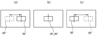
- the detected objects W ′ and W ′′ are provided at the same position in the pair of images captured by the pair of CCD cameras C1 and C2.
- FIG. 10B is a diagram in which a pair of images captured by a pair of imaging devices are superimposed, and W ′ is a detected object W captured by the right CCD camera C1, W '' Is a detected object W imaged by the left CCD camera C2. Further, a cylindrical body having a diameter of 145 mm is used as the detection object W.
- FIGS. 10 (a) and 10 (c) are diagrams in which a pair of images captured by the pair of CCD cameras C1 and C2 are superimposed, and FIG. 10 (a) is a front side of 110 mm from the intersection of the optical axes.
- FIG. 10C is a diagram illustrating an image captured by the pair of CCD cameras C1 and C2 in a state where the detection target W is positioned on FIG. 10, and FIG. 10C illustrates the detection target W positioned 150 mm deep from the intersection of the optical axes. It is a figure which shows the image imaged with a pair of CCD camera C1, C2 in the state to carry out. Then, as the difference between the imaging positions of the detection object W, the difference between the center positions of the detection objects W ′ and W ′′ in each of the pair of images (indicated by arrows in FIGS. 10A and 10B) is used. Yes.
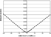
- FIG. 12 is a graph showing the amount of change in the imaging position of the detected object W when the detected object W is moved by a set amount from the near side in the depth direction toward the far side.
- the imaging of the detected object W is performed according to the actual movement of the detected object W.
- the difference in position also changes equally or substantially equally.
- the detected object W depends on the actual movement of the detected object W.
- the difference in the image pickup positions does not change uniformly or substantially uniformly.
- the determining means When the position of the detected object W is determined based on the difference in the imaging position of the detected object W that does not change evenly or substantially uniformly according to the actual movement of the detected object W, the determining means The reliability of the position of the detected object thus obtained is low, and it is considered that the determination of the position of the detected object with respect to the reference position is uncertain.
- the at least one image pickup device includes a first image pickup device and a second image pickup device that are provided so that optical axes intersect each other at an intersection, and the first image pickup device and the second image pickup device are provided.
- the position of the core relative to the reference position in the depth direction from the near side to the far side along the second imaginary line extending perpendicularly to the first imaginary line connecting the imaging device and passing through the intersection of the optical axes The control means includes a discriminating unit that discriminates based on a difference in imaging position of the core in a pair of images captured by the first imaging device and the second imaging device, and the discriminating unit is configured to determine an intersection of the optical axes.
- the detection range is a range that is more than the set distance from the intersection of the optical axes on the near side or the back side in the depth direction of the intersection of the optical axes. It is preferable that the position of the detected object in the depth direction in the detection range with respect to the reference position is determined based on a difference in imaging position of the detected object in a pair of captured images. .
- the range that is less than the set distance from the intersection of the optical axes on the near side and the far side in the depth direction of the intersection of the optical axes is at least the position of the detected object that is the apparatus side support relative to the reference position in the depth direction. Since this determination is uncertain, this range is set as a non-detection range, and a range that is more than the set distance from the intersection of the optical axes on the near side or the deep side of the intersection of the optical axes is relative to the reference position in the depth direction. Since the determination of the position of the detected object is reliable or substantially reliable, this range is set as the detection range.
- the determination unit is configured to determine the depth direction of the detected object in the detection range based on the difference in the imaging position of the detected object in the pair of images captured by the pair of image capturing apparatuses of the first image capturing apparatus and the second image capturing apparatus. The position relative to the reference position is determined.
- the detection range for determining the position of the object to be detected with respect to the reference position in the depth direction by the determination means is determined to be a range that is at least a set distance from the intersection of the optical axes to the near side or the far side.
- the position of the object to be detected with respect to the reference position in the depth direction can be reliably or substantially reliably determined by the means.
- the actual position is 10 mm or more away from the intersection of the optical axes.
- the position of the detected object relative to the reference position in the depth direction can be determined by setting 10 mm as the set distance. Can be reliably or substantially reliably performed. Accordingly, it is possible to provide an automatic transport facility for a roll body that can accurately determine at least the position of the detection object that is the apparatus-side support.
- the learning object to be detected is located at a first detection location between the first imaging device and the second imaging device in the detection range and in the direction along the first imaginary line.
- the learning object located at the second detection location shifted in the depth direction from the first detection location between the two imaging devices in the pair of images captured by the first imaging device and the second imaging device.
- the first corresponding to the position in the depth direction of the learning object based on the difference in the imaging position of the learning object and the position in the depth direction of the first detection point and the second detection point.
- the discriminating means is a pair captured by the first imaging device and the second imaging device.
- the position of the detected object in the depth direction with respect to the reference position in the detection range is determined based on the difference in the imaging position of the detected object in the image of the image and the correspondence relationship learned by the learning means. It is preferable that it is comprised.
- the difference from the position of the learning object in the image captured at the position is obtained as the parallax for the first detection location.
- the learning object located at the second detection location is picked up by a pair of image pickup devices, the position of the learning detection object in the image picked up by one image pickup device and the other image pickup position are displayed.
- the difference from the position of the learning object in the captured image is obtained as the parallax for the second detection location. Then, based on the parallax for the first imaging location and the position in the depth direction of the first detection location, and the parallax for the second imaging location and the position in the depth direction of the second detection location, The correspondence relationship between the position in the depth direction and the difference between the imaging positions of the objects to be detected in the pair of images captured by the pair of imaging devices is learned.
- the difference in the imaging position of the detected object also changes by the same amount or substantially the same amount. Further, even if the distance from the intersection point o of the optical axis of the imaging device, the intersection angle of the optical axes, or the like changes from the above-described experimental conditions, as shown in FIG. 21, for example, If the object to be detected is moved far away from the back side, the difference in the imaging position of the object to be detected will change by the same or approximately the same amount if the actual amount of movement of the object to be detected is the same. ing.
- the learning means learns the correspondence as shown in FIG. 23, for example, so that the determination means images the detected object with a pair of imaging devices and the imaging device captures the images with one imaging device. Based on the difference between the position of the detected object in the image and the position of the detected object in the image captured by the other imaging device, the position of the detected object in the depth direction with respect to the reference position can be determined.
- the determination means In the case of determining the position of the object to be detected by triangulation, information on the installation position where the pair of imaging devices of the first imaging device and the second imaging device is installed, information on the installation angle, and the like are given to the determination means. Since it is necessary to accurately install the pair of imaging devices so that the given installation position and installation angle are obtained, it takes time to install the imaging device. However, according to this configuration, by learning the relationship between the position in the depth direction of the learning object to be detected and the difference in the imaging position of the learning object in the pair of images captured by the pair of imaging devices. Even if the mounting accuracy of the imaging device is low to some extent, the position of the detected object can be determined from the relationship obtained by learning, so that the imaging device can be easily installed.
- the determination means sets a range that is more than the set distance from the intersection of the optical axes to the back side in the depth direction as a non-detection range, and the front of the depth direction from the intersection of the optical axes.
- the depth direction of the object to be detected with respect to the reference position in the detection range based on imaging information captured by the first imaging device and the second imaging device, with a range that is more than the set distance on the side as a detection range It is preferable to be configured to discriminate the position at.
- the first imaging device and the second imaging device have the same distance from the intersection of the optical axes, and the intersection angles of the optical axes with respect to a line segment parallel to the depth direction are the same. It is preferable that they are arranged in a distributed manner.
- a pair of image pickup devices of the first image pickup device and the second image pickup device are arranged in a distributed manner at positions where the distances from the fulcrum of the optical axis are equal and the crossing angles with respect to a line segment parallel to the depth direction are equal.
- the determination unit is configured to detect the positions of both ends of the detected object in a direction corresponding to the depth direction in each of a pair of images captured by the first imaging device and the second imaging device.
- the center position of the detected object in a direction corresponding to the depth direction in each of the pair of images is obtained from the positions of both ends of the detected object, and the detected object in each of the pair of images It is preferable that the position of the detected object in the depth direction with respect to the reference position in the detection range is determined based on a difference between the center positions of the detected objects.
- the positions of both ends of the object to be detected in the direction corresponding to the depth direction in each of the pair of images captured by the pair of image capturing apparatuses of the first image capturing apparatus and the second image capturing apparatus are detected.
- the center position of the detected object in the direction corresponding to the horizontal direction in each of the pair of images is obtained from the positions of both ends of the object, and the detected object is based on the difference in the center position of the detected object in each of the pair of images. Since the position with respect to the reference position in the depth direction is determined, the position of the detected object can be determined with less error.
- the position of one end of the detected object in a direction corresponding to the depth direction in each of the pair of images captured by the first imaging device and the second imaging device is detected, and each of the pair of images is detected. It is conceivable to determine the position of the detected object relative to the reference position in the depth direction based on the difference in one end position of the detected object, but if the position of the detected object is determined in this way, If a position shifted from one end of the detected object is erroneously detected as one end of the detected object, the position of the detected object to be determined is also shifted and determined in the same manner. However, as described above, the detected object in each of the pair of images is detected.
- the error in the detection position of the detected object can be halved by discriminating the center position between the one end of the detected object and the other end of the detected object accurately as the position of the detected object. It can be determined that there is little error.
- the determination unit is configured to add a direction along the first imaginary line in addition to the depth direction based on the imaging information captured by the first imaging device and the second imaging device, or It is preferable that the position of the detected object with respect to the reference position in a direction orthogonal to the depth direction and the direction along the first imaginary line is determined.
- the discrimination means is a position in two directions, ie, a depth direction and a direction along the first imaginary line, or a position in two directions, a depth direction and a direction perpendicular to the direction along the depth direction and the first imaginary line.
- the two-dimensional position of the detected object with respect to the reference position can be determined.
- the determining means can detect the three-dimensional object to be detected with respect to the reference position from the position in the three directions of the depth direction, the direction along the first imaginary line, and the direction orthogonal to the depth direction and the direction along the first imaginary line. Can be determined.
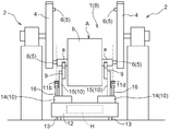
- FIG. 3 is a perspective view of a transport cart.
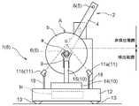
- FIG. 3 is a side view of the transport carriage.
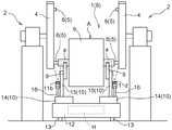
- These are front views of a conveyance trolley.
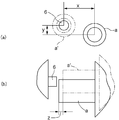
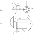
- These are figures which show a roll body and a pair of apparatus side support body.
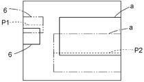
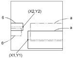
- These are figures which show the front view image by the imaging device for front view in 1st Embodiment.
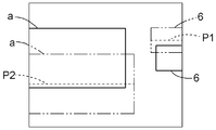
- These show the perspective image by the imaging device for perspectives in 1st Embodiment.
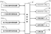
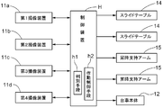
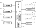
- These are the control block diagrams in 1st Embodiment.
- These are top views which show a pair of imaging device and to-be-detected object in experiment and embodiment.
- These are figures which show the image imaged with a pair of imaging device in experiment.
- control block diagrams in 2nd Embodiment are figures which show the difference of the imaging position in experiment. These are figures which show the 1st detection location and 2nd detection location in experiment. These are figures which show the learned correspondence in 3rd Embodiment. These are figures which show the 1st image in 3rd Embodiment. These are figures which show the 2nd image in 3rd Embodiment. These are the control block diagrams in 3rd Embodiment.
- the production facility is provided with an automatic transport vehicle 1 for roll bodies, a chucking device 2 as a receiving device, and the like.
- the chucking device 2 (gripping device) is provided in a production machine or the like that performs printing or coating on the surface of a printing base paper or various film raw fabrics.
- the roll body automatic transport vehicle 1 is installed in a production facility to deliver the roll body A to the chucking device 2 and automatically travels to a delivery point along a guide line laid on the floor surface.
- the roll body A is configured to be transferred to the chucking device 2.
- the roll body A is composed of a core a and a sheet material b such as paper or film wound around the core a.
- the core a located at the center of the roll body A is formed from the sheet material b. Projects on both sides in the axial direction.
- the chucking device 2 of the production facility includes a pair of rotating arms 4 that are rotatable around a rotation axis located at the center in the longitudinal direction, and a support tool that supports the roll body A and rotates together with the rotating arm 4. 5.
- Each of the pair of rotating arms 4 includes a support pin 6 supported as a support 5 at each of its longitudinal ends. Accordingly, each of the pair of rotating arms 4 includes a support pin 6 that functions as a pair of device-side supports.
- the support 5 is configured to support the roll body A by separately supporting both ends of the core a with the pair of support pins 6.
- the support 5 (the pair of support pins 6) rotates and stops the pair of rotating arms 4 in a state in which the rotation phases thereof coincide with each other, whereby the receiving position (the rotation axis of the rotating arm 4 in FIG. 2).
- the position is switched between a position at the lower left of the center) and a processing position (the position at the upper right of the rotation axis of the rotating arm 4 in FIG. 2).
- the roll body A is received from the automatic transport vehicle 1 for roll bodies
- the sheet material b is transferred from the supporting roll body A.
- the sheet material b is subjected to processing such as printing and coating on the production machine.
- the support pins 6 are provided at both ends in the longitudinal direction of the rotary arm 4, and the support 5 has the other support 5 in the processing position when one support 5 is located at the receiving position.
- a pair is provided so as to be located at the center.
- the pair of support pins 6 facing each other are supported by the respective rotating arms 4 so as to be close to and away from each other by the operation of an electric motor (not shown). Then, the core a is positioned at an appropriate position where both ends of the core a can be supported by the pair of support pins 6 and the support 5 is positioned at the receiving position (see FIG. 4A).
- the support pin 6 in the close state see FIG. 4B
- both ends of the core a are supported by the pair of support pins 6, and the support pins 6 in the close state are separated from each other.
- the support to both ends of the core a by the pair of support pins 6 is released.
- Each front end portion of the support pin 6 is formed in a cylindrical shape whose outer shape is smaller than the inner diameter of the core a, and the front end portion of the support pin 6 is brought into a state where the pair of support pins 6 are brought close to each other. It is inserted into the core a. Further, the tip end portion of the support pin 6 is configured to increase in diameter from a small cylindrical shape, and the tip end portion of the support pin 6 is enlarged in a state where the tip end portion is inserted into the core a. Thus, the end of the core a is supported by the support pin 6.
- the approach and separation directions of the pair of support pins 6 and the direction of the rotation axis of the rotary arm 4 are the same as the direction along which the axis of the core a (the axis of the roll body A) is positioned at an appropriate position.
- the appropriate position of the core a is specifically the axial center of the pair of support pins 6 and the core a of the core a in a state where the axial centers of the pair of support pins 6 positioned at the receiving position are aligned on a straight line. Are positions aligned in a straight line in the axial direction.
- the roll automatic transport vehicle 1 As shown in FIGS. 1 to 3, the roll body automatic transport vehicle 1 is supported by a mounting base 9 as a transporting vehicle side support that supports the roll body A above the transporting carriage 8, and the mounting base 9.
- the transport carriage 8 includes a control device H serving as a control means for controlling the operation of the movement operation means 10 based on the above, and a carriage body 12 provided with traveling wheels 13.
- control means, control device, discriminating means, and operation control means in this specification include all or some of the components of a conventional computer such as a CPU, memory, and communication unit, and are described in this specification.
- the algorithm necessary for executing is stored in the memory.
- the determination unit and the braking control unit are implemented by an algorithm of the control device.
- the transport carriage 8 includes a carriage body 12, a mounting base 9, a movement operation means 10, an imaging device 11, and a control device H.
- the mounting tables 9 are provided side by side in the left-right direction of the vehicle body so as to separately support both end portions of the core a protruding from the sheet material b, and each of the pair of mounting tables 9 has an upper end portion in the left-right direction of the vehicle body. It is formed in a V shape as viewed, and the end of the core a is placed and supported on the upper end of the V shape to place and support the roll body A in a fixed position with respect to the placement table 9. It is configured as follows.
- the mounting base 9 is comprised so that the edge part of the core a may be mounted and supported as mentioned above, the front-end
- the movement operation means 10 includes a slide table 14 slidably movable in the left-right direction and the front-rear direction of the vehicle body 12 with respect to the carriage main body 12, and is erected in a fixed state on the slide table 14 and has the mounting table 9 in the vertical direction And an elevating support arm 15 that is movably supported.
- the elevating support arms 15 are provided side by side in the left-right direction of the vehicle body so as to support the pair of mounting tables 9 so as to be movable up and down separately, and the slide table 14 supports the pair of elevating support arms 15 separately.
- a pair is provided in the left-right direction.
- the slide table 14 belongs to the prior art, and as a whole, a table lower part fixed to the carriage main body 12, a table intermediate part provided to be movable in the left-right direction with respect to the table lower part, A table upper part that is movable in the front-rear direction with respect to the table intermediate part, and one fixed to one between the table lower part and the table intermediate part and between the table intermediate part and the table upper part, respectively.
- a plurality of guide rails and a guided member guided in the guide rails are provided.
- an electric motor connected to the table intermediate part via a driving force transmission member such as a ball screw, chain or gear to move the table intermediate part relative to the table lower part, and the table upper part moved relative to the table intermediate part
- a driving force transmission member such as a ball screw, a chain, and a gear
- the slide table 14 is not limited to one having this structure.
- any one of a robot arm having a joint and a conventional technique for moving a support target in the left-right direction of the vehicle body and the front-rear direction of the vehicle body may be employed.
- the elevating support arm 15 has a fixed part fixed to the slide table 14 and a movable part movable in the vertical direction with respect to the fixed part. Between the fixed part and the movable part, an electric motor connected to the other via a driving force transmission member such as a ball screw, chain, or gear is provided. That is, the moving operation means 10 slides the pair of slide tables 14 in the left-right direction and the front-rear direction of the vehicle body, thereby moving the pair of lifting support arms 15 and the pair of mounting bases 9 in the left-right direction of the vehicle body and the vehicle body.
- a driving force transmission member such as a ball screw, chain, or gear
- the moving operation means 10 is configured to move the core a by moving the pair of mounting tables 9. Specifically, by moving the pair of mounting bases 9 integrally, both ends of the core a are moved in the vertical direction, the vehicle body left-right direction, and the vehicle body front-rear direction with respect to the cart body 12 while maintaining the posture of the core a. It is configured to be moved.
- the moving operation means 10 moves the pair of mounting tables 9 in the vertical direction, the vehicle body left-right direction, and the vehicle body front-rear direction, respectively, so that both ends of the core a are moved in the vertical direction with respect to the cart body 12 individually.
- the posture of the core a is changed by moving in the vehicle body left-right direction and vehicle body front-rear direction.
- the image pickup apparatus 11 In a state where the image pickup apparatus 11 is stopped at the delivery position, the image pickup apparatus 11 is placed on the main body 12 of the carriage so that the image pickup apparatus 11 simultaneously images the support pin 6 and the core a within one image pickup range.
- the image pickup apparatus and the image pickup means have a function of transmitting image data to a CCD image sensor, a CMOS image sensor, a photoelectric conversion element such as an organic photoconductive film (OPC), and a control device. Including imaging devices can be used. Then, as the imaging device 11, the one-side front imaging device 11 a and the one-side perspective imaging device that images one of the pair of support pins 6 and one end of the core a in a state where the conveyance carriage 8 is stopped at the delivery position.
- OPC organic photoconductive film
- a total of four units are provided in the cart body 12.
- Each of the four image pickup devices 11 is supported on the upper end portion of a support bar 16 standing in a fixed state on the cart body 12 so that the height and orientation of the support device 16 can be adjusted.
- a pair of one-side front imaging device (first imaging device) 11a and one-side perspective imaging device (second imaging device) 11b, and the other-side front imaging device (third imaging device) 11c and the other-side perspective A pair with the image pickup device (fourth image pickup device) 11d is provided in a state where the image pickup directions intersect when viewed in the axial direction of the core a.
- the one-side imaging device 11a and the one-side perspective imaging device 11b correspond to one-side imaging device
- the other-side front-side imaging device 11c and the other-side perspective imaging device 11d correspond to the other-side imaging device.
- the axial direction of the core a as viewed in the axial direction is the axial direction of the core a positioned at an appropriate position corresponding to the pair of support pins 6 positioned at the receiving position.
- the direction is the same as the left-right direction of the vehicle body when the vehicle is stopped at the position.
- the one-side front imaging device 11 a is located behind the core a that is moved by the moving operation means 10 and is within a vertical movement range of the core a that is moved by the moving operation means 10.
- the vehicle body 12 is provided at the rear of the vehicle body 12 in the left-right direction of the vehicle body 12 so as to be positioned on the outer side of the vehicle body left-right direction with respect to the mounting table 9 on one side.
- the one-side perspective imaging device 11b is positioned on the lower front side of the core a that is moved by the moving operation means 10, and is positioned on the outer side in the vehicle body left-right direction with respect to the one-side mounting table 9.
- the vehicle body 12 is provided at the front of the vehicle body in the left-right direction end side.
- the other-side front imaging device 11c is located behind the core a moving by the movement operation means 10 and at a height within the vertical movement range of the core a moving by the movement operation means 10, and
- the carriage main body 12 is provided at the rear of the vehicle body left and right direction other end side so as to be located on the outer side in the vehicle body left and right direction with respect to the mounting table 9.
- the other-side perspective imaging device 11d is positioned on the lower front side of the core a that is moved by the moving operation means 10, and is positioned on the outer side of the left-right direction of the vehicle body with respect to the mounting table 9 on the other side. It is provided at the front of the other side of the body 12 in the left-right direction of the vehicle body.
- the one-side front imaging device 11a and the other-side front imaging device 11c are provided in such a posture that the imaging direction is to be imaged horizontally forward.
- the one-side perspective imaging device 11b and the other-side perspective imaging device 11d are provided in such a posture that the imaging direction is obliquely upward and rearward.
- the one-side front imaging device 11a and the one-side perspective imaging device 11b are located at the appropriate positions with the tip of the support pin 6 on the one side located at the receiving position in a state where the transport carriage 8 is stopped at the delivery position. It is provided so that one end part of the core a may be imaged.
- the other-side front imaging device 11c and the other-side perspective imaging device 11d are configured such that, with the transport carriage 8 stopped at the delivery position, the distal end portion of the other-side support pin 6 positioned at the receiving position and the core a at the appropriate position. It is provided so that it may image the other end part of.
- FIG. 5 is an image captured by the one-side front imaging device 11a
- FIG. 6 is an image captured by the one-side perspective imaging device 11b.
- the one-side support pin 6 is positioned at the receiving position as shown by a solid line in FIGS.
- an image captured by the one-side front imaging device 11a hereinafter referred to as a front-view image
- one-side perspective imaging by capturing an image when the transport carriage 8 is stopped at the delivery location.
- an image captured by the device 11b hereinafter referred to as a perspective image
- the tip of the support pin 6 on one side is captured at an appropriate position and at an appropriate size.
- the support pin 6 on one side is positioned away from the receiving position, or the conveyance carriage 8 is displaced from the delivery position and stops or vibrates during conveyance.
- the support pin 6 on one side and the transport carriage 8 are relatively displaced in the vertical direction or in the left-right direction of the vehicle body due to a being supported by being shifted from an appropriate support position on the mounting table 9, the front side In the visual image or the perspective image, the tip of the support pin 6 on one side is picked up from the appropriate position in the vertical direction of the image or in the horizontal direction of the image, and the support pin 6 on the one side and the transport carriage 8 are relatively relative to the vehicle body.
- the front end portion of the support pin 6 on one side is imaged smaller or larger than the appropriate size in a front view image or a perspective image.
- the one-side support pin 6 is provided as shown by a solid line in FIGS.
- the transport carriage 8 is stopped at the delivery position and the core a is positioned at an appropriate position, one end of the core a is appropriate at an appropriate position in the front view image and the perspective image. Images are captured in a large size. 5 and 6, when the core a is positioned so as to be deviated from the appropriate position in the vertical direction or the left-right direction of the vehicle body, or one side of the core a is positioned at the appropriate position.
- the front view In the image and the perspective image one end portion of the core a is picked up from the appropriate position in the image vertical direction or the image left-right direction, and when the core a is shifted from the proper position in the vehicle longitudinal direction, the proper position of the core a is When it deviates in the vehicle longitudinal direction with respect to the transport carriage 8, one end of the core a is imaged smaller or larger than the appropriate size in the front view image and the perspective image.
- the other-side front imaging device 11c and the other-side perspective imaging device 11d include the one-side front imaging device 11a or the one-side perspective imaging device 11b and the one end of the core a.
- the other side front imaging device 11c and the other side perspective imaging device 11d Description is omitted.
- the control device H controls the operation of the carriage main body 12 so that the transport carriage 8 travels along the guide line and automatically travels to the delivery location, and in the state where the transport carriage 8 is stopped at the delivery location, the four imaging devices
- the apparatus 11 is operated simultaneously to control the operation of the imaging apparatus 11 so that the support pins 6 and the core a are imaged in a single imaging range in each of the four imaging apparatuses 11, and 4
- the operation of the moving operation means 10 is controlled so as to position the core a at an appropriate position based on the imaging information imaged by the imaging device 11 of the table.
- FIG. 8 is a control block diagram of the roll automatic transport vehicle.
- the core Based on the imaging information imaged by the one-side front imaging device 11a and the one-side perspective imaging device 11b, the core a deviation amount y in the up-down direction, a deviation amount z in the vehicle body left-right direction, and a displacement amount x in the vehicle body front-rear direction with respect to the one-end appropriate position a ′ at one end portion of a.
- One mounting table 9 is moved in the up-down direction, the left-right direction of the vehicle body, and the front-rear direction of the vehicle body based on y and z, so that one end of the core a is positioned at one end proper position a ′.
- the amount of vertical displacement y with respect to the other end proper position a ′ at the other end of the core a is obtained.
- the other mounting table 9 is moved vertically. And the other end of the core a is positioned at the other end proper position.
- one end of the core a is positioned at the one end proper position, and the other end of the core a is positioned at the other end proper position.
- the core a can be positioned at an appropriate position.
- the deviation amount x in the vertical direction and the vehicle body longitudinal direction with respect to the one-end-side appropriate position a ′ at one end of the core a is obtained as follows. That is, based on the image information imaged by the one-side front imaging device 11a, the image vertical direction of the axial center position P1 of the support pin 6 in the front view image from the upper side position and the lower side position of the support pin 6 in the front view image. The position of the axis P1 of the support pin 6 in the perspective image is determined from the upper side position and the lower side position of the support pin 6 in the perspective image based on the image information captured by the one-side perspective imaging device 11b. The position in the vertical direction of the image is obtained.
- the axial center position P1 of the support pin 6 in the vertical direction of the image in the front view image, the axial position P1 of the support pin 6 in the vertical direction of the image in the perspective image, the one-side front imaging device 11a and the preset one side The axis of one support pin 6 based on the intersection angle information with the side strabismus imaging device 11b and the preset position information of the one side front imaging device 11a and the one side squint imaging device 11b.
- the position of the center with respect to the cart body 12 in the vertical direction and the vehicle body longitudinal direction is determined.
- the upper and lower positions of the core a in the front view image from the axial position P2 of the core a in the front view image in the vertical direction of the image.
- the position is obtained, and based on the image information captured by the one-side perspective imaging device 11b, the upper and lower positions of the core a in the perspective image in the vertical direction of the axis position P2 of the core a in the perspective image. Is required.
- the core a based on the axial position P2 of the core a in the vertical direction of the image in the front view image, the axial position P2 of the core a in the vertical direction of the image in the perspective image, and the preset intersection angle information, the core a The position of the axial center of one end of the vehicle with respect to the traveling carriage 12 in the vertical direction and the vehicle body longitudinal direction is obtained. And based on the axial center position P1 of one supporting pin 6 and the axial center position P2 of one end part of the core a determined as described above, the vertical direction relative to the one supporting pin 6 at one end part of the core a is determined.
- each of the one-side front imaging device 11a and the one-side perspective imaging device 11b is provided such that the optical axis is along the vertical plane.
- the shift amount z in the left-right direction of the vehicle body with respect to the one-end appropriate position a ′ at one end of the core a is obtained as follows. That is, the position of the support pin 6 in the horizontal direction of the image in the front view image is obtained from the tip position of the support pin 6 in the front view image based on the image information captured by the one-side front imaging device 11a. Based on the image information captured by the side front imaging device 11a, the position of the core a in the left-right direction of the image in the front view image is obtained from the tip position of the core a in the front view image.
- the vehicle body left-right direction of one end of the core a with respect to one support pin 6 The shift amount z in the left-right direction of the vehicle body from the one end side reference position a ′ at one end portion of the core a is determined.
- the deviation in the vertical direction, the lateral direction of the vehicle body, and the longitudinal direction of the vehicle body relative to the other end side proper position in the other end portion of the core a is the vertical direction, the lateral direction of the vehicle body, Since it is calculated
- Each of the other-side front-view imaging device 11c and the other-side perspective imaging device 11d is provided so that the optical axes are along the vertical plane, and the crossing angle of these optical axes is the one-side front-view imaging device 11a. And the crossing angle of the optical axis of the one-side perspective imaging device 11b.
- the control device H controls the operation of the moving operation means 10 to position the core a at an appropriate position, and then transmits a delivery preparation completion signal to the chucking device 2 by communication means not shown.
- the chucking device 2 receives the signal indicating completion of delivery, the chucking device 2 brings the pair of support pins 6 located at the receiving position close to each other, and then enlarges the diameter of each of the tip portions of the pair of support pins 6 by air sealing or the like. The both ends of the roll body A are supported.
- a second embodiment according to the present invention will be described.
- the same parts as those in the first embodiment are denoted by the same drawing numbers, and description thereof will not be repeated basically.
- the imaging device 11 a first imaging device 11 a and a second imaging device 11 b that take an image of one of the pair of support pins 6 and one end of the core a as an object to be detected in a state where the transport carriage 8 is stopped at the delivery position.
- a pair of imaging devices 11 is provided, and the cart body 12 is provided with two pairs of imaging devices 11 for a total of four imaging devices 11. Then, each of the four imaging devices 11 has the carriage main body 12 so that the support pin 6 and the core a are simultaneously placed in one imaging range and imaged in a state where the transport carriage 8 is stopped at the delivery position. Is provided. Each of the four image pickup devices 11 is supported on the upper end portion of a support bar 16 standing in a fixed state on the cart body 12 so that the height and the direction of the support device 16 can be adjusted.
- the first imaging device 11 a and the third imaging device 11 c are positioned below and above the moving range of the core a that is moved by the moving operation means 10, and above the upper side. It is installed in the cart main body 12 in a state in which an image is taken obliquely forward. Further, the second imaging device 11b and the fourth imaging device 11d are located below and in front of the moving range of the core a that is moved by the moving operation means 10, and the support pin 6 and the core a are The trolley body 12 is installed in a state where an image is taken obliquely rearward toward the upper side.
- the pair of imaging devices 11 of the first imaging device 11a and the second imaging device 11b have optical axes that intersect with each other, are located on the lower side with respect to the intersection o of the optical axes, and Dispersed and arranged in a state of being located on both sides in the longitudinal direction of the vehicle body with respect to the intersection point o.
- the pair of imaging devices 11 of the first imaging device 11a and the second imaging device 11b have the same distance from the intersection point o of the optical axes and the same crossing angle of the optical axes with respect to a line segment parallel to the vertical direction.
- the optical axis is positioned on the same vertical plane as the support pin 6 and the height relative to the carriage main body 12 is the same height, and the intersection point o of the optical axes.
- the vehicle is distributed in a state where the distances in the vehicle longitudinal direction from the vehicle are equal.
- the vertical direction corresponds to the depth direction
- the lower side corresponds to the near side in the depth direction
- the upper side corresponds to the far side in the depth direction.
- the vehicle body longitudinal direction corresponds to the direction along the first imaginary line of the present invention
- the vehicle body lateral direction corresponds to the direction perpendicular to the depth direction and the direction along the first imaginary line.
- the optical axis is a straight line connecting the centers of curvature of the lenses of the imaging device 11.
- the depth direction is the first imaging device 11a (imaging device at the position C1 in FIG. 9) and the second imaging device 11b (imaging image at the position C2 in FIG. 9). This is a direction from the near side to the far side along the second imaginary line PL2 that extends perpendicularly to the first imaginary line PL1 that connects the device) and passes through the intersection of the optical axes.
- This first virtual line PL1 is defined as a virtual line passing through a point through which the optical axis on the surface of the lens of one imaging device 11 passes and a point through which the optical axis on the surface of the lens of the other imaging device 11 passes. can do.
- the definition of the first virtual line PL1 is not limited to this.
- the first virtual line PL1 may be defined as a straight line connecting a point in one imaging device and a point at a position corresponding to the one point in the other imaging device. More preferably, the straight line is included in a plane including two optical axes of the pair of imaging devices.
- the pair of imaging devices 11 of the first imaging device 11 a and the second imaging device 11 b is in a state where the support pin 6 and the core a are present in a state where the transport carriage 8 is stopped at the delivery position.
- the support pin 6 is positioned so that the support pin 6 is moved in the vertical direction with respect to the transport carriage 8 because the support pin 6 is stopped while being shifted from the receiving position or the transport carriage 8 is stopped after being shifted from the delivery position. In some cases, the position is shifted in the longitudinal direction of the vehicle body. Considering this shift, the intersection point o of the optical axes is positioned above the range where the support pins 6 are assumed to exist.
- the intersection o of the optical axes is above the set distance from the range in which the moving range of the core a and the support pin 6 are assumed to exist. It is distributed so as to be located.
- the support pin 6 and the core a are located in a detection range that is at least a set distance away from the intersection point o of the optical axes on the lower side in the vertical direction of the intersection point o of the optical axes. I have to.
- a range that is less than the set distance from the optical axis intersection point o on the upper and lower sides of the optical axis intersection point o is set as a non-detection range so that the support pin 6 and the core a are not located in the non-detection range.
- a range equal to or more than a set distance from the optical axis intersection o on the upper side in the vertical direction of the optical axis intersection o is also set as a non-detection range so that the support pin 6 and the core a are not located in the non-detection range.
- pair of imaging devices 11 of the third imaging device 11c and the fourth imaging device 11d are distributed and arranged in the same manner as the pair of imaging devices 11 of the first imaging device 11a and the second imaging device 11b. Description of the arrangement of the pair of imaging devices 11 of the imaging device 11c and the fourth imaging device 11d is omitted.
- the first imaging device 11 a is imaged by imaging when the support pin 6 on one side is located at the receiving position and the transport carriage 8 is stopped at the delivery position.
- the tip of the support pin 6 on one side is appropriate in the image captured by the first imaging device (hereinafter referred to as the first image) and the image captured by the second imaging device 11b (hereinafter referred to as the second image). Images are taken at various positions. Then, as shown by solid lines in FIGS.
- the support pin 6 on one side is displaced when the support pin 6 on one side is displaced from the receiving position or stops when the carriage 8 is displaced from the delivery position.
- the tip of the support pin 6 on one side is imaged with an offset from an appropriate position in both or one of the first image and the second image.
- the imaging of the one end of the core a is supported by the core a being displaced from the proper support position by the mounting table 9 due to vibration during conveyance.
- one end part of a and the transport carriage 8 are relatively displaced, one end part of the core a is imaged by shifting from an appropriate position in both or one of the first image and the second image.
- FIG. 17 is a first image captured by the first imaging device 11a
- FIG. 18 is a second image captured by the second imaging device 11b. These first image and second image.
- the control device H and the support pins 6 and the core in the vertical direction, the longitudinal direction of the vehicle body, and the lateral direction of the vehicle body a with respect to the position of the transport carriage 8 (specifically, the position relative to the intersection point o of the optical axis set in advance with respect to the transport carriage 8, and the intersection point o of the optical axis corresponds to the reference position in the present invention).
- Determining means h1 for determining, and operation control for controlling the operation of the moving operation means 10 to position the core a at an appropriate position based on the positions of the support pin 6 and the core a determined with respect to the determining position h1.
- the operation control means h2 controls the operation of the carriage main body 12 so that the transport carriage 8 travels along the guide line and automatically travels to the delivery place, and in the state where the transport carriage 8 is stopped at the delivery place,
- the imaging devices 11 are operated simultaneously, and the operation of the imaging devices 11 is controlled so that each of the four imaging devices 11 captures the support pin 6 and the core a within a single imaging range. It is also configured.
- FIG. 16 is a control block diagram of the roll automatic transport vehicle.
- the determination of the positions of the support pin 6 and the core a by the determination unit h1 will be described. Based on the image information captured by the first imaging device 11a, the positions of the upper and lower sides of the support pin 6 in the first image are detected, and the positions of the upper and lower sides of the support pin 6 are determined from the positions of both ends. The position of the axis P1 of the support pin 6 in one image in the vertical direction of the image is obtained.
- the position of the both ends of the upper side and lower side of the support pin 6 in a 2nd image is detected, and the position of the both ends of this support pin 6 upper side and lower side Therefore, the position of the axis P1 of the support pin 6 in the second image in the vertical direction of the image is obtained.
- the position of the axis P1 of the support pin 6 in the vertical direction of the image in the first image, the position of the axis P1 of the support pin 6 in the vertical direction of the image in the second image, and the first imaging device 11a set in advance.
- the position of the axis of one support pin 6 in the vertical direction with respect to the transport carriage 8 and the longitudinal direction of the vehicle body is determined as coordinates based on the intersection point o of the optical axes.
- the axis P1 corresponds to the center position of the support pin 6.
- the positions of both ends of the upper side and the lower side of the core a in the first image are detected based on the image information captured by the first imaging device 11a, and the first position is determined from the positions of both ends of the upper side and the lower side of the core a.
- the position in the image vertical direction of the axial center position P2 of the core a in one image is obtained, and the positions of the upper side and the lower side of the core a in the second image are determined based on the image information captured by the second imaging device 11b.
- the position in the vertical direction of the image of the axial center position P2 of the core a in the second image is obtained from the positions of both ends of the upper side and the lower side of the core a.
- the position of the axial center position P2 of the core a in the vertical direction of the image in the first image, the position of the axial center position P2 of the core a in the vertical direction of the image in the second image, and the preset first imaging device 11a Based on the crossing angle information with the second imaging device 11b and the position information of the first imaging device 11a and the second imaging device 11b set in advance, using a well-known position measurement technique with a stereo camera, The positions of the axial center of one end of the core a in the vertical direction and the longitudinal direction of the vehicle body with respect to the transport carriage 8 are determined as coordinates based on the intersection o of the optical axes.
- the up-down direction of the one end part of the core a with respect to one support pin 6 is demonstrated.
- the displacement amount y and the displacement amount x in the longitudinal direction of the vehicle body that is, the displacement amount y in the vertical direction and the displacement amount x in the longitudinal direction of the vehicle body from the one end side reference position a ′ for one end portion of the core a (FIG. 19A). Reference) is required.
- the position of the support pin 6 in the image left-right direction in a 1st image is calculated
- the position of the core a in the left-right direction of the image in the first image is obtained from the tip position of the core a in the first image.
- the deviation in the vertical direction, the lateral direction of the vehicle body, and the longitudinal direction of the vehicle body relative to the other end side proper position in the other end portion of the core a is the vertical direction, the lateral direction of the vehicle body, Since it is calculated
- the movement control unit h2 positions the core a at an appropriate position based on the shift amounts x, y, z obtained from the positions of the support pin 6 and the core a with respect to the traveling carriage determined by the determination unit h1.
- a signal indicating completion of delivery preparation is transmitted to the chucking device 2 by communication means not shown.
- the chucking device 2 receives the signal indicating completion of delivery, the chucking device 2 brings the pair of support pins 6 located at the receiving position close to each other, and then enlarges the diameter of each of the tip portions of the pair of support pins 6 by air sealing or the like. The both ends of the roll body A are supported.
- the determination of the position of the support pin 6 with respect to the reference position by the determination unit h1 is uncertain, so the intersections o and o of the optical axis at which the determination by the determination unit h1 is uncertain.
- a set distance is set so that the vicinity is a non-detection range, and a range that is more than the set distance from the intersection o of the optical axes on the lower side in the vertical direction of the intersection o of the optical axes is set as the detection range.
- the support pin 6 located in the detection range is imaged by the pair of imaging devices 11, and based on the difference in the imaging position of the support pin 6 in the pair of images captured by the pair of imaging devices 11.
- the position of the support pin 6 from the position is determined, and the position of the support pin 6 with respect to the reference position can be accurately determined by the determination means h1.
- the learning unit h3 learns the correspondence relationship between the imaging positions in a pair of images corresponding to the vertical direction instead of setting the intersection angle information and the position information of the imaging device 11 in advance. Since the configuration is the same as in the second embodiment except that the determination of the positions of the support pins 6 and the core a by the determination means h1 is different, the same reference numerals are given to the same configurations as in the second embodiment. The description is omitted, and the configuration different from the second embodiment will be mainly described.
- the reference position is picked up at the position of the intersection o when it is assumed that a pair of image pickup apparatuses 11 (for example, the first image pickup apparatus 11a and the second image pickup apparatus 11b) are accurately installed. This corresponds to the installation location of the device 11.
- the control device H includes an object to be detected in a pair of images captured by a pair of imaging devices corresponding to the vertical direction of the object to be detected.
- Learning means h ⁇ b> 3 is provided for learning the correspondence between the differences in the imaging positions.
- the learning unit h ⁇ b> 3 includes a pair of images obtained by capturing the learning object a ′ (shown by a solid line in FIG. 22) located at the first detection location with the pair of imaging devices 11.
- the learning object a in a pair of images obtained by imaging the difference between the imaging positions of the learning object (parallax) and the learning object a ′ located at the second detection location by the pair of imaging devices 11.
- the first detection location is set between the pair of imaging devices 11 in the detection range and the vehicle body longitudinal direction
- the second detection location is the first detection between the pair of imaging devices 11 in the detection range and the vehicle body longitudinal direction. It is set so as to be shifted downward from the location in the vertical direction.
- the line segment connecting the first detection location and the second detection location is set so as to pass through the intersection point o when the pair of imaging devices 11 are correctly attached.
- the detection location is set to a location 10 mm below the intersection o
- the second detection location is set to a location 20 mm below the intersection o.
- a detection member (dummy) formed in the same shape as the core a is used as the learning object a ′.
- an intermediate position (first position) between the edges of the upper edge and the lower edge in the longitudinal direction of the learning object a ′ on the first image captured by the first imaging device 11a.
- the coordinates (Xa, Ya)) on one image are obtained.
- the intermediate position (coordinates (Xb, Yb) on the second image) of these edges from the edge of the longitudinal edge of the upper side and the lower side of the learning object imaged by the second imaging device.
- the deviation amount between the intermediate position of the learning object a ′ on the first image and the intermediate position of the learning object a ′ on the second image is expressed by an equation based on the Pythagorean theorem: ⁇ ((Xa-Xb + (Ya-Yb ).
- the learning means h3 moves up and down in the vertical direction of one of the lifting support arms 15 to support the lifting as the learning object a ′ is moved up and down to the first detection position and the second detection position.
- a vertical movement relationship that is a relationship between the amount of movement of the arm 15 and the amount of shift between the first image and the second image is learned.
- the learning means h3 moves the learning object a ′ in the longitudinal direction of the vehicle and the learning object a on the first image when the learning object a ′ is thus moved.
- the one slide table 14 is moved in the vehicle longitudinal direction, and the learning object a' is moved in the vehicle longitudinal direction by a set amount to slide
- the front-rear movement relationship that is the relationship between the sliding amount of the table 14 in the vehicle front-rear direction and the movement amount of the learning object a ′ in the first image is learned.
- the learning unit h3 also moves the learning object a ′ in the vehicle lateral direction and the learning object a on the first image when the learning object a ′ is thus moved.
- one slide table 14 is moved in the vehicle width direction, and the learning object a ′ is moved by a set amount in the vehicle width direction, so that the slide table
- the lateral movement relationship that is the relationship between the sliding amount in the vehicle lateral direction of 14 and the movement amount of the learning object a ′ in the first image is learned.
- the third imaging device 11c, the fourth imaging device 11d, the other lifting support arm 15 and the other slide table 14 also correspond to the other end side of the learning object a ′ and have a vertical movement relationship.
- the front-rear movement relation and the horizontal movement relation are learned.
- the learning unit h3 places the learning object a ′ having the same shape as the core a on the mounting table 9 before or after the roll body automatic transport vehicle 1 is deployed on the roll body transport facility.
- the learning object a ′ is moved up and down and picked up at a plurality of positions by the pair of imaging devices 11, and the learning object a ′ in the pair of images at each of the positions is detected.
- the learning object a ′ (core a) on the image captured by the pair of imaging devices 11 is detected.
- the correspondence between the difference and the vertical position of the learning object a ′ (core a) is learned.
- the learning unit h3 also has a relationship (vertical movement) between the amount of movement of the learning object a ′ (core a) by the movement operation unit 10 and the amount of movement on the first image captured by the first imaging device 11a. Relationship, back-and-forth movement relationship, and lateral movement relationship).
- the determination of the positions of the support pin 6 and the core a by the determination unit h1 will be described.
- the intermediate positions of these edges from the edges of the upper and lower edges of the core a in the first image see FIG. 24, the core on the first image.
- the positions of the coordinates (X1, Y1)) of the a in the vertical direction and the horizontal width direction of the image are obtained.
- the intermediate positions of these edges from the edges of the longitudinal ends of the upper and lower sides of the support pin 6 in the first image see FIG. 24, first image
- the positions of the coordinates (X2, Y2) of the upper support pin 6 in the vertical direction and horizontal width direction of the image are obtained.
- the reference in the detection range The position (Pc) in the vertical direction of the core a with respect to the position (the position of the intersection o when it is assumed that the first imaging device 11a and the second imaging device 11b are accurately installed) is determined. Further, based on the difference (parallax) Gp between the intermediate positions (imaging positions) of the support pins 6 in the pair of images of the first image and the second image and the correspondence learned by the learning unit h3, The position (Pp) in the vertical direction of the support pin 6 with respect to the reference position is determined.
- the amount of deviation in the vertical direction between the support pin 6 and the core a can be obtained as a difference between the positions of the two relative to the reference position (Pc ⁇ Pp). Therefore, in order to eliminate the vertical displacement between the support pin 6 and the core a and to match the vertical positions of the two, the difference between the positions of the two (Pc ⁇ Pp) and the vertical movement relationship Based on the above, the movement control means h2 controls the operation of the elevating support arm 15 to move the core a up and down.
- the core a is moved to the vehicle based on the displacement and the longitudinal movement relationship.
- the movement control means h2 controls the operation of the slide table 14 to move in the front-rear direction. Further, in order to set the shift amount (Y1-Y2) in the image horizontal width direction between the core a on the first image and the support pin 6 on the first image to be a predetermined shift amount, this shift amount and the horizontal width movement relationship are used. Thus, the movement control means h2 controls the operation of the slide table 14 so as to move the core a in the vehicle lateral width direction.
- the discriminating means In short, in the second embodiment, information on the installation position where the pair of imaging devices are installed, information on the installation angle, and the like are given to the discriminating means, and the pair of imaging devices are accurately set so as to be the given installation position and installation angle.
- the third embodiment for learning in a pair of images taken by the pair of imaging devices and the position in the depth direction of the learning object to be detected, it is time consuming to install the imaging device.
- the difference in the imaging position of the detected object in the pair of images captured by the pair of imaging apparatuses can be obtained even if the mounting accuracy of the imaging apparatus is somewhat low. Since the position of the detected object can be determined from the relationship obtained by learning, it is easy to install the imaging device.
- the moving operation means 10 is configured to change the posture of the core a in addition to the movement of the core a by moving both ends of the core a separately.
- the first imaging device 11a and the second imaging device 11b which are provided in a state where the imaging directions intersect when viewed in the axial direction, and the imaging direction when viewed in the axial direction of the core a.
- a third imaging device 11c and a fourth imaging device 11d that are paired with the other imaging device are provided, and the control unit H controls the one end portion of the core a based on the imaging information of the one imaging device.
- the one end of the core a is positioned at an appropriate position at one end by moving in the vertical direction, the left and right direction of the vehicle, and the longitudinal direction of the vehicle, and the other end of the core a is moved in the vertical direction based on the imaging information of the other imaging device.
- Body left-right direction and body front-back direction The other end of the core a is positioned at the proper position at the other end, and the operation of the moving operation means 10 is controlled so as to position the core a at the proper position.
- the configurations of the imaging device 11 and the control unit H may be changed as appropriate.
- the moving operation means 10 is configured to allow only the movement of the core a in a state in which the both ends a of the core are integrally moved in the vertical direction, the vehicle body left-right direction, and the vehicle body front-rear direction to maintain the posture. Then, as the imaging device 11, a first imaging device 11a and a second imaging device 11b provided in a state where the imaging directions intersect in the axial direction of the core a are provided, and the control means H is provided as the first imaging device 11a.
- the second imaging device 11b based on the imaging information of the moving operation means 10 to move the both ends of the core a integrally in the vertical direction, the vehicle body left-right direction, and the vehicle body front-rear direction to position the core a in the proper position. You may comprise so that an action
- the control means H discriminate
- the position and size of the core a and the support pin 6 in the captured image in the vertical direction and the horizontal direction of the image are determined, and one end of the core a is connected to one end based on the imaging information of the first imaging device 11a.
- the moving operation means 10 is positioned at an appropriate position and the other end of the core a is positioned at the other end appropriate position based on the imaging information of the third imaging device 11c, so that the core a is positioned at the appropriate position. You may comprise so that an action
- the moving operation means 10 is configured such that both end portions of the core a are movable in the vertical direction, the left and right direction of the vehicle body, and the longitudinal direction of the vehicle body. May be configured to be movable in the direction, the left-right direction of the vehicle body, and the front-rear direction of the vehicle body. May be.
- four image pickup devices are provided as the image pickup device 11, one, two, or three image pickup devices among the four image pickup devices may be provided as the image pickup device 11.
- the apparatus-side support 6 and the core a are simultaneously imaged by one imaging device 11.
- the apparatus-side support 6 and the core a are captured by one imaging device 11.
- One image is picked up, and then the image pickup direction of the one image pickup device 11 is changed or moved so as to pick up the other of the device side support 6 and the core a.
- the apparatus 11 may image the apparatus side support 6 and the core a while shifting the time.
- the imaging device 11 includes an imaging device for the device for imaging the device-side support 6 and an imaging device for the core for imaging the core a.
- the side support 6 and the core a may be imaged separately or at different times.
- the control means H is used for the appropriate position based on the imaging information imaged by the front imaging device (one-side front imaging device 11a or the other-side front imaging device 11c).
- the shift amount z in the left-right direction of the vehicle body of the core a is obtained, and the imaging information captured by the front imaging devices 11a and 11c and the perspective imaging device (the one-side perspective imaging device 11b or the other-side perspective imaging device 11d).
- the vertical displacement amount y and the vehicle longitudinal displacement amount x of the core a with respect to the appropriate position are obtained.
- the vertical displacement amount y and the lateral displacement z of the core a with respect to the appropriate position are obtained, and the front imaging devices 11a and 11c
- the front imaging devices 11a and 11c Shoot Based on the imaging information of both the captured imaging information and the imaging information captured by the perspective imaging devices 11b and 11d, the displacement amount x of the core a in the longitudinal direction of the vehicle body with respect to the appropriate position is determined.
- the configuration of the control means H may be changed as appropriate.
- the imaging device 11 is provided on the carriage main body 12. However, the imaging device 11 is provided on the carrier side support 9 so that the imaging device 11 moves integrally with the carrier side support 9. May be.
- the imaging device 11 is provided on the carrier side support 9 in this way, the imaging device 11 is provided so as to image only the core a of the device side support 6 and the core a, and the control means H is provided.
- the operation of the moving operation means 10 can be controlled so as to position the core a at an appropriate position based on the imaging information in which only the core a is imaged by the imaging device 11.
- the position and orientation of the pair of imaging devices 11 can be appropriately changed as the pair of imaging devices 11 whose imaging directions intersect when viewed in the axial direction of the core a.
- An imaging device 11 is provided that is positioned below the core a that is moved by the operating means 10 and within the front-rear range of the vehicle body of the core a that is moved by the moving operating means 10 and that is provided in a posture to capture images vertically upward. May be.
- the pair of imaging devices 11 are dispersedly arranged at positions where the distances from the intersection point o of the optical axes are equal and the crossing angles of the optical axes are equal to the line segment parallel to the depth direction.
- the pair of imaging devices 11 may be dispersedly arranged at positions where the distances from the intersection point o of the optical axes are different, or may be dispersedly arranged at positions where the crossing angles of the optical axes with respect to the line segment parallel to the depth direction are different. Also good.
- the detection range is a range that is more than the set distance from the intersection of the optical axes on the near side (or the back side) in the depth direction from the intersection point o of the optical axes.
- the discrimination means detects the positions of both ends of the object to be detected in the direction corresponding to the depth direction in each of the pair of images captured by the pair of imaging devices.
- the center position of the detection object in the direction corresponding to the depth direction in each of the pair of images is obtained from the positions of both ends of the detection object, and based on the difference in the center position of the detection object in each of the pair of images
- the position of the detected object in the depth direction with respect to the position is determined.
- the determining means includes the detected object in a direction corresponding to the depth direction in each of the pair of images captured by the pair of imaging devices.
- the position of one end of the detected object may be detected, and the position of the detected object relative to the reference position in the depth direction may be determined based on the position of the one end of the detected object in each of the pair of images.
- the determination means adds three directions including the direction along the first imaginary line and the direction perpendicular to the direction along the depth direction and the first imaginary line in the depth direction.
- the determining means may be configured to determine the position of the detected object with respect to the reference position in only one direction in the depth direction.
- the determination unit is configured to determine the position of the detected object in one direction only in the depth direction with respect to the reference position, the detected object in the pair of images captured by the pair of imaging devices. Based on the imaging position of the object, the position of the object to be detected on the line parallel to the depth direction passing through the intersection of the optical axes is determined, and the reference position of the object to be detected in one direction only in the depth direction You may comprise so that the position with respect to may be discriminate
- the position of the detected object relative to the reference position in the direction orthogonal to both the depth direction and the direction along the first imaginary line is imaged by a pair of imaging devices. The determination may be made based on the imaging position of the detected object in the pair of images.
- the moving body is the roll-type moving transport vehicle 1, and the device for the transport carriage 8 based on the imaging information obtained by capturing the device-side support by the determination unit h ⁇ b> 1.
- the position of the side support is determined, and the operation control unit h2 is configured to control the operation of the moving operation unit 10 to position the core a at an appropriate position based on the determined position of the apparatus side support.
- the moving body is a transport vehicle provided with transport means such as a conveyor, and the determination means h1 determines the position of the transport object relative to the transport carriage 8 based on the imaging information obtained by imaging the transport object on the apparatus side.
- the operation control means h2 controls the operation of the moving operation means 10 for moving the conveying means so as to position the conveying means at an appropriate position where the conveyed object can be received based on the determined position of the conveyed object. Make up, etc.
- the detected object to be imaged by the pair of imaging devices 11 and the object to be moved by the moving operation means 10 may be appropriately changed.
- the pair of imaging devices 11 may be disposed on the fixed side of the facility where the transport carriage 8 is disposed, and the detected object 6 may be provided on the moving body main body, or the pair of imaging devices 11 may be provided on the moving body. It does not have to be.
- the reference position is set on the fixed side of the facility where the transport carriage 8 is disposed.
- the pair of imaging devices is installed so that the vertical direction is the depth direction, but the pair of imaging devices is installed so that the vehicle body longitudinal direction or the vehicle body left-right direction is the depth direction. May be.
- both the core a and the apparatus-side support 6 are detected objects.
- the reference position of the core a is provided by providing a sensor or the like as a core position determination device for determining the position of the core a in the vertical direction, the vehicle front-rear direction, and the vehicle width direction with respect to the reference position of the roll a. What is necessary is just to discriminate
- the position (Pc) in the vertical direction of the core a relative to the reference position is determined based on the correspondence relationship from the parallax Gc of the core a in the pair of images of the first image and the second image. Then, the position (Pp) in the vertical direction of the support pin 6 with respect to the reference position is determined based on the correspondence relationship from the parallax Gp of the support pin 6 in the pair of images of the first image and the second image.
- the amount of vertical displacement between the support pin 6 and the core a is obtained from the difference (Pc ⁇ Pp), but instead of this, in the pair of images of the first image and the second image, From the difference between the parallax Gc of the core a and the parallax Gp of the support pin 6, the shift amount in the vertical direction between the support pin 6 and the core a may be directly obtained based on a linear relationship.
- the transport carriage 8 is configured as a trackless type that automatically travels along a guide line laid on the floor surface.
- the transport carriage 8 is guided to a guide rail laid on the floor surface.
- a tracked type that automatically travels along the guide rail may be used.
- the automatic conveying equipment for rolls according to the present invention can be used in production equipment that performs printing and coating on the surface of printing paper and various film substrates.
Landscapes
- Physics & Mathematics (AREA)
- General Physics & Mathematics (AREA)
- Electromagnetism (AREA)
- Engineering & Computer Science (AREA)
- Radar, Positioning & Navigation (AREA)
- Remote Sensing (AREA)
- Length Measuring Devices By Optical Means (AREA)
- Replacement Of Web Rolls (AREA)
Abstract
Description
このような設備の従来例として、受け取り装置に設置されたレーザ光源からのレーザ光を受光する検出手段が搬送台車に備えられ、制御手段が、受け渡し箇所に搬送台車を停止させた状態において、検出手段の検出情報に基づいてコアを適正位置に移動させるべく移動操作手段の作動を制御するように構成されたものがある(例えば、特許文献1参照。)。
特許文献1のものでは、受け渡し箇所に搬送台車を停止させた状態において、コアが適正位置に位置しているときはレーザ光源からのレーザ光を検出手段における適正な位置で受光し、コアが適正位置からずれて位置しているときはレーザ光源からのレーザ光を検出手段における適正な位置からずれた位置で受光するように、受け取り装置に備えられたレーザ光源の位置に合わせて検出手段を搬送台車に備え、制御手段にて、検出手段の検出情報としてのレーザ光の受光位置の適正な位置からのずれ量に基づいて、コアを適正位置に移動させるべく移動操作手段の作動を制御するように構成されていた。
このように、制御手段が、少なくとも一つの撮像手段にて撮像した撮像情報に基づいて移動操作手段の作動を制御することにより、コアを適正位置に位置させることができるため、受け取り装置にコアを受け渡す際にコアを適正位置に位置させて一対の装置側支持体にてコアの両端部を適確に支持させることができる。
従って、配備作業の簡素化を図ることができるロール体用自動搬送設備を提供することができるに至った。
説明を加えると、例えば、単一の撮像装置が装置側支持体とコアとを車体前後方向の前方側から水平方向に同時に撮像するように台車本体に備えられている場合では、コアが適正位置に位置しているときは、画像ではコアが装置側支持体に対して適正な位置に撮像され、コアが適正位置から上下方向や車体左右方向にずれているときは、画像ではコアが適正な位置から画像上下方向や画像左右方向にずれた位置に撮像される。そして、その撮像された画像における装置側支持体に対するコアの位置から、実際の装置側支持体に対するコアの上下方向や車体左右方向の位置を判別することができるので、1つの撮像装置にて装置側支持体とコアとを同時に撮像した撮像情報に基づいて移動操作手段の作動を制御することにより、コアを適正位置に位置させることができる。
従って、安価に構成することができ且つ制御手段による処理を簡素にすることができるロール体用自動搬送設備を提供することができるに至った。
従って、上下方向、車体左右方向及び車体前後方向のいずれの方向においてもコアを適正位置に位置させることができるため、ロール体を受け取り装置に受け渡す際にコアの両端部を一対の装置側支持体にて適確に支持することができるロール体用自動搬送設備を提供することができるに至った。
そして、コアの一端部を一端部適正位置に位置させ且つ他端部を他端部適正位置に位置させることにより、コアの傾きを変更させてコアを適正位置に位置させることができる。よって、搬送台車が受け渡し位置に停止した際にコアが適正姿勢(適正位置に位置するコアの姿勢)に対して傾いていたとしても、その傾きを解消するべくコアの姿勢を修正することでコアの姿勢を適正姿勢としてコアを適正位置に位置させることができるため、ロール体を受け取り装置に受け渡す際にコアの両端部を一対の装置側支持体にてより適確に支持することができる。
従って、適正姿勢に対して傾いたコアの姿勢を修正してコアを適正位置に位置させることができるため、ロール体を受け取り装置に受け渡す際にコアの両端部を一対の装置側支持体にてより適確に支持することができるロール体用自動搬送設備を提供することができるに至った。
また、前記少なくとも一つの一方側撮像装置として、前記コアの軸心方向視において撮像方向が交差する状態に設けられた第1撮像装置と第2撮像装置が備えられ、前記少なくとも一つの他方側撮像装置として、前記コアの軸心方向視において撮像方向が交差する状態に設けられた第3撮像装置と第4撮像装置が備えられていることが好ましい。
しかしながら、被検出物が光軸の交点及びその近傍に位置する状態では、判別手段にて得られた被検出物の位置の信頼性が低く、基準位置に対する被検出物の位置の判別が不確実であることが実験結果から明らかとなった。
そして、図12は、被検出物Wを奥行き方向の手前側から奥側に向けて設定量移動させた場合における被検出物Wの撮像位置の変化量を示したグラフであるが、図12に示すように、光軸の交点oから手前側や奥側に大きく離れている箇所で被検出物Wを移動させた場合は、実際の被検出物Wの移動に応じて被検出物Wの撮像位置の差も均等又は略均等に変化しているが、光軸の交点o及びその近傍で被検出物Wを移動させた場合では、実際の被検出物Wの移動に応じて被検出物Wの撮像位置の差が均等又は略均等に変化していない。
このような実際の被検出物Wの移動に応じて均等又は略均等に変化していない被検出物Wの撮像位置の差に基づいて被検出物Wの位置を判別した場合、判別手段にて得られた被検出物の位置の信頼性は低く、基準位置に対する被検出物の位置の判別が不確実であると考えられる。
ちなみに、上記した実験の如く第1撮像装置と第2撮像装置の一対の撮像装置を設置した場合では、図11及び図12に示すように、光軸の交点から10mm以上離れた箇所では実際の被検出物の移動に応じて被検出物の撮像位置の差も均等又は略均等に変化いるので、設定距離として10mmを設定することにより、奥行き方向での基準位置に対する被検出物の位置の判別を確実又は略確実に行うことができる。
従って、少なくとも前記装置側支持体である被検出物の位置を的確に判別することができるロール体用自動搬送設備を提供することができるに至った。
この学習は、第1検出箇所に位置する学習用被検出物を前記一対の撮像装置にて撮像したときの一方の撮像装置にて撮像された画像における学習用被検出物の位置と他方の撮像位置にて撮像された画像における学習用被検出物の位置との差を第1検出箇所についての視差として求める。同様に、第2検出箇所に位置する学習用被検出物を一対の撮像装置にて撮像したときの一方の撮像装置にて撮像された画像における学習用被検出物の位置と他方の撮像位置にて撮像された画像における学習用被検出物の位置との差を第2検出箇所についての視差として求める。
そして、第1撮像箇所についての視差と第1検出箇所の奥行き方向での位置、及び、第2撮像箇所についての視差と第2検出箇所の奥行き方向での位置に基づいて、学習用被検出物の奥行き方向の位置と一対の撮像装置にて撮像された一対の画像における学習用被検出物の撮像位置の差との対応関係を学習する。
つまり、例えば、第1撮像装置と第2撮像装置にて撮像された一対の画像の夫々における奥行き方向に対応する方向での被検出物の一端の位置を検出して、この一対の画像の夫々における被検出物の一端位置の差に基づいて、被検出物の奥行き方向での基準位置に対する位置を判別することも考えられるが、このように被検出物の位置を判別した場合は、画像の被検出物の一端からずれた位置を被検出物の一端として誤検出すると、判別する被検出物の位置も同様にずれて判別してしまうが、上述の如く、一対の画像の夫々における被検出物の中心位置の差に基づいて被検出物の奥行き方向での基準位置に対する位置を判別することにより、被検出物の一端に対してずれた位置を被検出物の一端として誤検出したとしても、誤検出した被検出物の一端と正確に検出した被検出物の他端との中心位置を被検出物の位置と判別することにより被検出物の検出位置の誤差を半減させることができるため、被検出物の位置を誤差が少ないように判別することができる。
以下、本発明に係るロール体用自動搬送設備の実施形態について図面に基づいて説明する。
図1~図3に示すように、生産設備には、ロール体用自動搬送車1や受け取り装置としてのチャッキング装置2等が設けられている。チャッキング装置2(把持装置)は、印刷原紙や各種フィルム原反の表面に印刷や塗布を行う生産機等に設けられている。ロール体用自動搬送車1は、チャッキング装置2にロール体Aを受け渡すべく生産設備に配備されており、床面に敷設された誘導ラインに沿って受け渡し箇所まで自動走行し、受け渡し箇所においてロール体Aをチャッキング装置2に受け渡すように構成されている。
ちなみに、ロール体用自動搬送車1の受け渡し箇所への走行は、図1に示すように矢印方向からの前進により移動する。また、ロール体Aは、コアaと、そのコアaに巻回された紙やフィルム等のシート材bとで構成されており、そのロール体Aの中心に位置するコアaはシート材bから軸心方向両側に突出している。
生産設備のチャッキング装置2は、長手方向の中心に位置する回転軸心周りに回転自在な一対の回転アーム4と、ロール体Aを支持して回転アーム4と一体的に回転移動する支持具5とを備えて構成されている。一対の回転アーム4の夫々は、その長手方向の端部のそれぞれに支持された支持ピン6を支持具5として備える。従って、一対の回転アーム4の夫々は、一対の装置側支持体として機能する支持ピン6を備える。支持具5は、これら一対の支持ピン6にてコアaの両端部を各別に支持することによりロール体Aを支持するように構成されている。また、支持具5(一対の支持ピン6)は、一対の回転アーム4を、互いの回転位相が一致した状態で回転及び停止されることにより、受け取り位置(図2における回転アーム4の回転軸心の左下の位置)と処理位置(図2における回転アーム4の回転軸心の右上の位置)とに位置切り換えされる。支持具5を受け取り位置に位置させた状態ではロール体用自動搬送車1からロール体Aを受け取り、支持具5を処理位置に位置させた状態では、支持しているロール体Aからシート材bが繰り出されてそのシート材bに対して生産機にて印刷や塗布等の処理が行われる。
従って、回転アーム4における長手方向の両端部夫々に支持ピン6が設けられており、支持具5は、一方の支持具5が受け取り位置に位置している状態では他方の支持具5が処理位置に位置するように一対設けられている。
支持ピン6の夫々の先端部は、その外形がコアaの内径より小径な円柱形状に形成されており、一対の支持ピン6を互いに近接させた状態とすることにより支持ピン6の先端部がコアa内に挿入される。また、支持ピン6の先端部は、小径な円柱形状から大径化するように構成されており、先端部がコアa内に挿入させた状態で支持ピン6の先端部を大径化させることにより支持ピン6にてコアaの端部が支持される。
ちなみに、一対の支持ピン6の近接及び離間方向及び回転アーム4の回転軸心の方向は、適正位置に位置するコアaの軸心(ロール体Aの軸心)が沿う方向と同じ方向である。また、コアaの適正位置は、具体的には、受け取り位置に位置する一対の支持ピン6の軸心が直線上に並ぶ状態では、それら一対の支持ピン6の軸心とコアaの軸心とが軸心方向に直線状に並ぶ位置である。
図1~図3に示すように、ロール体用自動搬送車1は、ロール体Aを搬送台車8の上方で支持する搬送車側支持体としての載置台9と、その載置台9に支持されたロール体Aのコアaを搬送台車8に対して移動させる移動操作手段10と、チャッキング装置2の支持ピン6を撮像するための撮像装置11と、撮像装置11にて撮像された撮像情報に基づいて移動操作手段10の作動を制御する制御手段としての制御装置Hと、走行用車輪13を備えた台車本体12とを搬送台車8に備えて構成されている。本明細書における制御手段、制御装置、判別手段、作動制御手段は、それぞれCPU、メモリ、通信ユニット等の従来のコンピュータが有する構成部品の全て又は一部を備え、本明細書に記載される機能を実行するために必要なアルゴリズムをメモリに記憶している。また、特に判別手段や制動制御手段は、制御装置のアルゴリズムにより実施されることが好ましい。
ちなみに、搬送台車8は、台車本体12に載置台9、移動操作手段10、撮像装置11及び制御装置Hを備えて構成されている。
そして、載置台9は、上述のようにコアaの端部を載置支持するように構成されているため、載置台9に支持されたコアa内に横側方から支持ピン6の先端部を挿入可能であり、チャッキング装置2に対して受け渡し可能な状態でロール体Aを支持している。
つまり、移動操作手段10は、一対のスライドテーブル14を各別に車体左右方向及び車体前後方向にスライド移動させることにより、一対の昇降支持アーム15ひいては一対の載置台9を各別に車体左右方向及び車体前後方向に移動させることができ、一対の昇降支持アーム15にて一対の載置台9を各別に上下方向に移動させることができるように構成されている。
このように、移動操作手段10は、一対の載置台9を移動させることにより、コアaを移動させるように構成されている。具体的には、一対の載置台9を一体的に移動させることにより、コアaの姿勢を維持した状態でコアaの両端部を台車本体12に対して上下方向、車体左右方向及び車体前後方向に移動させるように構成されている。また、移動操作手段10は、一対の載置台9を各別に上下方向、車体左右方向及び車体前後方向に各別に移動させることにより、コアaの両端部を台車本体12に対して各別に上下方向、車体左右方向及び車体前後方向に移動させて、コアaの姿勢を変更させるように構成されている。
、CMOSイメージセンサ
や、有機光導電膜(OPC)等の光電変換素子
と、制御装置等へ画像データを送信する機能を有し、従来技術に属するカメラを含む撮像装置を利用することができる。
そして、撮像装置11として、搬送台車8を受け渡し箇所に停止させた状態において一対の支持ピン6の一方とコアaの一端部とを撮像する一方側正面用撮像装置11a及び一方側斜視用撮像装置11bと、搬送台車8を受け渡し箇所に停止させた状態において一対の支持ピン6の他方とコアaの他端部とを撮像する他方側正面用撮像装置11c及び他方側斜視用撮像装置11dとの計4台が台車本体12に備えられている。
これら4台の撮像装置11の夫々は、台車本体12に固定状態に立設された支持棒16の上端部に高さ調節並びに向き調節可能に支持されている。
一方側正面用撮像装置(第1撮像装置)11aと一方側斜視用撮像装置(第2撮像装置)11bとの一対、並びに、他方側正面用撮像装置(第3撮像装置)11cと他方側斜視用撮像装置(第4撮像装置)11dとの一対は、コアaの軸心方向視において撮像方向が交差する状態に設けられている。
ちなみに、一方側撮像用撮像装置11a及び一方側斜視用撮像装置11bが一方側撮像装置に相当し、他方側正面用撮像装置11c及び他方側斜視用撮像装置11dが他方側撮像装置に相当する。また、コアaの軸心方向視の軸心方向とは、受け取り位置に位置する一対の支持ピン6に対応する適正位置に位置しているコアaの軸心方向であり、搬送台車8が受け渡し位置に停止した状態における車体左右方向と同じ方向となる。
また、一方側正面用撮像装置11a及び一方側斜視用撮像装置11bは、搬送台車8が受け渡し箇所に停止させた状態で、受け取り位置に位置する一方側の支持ピン6の先端部と適正位置のコアaの一端部とを撮像するよう設けられている。他方側正面用撮像装置11c及び他方側斜視用撮像装置11dは、搬送台車8が受け渡し箇所に停止させた状態で、受け取り位置に位置する他方側の支持ピン6の先端部と適正位置のコアaの他端部とを撮像するよう設けられている。
ちなみに、図5は、一方側正面用撮像装置11aにて撮像された画像であり、図6は、一方側斜視用撮像装置11bにて撮像された画像である。
そして、図5及び図6に仮想線で示すように、一方側の支持ピン6が受け取り位置からずれて位置している又は搬送台車8が受け渡し箇所からずれて停止する又は搬送中の振動によってコアaが載置台9にて適正な支持位置からずれて支持されている等により、一方側の支持ピン6と搬送台車8とが相対的に上下方向又は車体左右方向にずれているときは、正面視画像や斜視画像においては一方側の支持ピン6の先端部が適正な位置から画像上下方向又は画像左右方向にずれて撮像され、一方側の支持ピン6と搬送台車8とが相対的に車体前後方向にずれているときは、正面視画像や斜視画像においては一方側の支持ピン6の先端部が適正な大きさより小さく又は大きく撮像される。
そして、図5及び図6に仮想線で示すように、コアaが適正位置から上下方向や車体左右方向にずれて位置しているときや、コアaは適正位置に位置しているものの一方側の支持ピン6と搬送台車8とが相対的に上下方向や車体左右方向にずれることによりコアaの適正位置が搬送台車8に対して上下方向や車体左右方向にずれているときは、正面視画像及び斜視画像においてはコアaの一端部が適正な位置から画像上下方向や画像左右方向にずれて撮像され、コアaが適正位置から車体前後方向にずれているときやコアaの適正位置が搬送台車8に対して車体前後方向にずれたときは、正面視画像や斜視画像においてはコアaの一端部が適正な大きさより小さく又は大きく撮像される。
このようにして、制御装置Hにより移動操作手段10の作動を制御することにより、コアaの一端部を一端部適正位置に位置させ、コアaの他端部を他端部適正位置に位置させて、コアaを適正位置に位置させることができる。
つまり、一方側正面用撮像装置11aにて撮像された画像情報に基づいて、正面視画像における支持ピン6の上辺位置及び下辺位置から正面視画像における支持ピン6の軸心位置P1の画像上下方向での位置が求められ、一方側斜視用撮像装置11bにて撮像された画像情報に基づいて、斜視画像における支持ピン6の上辺位置及び下辺位置から斜視画像における支持ピン6の軸心位置P1の画像上下方向での位置が求められる。そして、正面視画像における画像上下方向での支持ピン6の軸心位置P1、斜視画像における画像上下方向での支持ピン6の軸心位置P1、予め設定された一方側正面用撮像装置11aと一方側斜視用撮像装置11bとの交差角情報、及び、予め設定された一方側正面用撮像装置11aと一方側斜視用撮像装置11bとの夫々の位置情報に基づいて、一方の支持ピン6の軸心の台車本体12に対する上下方向及び車体前後方向の位置が求められる。
また、一方側正面用撮像装置11aにて撮像された画像情報に基づいて、正面視画像におけるコアaの上辺位置及び下辺位置から正面視画像におけるコアaの軸心位置P2の画像上下方向での位置が求められ、一方側斜視用撮像装置11bにて撮像された画像情報に基づいて、斜視画像におけるコアaの上辺位置及び下辺位置から斜視画像におけるコアaの軸心位置P2の画像上下方向での位置が求められる。そして、正面視画像における画像上下方向でのコアaの軸心位置P2、斜視画像における画像上下方向でのコアaの軸心位置P2、及び、予め設定された交差角情報に基づいて、コアaの一端部の軸心の走行台車12に対する上下方向及び車体前後方向の位置が求められる。
そして、上述のように求められた一方の支持ピン6の軸心位置P1とコアaの一端部の軸心位置P2とに基づいて、コアaの一端部における一方の支持ピン6に対する上下方向のずれ量y及び車体前後方向のずれ量x、つまりは、コアaの一端部における一端側基準位置a’からの上下方向のずれ量y及び車体前後方向のずれ量xが求められる。
ちなみに、一方側正面用撮像装置11a及び一方側斜視用撮像装置11bの夫々は、光軸が鉛直面に沿うように設けられている。
つまり、一方側正面用撮像装置11aにて撮像された画像情報に基づいて、正面視画像における支持ピン6の先端位置から正面視画像における画像左右方向での支持ピン6の位置が求められ、一方側正面用撮像装置11aにて撮像された画像情報に基づいて、正面視画像におけるコアaの先端位置から正面視画像における画像左右方向でのコアaの位置が求められる。これら正面視画像における画像左右方向での支持ピン6の位置、及び、正面視画像における画像左右方向でのコアaの位置に基づいて、一方の支持ピン6に対するコアaの一端部の車体左右方向でのずれ量が求められ、これからコアaの一端部における一端側基準位置a’からの車体左右方向のずれ量zが求められる。
以下、本発明による第2実施形態に関して説明する。この実施形態において、第1実施形態と同様の部品には同様の図面番号が付されており、基本的に説明は繰り返さない。
撮像装置11として、搬送台車8を受け渡し箇所に停止させた状態において一対の支持ピン6の一方と被検出物としてのコアaの一端部とを撮像する第1撮像装置11a及び第2撮像装置11bの一対の撮像装置11と、搬送台車8を受け渡し箇所に停止させた状態において一対の支持ピン6の他方とコアaの他端部とを撮像する第3撮像装置11c及び第4撮像装置11dの一対の撮像装置11とが設けられており、台車本体12には、一対の撮像装置11が2組、合計4台の撮像装置11が備えられている。
そして、4台の撮像装置11の夫々は、搬送台車8を受け渡し箇所に停止させた状態において、支持ピン6とコアaとを同時に一つの撮像範囲内に収めて撮像するように台車本体12に備えられている。
また、4台の撮像装置11の夫々は、台車本体12に固定状態に立設された支持棒16の上端部に高さ調節並びに向き調節可能に支持されている。
また、第1撮像装置11a及び第2撮像装置11bの一対の撮像装置11は、光軸の交点oからの距離が等しく、且つ、鉛直方向と平行な線分に対する光軸の交差角度が等しくなるように、支持ピン6と同一の鉛直面上に位置して光軸が当該鉛直面上に位置する状態で、且つ、台車本体12に対する高さが同高さで、且つ、光軸の交点oからの車体前後方向での距離が等しくなる状態で分散配置されている。
ちなみに、本実施形態では、上下方向が奥行き方向に相当し、下方側が奥行き方向の手前側に相当し、上方側が奥行き方向の奥側に相当する。また、車体前後方向が本願発明の第1仮想線に沿う方向に相当し、車体左右方向が奥行き方向及び第1仮想線に沿う方向と直交する方向に相当する。光軸は、撮像装置11のレンズの曲率中心を結ぶ直線である。
言い換えると、図9を利用して説明すると、奥行き方向は、前記第1撮像装置11a(図9ではC1の位置にある撮像装置)と第2撮像装置11b(図9ではC2の位置にある撮像装置)とを繋ぐ第1仮想線PL1に対して垂直に延びて前記光軸の交点を通る第2仮想線PL2に沿い手前側から奥側に向かう方向である。この第1仮想線PL1は、一方の撮像装置11のレンズの表面上の光軸が通る点と、他方の撮像装置11のレンズの表面上の光軸が通る点とを通過する仮想線として定義することができる。しかし、第1仮想線PL1の定義はこれに限定されず、例えば、一方の撮像装置における一点と、他方の撮像装置における前記一点と対応する位置にある点とを結ぶ直線として定義しても良く、この直線が一対の撮像装置の2つの光軸を含む平面に含まれることがより好ましい。
つまり、コアaは、移動操作手段10にて上下方向及び車体前後方向に移動するが、このコアaの移動範囲より上方側に光軸の交点oが位置する。また、支持ピン6は、支持ピン6が受け取り位置からずれて停止している又は搬送台車8が受け渡し箇所からずれて停止している等により、搬送台車8に対して支持ピン6が上下方向や車体前後方向にずれて位置する場合があるが、このずれを考慮して支持ピン6が存在すると想定される範囲より上方側に光軸の交点oが位置する。
このように光軸の交点oを位置させることによって、光軸の交点oの上下方向の下方側における光軸の交点oから設定距離以上離れた検出範囲に支持ピン6やコアaが位置するようにしている。そして、光軸の交点oの上下方向の下方側及び上方側における光軸の交点oから設定距離未満の範囲を非検出範囲として、この非検出範囲に支持ピン6やコアaが位置しないようにしている。また、光軸の交点oの上下方向の上方側における光軸の交点oから設定距離以上の範囲も非検出範囲として、この非検出範囲に支持ピン6やコアaが位置しないようにしている。
図17及び図18に仮想線で示すように、一方側の支持ピン6が受け取り位置に位置し、且つ、搬送台車8が受け渡し箇所に停止しているとき撮像することにより、第1撮像装置11aにて撮像された画像(以下、第1画像と称する)や、第2撮像装置11bにて撮像された画像(以下、第2画像と称する)において、一方側の支持ピン6の先端部が適正な位置に撮像される。
そして、図17及び図18に実線で示すように、一方側の支持ピン6が受け取り位置からずれて位置している又は搬送台車8が受け渡し箇所からずれて停止する等により、一方側の支持ピン6と搬送台車8とが相対的にずれているときは、第1画像及び第2画像の両方又は一方において一方側の支持ピン6の先端部が適正な位置からずれて撮像される。
また、作動制御手段h2は、搬送台車8を誘導ラインに沿って走行させて受け渡し箇所まで自動走行させるべく台車本体12の作動を制御し、搬送台車8を受け渡し箇所に停止させた状態において、4台の撮像装置11を同時に作動させてその4台の撮像装置11の夫々にて支持ピン6とコアaとを一つの撮像範囲内に収まる状態で撮像させるべく撮像装置11の作動を制御するようにも構成されている。
ちなみに、図16はロール体用自動搬送車の制御ブロック図である。
第1撮像装置11aにて撮像された画像情報に基づいて、第1画像における支持ピン6の上辺及び下辺の両端の位置を検出し、この支持ピン6の上辺と下辺との両端の位置から第1画像における支持ピン6の軸心P1の画像上下方向での位置が求められる。また、第2撮像装置11bにて撮像された画像情報に基づいて、第2画像における支持ピン6の上辺及び下辺の両端の位置を検出し、この支持ピン6の上辺と下辺との両端の位置から第2画像における支持ピン6の軸心P1の画像上下方向での位置が求められる。そして、第1画像における画像上下方向での支持ピン6の軸心P1の位置、第2画像における画像上下方向での支持ピン6の軸心P1の位置、予め設定された第1撮像装置11aと第2撮像装置11bとの交差角情報、及び、予め設定された第1撮像装置11aと第2撮像装置11bとの夫々の位置情報に基づいて、ステレオカメラによる周知の位置計測技術を用いて、一方の支持ピン6の軸心の搬送台車8に対する上下方向及び車体前後方向の位置が光軸の交点oを基準とした座標として判別される。尚、軸心P1が支持ピン6の中心位置に相当する。
以下、第3実施形態について図面に基づいて説明する。
尚、第3実施形態は、撮像装置11の交差角情報や位置情報を予め設定するのに代えて上下方向に対応する一対の画像における撮像位置の差の対応関係等を学習手段h3にて学習する点や判別手段h1による支持ピン6及びコアaの位置の判別が異なる点以外は第2実施形態と同様に構成されているため、第2実施形態と同様の構成については同じ符号をつけて説明は省略し、主に第2実施形態と異なる構成を説明する。尚、第3実施形態では、基準位置は、一対の撮像装置11(例えば、第1撮像装置11a及び第2撮像装置11b)が正確に設置されていると仮定した場合の交点oの位置に撮像装置11の設置箇所に相当する。
そして、次に、第1画像上の学習用被検出物a’の中間位置と第2画像上の学習用被検出物a’の中間位置とのずれ量を、ピタゴラスの定理に基づく式:√((Xa-Xb
+(Ya-Yb
)により算出するようになっている。
第1撮像装置11aにて撮像された画像情報に基づいて、第1画像におけるコアaの上辺及び下辺の長手方向端部のエッジからこれらエッジの中間位置(図24参照、第1画像上のコアaの座標(X1,Y1))の画像上下方向及び画像横幅方向での位置が求められる。また、第1撮像装置11aにて撮像された画像情報に基づいて、第1画像における支持ピン6の上辺及び下辺の長手方向端部のエッジからこれらエッジの中間位置(図24参照、第1画像上の支持ピン6の座標(X2,Y2))の画像上下方向及び画像横幅方向での位置が求められる。
また、第1画像上のコアaと第1画像上の支持ピン6との画像横幅方向のずれ量(Y1-Y2)を所定のずれ量とすべく、このずれ量と横幅移動関係とに基づいてコアaを車両横幅方向に移動させるべく移動制御手段h2にてスライドテーブル14の作動が制御される。
(1) 上記実施形態では、移動操作手段10を、コアaの両端部を各別に移動させてコアaの移動に加えてコアaの姿勢を変更可能に構成し、撮像装置11として、コアaの軸心方向視において撮像方向が交差する状態に設けられた第1撮像装置11aと第2撮像装置11bである一対の一方側撮像装置と、同じくコアaの軸心方向視において撮像方向が交差する状態に設けられた第3撮像装置11cと第4撮像装置11dである一対の他方側撮像装置とを設け、制御手段Hを、一方側撮像装置の撮像情報に基づいてコアaの一端部を上下方向、車体左右方向及び車体前後方向に移動させて一端部適正位置にコアaの一端部を位置させ、且つ、他方側撮像装置の撮像情報に基づいてコアaの他端部を上下方向、車体左右方向及び車体前後方向に移動させて他端部適正位置にコアaの他端部を位置させて、コアaを適正位置に位置させるべく移動操作手段10の作動を制御するように構成したが、これら移動操作手段10、撮像装置11及び制御手段Hの構成は適宜変更しても良い。
また、撮像装置11として4台の撮像装置を設けたが、撮像装置11として4台の撮像装置のうちの1台又は2台或いは3台の撮像装置を設けてもよい。
また、撮像装置11を、装置側支持体6を撮像するための装置用の撮像機とコアaを撮像するためのコア用の撮像機とを備えて構成し、これら2つの撮像機にて装置側支持体6とコアaとを各別に同時に又は時間をずらして撮像するようにしてもよい。
このように搬送車側支持体9に撮像装置11を設けた場合では、撮像装置11を、装置側支持体6とコアaとのうちのコアaのみを撮像するように設け、制御手段Hを、撮像装置11にてコアaのみが撮像された撮像情報に基づいて適正位置にコアaを位置させるべく移動操作手段10の作動を制御するように構成することができる。
例えば、移動操作手段10にて移動するコアaより後方で且つ移動操作手段10により移動するコアaの上下範囲内に位置して水平前方に向けて撮像する姿勢で設けられている撮像装置と移動操作手段10にて移動するコアaより下方で且つ移動操作手段10により移動するコアaの車体前後範囲内に位置して鉛直上方に向けて撮像する姿勢で設けられている撮像装置11とを設けてもよい。
ちなみに、この場合でも、検出範囲は、光軸の交点oから奥行き方向の手前側(又は奥側)における光軸の交点から設定距離以上離れた範囲である。
また、一対の撮像装置11を、搬送台車8が配設される設備の固定側に配設し、被検出物6を移動体本体に設けてもよく、一対の撮像装置11を移動体に設けなくてもよい。
この場合、基準位置は搬送台車8が配設される設備の固定側に設定される。
6 装置側支持体
8 搬送台車
9 搬送車側支持体
10 移動操作手段
11 撮像装置
11a 第1撮像装置
11b 第2撮像装置
11c 第3撮像装置
11d 第4撮像装置
12 台車本体
A ロール体
a 被検出物,コア
a’ 学習用被検出物
H 制御手段
h1 判別手段
h2 作動制御手段
h3 学習手段
Claims (11)
- 互いに近接及び離間するよう構成された一対の装置側支持体を互いに近接させた状態で、ロール体の中心に位置するコアの両端部を前記一対の装置側支持体にて支持するように構成されている受け取り装置が固定状態で備えられ、
前記受け取り装置に対して受け渡し可能な状態でロール体を搬送台車の上方で支持する搬送車側支持体と、その搬送車側支持体に支持されたロール体の前記コアを前記搬送台車に対して移動させる移動操作手段と、ロール体を前記受け取り装置に受け渡す受け渡し箇所に前記搬送台車を停止させた状態において、前記コアの両端部を前記一対の装置側支持体にて支持可能な適正位置に前記コアを位置させるべく前記移動操作手段の作動を制御する制御手段とが前記搬送台車に備えられているロール体用自動搬送設備であって、
前記装置側支持体を撮像するための少なくとも一つの撮像装置が前記搬送台車に備えられ、
前記制御手段が、前記少なくとも一つの撮像装置が撮像した撮像情報に基づいて前記コアを前記適正位置に位置させるべく前記移動操作手段の作動を制御するように構成されているロール体用自動搬送設備。 - 前記少なくとも一つの撮像装置として、単一の撮像装置が前記装置側支持体と前記コアとを同時に撮像するように前記搬送台車における前記搬送車側支持体を備えた台車本体に設けられ、
前記制御手段が、前記単一の撮像装置が撮像した前記装置側支持体と前記コアとについての撮像情報に基づいて前記コアを前記適正位置に位置させるべく前記移動操作手段の作動を制御するように構成されている請求項1記載のロール体用自動搬送設備。 - 前記移動操作手段が、前記コアを上下方向、車体左右方向及び車体前後方向に移動させるように構成され、
前記少なくとも一つの撮像装置として、前記コアの軸心方向視において撮像方向が交差する状態に設けられた第1撮像装置と第2撮像装置が備えられ、
前記制御手段が、前記第1撮像装置と第2撮像装置が撮像した撮像情報に基づいて前記コアの前記適正位置からの上下方向、車体左右方向及び前記車体前後方向についてのずれ量を判別し、前記コアを前記適正位置に位置させるべく前記移動操作手段の作動を制御するように構成されている請求項1記載のロール体用自動搬送設備。 - 前記移動操作手段が、前記コアの両端部を各別に上下方向、車体左右方向及び車体前後方向に移動させるように構成され、
前記少なくとも一つの撮像装置として、前記一対の装置側支持体の一方を撮像する少なくとも一つの一方側撮像装置と他方を撮像する少なくとも一つの他方側撮像装置とが設けられ、
前記制御手段が、前記少なくとも一つの一方側撮像装置が撮像した撮像情報に基づいて前記コアの一端部を前記適正位置に対応した一端部適正位置に位置させ、且つ、前記少なくとも一つの他方側撮像装置が撮像した撮像情報に基づいて前記コアの他端部を前記適正位置に対応した他端部適正位置に位置させるべく前記移動操作手段の作動を制御するように構成されている請求項1記載のロール体用自動搬送設備。 - 前記少なくとも一つの一方側撮像装置として、前記コアの軸心方向視において撮像方向が交差する状態に設けられた第1撮像装置と第2撮像装置が備えられ、
前記少なくとも一つの他方側撮像装置として、前記コアの軸心方向視において撮像方向が交差する状態に設けられた第3撮像装置と第4撮像装置が備えられている請求項4記載のロール体用自動搬送設備。 - 前記少なくとも一つの撮像装置として、光軸が互いに交点において交差するよう設けられた第1撮像装置と第2撮像装置が備えられ、
前記第1撮像装置と第2撮像装置とを繋ぐ第1仮想線に対して垂直に延びて前記光軸の交点を通る第2仮想線に沿い手前側から奥側に向かう奥行き方向での基準位置に対する前記コアの位置を、前記第1撮像装置と第2撮像装置により撮像された一対の画像における前記コアの撮像位置の差に基づいて判別する判別手段を前記制御手段が備え、
前記判別手段が、前記光軸の交点の前記奥行き方向の手前側及び奥側における前記基準位置に対する、少なくとも前記装置側支持体である被検出物の位置の判別が不確実となる前記光軸の交点から設定距離未満である範囲を非検出範囲とし、前記光軸の交点の前記奥行き方向の手前側又は奥側における前記光軸の交点から前記設定距離以上離れた範囲を検出範囲として、前記第1撮像装置と第2撮像装置にて撮像された一対の画像における前記被検出物の撮像位置の差に基づいて前記基準位置に対する前記検出範囲における前記被検出物の前記奥行き方向での位置を判別するように構成されている請求項1記載のロール体用自動搬送設備。 - 前記検出範囲で且つ前記第1仮想線に沿う方向における前記第1撮像装置と第2撮像装置の間の第1検出箇所に位置する学習用被検出物を前記第1撮像装置と第2撮像装置にて撮像された一対の画像における前記学習用被検出物の撮像位置の差と、
前記検出範囲で且つ前記第1仮想線に沿う方向における前記第1撮像装置と第2撮像装置の間の第1検出箇所から前記奥行き方向にずらした第2検出箇所に位置する学習用被検出物を前記第1撮像装置と第2撮像装置にて撮像された一対の画像における前記学習用被検出物の撮像位置の差と、
前記第1検出箇所及び前記第2検出箇所の前記奥行き方向の位置とに基づいて、
前記学習用被検出物の奥行き方向の位置に対応する前記第1撮像装置と第2撮像装置にて撮像された一対の画像における前記学習用被検出物の撮像位置の差の対応関係を学習する学習手段が備えられ、
前記判別手段が、前記第1撮像装置と第2撮像装置にて撮像された一対の画像における前記被検出物の撮像位置の差と前記学習手段にて学習された前記対応関係とに基づいて、前記検出範囲における前記基準位置に対する前記被検出物の前記奥行き方向での位置を判別するように構成されている請求項6記載のロール体用自動搬送設備。 - 前記判別手段が、前記光軸の交点から前記奥行き方向の奥側に前記設定距離以上離れた範囲を非検出範囲とし、前記光軸の交点から前記奥行き方向の手前側に前記設定距離以上離れた範囲を検出範囲として、前記第1撮像装置と第2撮像装置にて撮像された撮像情報に基づいて前記検出範囲における前記基準位置に対する前記被検出物の前記奥行き方向での位置を判別するように構成されている請求項6記載のロール体用自動搬送設備。
- 前記第1撮像装置と第2撮像装置が、前記光軸の交点からの距離が等しく、且つ、前記奥行き方向と平行な線分に対する前記光軸の交差角度が等しくなる位置に分散配置されている請求項6記載のロール体用自動搬送設備。
- 前記判別手段が、前記第1撮像装置と第2撮像装置にて撮像された一対の画像の夫々における前記奥行き方向に対応する方向での前記被検出物の両端の位置を検出し、この被検出物の両端の位置から前記一対の画像の夫々における前記奥行き方向に対応する方向での前記被検出物の中心位置を求め、前記一対の画像の夫々における前記被検出物の中心位置の差に基づいて前記検出範囲における前記基準位置に対する前記被検出物の前記奥行き方向での位置を判別するように構成されている請求項6記載のロール体用自動搬送設備。
- 前記判別手段が、前記第1撮像装置と第2撮像装置にて撮像された撮像情報に基づいて、前記奥行き方向に加えて、前記第1仮想線に沿う方向、又は、前記奥行き方向及び前記第1仮想線に沿う方向と直交する方向での前記被検出物の前記基準位置に対する位置を判別するように構成されている請求項6記載のロール体用自動搬送設備。
Priority Applications (4)
| Application Number | Priority Date | Filing Date | Title |
|---|---|---|---|
| CN201080044484.XA CN102666326B (zh) | 2009-10-02 | 2010-07-08 | 辊体用自动搬送设备 |
| KR1020127011404A KR101327880B1 (ko) | 2009-10-02 | 2010-07-08 | 롤 보디용 자동 반송 설비 |
| US13/498,807 US20120236141A1 (en) | 2009-10-02 | 2010-07-08 | Automatic Conveying Equipment For Roll Body |
| US15/259,968 US9682842B2 (en) | 2009-10-02 | 2016-09-08 | Automated roll transport facility |
Applications Claiming Priority (4)
| Application Number | Priority Date | Filing Date | Title |
|---|---|---|---|
| JP2009-230737 | 2009-10-02 | ||
| JP2009230737 | 2009-10-02 | ||
| JP2010-154900 | 2010-07-07 | ||
| JP2010154900A JP5495055B2 (ja) | 2009-10-02 | 2010-07-07 | 位置判別装置及びそれが装備された移動体 |
Related Child Applications (2)
| Application Number | Title | Priority Date | Filing Date |
|---|---|---|---|
| US13/498,807 A-371-Of-International US20120236141A1 (en) | 2009-10-02 | 2010-07-08 | Automatic Conveying Equipment For Roll Body |
| US15/259,968 Continuation US9682842B2 (en) | 2009-10-02 | 2016-09-08 | Automated roll transport facility |
Publications (1)
| Publication Number | Publication Date |
|---|---|
| WO2011040105A1 true WO2011040105A1 (ja) | 2011-04-07 |
Family
ID=43825940
Family Applications (1)
| Application Number | Title | Priority Date | Filing Date |
|---|---|---|---|
| PCT/JP2010/061622 Ceased WO2011040105A1 (ja) | 2009-10-02 | 2010-07-08 | ロール体用自動搬送設備 |
Country Status (6)
| Country | Link |
|---|---|
| US (2) | US20120236141A1 (ja) |
| JP (1) | JP5495055B2 (ja) |
| KR (1) | KR101327880B1 (ja) |
| CN (1) | CN102666326B (ja) |
| TW (1) | TWI507342B (ja) |
| WO (1) | WO2011040105A1 (ja) |
Families Citing this family (21)
| Publication number | Priority date | Publication date | Assignee | Title |
|---|---|---|---|---|
| US9758340B1 (en) * | 2013-10-08 | 2017-09-12 | Southwire Company, Llc | Capstan and system of capstans for use in spooling multiple conductors onto a single reel |
| ES2636929T3 (es) * | 2014-03-04 | 2017-10-10 | Cefla Societa' Cooperativa | Sistema para el transporte y el soporte de rollos de material flexible básicamente plano para alimentar una máquina de procesamiento y método |
| CN103832860B (zh) * | 2014-03-19 | 2015-12-02 | 青岛美光机械有限公司 | 瓦楞纸板生产线全自动上纸系统 |
| CN104860100A (zh) * | 2015-03-30 | 2015-08-26 | 西安航天华阳机电装备有限公司 | 一种自动接卷机械手 |
| JP2016208438A (ja) * | 2015-04-28 | 2016-12-08 | ソニー株式会社 | 画像処理装置及び画像処理方法 |
| CN105600620A (zh) * | 2016-02-01 | 2016-05-25 | 济南大学 | 一种基于紧固盘与支撑架的钢丝绳盘定位装置 |
| CN105858362A (zh) * | 2016-06-08 | 2016-08-17 | 常州市禾昌机械有限公司 | 一种线缆放线装置及其工作方法 |
| CN106364958B (zh) * | 2016-08-30 | 2018-02-06 | 安徽省中阳管业有限公司 | 一种更换效率高的可调式钢带放卷机 |
| IT201800004294A1 (it) * | 2018-04-06 | 2019-10-06 | Dispositivo per la movimentazione di bobine | |
| CN109019099A (zh) * | 2018-06-25 | 2018-12-18 | 安徽红爱实业股份有限公司 | 一种中心自找正式无轴布料卷放卷控制系统 |
| DE102019201595A1 (de) | 2019-02-07 | 2020-08-13 | Bhs Intralogistics Gmbh | Übergabesystem |
| CN110466843A (zh) * | 2019-08-21 | 2019-11-19 | 福建福融华薄膜工业有限公司 | 一种用于水晶膜的称重覆膜装置 |
| CN110697499A (zh) * | 2019-11-18 | 2020-01-17 | 山东省农业科学院玉米研究所 | 一种滴灌带回收组件及回收装置 |
| CN110921378B (zh) * | 2019-11-26 | 2022-02-11 | 广东生益科技股份有限公司 | 卷材用上料装置与卷材的上料方法 |
| KR20220066714A (ko) | 2020-11-16 | 2022-05-24 | 삼성에스디에스 주식회사 | 무인 운반 장치 및 이를 이용한 전극 릴 코어 운반 방법 |
| CN112706457A (zh) * | 2020-12-31 | 2021-04-27 | 南京瑞鑫环保科技有限公司 | 一种便于更换卷筒的双道制袋机 |
| US12528658B2 (en) | 2021-06-03 | 2026-01-20 | Bobst Mex Sa | Reel support assembly for a web material processing machine and hotfoil stamping machine |
| CN114194894A (zh) * | 2021-12-28 | 2022-03-18 | 盐城市华森机械有限公司 | 一种料卷自动上料装置 |
| US12612278B2 (en) * | 2022-06-03 | 2026-04-28 | GAMBINI S.p.A. | Unwinder, in particular for unwinding reels of paper, semi-automatic plant comprising such unwinder and process for unwinding reels |
| JP7800506B2 (ja) * | 2023-06-07 | 2026-01-16 | 株式会社村田製作所 | 巻芯保持装置および無人搬送車 |
| CN117657855A (zh) * | 2023-12-26 | 2024-03-08 | 陕西北人印刷机械有限责任公司 | 卷取单元的上、下料卷装置及上、下料卷方法 |
Citations (3)
| Publication number | Priority date | Publication date | Assignee | Title |
|---|---|---|---|---|
| JPS4962709A (ja) * | 1972-10-19 | 1974-06-18 | ||
| JP2008063117A (ja) * | 2006-09-08 | 2008-03-21 | Sumitomo Heavy Ind Ltd | ロール自動供給装置 |
| JP2010159134A (ja) * | 2009-01-08 | 2010-07-22 | Daifuku Co Ltd | ロール体用自動搬送車 |
Family Cites Families (12)
| Publication number | Priority date | Publication date | Assignee | Title |
|---|---|---|---|---|
| JPS52131105U (ja) * | 1976-03-31 | 1977-10-05 | ||
| JPH0755766B2 (ja) | 1986-06-07 | 1995-06-14 | 萩原工業株式会社 | 自動玉揚機の位置決め装置 |
| JPH0829120A (ja) * | 1994-07-12 | 1996-02-02 | Sumitomo Heavy Ind Ltd | 曲面を有する物体の位置計測方法及び曲面を有する2つの物体の位置合わせ制御装置 |
| DE19902452C1 (de) * | 1999-01-22 | 2000-09-28 | Hunger Ibak H Gmbh & Co Kg | Kanalkamerawagen zur Erstellung von sphärischen Panoramabildern |
| JP3451437B2 (ja) * | 2001-03-15 | 2003-09-29 | 株式会社東京機械製作所 | 巻取紙支持装置 |
| US7010404B2 (en) * | 2002-01-23 | 2006-03-07 | Kabushiki Kaisha Toyota Jidoshokki | Position control apparatus and position control method for cargo carrying apparatus in industrial vehicle |
| ES2241388B1 (es) * | 2002-07-25 | 2006-10-16 | Manuel Torres Martinez | Sistema de desbobinado en el manipulado de bobinas de tisu. |
| DE102005032600B4 (de) * | 2005-07-13 | 2007-10-25 | Koenig & Bauer Aktiengesellschaft | Vorrichtung zum Ausrichten einer Materialrolle vor dem Aufachsen in einem Rollenwechsler |
| CN200988701Y (zh) * | 2006-06-21 | 2007-12-12 | 刘焕杰 | 纸张定位监控系统 |
| JP4541371B2 (ja) | 2007-03-02 | 2010-09-08 | 住友重機械工業株式会社 | ロール体搬送装置 |
| JP4378656B2 (ja) * | 2007-03-07 | 2009-12-09 | 株式会社ダイフク | 物品搬送設備 |
| JP4993614B2 (ja) * | 2008-02-29 | 2012-08-08 | 東京エレクトロン株式会社 | 搬送手段のティーチング方法、記憶媒体及び基板処理装置 |
-
2010
- 2010-07-07 JP JP2010154900A patent/JP5495055B2/ja active Active
- 2010-07-08 KR KR1020127011404A patent/KR101327880B1/ko active Active
- 2010-07-08 WO PCT/JP2010/061622 patent/WO2011040105A1/ja not_active Ceased
- 2010-07-08 US US13/498,807 patent/US20120236141A1/en not_active Abandoned
- 2010-07-08 CN CN201080044484.XA patent/CN102666326B/zh active Active
- 2010-07-12 TW TW099122818A patent/TWI507342B/zh active
-
2016
- 2016-09-08 US US15/259,968 patent/US9682842B2/en active Active
Patent Citations (3)
| Publication number | Priority date | Publication date | Assignee | Title |
|---|---|---|---|---|
| JPS4962709A (ja) * | 1972-10-19 | 1974-06-18 | ||
| JP2008063117A (ja) * | 2006-09-08 | 2008-03-21 | Sumitomo Heavy Ind Ltd | ロール自動供給装置 |
| JP2010159134A (ja) * | 2009-01-08 | 2010-07-22 | Daifuku Co Ltd | ロール体用自動搬送車 |
Also Published As
| Publication number | Publication date |
|---|---|
| TWI507342B (zh) | 2015-11-11 |
| JP5495055B2 (ja) | 2014-05-21 |
| CN102666326B (zh) | 2015-06-17 |
| JP2011095246A (ja) | 2011-05-12 |
| KR101327880B1 (ko) | 2013-11-11 |
| CN102666326A (zh) | 2012-09-12 |
| US9682842B2 (en) | 2017-06-20 |
| KR20120062927A (ko) | 2012-06-14 |
| TW201119925A (en) | 2011-06-16 |
| US20120236141A1 (en) | 2012-09-20 |
| US20170008728A1 (en) | 2017-01-12 |
Similar Documents
| Publication | Publication Date | Title |
|---|---|---|
| WO2011040105A1 (ja) | ロール体用自動搬送設備 | |
| JP5267863B2 (ja) | ロール体用自動搬送車 | |
| CN109693678B (zh) | 车辆 | |
| EP2305594B1 (en) | Learning device and learning method in article conveyance facility | |
| EP2899148B1 (en) | Parallel link robot, hand for parallel link robot, and parallel link robot system | |
| CN107150032A (zh) | 一种基于多图像获取设备的工件识别与分拣装置和方法 | |
| CN101909778A (zh) | 用于调整板形零件位置的装置和方法 | |
| CN105094127A (zh) | 吸尘器及其控制方法 | |
| JP6475788B2 (ja) | 自動搬送装置 | |
| JP5150003B1 (ja) | ロール体取扱システム、ロール体供給方法およびロール体搬送装置 | |
| JP2011184148A (ja) | ロール体用自動搬送車 | |
| JP5495068B2 (ja) | ロール体用搬送車 | |
| EP4682032A1 (en) | Moving device, and control method and control program for moving device | |
| JP5298959B2 (ja) | 移動体 | |
| JP7192682B2 (ja) | 検査システム | |
| CN217376399U (zh) | 一种集成方向识别的钻靶机上料专用设备 | |
| JP5618209B2 (ja) | ガラス板の端面撮像装置およびその撮像方法 | |
| WO2013035250A1 (ja) | ロール体取扱システム、ロール体供給方法およびロール体搬送装置 | |
| JP5379199B2 (ja) | ロール体搬送装置 | |
| TWI499551B (zh) | Roll handling device | |
| JP5618151B2 (ja) | ロール体用搬送車 | |
| CN119117655A (zh) | 自动搬运设备、方法及自动加工系统 | |
| JP2025084332A (ja) | 走行車および走行車システム | |
| JP2727375B2 (ja) | 移動車の停止位置検出装置 | |
| CN118541245A (zh) | 移动机器人系统 |
Legal Events
| Date | Code | Title | Description |
|---|---|---|---|
| WWE | Wipo information: entry into national phase |
Ref document number: 201080044484.X Country of ref document: CN |
|
| 121 | Ep: the epo has been informed by wipo that ep was designated in this application |
Ref document number: 10820225 Country of ref document: EP Kind code of ref document: A1 |
|
| NENP | Non-entry into the national phase |
Ref country code: DE |
|
| ENP | Entry into the national phase |
Ref document number: 20127011404 Country of ref document: KR Kind code of ref document: A |
|
| WWE | Wipo information: entry into national phase |
Ref document number: 13498807 Country of ref document: US |
|
| 122 | Ep: pct application non-entry in european phase |
Ref document number: 10820225 Country of ref document: EP Kind code of ref document: A1 |