WO2011040098A1 - インクジェット画像記録装置およびベルト搬送補正方法 - Google Patents
インクジェット画像記録装置およびベルト搬送補正方法 Download PDFInfo
- Publication number
- WO2011040098A1 WO2011040098A1 PCT/JP2010/060526 JP2010060526W WO2011040098A1 WO 2011040098 A1 WO2011040098 A1 WO 2011040098A1 JP 2010060526 W JP2010060526 W JP 2010060526W WO 2011040098 A1 WO2011040098 A1 WO 2011040098A1
- Authority
- WO
- WIPO (PCT)
- Prior art keywords
- endless belt
- belt
- conveyance
- amount
- correction
- Prior art date
- Legal status (The legal status is an assumption and is not a legal conclusion. Google has not performed a legal analysis and makes no representation as to the accuracy of the status listed.)
- Ceased
Links
Images

Classifications
-
- B—PERFORMING OPERATIONS; TRANSPORTING
- B41—PRINTING; LINING MACHINES; TYPEWRITERS; STAMPS
- B41J—TYPEWRITERS; SELECTIVE PRINTING MECHANISMS, i.e. MECHANISMS PRINTING OTHERWISE THAN FROM A FORME; CORRECTION OF TYPOGRAPHICAL ERRORS
- B41J11/00—Devices or arrangements of selective printing mechanisms, e.g. ink-jet printers or thermal printers, for supporting or handling copy material in sheet or web form
- B41J11/007—Conveyor belts or like feeding devices
-
- B—PERFORMING OPERATIONS; TRANSPORTING
- B41—PRINTING; LINING MACHINES; TYPEWRITERS; STAMPS
- B41J—TYPEWRITERS; SELECTIVE PRINTING MECHANISMS, i.e. MECHANISMS PRINTING OTHERWISE THAN FROM A FORME; CORRECTION OF TYPOGRAPHICAL ERRORS
- B41J11/00—Devices or arrangements of selective printing mechanisms, e.g. ink-jet printers or thermal printers, for supporting or handling copy material in sheet or web form
- B41J11/36—Blanking or long feeds; Feeding to a particular line, e.g. by rotation of platen or feed roller
- B41J11/42—Controlling printing material conveyance for accurate alignment of the printing material with the printhead; Print registering
-
- B—PERFORMING OPERATIONS; TRANSPORTING
- B65—CONVEYING; PACKING; STORING; HANDLING THIN OR FILAMENTARY MATERIAL
- B65H—HANDLING THIN OR FILAMENTARY MATERIAL, e.g. SHEETS, WEBS, CABLES
- B65H20/00—Advancing webs
- B65H20/06—Advancing webs by friction band
- B65H20/08—Advancing webs by friction band to effect step-by-step advancement of web
-
- B—PERFORMING OPERATIONS; TRANSPORTING
- B41—PRINTING; LINING MACHINES; TYPEWRITERS; STAMPS
- B41J—TYPEWRITERS; SELECTIVE PRINTING MECHANISMS, i.e. MECHANISMS PRINTING OTHERWISE THAN FROM A FORME; CORRECTION OF TYPOGRAPHICAL ERRORS
- B41J15/00—Devices or arrangements of selective printing mechanisms, e.g. ink-jet printers or thermal printers, specially adapted for supporting or handling copy material in continuous form, e.g. webs
- B41J15/04—Supporting, feeding, or guiding devices; Mountings for web rolls or spindles
-
- B—PERFORMING OPERATIONS; TRANSPORTING
- B65—CONVEYING; PACKING; STORING; HANDLING THIN OR FILAMENTARY MATERIAL
- B65H—HANDLING THIN OR FILAMENTARY MATERIAL, e.g. SHEETS, WEBS, CABLES
- B65H2404/00—Parts for transporting or guiding the handled material
- B65H2404/20—Belts
- B65H2404/28—Other properties of belts
- B65H2404/285—Other properties of belts including readable marks, patterns, e.g. serving for control
-
- B—PERFORMING OPERATIONS; TRANSPORTING
- B65—CONVEYING; PACKING; STORING; HANDLING THIN OR FILAMENTARY MATERIAL
- B65H—HANDLING THIN OR FILAMENTARY MATERIAL, e.g. SHEETS, WEBS, CABLES
- B65H2511/00—Dimensions; Position; Numbers; Identification; Occurrences
- B65H2511/20—Location in space
-
- B—PERFORMING OPERATIONS; TRANSPORTING
- B65—CONVEYING; PACKING; STORING; HANDLING THIN OR FILAMENTARY MATERIAL
- B65H—HANDLING THIN OR FILAMENTARY MATERIAL, e.g. SHEETS, WEBS, CABLES
- B65H2513/00—Dynamic entities; Timing aspects
- B65H2513/10—Speed
Definitions
- the present invention relates to an inkjet image recording apparatus that records an image on a recording material by relatively moving a recording material and a recording head conveyed by a belt conveying mechanism in a main scanning direction and a sub-scanning direction.
- the driving roller is driven in a state where the recording material is sucked and held on an endless belt wound around a pair of rollers including a driving roller and a driven roller.
- a belt transport mechanism that transports the recording material in a direction orthogonal to the moving direction of the recording head is employed.
- the endless belt is made into an endless shape by joining together end portions of sheet-like materials such as mesh materials. If this seam reaches the roller position while moving the endless belt, the endless belt is caught between the rollers and the transport amount of the endless belt is changed.
- the seam contacts or separates from one of the pair of rollers while the endless belt makes a full rotation, fluctuations in the conveyance amount appear greatly.
- the rotation of the driving roller has not been controlled.
- the present invention has been made to solve the above-described problem, and can appropriately perform image recording by controlling the driving of the roller based on the variation in the conveyance amount caused by the specific failure of the endless belt.
- An object of the present invention is to provide a possible inkjet image recording apparatus and belt conveyance correction method.
- the invention according to claim 1 is an ink jet recording apparatus that records an image on a recording material by relatively moving the recording material and the recording head, and is moved upward by being wound around a pair of rollers.
- a belt conveying mechanism having an endless belt formed with an upper portion and a lower running portion; and a motor that moves one of the pair of rollers to move the endless belt in a predetermined direction;
- the position detecting means detects from a position detecting means for detecting a predetermined position, a measuring means for measuring the rotation amount of at least one of the pair of rollers, and a measurement value measured by the measuring means.
- a position calculating means for specifying the position of the endless belt based on the movement distance of the predetermined position, and a conveyance error caused by the endless belt when the endless belt is moving.
- a correction amount calculating means for calculating a conveyance correction amount for correcting the conveyance error of the endless belt based on the conveyance error, and a position of the endless belt associated with the error generation region.
- a corrected carry amount calculating means for calculating the corrected carry amount by adding the carry correction amount, and a drive amount calculating means for adjusting the drive amount of the motor according to the corrected carry amount are provided. It is characterized by.
- the predetermined position is a position of a marker formed on a belt member of the endless belt at a fixed positional relationship with the joint.
- the error generation region is such that a seam of a belt member of the endless belt abuts one of the pair of rollers, or the pair of pair An area including a position on the endless belt that is separated from any of the rollers.
- the endless belt further includes a graduation along the moving direction at an end of the main scanning direction, and further includes an imaging unit that images the graduation. Prepare.
- the endless belt in which the upper traveling portion and the lower traveling portion are formed by being wound around a pair of rollers, and the endless belt is rotated by rotating one of the pair of rollers.
- a belt conveyance correction method in a belt conveyance mechanism having a motor for moving a belt in a predetermined direction, the position detection step for detecting a predetermined position on the endless belt, and at least one of the pair of rollers A position calculating step for determining the position of the endless belt on the basis of a measuring step for measuring the rotation amount of the roller and a moving distance of the predetermined position detected by the position detecting step from the measurement value measured by the measuring step And an error generating region in which a conveyance error caused by the endless belt occurs when the endless belt is moving, and the endless belt is moved based on the conveyance error.
- the predetermined position is a position of a marker formed on the belt member of the endless belt at a position having a certain positional relationship with the seam.
- the error occurrence region is such that a seam of a belt member of the endless belt contacts one of the pair of rollers, or the pair of pair This is a region including the position of the endless belt that is separated from any of the rollers.
- correction amount calculation for calculating the transport correction amount in the error occurrence region where a transport error due to the endless belt occurs, correction amount calculation for calculating the transport correction amount, and correction transport for calculating the corrected transport amount. Since the amount calculation and the drive amount calculation that adjusts the drive amount of the motor are performed, the range that needs to be corrected is determined, the calculation process is performed efficiently, and the time spent on the adjustment work for recording an appropriate image is saved. It is possible to accurately record an image while reducing it.
- the marker is formed in the vicinity of the joint of the belt member of the endless belt, high-precision positioning can be easily performed, and the error occurrence region can be specified. It becomes possible to carry out accurately.
- the error occurrence region is such that the seam of the belt member of the endless belt abuts on one of the pair of rollers or is separated from either of the pair of rollers. Since this is an area including the position of the endless belt, it is possible to correct the belt conveyance amount specifically for those areas, and to quickly eliminate image recording unevenness and the like.
- the scale attached to the endless belt is monitored by the image pickup means at the time of actual image recording, so whether or not the motor drive amount is adjusted according to the corrected transport amount. By verifying, it is possible to maintain a high-quality image recording state.
- FIG. 6 is an explanatory diagram for explaining a recording material conveyance operation in a belt conveyance mechanism. It is a flowchart which shows the correction method of a belt conveyance mechanism. It is a graph explaining the relationship between the conveyance error of the endless belt 51 and the correction amount. It is explanatory drawing which shows an example of conveyance correction amount calculation of the endless belt. It is explanatory drawing for demonstrating the conveyance operation of the recording material in the belt conveyance mechanism which concerns on other embodiment.
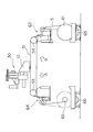
- FIG. 1 is a schematic front view of an inkjet image recording apparatus according to the present invention
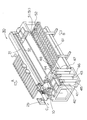
- FIG. 2 is a perspective view thereof.
- a long or plate-shaped recording material S is moved in the sub-scanning direction indicated by a symbol A or B in FIGS. 1 and 2, and the recording head 10 is moved by a recording head moving mechanism 30.
- FIG. 2 an image is recorded on the recording material S by moving in the main scanning direction orthogonal to the sub-scanning direction indicated by reference numeral C. 1 and 2 show a state in which an image is recorded on a long and roll-shaped recording material S.
- a porous (so-called mesh material) endless belt 51 is wound around a pair of rollers 53 and 54.
- the pair of rollers 53 and 54 and the endless belt 51 constitute a belt transport mechanism.
- the endless belt 51 has an upper traveling portion and a lower traveling portion.
- the surface of the upper traveling portion that contacts the recording material S can suck and hold the recording material S by a suction mechanism (not shown).
- the roller 53 is a driving roller
- the roller 54 is a driven roller. Since the motor 53 that can be rotated in forward and reverse directions, which will be described later, is connected to the roller 53, the upper traveling portion of the endless belt 51 can be moved in either the arrow A direction or the arrow B direction.
- the recording material S is unwound from the first roller 61 that rotates by driving the motor 65, and moves while being adsorbed and held on the upper traveling portion of the porous endless belt 51 via the tension adjustment mechanism 63. Then, the recording material S is taken up by a second roller 62 that rotates by driving of a motor 66 via a tension adjusting mechanism 64. In this case, the recording material S moves in the direction of arrow A shown in FIGS.
- the recording material S is unwound from the second roller 62 and is passed through the tension adjusting mechanism 64 to the porous endless belt 51. Move while adsorbed and held. Then, the recording material S is wound around the first roller 61 via the tension adjustment mechanism 63. In this case, the recording material S moves in the direction of arrow B shown in FIGS.
- the auxiliary table 52 shown in FIG. 2 is used when these recording materials are sucked and held on the endless belt 51.
- the auxiliary table 52 is adjusted so that the upper surface height thereof is positioned on the same plane as the upper traveling portion of the endless belt 51.
- the roller 53 is a driving roller, and a motor 55 that can be rotated in forward and reverse directions is connected to the roller 53, so that the driving force of the motor 55 is used to attract the endless belt 51.
- the held hard plate-like recording material or a recording material called a sheet can be moved in the sub-scanning direction.
- the inkjet image recording apparatus includes a touch panel type input / output unit 25. Data necessary for image recording by the ink jet image recording apparatus is input via the input / output unit 25 and displayed.
- this inkjet image recording apparatus performs multicolor printing using yellow, magenta, cyan, black, light cyan, light magenta and white ink.
- the inkjet image recording apparatus includes a yellow ink tank 44, a magenta ink tank 43, a cyan ink tank 42, a black ink tank 41, a light cyan ink tank 46, and a light magenta ink tank 45. And a white ink tank 47 and a cleaning liquid tank 48.
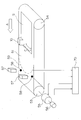
- FIG. 3 is an explanatory view showing a recording material conveyance operation in the belt conveyance mechanism.
- FIG. 3 shows the case where a plate-shaped recording material S is used.
- arrow A indicates the moving direction of the endless belt 51
- symbol C indicates the moving direction of the recording head 10.
- the endless belt 51 has a belt seam 59.
- the mesh material as the belt member is joined with a thin wire or the like so as to be endless
- the seam 59 is joined linearly along the straight end portion of the mesh material.
- the endless belt 51 is mounted on the pair of rollers 53 and 54 and rotated, the shape of the seam 59 is deformed into a U shape, and then the shape is stabilized. Therefore, in FIG. 3, the shape of the joint 59 is shown in a U shape.
- the endless belt 51 has a marker 58 serving as a mark as a start point and an end point for one turn of the moving endless belt 51 at a position on the side of the traveling direction indicated by an arrow A in the vicinity of the joint 59. Yes.
- the markers 58 are formed at two locations near both ends in the main scanning direction on the endless belt 51, which is in a fixed positional relationship with the joint 59.
- the inkjet image recording apparatus includes a motor 55 for driving the roller 53, an encoder 56 for measuring the rotation amount of the roller 53, a position sensor 57 for detecting the marker 58, and a control unit 70.
- the control unit 70 includes a CPU that executes logical operations, a ROM that stores control programs, and a RAM that stores image data and the like, and controls the entire apparatus. And this control part 70 is connected with the motor 55, the encoder 56, and the position sensor 57, as shown in FIG.
- the position sensor 57 is disposed at two positions above the endless belt 51 so that the marker 58 passes immediately below when the endless belt 51 moves.
- the position sensor 57 detects the marker 58, the signal is transmitted to the control unit 70.
- the encoder 56 is connected to the motor 55, and indirectly measures the rotation amount of the roller 53 connected to the motor 55 by measuring the actual driving amount of the motor 55. The value measured by the encoder 56 is transmitted to the control unit 70.
- the control unit 70 that has received signals from the encoder 56 and the position sensor 57 creates a drive signal for the motor 55 based on these signals, and the drive signal is transmitted to the motor 55.
- the endless belt 51 when recording an image, the endless belt 51 is stopped when the recording head 10 is moving above the printing material S in the main scanning direction. It is. Each time the recording head 10 moves once in the main scanning direction, the roller 53 is rotated by a predetermined amount to move the endless belt 51. By repeating the stop and movement of the endless belt 51, the belt transport mechanism feeds the recording material S in the direction indicated by the arrow A.
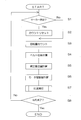
- FIG. 4 is a flowchart showing a correction method of the belt conveyance mechanism according to the present invention.
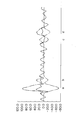
- FIG. 5 is a graph for explaining the relationship between the conveyance error of the endless belt and the correction amount, and
- FIG. 6 is an explanatory diagram showing an example of the correction conveyance amount calculation of the endless belt 51.
- Step S1 the pulse count from the encoder 56 is once reset.
- the marker 58 serves as a mark as a start point and an end point for one turn of the endless belt 51. For this reason, by resetting the pulse count from the encoder 56, the zero point of the start point for one rotation of the endless belt 51 is performed at the position of the marker 58.
- the position sensor 57 does not detect the marker 58, the count of the encoder 56 is integrated without being reset.
- step S2 When the pulse count of the encoder 56 is reset (step S2), the pulse count is started again from there (step S3). Since the encoder 56 is connected to the roller 53 via the motor 55, the control unit 70 stores the signal received from the encoder 56 as a count of the rotation amount of the roller 53. Then, the moving distance of the marker 58, that is, the belt position of the endless belt 51 starting from the marker 58 is calculated from the rotation amount of the roller 53 (step S4).
- an error generation region in which a conveyance error caused by an endless belt, which will be described later, occurs is associated with a belt position, and a conveyance correction amount for correcting the conveyance error based on the conveyance error, which will be described later, is added.
- the corrected transport amount of the endless belt 51 is calculated (step S5).
- the error generation area and the conveyance correction amount are determined by the following procedure.
- the printing paper S is disposed at a predetermined position upstream from the marker 58 with respect to the moving direction of the endless belt 51 (direction of arrow A).
- a test pattern for measuring printing unevenness is printed on the printing paper S.
- the predetermined position means that the recording head 10 is in a position where the joint 59 of the endless belt 51 is in contact with the roller 53 and / or the roller 54 and is separated from the roller 53 and / or the roller 54. This is the position where the test pattern is printed on the printing paper S.
- the test pattern printed in this way is observed with a microscope or the like, and the conveyance error of the endless belt 51 that appears as printing unevenness is measured.
- This ink jet image recording apparatus repeats the operation of rotating the roller 53 by a predetermined amount and moving the endless belt 51 by a predetermined amount every time the recording head 10 moves once in the main scanning direction. For this reason, the length between the preset movement amount (movement distance) of the endless belt 51 and the width in the sub-scanning direction of the image formed by one movement of the recording head 10 in the main scanning direction in the test pattern. The difference in height is taken as a transport error.
- This conveyance error can be represented as a waveform indicated by a one-dot chain line in the graph of FIG. In FIG. 5, the vertical axis indicates the transport error and the transport correction amount ( ⁇ m), and the horizontal axis indicates the position on the endless belt 51 starting from the position of the marker 58.
- the region of the endless belt 51 having a large conveyance error is defined as an error generation region.
- symbol a in FIG. 5 indicates that when the endless belt 51 moves and the seam 59 moves from the upper travel part to the lower travel part, the seam 59 comes into contact with the upper end of the roller 53 that is a driving roller.
- An area b is shown, and symbol b indicates an area when the seam 59 moves away from the lower end of the roller 53 after moving along with the rotation of the roller 53.
- the error generation region is the endless belt 51 in which the joint 59 of the belt member of the endless belt 51 is in contact with or separated from either of the pair of rollers 53, 54. It is also an area including the position of. If the relationship between the error occurrence area and its cause is known, test pattern printing can be performed within the range where the test pattern of the error occurrence area can be obtained, so that it is possible to save printing paper and ink and shorten the information processing time. .
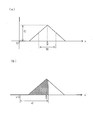
- the conveyance correction amount in the error occurrence area is determined by determining a correction function F (x) for the conveyance errors graphed in FIG. It is calculated
- FIG. 6A shows an example of the correction function F (x)
- FIG. 6B shows the conveyance correction amount obtained by using the correction function F (x). It is schematically shown so that the relationship between the height and the width of the mountain can be understood.
- the vertical axis indicates the transport error and the transport correction amount ( ⁇ m)
- the horizontal axis indicates the position on the endless belt 51 in the sub-scanning direction starting from the position of the marker 58. ing.
- the correction position X is extracted from the graph shown by the one-dot chain line in FIG. As shown in FIG. 6A, the correction position X is the position where the peak height of the graph is the highest when the value in the error occurrence region is a positive value. Further, the correction position X is a median of a correction range that is a region that needs to be corrected, that is, a peak width of the graph, when the peak shape of the graph in the error occurrence region is a normal distribution.
- the correction function F (x) when x is greater than or equal to XW and smaller than X is expressed by the following equation (1).
- the correction function is separately applied when x is in the range before the peak correction position X in the graph shown in FIG. Stand up. As shown by hatching in FIG. 6B, this is because the conveyance amount d for one end of the endless belt 51 corresponding to one movement of the recording head 10 does not include the entire correction range, that is, the correction range. This is to cope with the case where the sheet is divided into two or more conveyances.
- the correction position X, the correction amount C, and the half-value width W of the correction range are values obtained from the conveyance error obtained from the printed test pattern, but when the test pattern is printed a plurality of times, It is determined by a statistical method from the shape and width of the peak of the transport error graphed instead of the average value thereof.
- the individual peaks are described above.
- the transport amount after correction can be obtained.
- the calculation formulas for the correction function F (x) and the correction transport amount described above are not limited to this, and any of a sine function, a cosine function, another linear function, and a nonlinear function can be applied.
- the corrected transport amount obtained for the error occurrence region using the above-described formula is represented by a graph indicated by a two-dot chain line in FIG. Looking at the positions indicated by the symbols a, b, c, and d, the correction amount (value on the vertical axis in the graph of FIG. 5) in the corrected conveyance amount may be substantially opposite in phase to the conveyance error before correction. I understand.
- step S5 based on the corrected transport amount obtained in step S5, the drive amount of the motor 55 connected to the roller 53 that is the drive roller is calculated (step S6). Thereafter, printing is performed while driving the motor 55 according to the obtained driving amount of the motor 55 (step S7). When printing is completed (step S8), correction of the belt conveyance mechanism is also completed.
- the actual transport amount and transport error of the endless belt 51 after the correction of the belt transport mechanism is indicated by a solid line waveform in the graph of FIG. From this, it can be seen that the amplitude of the waveform of the conveyance error is within an allowable range where printing unevenness is not noticeable by the correction of the belt conveyance mechanism described above.
- FIG. 7 is an explanatory diagram for explaining a recording material conveyance operation in a belt conveyance mechanism according to another embodiment.
- the same components as those in the above-described embodiment are denoted by the same reference numerals, and detailed description thereof is omitted.
- an endless belt 91 having a scale along the moving direction is provided at an end portion in the main scanning direction, and an imaging unit 81 that images the scale is further provided.
- the endless belt 91 is graduated, and not according to the printed test pattern, but the scale is monitored by the imaging unit 81 during actual image printing, and is prepared according to the corrected conveyance amount. It becomes possible to verify the effect of the correction on the driving amount of the motor.
Landscapes
- Handling Of Sheets (AREA)
- Ink Jet (AREA)
- Delivering By Means Of Belts And Rollers (AREA)
- Advancing Webs (AREA)
Priority Applications (1)
| Application Number | Priority Date | Filing Date | Title |
|---|---|---|---|
| US13/499,178 US8641165B2 (en) | 2009-09-29 | 2010-06-22 | Inkjet image recorder and method for correction of belt conveyance |
Applications Claiming Priority (2)
| Application Number | Priority Date | Filing Date | Title |
|---|---|---|---|
| JP2009-223579 | 2009-09-29 | ||
| JP2009223579A JP5323631B2 (ja) | 2009-09-29 | 2009-09-29 | インクジェット画像記録装置およびベルト搬送補正方法 |
Publications (1)
| Publication Number | Publication Date |
|---|---|
| WO2011040098A1 true WO2011040098A1 (ja) | 2011-04-07 |
Family
ID=43825933
Family Applications (1)
| Application Number | Title | Priority Date | Filing Date |
|---|---|---|---|
| PCT/JP2010/060526 Ceased WO2011040098A1 (ja) | 2009-09-29 | 2010-06-22 | インクジェット画像記録装置およびベルト搬送補正方法 |
Country Status (3)
| Country | Link |
|---|---|
| US (1) | US8641165B2 (enExample) |
| JP (1) | JP5323631B2 (enExample) |
| WO (1) | WO2011040098A1 (enExample) |
Cited By (1)
| Publication number | Priority date | Publication date | Assignee | Title |
|---|---|---|---|---|
| CN106671596A (zh) * | 2015-07-10 | 2017-05-17 | 精工爱普生株式会社 | 印刷装置 |
Families Citing this family (10)
| Publication number | Priority date | Publication date | Assignee | Title |
|---|---|---|---|---|
| JP5970694B2 (ja) * | 2012-03-16 | 2016-08-17 | セイコーエプソン株式会社 | 液体噴射装置 |
| JP6282393B2 (ja) | 2012-07-27 | 2018-02-21 | 株式会社リコー | 画像形成装置 |
| JP2014159152A (ja) | 2013-01-25 | 2014-09-04 | Seiko Epson Corp | 記録装置及び記録方法 |
| JP2017024206A (ja) * | 2015-07-17 | 2017-02-02 | セイコーエプソン株式会社 | 印刷装置 |
| JP6705140B2 (ja) * | 2015-09-11 | 2020-06-03 | セイコーエプソン株式会社 | 印刷装置 |
| JP2017185694A (ja) * | 2016-04-06 | 2017-10-12 | セイコーエプソン株式会社 | 記録装置及び搬送ベルトの移動量の算出方法 |
| JP6808435B2 (ja) * | 2016-10-11 | 2021-01-06 | 株式会社ミマキエンジニアリング | 印刷装置 |
| JP6948133B2 (ja) | 2017-03-13 | 2021-10-13 | キヤノン株式会社 | 液吸収装置、記録装置、記録方法および製造方法 |
| JP7114961B2 (ja) * | 2018-03-19 | 2022-08-09 | セイコーエプソン株式会社 | 印刷装置及び媒体の搬送方法 |
| DE102018113631A1 (de) * | 2018-06-07 | 2019-12-12 | Windmöller & Hölscher Kg | Transportvorrichtung |
Citations (5)
| Publication number | Priority date | Publication date | Assignee | Title |
|---|---|---|---|---|
| JPS62242964A (ja) * | 1986-04-15 | 1987-10-23 | Canon Inc | 画像形成装置 |
| JPH052347A (ja) * | 1990-10-12 | 1993-01-08 | Canon Inc | 画像形成装置 |
| JP2006235560A (ja) * | 2005-01-25 | 2006-09-07 | Ricoh Co Ltd | ベルト駆動制御装置、色ずれ検出方法、色ずれ検出装置及び画像形成装置 |
| JP2007168174A (ja) * | 2005-12-20 | 2007-07-05 | Fuji Xerox Co Ltd | 液滴吐出装置 |
| JP2009086653A (ja) * | 2007-09-13 | 2009-04-23 | Ricoh Co Ltd | 画像形成装置及びベルト装置 |
Family Cites Families (6)
| Publication number | Priority date | Publication date | Assignee | Title |
|---|---|---|---|---|
| JPH10231041A (ja) * | 1997-02-19 | 1998-09-02 | Fuji Xerox Co Ltd | ベルト蛇行制御装置および画像形成装置 |
| US6557991B2 (en) * | 2000-06-21 | 2003-05-06 | Canon Kabushiki Kaisha | Ink jet recording apparatus and printing method thereof |
| JP3988996B2 (ja) | 2003-03-17 | 2007-10-10 | 株式会社リコー | 画像形成装置 |
| JP2006154289A (ja) * | 2004-11-29 | 2006-06-15 | Ricoh Co Ltd | ベルト搬送装置及び画像形成装置 |
| JP2006306538A (ja) | 2005-04-26 | 2006-11-09 | Canon Inc | シート給送装置及び画像形成装置並びに画像読取装置 |
| JP5546288B2 (ja) * | 2010-02-26 | 2014-07-09 | キヤノン株式会社 | シート厚検出装置、画像形成装置およびシート給送装置 |
-
2009
- 2009-09-29 JP JP2009223579A patent/JP5323631B2/ja active Active
-
2010
- 2010-06-22 US US13/499,178 patent/US8641165B2/en active Active
- 2010-06-22 WO PCT/JP2010/060526 patent/WO2011040098A1/ja not_active Ceased
Patent Citations (5)
| Publication number | Priority date | Publication date | Assignee | Title |
|---|---|---|---|---|
| JPS62242964A (ja) * | 1986-04-15 | 1987-10-23 | Canon Inc | 画像形成装置 |
| JPH052347A (ja) * | 1990-10-12 | 1993-01-08 | Canon Inc | 画像形成装置 |
| JP2006235560A (ja) * | 2005-01-25 | 2006-09-07 | Ricoh Co Ltd | ベルト駆動制御装置、色ずれ検出方法、色ずれ検出装置及び画像形成装置 |
| JP2007168174A (ja) * | 2005-12-20 | 2007-07-05 | Fuji Xerox Co Ltd | 液滴吐出装置 |
| JP2009086653A (ja) * | 2007-09-13 | 2009-04-23 | Ricoh Co Ltd | 画像形成装置及びベルト装置 |
Cited By (1)
| Publication number | Priority date | Publication date | Assignee | Title |
|---|---|---|---|---|
| CN106671596A (zh) * | 2015-07-10 | 2017-05-17 | 精工爱普生株式会社 | 印刷装置 |
Also Published As
| Publication number | Publication date |
|---|---|
| JP2011073143A (ja) | 2011-04-14 |
| JP5323631B2 (ja) | 2013-10-23 |
| US8641165B2 (en) | 2014-02-04 |
| US20120182347A1 (en) | 2012-07-19 |
Similar Documents
| Publication | Publication Date | Title |
|---|---|---|
| JP5323631B2 (ja) | インクジェット画像記録装置およびベルト搬送補正方法 | |
| JP2011073143A5 (enExample) | ||
| JP6417858B2 (ja) | 記録装置及び記録装置の制御方法 | |
| EP2279872A1 (en) | Paper skew detection system | |
| JP7109321B2 (ja) | 印刷装置 | |
| JP2010149377A (ja) | 記録位置補正装置、記録位置補正装置の制御方法、及び記録装置 | |
| JP6437829B2 (ja) | 印刷位置補正方法及びそれを用いた印刷装置 | |
| US20050024413A1 (en) | Media-position media sensor | |
| EP3689627B1 (en) | Method for determining working gap, and recording device | |
| EP3017959A1 (en) | Paper position detector | |
| JP5928098B2 (ja) | 電気的装置及び設定方法 | |
| WO2017086106A1 (ja) | ウェブ搬送装置 | |
| JP2011067991A (ja) | 画像記録装置及び吐出タイミング調整方法 | |
| JP2012088914A (ja) | 印刷装置の製造方法、印刷装置の調整方法、及び、印刷装置 | |
| JP5239992B2 (ja) | 記録装置における搬送誤差補正方法 | |
| JP6562000B2 (ja) | 搬送ベルトの張力調整方法、搬送装置及びインクジェット記録装置 | |
| JP2015182364A (ja) | 検査用チャート及び印刷装置 | |
| JP6151595B2 (ja) | インクジェット印刷装置及びその段差ずれ補正方法 | |
| JP2011042088A (ja) | プリンタ及びプリンタの制御方法 | |
| JP2008028737A (ja) | 媒体上のパターンの印刷位置の算出方法 | |
| US7543905B2 (en) | Method for automatic pen alignment in a printing apparatus | |
| WO2014005608A1 (en) | Inkjet printer | |
| JP2010137990A (ja) | 搬送位置補正装置、搬送位置補正装置の制御方法、及び記録装置 | |
| JP2009234023A (ja) | ローラ偏芯度評価方法とこの方法を実施するプリント装置 | |
| JP4811029B2 (ja) | 印刷方法、画像形成装置および印刷制御プログラム |
Legal Events
| Date | Code | Title | Description |
|---|---|---|---|
| 121 | Ep: the epo has been informed by wipo that ep was designated in this application |
Ref document number: 10820218 Country of ref document: EP Kind code of ref document: A1 |
|
| NENP | Non-entry into the national phase |
Ref country code: DE |
|
| WWE | Wipo information: entry into national phase |
Ref document number: 13499178 Country of ref document: US |
|
| 122 | Ep: pct application non-entry in european phase |
Ref document number: 10820218 Country of ref document: EP Kind code of ref document: A1 |