WO2011030634A1 - 成形部品セット - Google Patents
成形部品セット Download PDFInfo
- Publication number
- WO2011030634A1 WO2011030634A1 PCT/JP2010/063045 JP2010063045W WO2011030634A1 WO 2011030634 A1 WO2011030634 A1 WO 2011030634A1 JP 2010063045 W JP2010063045 W JP 2010063045W WO 2011030634 A1 WO2011030634 A1 WO 2011030634A1
- Authority
- WO
- WIPO (PCT)
- Prior art keywords
- mold
- die
- movable
- semi
- fixed
- Prior art date
- Legal status (The legal status is an assumption and is not a legal conclusion. Google has not performed a legal analysis and makes no representation as to the accuracy of the status listed.)
- Ceased
Links
Images







Classifications
-
- B—PERFORMING OPERATIONS; TRANSPORTING
- B22—CASTING; POWDER METALLURGY
- B22D—CASTING OF METALS; CASTING OF OTHER SUBSTANCES BY THE SAME PROCESSES OR DEVICES
- B22D17/00—Pressure die casting or injection die casting, i.e. casting in which the metal is forced into a mould under high pressure
- B22D17/20—Accessories: Details
- B22D17/22—Dies; Die plates; Die supports; Cooling equipment for dies; Accessories for loosening and ejecting castings from dies
-
- B—PERFORMING OPERATIONS; TRANSPORTING
- B22—CASTING; POWDER METALLURGY
- B22C—FOUNDRY MOULDING
- B22C9/00—Moulds or cores; Moulding processes
- B22C9/06—Permanent moulds for shaped castings
- B22C9/061—Materials which make up the mould
Definitions
- the present invention relates to a molded part set.
- a mold formed from a tungsten-based alloy or a molybdenum-based alloy is known as a casting mold.
- Patent Document 1 Japanese Patent Laid-Open No. 7-232254
- Patent Document 2 Japanese Patent Laid-Open No. 2001-179420
- Patent Document 3 Japanese Patent Laid-Open No. 2004-352584
- Patent Document 4 Japanese Patent Laid-Open No. 6-262066
- An object of the present invention is to extend the life of a mold formed from a tungsten-based alloy or a molybdenum-based alloy.
- the molded part set according to the first invention includes a first mold, a second mold, and an outer peripheral part.
- the first mold is formed of a tungsten base alloy or a molybdenum base alloy.
- the second mold is formed from a tungsten-based alloy or a molybdenum-based alloy.
- die is arrange
- the “predetermined gap” needs to be a gap that does not cause burrs or burr in the molded product.
- the “predetermined temperature” and the “predetermined gap” here are appropriately set according to the type and temperature of the material supplied to the cavity formed by the first mold and the second mold. For this reason, if this molded component set is used, a cavity can be formed by the first mold and the second mold without bringing the first mold and the second mold into contact with each other. Therefore, if this molded part set is used, the lifetime of the metal mold
- the molded part set according to the second invention is the molded part set according to the first invention, wherein the cavity formed by the first mold and the second mold has a semi-molten or semi-solid state iron-based material. Metal is supplied.
- the predetermined gap is 0.05 mm or less at 200 ° C. to 300 ° C.
- the lower limit of the predetermined gap is a value larger than zero.
- flash and a burr will not arise in a clearance gap.
- the molded part set according to the third invention is the molded part set according to the first invention or the second invention, and the outer peripheral part is composed of a block body and a plate body. And a plate body is arrange
- a die cast molding apparatus (hereinafter referred to as “molding apparatus”) 1 according to the present embodiment, a preform of an iron-based part, for example, a preform of a movable scroll of a scroll compressor, that is, shown in FIGS.
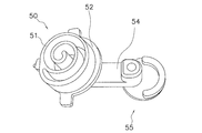
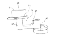
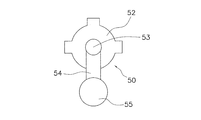
- the end plate equivalent portion 52 As shown, the end plate equivalent portion 52, a spiral wrap equivalent portion 51 extending from one plate surface of the end plate equivalent portion 52 in a direction substantially perpendicular to the plate surface, and the opposite side of the end plate equivalent portion 52 on the wrap equivalent portion side.
- the molding apparatus 1 mainly includes a die-cast mold (hereinafter referred to as “mold”) 2, a wrap push pin 3, a billet insertion mechanism 6, and a push pin drive mechanism 7. .
- a semi-molten iron billet or a semi-solid iron material (hereinafter referred to as “semi-molten / semi-solid metal material”) C is pressed into the mold 2 by the billet insertion mechanism 6.
- the scroll member preform 50 is die-cast.
- the movable mold 11 is slid rearward (see the white arrow Db in FIG. 1) and pulled away from the fixed mold 12 (see FIG. 14).
- the wrap push pin 3 and the auxiliary push pin 9 are pushed into the movable die 11 by the push pin driving mechanism 7, so that the preform of the scroll member is formed from the movable die 11. 50 is taken out (see FIG. 15).
- the mold 2 and the wrap extrusion pin 3 will be described in more detail as separate items.
- the mold 2 mainly includes a movable mold 11 that can reciprocate in the horizontal direction, a fixed mold 12 that is fixed to a table (not shown), a slide core 5, and lap extrusion. It comprises a pin 3 and an auxiliary push pin 9.
- the movable die 11 mainly includes a movable side main die 111, a movable side nest 112, a movable side pressure plate 113, and a movable side core 114. And a movable side chill vent 115. As shown in FIGS.
- the movable side main mold 111 is a frame for housing the movable side core 114, the movable side insert 112, the movable side pressure plate 113, and the movable side chill vent 115. It is. As shown in FIGS. 1, 5, and 6, the movable side main mold 111 is fixed to the movable side platen 21, and approaches the fixed mold 12 together with the movable platen 21 (open arrow Df in FIG. 1). And it can reciprocate in the direction away from the fixed mold 12 (see the white arrow Db in FIG. 1).
- the movable side insert 112 is a member disposed inside the movable side main mold 111 and outside the movable side core 114, and the movable side core 114 is located at a specified position.
- the movable side core 114 is supported so as to fit within the range.
- the movable side pressure plate 113 is a plate-like member disposed above and below the movable side nest 112, and when the movable mold 11 is fitted to the fixed mold 12 and clamped. Receiving clamping force.
- the movable receiving pressure plate 113 is placed between the movable core 114 and the fixed core 124 (described later) when contacting the fixed receiving pressure plate 123 (described later) at a temperature of 200 to 300 ° C. It is designed so that a gap of 0.05 mm or less is generated.
- the movable core 114 is a mold formed of a tungsten base alloy or a molybdenum base alloy. Examples of the tungsten-based alloy include sintered superpolymerized gold heavy metals HM-1, HM-2, HM-5, HM-7, HM-7S, HM-7ST, HM-8, manufactured by Allied Material Co., Ltd. Examples thereof include HM-8ST and HM-185. In addition, as shown in FIGS.
- the movable core 114 has a spiral groove 13 a for forming a wrap equivalent portion 51 of the preform 50 of the scroll member, and an end plate equivalent portion. A recess 13b for forming 52 is formed.
- the movable core 114 is also formed with a plurality of vent grooves that communicate with the spiral groove 13a and extend to the movable chill vent 115.
- the movable chill vent 115 cools the semi-molten or semi-solid state metal flowing from the vent groove.
- the movable side chill vent 115 also serves to discharge the air in the cavity 13 pushed out when the semi-molten / semi-solidified metal material C is inserted to the outside.
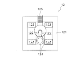
- the fixed mold 12 is mainly composed of a fixed main mold 121, a fixed insert 122, a fixed receiving pressure plate 123, and a fixed core 124 as shown in FIGS. And a fixed-side chill vent 125.
- the fixed-side main mold 121 is a frame for housing the fixed-side core 124, the fixed-side insert 122, the fixed-side receiving pressure plate 123, and the fixed-side chill vent 125. It is.
- the stationary main mold 121 is fixed to the stationary platen 22 and is always stationary.
- the fixed-side insert 122 is a member disposed inside the fixed-side main mold 121 and outside the fixed-side core 124, and the fixed-side insert 124 is located at a predetermined position.
- the movable side core 114 is supported so as to fit within the range.
- the fixed-side pressure plate 123 is a plate-like member disposed above and below the fixed-side insert 122, and when the fixed mold 12 is coupled to the movable mold 11 and connected. Receives connection pressure.
- the fixed side pressure plate 123 has a gap of 0.05 mm or less between the fixed side core 124 and the movable side core 114 when it contacts the movable side pressure plate 113 at a temperature of 200 to 300 ° C.
- the stationary core 124 is a mold formed of a tungsten base alloy or a molybdenum base alloy.
- the tungsten-based alloy include sintered superpolymerized gold heavy metals HM-1, HM-2, HM-5, HM-7, HM-7S, HM-7ST, HM-8, manufactured by Allied Material Co., Ltd. Examples thereof include HM-8ST and HM-185.
- the fixed-side core 124 has a cylindrical groove 13c for forming a columnar boss equivalent portion 53 and a runner for forming a runner 54, as shown in FIGS. A groove 13d and an insertion recess 13e into which the slide core 5 is inserted are formed.
- the fixed-side chill vent 125 cools the semi-molten or semi-solid state metal flowing from the vent groove formed in the movable core 114.
- the fixed side chill vent 125 also serves to discharge the air in the cavity 13 pushed out when the semi-molten / semi-solidified metal material C is inserted to the outside.
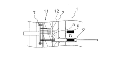
- the slide core 5 is two cores provided so as to oppose each other to the movable mold 11, and includes the movable mold 11 and the fixed mold 12.
- Runner groove 13d which is a flow path for inserting the semi-molten / semi-solidified metal material C into the cavity 13, is formed in the shape of the scroll member preform 50 formed when the mold is clamped. In order to do so, it is slid into the cavity 13.
- the wrap extrusion pin 3 is driven by an extrusion pin so that it can pass through a through hole 15 formed in the movable mold 11 and can appear and disappear at the tip of the spiral groove 13 a of the cavity 13. It is attached to the mechanism 7.
- the wrap pusher pin 3 pushes the tip 51a of the wrap-corresponding portion 51 of the scroll member preform 50 after molding the scroll member preform 50, thereby pushing the scroll member preform 50 out of the movable die 11. be able to.
- Auxiliary Extrusion Pin As shown in FIG.
- the auxiliary extrusion pin 9 is extruded through the through hole 16 formed in the movable mold 11 so that the auxiliary extrusion pin 9 can appear and disappear on the side surface of the runner groove 13d on the billet insertion mechanism side. It is attached to the pin drive mechanism 7.
- the auxiliary push pin 9 can push the scroll member preform 50 from the movable die 11 by pressing the side surface of the runner 54 on the billet insertion mechanism side after the scroll member preform 50 is formed.
- the preform 50 of the scroll member formed in the present embodiment is a movable scroll preform, and this preform has a columnar boss equivalent portion 53 as shown in FIGS. Exists.
- the semi-molten / semi-solidified metal material C when the semi-molten / semi-solidified metal material C is inserted into the cavity 13, the semi-molten / semi-solid metal material C corresponds to the boss equivalent portion 53 after passing through the runner groove 13d.
- the cavity 13 is filled so as to flow from the cavity portion toward the cavity portion corresponding to the wrap equivalent portion 51.
- one end of the runner 54 after molding is connected to the boss equivalent portion 53.
- the runner 54 is removed after being removed from the mold 2.
- the billet insertion mechanism 6 is located directly behind the boss equivalent portion 53 in order to remove the surface scale of the semi-molten / semi-solidified metal material C immediately after coming out of the billet insertion mechanism 6.
- the runner grooves 13d are spaced apart. For this reason, since the surface scale of the semi-molten / semi-solidified metal material C mainly accumulates on the billet insertion mechanism side portion of the runner 54, the scale is less mixed into the preform 50 of the scroll member.
- the movable mold 11 is moved toward the fixed mold 12, and the movable mold 11 and the fixed mold 12 are clamped to form the cavity 13. At this time, a gap of 0.05 mm or less is generated on the opposing surfaces of the cores 114 and 124 by the pressure receiving plates 113 and 123.
- the semi-molten / semi-solid metal material C is put into the billet insertion mechanism 6.
- the billet filling step as shown in FIG. 12
- hydraulic pressure or air pressure is applied to the plunger 6a of the billet insertion mechanism 6 to push in the plunger 6a, and the semi-molten / semi-solidified metal material C applies pressure.
- the mold 2 is filled in the added state.
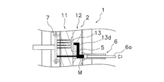
- the semi-molten / semi-solidified metal material C is filled into the cavity 13 through the runner groove 13d.
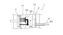
- the preform 50 of the scroll member also includes a runner 54 formed inside the runner groove 13d as shown in FIGS.
- the movable mold 11 is slid backward, the movable mold 11 is separated from the fixed mold 12, and the mold 2 is opened.
- the slide core 5 moves toward the movable mold 11 while being sandwiched between the preform 50 of the scroll member and the runner 54.
- the plunger 6a of the billet insertion mechanism 6 is slightly pushed out so that the scroll member preform 50 can be easily separated from the fixed mold 12.
- the slide core 5 is returned to the initial position. That is, in this step, the two slide cores 5 are separated from each other, and the preform 50 of the scroll member can be taken out.
- the extruding pin driving mechanism 7 is driven so that the lapping extruding pin 3 and the auxiliary extruding pin 9 are inside the spiral groove 13a of the movable die 11 and the billet insertion mechanism of the runner groove 13d. It is made to protrude in the side part, and the preforming body 50 of a scroll member is extruded. The plunger 6a is returned to the initial position after the extrusion of the scroll member preform 50 is completed. Finally, in the preforming body taking-out step, as shown in FIG. 16, the scroll member preforming body 50 is taken out from the molding die 2.
- the lap push pin 3 and the auxiliary push pin 9 are returned to the initial state (see FIG. 9).
- the preform 50 of the scroll member is cut at a boundary portion between the runner 54 and the boss equivalent portion 53.
- the preform 50 of the scroll member is then machined into a scroll member (finished product).
- a 0.05 mm gap is formed between the fixed side core 124 and the movable side core 114.
- the cavity 13 can be formed by the fixed side core 124 and the movable side core 114 without bringing the movable side core 114 and the fixed side core 124 into contact with each other.
- flash and a burr will not arise in a preforming body.
- the molding apparatus 1 if the molding apparatus 1 is used, the lifetime of the cores 114 and 124 can be extended. Further, in the molding apparatus 1, the coupling pressure when the molding die is coupled is received by the receiving pressure plates 113 and 123. For this reason, it is not necessary to replace the inserts 112 and 122, and the receiving pressure plates 113 and 123 may be replaced periodically. For this reason, the cost performance of manufacturing the preform 50 can be improved.
- the slide core 5 is used.
- a placement core having a shape in which the slide core is integrated may be used.
- one mold is fixed. However, both molds may be movable.
- the scroll member preform 50 is molded, but other component preforms may be molded.
- connection pressure of the molding die 2 is received by the pressure receiving plates 113 and 123.
- the pressure receiving plates 113 and 123 are omitted and the connection pressure is received by the inserts 112 and 122. It doesn't matter.
- the inserts 112 and 122 are designed so that a gap of 0.05 mm or less is generated between the fixed core 124 and the movable core 114 when they are in contact with each other at a temperature of 200 to 300 ° C. Need to be done.
- the inserts 112 and 122 are arranged.
- the inserts 112 and 122 are omitted, and the main molds 111 and 121 and the cores 114 and 124 constitute the molds 11 and 12. It doesn't matter. In such a case, the main molds 111 and 121 have a gap of 0.05 mm or less between the fixed side core 124 and the movable side core 114 when they come into contact with each other at a temperature of 200 to 300 ° C. Need to be designed.
- the iron-based semi-molten / semi-solid metal M is used as the molding material in the molding apparatus 1 according to the previous embodiment, a metal other than the iron-based semi-melt / semi-solid metal M may be used. Absent. In such a case, the gap between the fixed core 124 and the movable core 114 is appropriately set depending on the type and temperature of the metal.
- the molded part set according to the present invention is characterized in that the life of a mold formed from a tungsten-based alloy or a molybdenum-based alloy can be extended, and a mold formed from a tungsten-based alloy or a molybdenum-based alloy. It is useful for the production of molded products using
Landscapes
- Engineering & Computer Science (AREA)
- Mechanical Engineering (AREA)
- Chemical & Material Sciences (AREA)
- Materials Engineering (AREA)
- Molds, Cores, And Manufacturing Methods Thereof (AREA)
- Rotary Pumps (AREA)
Abstract
成形部品セットは、第1金型、第2金型および外周部品を備える。第1金型は、タングステン基合金またはモリブデン基合金から形成される。第2金型は、タングステン基合金またはモリブデン基合金から形成される。また、この第2金型は、第1金型と対抗するように配置される。外周部品は、少なくとも2つ存在し、所定の温度において第1金型の第2金型に対抗する面と第2金型の第1金型に対抗する面との間に所定の隙間を生じさせるように第1金型および第2金型のそれぞれの外周に対抗して配置される。
Description
本発明は、成形部品セットに関する。
従前から、鋳造用の金型としてタングステン基合金やモリブデン基合金から形成される金型が知られている。例えば、タングステン基合金から形成される金型については特許文献1(特開平7-232254号公報)や、特許文献2(特開2001-179420号公報)、特許文献3(特開2004-352584号公報)に詳しく、モリブデン基合金から形成される金型については特許文献4(特開平6-220566号公報)に詳しい。
ところで、タングステン基合金やモリブデン基合金から成る金型は通常の鉄系の金型に比べて高価であり、成形加工の現場ではタングステン基合金やモリブデン基合金から成る金型の寿命をできるだけ延ばしたいとの要望がある。
本発明の課題は、タングステン基合金やモリブデン基合金から形成される金型の寿命を延ばすことにある。
本発明の課題は、タングステン基合金やモリブデン基合金から形成される金型の寿命を延ばすことにある。
第1発明に係る成形部品セットは、第1金型、第2金型および外周部品を備える。第1金型は、タングステン基合金またはモリブデン基合金から形成される。第2金型は、タングステン基合金またはモリブデン基合金から形成される。また、この第2金型は、第1金型と対抗するように配置される。外周部品は、少なくとも2つ存在し、所定の温度において第1金型の第2金型に対抗する面と第2金型の第1金型に対抗する面との間に所定の隙間を生じさせるように第1金型および第2金型のそれぞれの外周に対抗して配置される。なお、ここにいう「所定の隙間」とは、成形品にバリやかえりが生じない程度の隙間である必要がある。また、ここにいう「所定の温度」および「所定の隙間」は、第1金型と第2金型とによって形成されるキャビティに供給される材料の種類や温度によって適宜設定される。
このため、この成形部品セットを用いれば、第1金型と第2金型とを接触させることなく第1金型と第2金型とによりキャビティを形成することができる。したがって、この成形部品セットを用いれば、タングステン基合金やモリブデン基合金から形成される金型の寿命を延ばすことができる。また、金型間の隙間を、成形品にバリやかえりが生じない程度の隙間とすることができれば、さらにタングステン基合金やモリブデン基合金から形成される金型の寿命を延ばすことができる。
このため、この成形部品セットを用いれば、第1金型と第2金型とを接触させることなく第1金型と第2金型とによりキャビティを形成することができる。したがって、この成形部品セットを用いれば、タングステン基合金やモリブデン基合金から形成される金型の寿命を延ばすことができる。また、金型間の隙間を、成形品にバリやかえりが生じない程度の隙間とすることができれば、さらにタングステン基合金やモリブデン基合金から形成される金型の寿命を延ばすことができる。
第2発明に係る成形部品セットは、第1発明に係る成形部品セットであって、第1金型と第2金型とによって形成されるキャビティには、半溶融状態または半凝固状態の鉄系金属が供給される。そして、このとき、所定の隙間は、200℃~300℃において0.05mm以下である。なお、所定の隙間の下限は当然ながら0より大きい値である。また、この隙間であれば、隙間にバリやかえりが生じない。
本願発明者らが鋭意検討したところ、第1金型と第2金型とによって形成されるキャビティに半溶融状態または半凝固状態の鉄系金属が供給される場合、第1金型と第2金型との間に0.05mm以下の隙間を空けていても問題なくバリやかえりのない成形品を得ることができることが明らかとなった。したがって、この成形部品セットを用いれば、半溶融ダイキャスト成形法または半凝固ダイキャスト成形法により鉄系金属を成形する場合であっても、タングステン基合金やモリブデン基合金から形成される金型の寿命を延ばすことができる。
本願発明者らが鋭意検討したところ、第1金型と第2金型とによって形成されるキャビティに半溶融状態または半凝固状態の鉄系金属が供給される場合、第1金型と第2金型との間に0.05mm以下の隙間を空けていても問題なくバリやかえりのない成形品を得ることができることが明らかとなった。したがって、この成形部品セットを用いれば、半溶融ダイキャスト成形法または半凝固ダイキャスト成形法により鉄系金属を成形する場合であっても、タングステン基合金やモリブデン基合金から形成される金型の寿命を延ばすことができる。
第3発明に係る成形部品セットは、第1発明又は第2発明に係る成形部品セットであって、外周部品は、ブロック体とプレート体とから構成される。そして、プレート体は、互いに対抗するように配置される。
このため、この成形部品セットを用いれば、第1金型と第2金型とによってキャビティを形成したときの型締め力を主にプレート体で受けることができる。したがって、この成形部品セットを用いれば、ブロック体よりも安価なプレート体を定期的に交換することにより、タングステン基合金やモリブデン基合金から形成される金型の寿命を延ばすことができる。よって、この成形部品セットを用いれば、タングステン基合金やモリブデン基合金から形成される金型を利用した成形品製造のコストパフォーマンスを向上させることができる。
このため、この成形部品セットを用いれば、第1金型と第2金型とによってキャビティを形成したときの型締め力を主にプレート体で受けることができる。したがって、この成形部品セットを用いれば、ブロック体よりも安価なプレート体を定期的に交換することにより、タングステン基合金やモリブデン基合金から形成される金型の寿命を延ばすことができる。よって、この成形部品セットを用いれば、タングステン基合金やモリブデン基合金から形成される金型を利用した成形品製造のコストパフォーマンスを向上させることができる。
以下、ダイキャスト成形型2およびそれを備えたダイキャスト成形装置1を、図面を参照しながら説明する。
<ダイキャスト成形装置の構成>
本実施の形態に係るダイキャスト成形装置(以下「成形装置」という)1では、鉄系部品の予備成形体、例えば、スクロール圧縮機の可動スクロールの予備成形体、すなわち、図2~4に示されるように、鏡板相当部分52、鏡板相当部分52の一方の板面から板面の略垂直方向に向かって延びる渦巻き状のラップ相当部分51、および鏡板相当部分52のラップ相当部分側の反対側の板面から略垂直方向に向かって延びる円柱状のボス相当部分53を有するスクロール部材の予備成形体50が成形される。
成形装置1は、図1に示されるように、主に、ダイキャスト成形型(以下「成形型」という)2、ラップ押出ピン3、ビレット挿入機構6および押出ピン駆動機構7から構成されている。
<ダイキャスト成形装置の構成>
本実施の形態に係るダイキャスト成形装置(以下「成形装置」という)1では、鉄系部品の予備成形体、例えば、スクロール圧縮機の可動スクロールの予備成形体、すなわち、図2~4に示されるように、鏡板相当部分52、鏡板相当部分52の一方の板面から板面の略垂直方向に向かって延びる渦巻き状のラップ相当部分51、および鏡板相当部分52のラップ相当部分側の反対側の板面から略垂直方向に向かって延びる円柱状のボス相当部分53を有するスクロール部材の予備成形体50が成形される。
成形装置1は、図1に示されるように、主に、ダイキャスト成形型(以下「成形型」という)2、ラップ押出ピン3、ビレット挿入機構6および押出ピン駆動機構7から構成されている。
この成形装置1では、ビレット挿入機構6によって半溶融状態の鉄系ビレットあるいは半凝固状態の鉄系材料(以下「半溶融・半凝固金属材料」という)Cが成形型2内部に圧力をかけられて挿入されることにより、スクロール部材の予備成形体50がダイキャスト成形される。
なお、スクロール部材の予備成形体50が成形された後、可動型11は、後方(図1の白抜き矢印Db参照)にスライド移動されて固定型12から引き離される(図14参照)。その後、スライド中子5がスライド移動された後、ラップ押出ピン3および補助押出ピン9が押出ピン駆動機構7によって可動型11内部に押し込まれることにより、可動型11内部からスクロール部材の予備成形体50が取り出される(図15参照)。
以下、成形型2およびラップ押出ピン3を別項目としてさらに詳細に説明する。
なお、スクロール部材の予備成形体50が成形された後、可動型11は、後方(図1の白抜き矢印Db参照)にスライド移動されて固定型12から引き離される(図14参照)。その後、スライド中子5がスライド移動された後、ラップ押出ピン3および補助押出ピン9が押出ピン駆動機構7によって可動型11内部に押し込まれることにより、可動型11内部からスクロール部材の予備成形体50が取り出される(図15参照)。
以下、成形型2およびラップ押出ピン3を別項目としてさらに詳細に説明する。
<成形型の構成>
成形型2は、図1に示されるように、主に、水平方向に沿って往復移動可能な可動型11と、図示しない台に固定された固定型12と、スライド中子5と、ラップ押出ピン3と、補助押出ピン9とから構成される。以下、それぞれについて詳述する。
(1)可動型
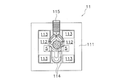
可動型11は、図1、図5および図6に示されるように、主に、可動側主型111、可動側入れ子112、可動側受け圧プレート113、可動側中子114および可動側チルベント115から構成される。
可動側主型111は、図1、図5および図6に示されるように、可動側中子114、可動側入れ子112、可動側受け圧プレート113および可動側チルベント115を収容するための枠体である。可動側主型111は、図1、図5および図6に示されるように、可動側プラテン21に固定されており、可動プラテン21と共に固定型12に近づく方向(図1の白抜き矢印Df)および固定型12から離れる方向(図1の白抜き矢印Db参照)へ往復移動することができる。
成形型2は、図1に示されるように、主に、水平方向に沿って往復移動可能な可動型11と、図示しない台に固定された固定型12と、スライド中子5と、ラップ押出ピン3と、補助押出ピン9とから構成される。以下、それぞれについて詳述する。
(1)可動型
可動型11は、図1、図5および図6に示されるように、主に、可動側主型111、可動側入れ子112、可動側受け圧プレート113、可動側中子114および可動側チルベント115から構成される。
可動側主型111は、図1、図5および図6に示されるように、可動側中子114、可動側入れ子112、可動側受け圧プレート113および可動側チルベント115を収容するための枠体である。可動側主型111は、図1、図5および図6に示されるように、可動側プラテン21に固定されており、可動プラテン21と共に固定型12に近づく方向(図1の白抜き矢印Df)および固定型12から離れる方向(図1の白抜き矢印Db参照)へ往復移動することができる。
可動側入れ子112は、図5および図6に示されるように、可動側主型111の内側、可動側中子114の外側に配置される部材であって、可動側中子114が規定の位置に収まるように可動側中子114を支持している。
可動側受け圧プレート113は、図5および図6に示されるように、可動側入れ子112の上下に配置される板状部材であって、可動型11が固定型12に合わさり型締めされるときに型締め力を受ける。なお、この可動側受け圧プレート113は、200~300℃の温度で固定側受け圧プレート123(後述)と接触したときに可動側中子114と固定側中子124(後述)との間に0.05mm以下の隙間が生じるように設計されている。
可動側中子114は、タングステン基合金またはモリブデン基合金から形成される金型である。なお、タングステン基合金としては、例えば、(株)アライドマテリアル社の焼結超重合金ヘビイメタルHM-1、HM-2、HM-5、HM-7、HM-7S、HM-7ST、HM-8、HM-8ST、HM-185等が挙げられる。そして、この可動側中子114には、図1、図5および図6に示されるように、スクロール部材の予備成形体50のラップ相当部分51を形成するための渦巻き溝13aと、鏡板相当部分52を形成するための凹部13bとが形成されている。また、この可動側中子114には、渦巻き溝13aと連通し可動側チルベント115まで延びる複数のベント溝も形成されている。
可動側チルベント115は、ベント溝から流れてくる半溶融状態又は半凝固状態の金属を冷却する。また、この可動側チルベント115は、半溶融・半凝固金属材料Cが挿入されるときに押し出されるキャビティ13内の空気を外部へ排出する役目も担っている。
可動側受け圧プレート113は、図5および図6に示されるように、可動側入れ子112の上下に配置される板状部材であって、可動型11が固定型12に合わさり型締めされるときに型締め力を受ける。なお、この可動側受け圧プレート113は、200~300℃の温度で固定側受け圧プレート123(後述)と接触したときに可動側中子114と固定側中子124(後述)との間に0.05mm以下の隙間が生じるように設計されている。
可動側中子114は、タングステン基合金またはモリブデン基合金から形成される金型である。なお、タングステン基合金としては、例えば、(株)アライドマテリアル社の焼結超重合金ヘビイメタルHM-1、HM-2、HM-5、HM-7、HM-7S、HM-7ST、HM-8、HM-8ST、HM-185等が挙げられる。そして、この可動側中子114には、図1、図5および図6に示されるように、スクロール部材の予備成形体50のラップ相当部分51を形成するための渦巻き溝13aと、鏡板相当部分52を形成するための凹部13bとが形成されている。また、この可動側中子114には、渦巻き溝13aと連通し可動側チルベント115まで延びる複数のベント溝も形成されている。
可動側チルベント115は、ベント溝から流れてくる半溶融状態又は半凝固状態の金属を冷却する。また、この可動側チルベント115は、半溶融・半凝固金属材料Cが挿入されるときに押し出されるキャビティ13内の空気を外部へ排出する役目も担っている。
(2)固定型
固定型12は、図1、図7および図8に示されるように、主に、固定側主型121、固定側入れ子122、固定側受け圧プレート123、固定側中子124および固定側チルベント125から構成される。
固定側主型121は、図1、図7および図8に示されるように、固定側中子124、固定側入れ子122、固定側受け圧プレート123および固定側チルベント125を収容するための枠体である。固定側主型121は、図1、図7および図8に示されるように、固定プラテン22に固定されており、常に静止している。
固定型12は、図1、図7および図8に示されるように、主に、固定側主型121、固定側入れ子122、固定側受け圧プレート123、固定側中子124および固定側チルベント125から構成される。
固定側主型121は、図1、図7および図8に示されるように、固定側中子124、固定側入れ子122、固定側受け圧プレート123および固定側チルベント125を収容するための枠体である。固定側主型121は、図1、図7および図8に示されるように、固定プラテン22に固定されており、常に静止している。
固定側入れ子122は、図7および図8に示されるように、固定側主型121の内側、固定側中子124の外側に配置される部材であって、固定側中子124が規定の位置に収まるように可動側中子114を支持している。
固定側受け圧プレート123は、図7および図8に示されるように、固定側入れ子122の上下に配置される板状部材であって、固定型12が可動型11に合わさり連結されるときに連結圧を受ける。なお、この固定側受け圧プレート123は、200~300℃の温度で可動側受け圧プレート113と接触したときに固定側中子124と可動側中子114との間に0.05mm以下の隙間が生じるように設計されている。
固定側中子124は、タングステン基合金またはモリブデン基合金から形成される金型である。なお、タングステン基合金としては、例えば、(株)アライドマテリアル社の焼結超重合金ヘビイメタルHM-1、HM-2、HM-5、HM-7、HM-7S、HM-7ST、HM-8、HM-8ST、HM-185等が挙げられる。そして、この固定側中子124には、図1、図7および図8に示されるように、円柱状のボス相当部分53を形成するための円柱溝13cと、ランナー54を形成するためのランナー溝13dと、スライド中子5が挿入される挿入凹部13eが形成されている。
固定側チルベント125は、可動側中子114に形成されるベント溝から流れてくる半溶融状態又は半凝固状態の金属を冷却する。また、この固定側チルベント125は、半溶融・半凝固金属材料Cが挿入されるときに押し出されるキャビティ13内の空気を外部へ排出する役目も担っている。
固定側受け圧プレート123は、図7および図8に示されるように、固定側入れ子122の上下に配置される板状部材であって、固定型12が可動型11に合わさり連結されるときに連結圧を受ける。なお、この固定側受け圧プレート123は、200~300℃の温度で可動側受け圧プレート113と接触したときに固定側中子124と可動側中子114との間に0.05mm以下の隙間が生じるように設計されている。
固定側中子124は、タングステン基合金またはモリブデン基合金から形成される金型である。なお、タングステン基合金としては、例えば、(株)アライドマテリアル社の焼結超重合金ヘビイメタルHM-1、HM-2、HM-5、HM-7、HM-7S、HM-7ST、HM-8、HM-8ST、HM-185等が挙げられる。そして、この固定側中子124には、図1、図7および図8に示されるように、円柱状のボス相当部分53を形成するための円柱溝13cと、ランナー54を形成するためのランナー溝13dと、スライド中子5が挿入される挿入凹部13eが形成されている。
固定側チルベント125は、可動側中子114に形成されるベント溝から流れてくる半溶融状態又は半凝固状態の金属を冷却する。また、この固定側チルベント125は、半溶融・半凝固金属材料Cが挿入されるときに押し出されるキャビティ13内の空気を外部へ排出する役目も担っている。
(3)スライド中子
スライド中子5は、図5および図6に示されるように、可動型11に互いに対抗するようにして設けられる2つの中子であって、可動型11と固定型12とを型締めしたときに形成されるスクロール部材の予備成形体50の形状をした鋳造空間、すなわちキャビティ13に半溶融・半凝固金属材料Cを挿入するための流路であるランナー溝13dを形成するために、キャビティ13内部にスライド挿入される。
スライド中子5は、図5および図6に示されるように、可動型11に互いに対抗するようにして設けられる2つの中子であって、可動型11と固定型12とを型締めしたときに形成されるスクロール部材の予備成形体50の形状をした鋳造空間、すなわちキャビティ13に半溶融・半凝固金属材料Cを挿入するための流路であるランナー溝13dを形成するために、キャビティ13内部にスライド挿入される。
(4)ラップ押出ピン
ラップ押出ピン3は、図1に示されるように、可動型11に形成された貫通孔15を通って、キャビティ13の渦巻き溝13aの先端に出没できるように押出ピン駆動機構7に取り付けられている。そして、このラップ押出ピン3は、スクロール部材の予備成形体50の成形後にスクロール部材の予備成形体50のラップ相当部分51の先端51aを押して、スクロール部材の予備成形体50を可動型11から押し出すことができる。
(5)補助押出ピン
補助押出ピン9は、図1に示されるように、可動型11に形成された貫通孔16を通って、ランナー溝13dのビレット挿入機構側の側面に出没できるように押出ピン駆動機構7に取り付けられている。そして、この補助押出ピン9は、スクロール部材の予備成形体50の成形後にランナー54のビレット挿入機構側の側面を押して、スクロール部材の予備成形体50を可動型11から押し出すことができる。
ラップ押出ピン3は、図1に示されるように、可動型11に形成された貫通孔15を通って、キャビティ13の渦巻き溝13aの先端に出没できるように押出ピン駆動機構7に取り付けられている。そして、このラップ押出ピン3は、スクロール部材の予備成形体50の成形後にスクロール部材の予備成形体50のラップ相当部分51の先端51aを押して、スクロール部材の予備成形体50を可動型11から押し出すことができる。
(5)補助押出ピン
補助押出ピン9は、図1に示されるように、可動型11に形成された貫通孔16を通って、ランナー溝13dのビレット挿入機構側の側面に出没できるように押出ピン駆動機構7に取り付けられている。そして、この補助押出ピン9は、スクロール部材の予備成形体50の成形後にランナー54のビレット挿入機構側の側面を押して、スクロール部材の予備成形体50を可動型11から押し出すことができる。
<ダイキャスト成形法の概要>
本実施の形態において成形されるスクロール部材の予備成形体50は可動スクロールの予備成形体であり、この予備成形体には、図2~4に示されるように、円柱状のボス相当部分53が存在する。そして、本実施の形態では、半溶融・半凝固金属材料Cがキャビティ13に挿入されるとき、半溶融・半凝固金属材料Cは、ランナー溝13dを通った後、ボス相当部分53に対応するキャビティ部分からラップ相当部分51に対応するキャビティ部分へ向って流れるように、キャビティ13に充填される。
なお、成形後のランナー54の一端は、ボス相当部分53と繋がっている。そして、このランナー54は、成形型2から取り出された後に切除される。
また、本実施の形態に係る成形装置1では、ビレット挿入機構6から出た直後の半溶融・半凝固金属材料Cの表面スケールを除去するため、ビレット挿入機構6はボス相当部分53の真後ろに配置されずにランナー溝13dの分だけ離間して配置されている。このため、半溶融・半凝固金属材料Cの表面スケールは、主にランナー54のビレット挿入機構側部分にたまるので、スクロール部材の予備成形体50へのスケールの混入が少なくなる。
本実施の形態において成形されるスクロール部材の予備成形体50は可動スクロールの予備成形体であり、この予備成形体には、図2~4に示されるように、円柱状のボス相当部分53が存在する。そして、本実施の形態では、半溶融・半凝固金属材料Cがキャビティ13に挿入されるとき、半溶融・半凝固金属材料Cは、ランナー溝13dを通った後、ボス相当部分53に対応するキャビティ部分からラップ相当部分51に対応するキャビティ部分へ向って流れるように、キャビティ13に充填される。
なお、成形後のランナー54の一端は、ボス相当部分53と繋がっている。そして、このランナー54は、成形型2から取り出された後に切除される。
また、本実施の形態に係る成形装置1では、ビレット挿入機構6から出た直後の半溶融・半凝固金属材料Cの表面スケールを除去するため、ビレット挿入機構6はボス相当部分53の真後ろに配置されずにランナー溝13dの分だけ離間して配置されている。このため、半溶融・半凝固金属材料Cの表面スケールは、主にランナー54のビレット挿入機構側部分にたまるので、スクロール部材の予備成形体50へのスケールの混入が少なくなる。
<ダイキャスト成形法の手順>
本発明の実施の形態に係るダイキャスト成形法では、初期工程、型締め工程、ビレット挿入工程、ビレット充填工程、型開き工程、スライド中子開放工程、押出し工程、予備成形体取出し工程を経てスクロール部材の予備成形体50が成形される。以下、各工程における成形装置1の状態を図9~16を参照しながら説明する。
先ず、初期工程では、主型111,121、入れ子112,122および中子114,124をすべて合わせた成形型2全体が約200℃まで予備加熱される。
次に、型締め工程では、図10に示されるように、可動型11が固定型12に向かって移動され、可動型11と固定型12とが型締めされてキャビティ13が形成される。なお、このとき、受け圧プレート113,123により中子114,124の対向面に0.05mm以下の隙間が生じている。
本発明の実施の形態に係るダイキャスト成形法では、初期工程、型締め工程、ビレット挿入工程、ビレット充填工程、型開き工程、スライド中子開放工程、押出し工程、予備成形体取出し工程を経てスクロール部材の予備成形体50が成形される。以下、各工程における成形装置1の状態を図9~16を参照しながら説明する。
先ず、初期工程では、主型111,121、入れ子112,122および中子114,124をすべて合わせた成形型2全体が約200℃まで予備加熱される。
次に、型締め工程では、図10に示されるように、可動型11が固定型12に向かって移動され、可動型11と固定型12とが型締めされてキャビティ13が形成される。なお、このとき、受け圧プレート113,123により中子114,124の対向面に0.05mm以下の隙間が生じている。
次いで、ビレット挿入工程では、図11に示されるように、ビレット挿入機構6に半溶融・半凝固金属材料Cが投入される。
続いて、ビレット充填工程では、図12に示されるように、ビレット挿入機構6のプランジャー6aに油圧または空気圧が加えられてプランジャー6aが押し込まれ、半溶融・半凝固金属材料Cが圧力を加えられた状態で成形型2内部に充填される。なお、このとき、半溶融・半凝固金属材料Cは、ランナー溝13dを通ってキャビティ13に充填される。そして、図13に示されるように、半溶融・半凝固金属Mがキャビティ13の全体に行き渡った後、半溶融・半凝固金属Mが成形型2内で冷却されて固化すると、キャビティ13内部にスクロール部材の予備成形体50が成形される。なお、このスクロール部材の予備成形体50には、図2~4に示されるように、ランナー溝13d内部に形成されたランナー54も含まれている。
続いて、ビレット充填工程では、図12に示されるように、ビレット挿入機構6のプランジャー6aに油圧または空気圧が加えられてプランジャー6aが押し込まれ、半溶融・半凝固金属材料Cが圧力を加えられた状態で成形型2内部に充填される。なお、このとき、半溶融・半凝固金属材料Cは、ランナー溝13dを通ってキャビティ13に充填される。そして、図13に示されるように、半溶融・半凝固金属Mがキャビティ13の全体に行き渡った後、半溶融・半凝固金属Mが成形型2内で冷却されて固化すると、キャビティ13内部にスクロール部材の予備成形体50が成形される。なお、このスクロール部材の予備成形体50には、図2~4に示されるように、ランナー溝13d内部に形成されたランナー54も含まれている。
続いて、型開き工程では、図14に示されるように、可動型11が後方にスライド移動され、可動型11が固定型12から離されて、成形型2が開かれる。なお、このとき、スライド中子5は、スクロール部材の予備成形体50とランナー54との間に挟まった状態で可動型11側へ移動する。また、この型開き工程では、スクロール部材の予備成形体50が固定型12から離れやすいように、ビレット挿入機構6のプランジャー6aが少し押し出される。
続いて、スライド中子開放工程では、スライド中子5が初期位置に戻される。つまり、この工程では、2つのスライド中子5が離間し、スクロール部材の予備成形体50が取り出し可能な状態となる。
続いて、押出し工程では、図15に示されるように、押出ピン駆動機構7が駆動されてラップ押出ピン3および補助押出ピン9が可動型11の渦巻き溝13a内部およびランナー溝13dのビレット挿入機構側の部分に突出させられ、スクロール部材の予備成形体50が押し出される。なお、スクロール部材の予備成形体50の押出し完了後に、プランジャー6aは、初期位置に戻される。
最後に、予備成形体取出し工程では、図16に示されるように、スクロール部材の予備成形体50が成形型2内部から取り出される。なお、このとき、ラップ押出ピン3および補助押出ピン9は、初期状態(図9参照)まで戻される。
なお、スクロール部材の予備成形体50は、ランナー54とボス相当部分53との境界部分で切断される。また、スクロール部材の予備成形体50は、その後、機械加工が施されてスクロール部材(完成品)となる。
続いて、スライド中子開放工程では、スライド中子5が初期位置に戻される。つまり、この工程では、2つのスライド中子5が離間し、スクロール部材の予備成形体50が取り出し可能な状態となる。
続いて、押出し工程では、図15に示されるように、押出ピン駆動機構7が駆動されてラップ押出ピン3および補助押出ピン9が可動型11の渦巻き溝13a内部およびランナー溝13dのビレット挿入機構側の部分に突出させられ、スクロール部材の予備成形体50が押し出される。なお、スクロール部材の予備成形体50の押出し完了後に、プランジャー6aは、初期位置に戻される。
最後に、予備成形体取出し工程では、図16に示されるように、スクロール部材の予備成形体50が成形型2内部から取り出される。なお、このとき、ラップ押出ピン3および補助押出ピン9は、初期状態(図9参照)まで戻される。
なお、スクロール部材の予備成形体50は、ランナー54とボス相当部分53との境界部分で切断される。また、スクロール部材の予備成形体50は、その後、機械加工が施されてスクロール部材(完成品)となる。
<成形型の特徴>
本実施の形態に係る成形装置1では、受け圧プレート113,123が、200~300℃の温度で互いが接触したときに固定側中子124と可動側中子114との間に0.05mm以下の隙間が生じるように設計されている。このため、この成形装置1では、可動側中子114と固定側中子124とを接触させることなく固定側中子124と可動側中子114によりキャビティ13を形成することができる。また、この隙間であれば、予備成形体にバリやかえりが生じない。したがって、この成形装置1が利用されれば、中子114,124の寿命を長くすることができる。また、この成形装置1では、成形型連結時の連結圧が受け圧プレート113,123により受けられている。このため、入れ子112,122を交換する必要はなく受け圧プレート113,123を定期的に交換すればよい。このため、予備成形体50製造のコストパフォーマンスを向上させることができる。
本実施の形態に係る成形装置1では、受け圧プレート113,123が、200~300℃の温度で互いが接触したときに固定側中子124と可動側中子114との間に0.05mm以下の隙間が生じるように設計されている。このため、この成形装置1では、可動側中子114と固定側中子124とを接触させることなく固定側中子124と可動側中子114によりキャビティ13を形成することができる。また、この隙間であれば、予備成形体にバリやかえりが生じない。したがって、この成形装置1が利用されれば、中子114,124の寿命を長くすることができる。また、この成形装置1では、成形型連結時の連結圧が受け圧プレート113,123により受けられている。このため、入れ子112,122を交換する必要はなく受け圧プレート113,123を定期的に交換すればよい。このため、予備成形体50製造のコストパフォーマンスを向上させることができる。
<変形例>
(A)
先の実施の形態に係る成形装置1ではスライド中子5が利用されたが、スライド中子を一体化した形状を呈する置き中子が利用されてもかまわない。
(B)
先の実施の形態に係る成形装置1では片方の型が固定されたが、両方の型が可動となるようにされてもかまわない。
(C)
先の実施の形態に係る成形装置1ではスクロール部材の予備成形体50が成形されたが、他の部品の予備成形体が成形されてもかまわない。
(A)
先の実施の形態に係る成形装置1ではスライド中子5が利用されたが、スライド中子を一体化した形状を呈する置き中子が利用されてもかまわない。
(B)
先の実施の形態に係る成形装置1では片方の型が固定されたが、両方の型が可動となるようにされてもかまわない。
(C)
先の実施の形態に係る成形装置1ではスクロール部材の予備成形体50が成形されたが、他の部品の予備成形体が成形されてもかまわない。
(D)
先の実施の形態に係る成形装置1では受け圧プレート113,123により成形型2の連結圧を受けたが、受け圧プレート113,123を省き、入れ子112,122で連結圧を受けるようにしてもかまわない。なお、かかる場合、入れ子112,122は、200~300℃の温度で互いが接触したときに固定側中子124と可動側中子114との間に0.05mm以下の隙間が生じるように設計される必要がある。
(E)
先の実施の形態に係る成形装置1では入れ子112,122が配置されていたが、入れ子112,122を省き、主型111,121と中子114,124とにより型11,12を構成してもかまわない。なお、かかる場合、主型111,121は、200~300℃の温度で互いが接触したときに固定側中子124と可動側中子114との間に0.05mm以下の隙間が生じるように設計される必要がある。
先の実施の形態に係る成形装置1では受け圧プレート113,123により成形型2の連結圧を受けたが、受け圧プレート113,123を省き、入れ子112,122で連結圧を受けるようにしてもかまわない。なお、かかる場合、入れ子112,122は、200~300℃の温度で互いが接触したときに固定側中子124と可動側中子114との間に0.05mm以下の隙間が生じるように設計される必要がある。
(E)
先の実施の形態に係る成形装置1では入れ子112,122が配置されていたが、入れ子112,122を省き、主型111,121と中子114,124とにより型11,12を構成してもかまわない。なお、かかる場合、主型111,121は、200~300℃の温度で互いが接触したときに固定側中子124と可動側中子114との間に0.05mm以下の隙間が生じるように設計される必要がある。
(F)
先の実施の形態に係る成形装置1では成形素材として鉄系の半溶融・半凝固金属Mが利用されていたが、鉄系の半溶融・半凝固金属M以外の金属が利用されてもかまわない。なお、かかる場合、固定側中子124と可動側中子114との間の隙間は、その金属の種類や温度によって適宜設定されることになる。
先の実施の形態に係る成形装置1では成形素材として鉄系の半溶融・半凝固金属Mが利用されていたが、鉄系の半溶融・半凝固金属M以外の金属が利用されてもかまわない。なお、かかる場合、固定側中子124と可動側中子114との間の隙間は、その金属の種類や温度によって適宜設定されることになる。
本発明に係る成形部品セットは、タングステン基合金またはモリブデン基合金から形成される金型の寿命を延ばすことができるという特徴を有しており、タングステン基合金またはモリブデン基合金から形成される金型を利用した成形品製造に有用である。
Claims (3)
- タングステン基合金またはモリブデン基合金から形成される第1金型(114)と、
タングステン基合金またはモリブデン基合金から形成され、第1金型と対抗するように配置される第2金型(124)と、
所定の温度において前記第1金型の第2金型に対抗する面と前記第2金型の第1金型に対抗する面との間に所定の隙間を生じさせるように前記第1金型および前記第2金型のそれぞれの外周に対抗して配置される少なくとも2つの外周部品(111,112,113,121,122,123)と
を備える成形部品セット。 - 前記第1金型と前記第2金型とによって形成されるキャビティ(13)には、半溶融状態または半凝固状態の鉄系金属(M)が供給され、
前記所定の隙間は、200℃~300℃において0.05mm以下である
請求項1に記載の成形部品セット。 - 前記外周部品は、ブロック体(112,122)とプレート体(113,123)とから構成され、
前記プレート体は、互いに対抗するように配置される
請求項1又は2に記載の成形部品セット。
Priority Applications (1)
| Application Number | Priority Date | Filing Date | Title |
|---|---|---|---|
| CN201080039986.3A CN102481623B (zh) | 2009-09-10 | 2010-08-02 | 成形部件组 |
Applications Claiming Priority (2)
| Application Number | Priority Date | Filing Date | Title |
|---|---|---|---|
| JP2009-209056 | 2009-09-10 | ||
| JP2009209056A JP4927918B2 (ja) | 2009-09-10 | 2009-09-10 | 成形部品セット |
Publications (1)
| Publication Number | Publication Date |
|---|---|
| WO2011030634A1 true WO2011030634A1 (ja) | 2011-03-17 |
Family
ID=43732308
Family Applications (1)
| Application Number | Title | Priority Date | Filing Date |
|---|---|---|---|
| PCT/JP2010/063045 Ceased WO2011030634A1 (ja) | 2009-09-10 | 2010-08-02 | 成形部品セット |
Country Status (3)
| Country | Link |
|---|---|
| JP (1) | JP4927918B2 (ja) |
| CN (1) | CN102481623B (ja) |
| WO (1) | WO2011030634A1 (ja) |
Cited By (1)
| Publication number | Priority date | Publication date | Assignee | Title |
|---|---|---|---|---|
| CN114749629A (zh) * | 2022-04-04 | 2022-07-15 | 中国第一汽车股份有限公司 | 一种钨铜合金排气波板 |
Citations (3)
| Publication number | Priority date | Publication date | Assignee | Title |
|---|---|---|---|---|
| JPH09239513A (ja) * | 1996-03-11 | 1997-09-16 | Kobe Steel Ltd | 鋳鉄のダイカストに用いられる鋳型 |
| JPH10315279A (ja) * | 1997-05-22 | 1998-12-02 | Citizen Watch Co Ltd | 射出成形金型 |
| JP2001286984A (ja) * | 2000-04-10 | 2001-10-16 | Honda Motor Co Ltd | 鋳造用金型装置 |
Family Cites Families (5)
| Publication number | Priority date | Publication date | Assignee | Title |
|---|---|---|---|---|
| DE19710671C2 (de) * | 1997-03-14 | 1999-08-05 | Daimler Chrysler Ag | Verfahren zum Herstellen eines Bauteils sowie Verwendung eines derart hergestellten Bauteils |
| JP3809057B2 (ja) * | 2000-10-04 | 2006-08-16 | 株式会社日本製鋼所 | 金属製品の成形用金型 |
| JP2003053798A (ja) * | 2001-08-09 | 2003-02-26 | Fuji Photo Film Co Ltd | 射出成形用金型及び射出成形方法 |
| JP2007270339A (ja) * | 2006-03-30 | 2007-10-18 | Fuji Dies Kk | ダイキャスト用金型およびその周辺部材 |
| JP4330646B2 (ja) * | 2007-10-30 | 2009-09-16 | 本田技研工業株式会社 | 鋳造金型装置 |
-
2009
- 2009-09-10 JP JP2009209056A patent/JP4927918B2/ja not_active Expired - Fee Related
-
2010
- 2010-08-02 WO PCT/JP2010/063045 patent/WO2011030634A1/ja not_active Ceased
- 2010-08-02 CN CN201080039986.3A patent/CN102481623B/zh not_active Expired - Fee Related
Patent Citations (3)
| Publication number | Priority date | Publication date | Assignee | Title |
|---|---|---|---|---|
| JPH09239513A (ja) * | 1996-03-11 | 1997-09-16 | Kobe Steel Ltd | 鋳鉄のダイカストに用いられる鋳型 |
| JPH10315279A (ja) * | 1997-05-22 | 1998-12-02 | Citizen Watch Co Ltd | 射出成形金型 |
| JP2001286984A (ja) * | 2000-04-10 | 2001-10-16 | Honda Motor Co Ltd | 鋳造用金型装置 |
Cited By (1)
| Publication number | Priority date | Publication date | Assignee | Title |
|---|---|---|---|---|
| CN114749629A (zh) * | 2022-04-04 | 2022-07-15 | 中国第一汽车股份有限公司 | 一种钨铜合金排气波板 |
Also Published As
| Publication number | Publication date |
|---|---|
| JP2011056547A (ja) | 2011-03-24 |
| CN102481623A (zh) | 2012-05-30 |
| CN102481623B (zh) | 2015-05-20 |
| JP4927918B2 (ja) | 2012-05-09 |
Similar Documents
| Publication | Publication Date | Title |
|---|---|---|
| JP4558818B2 (ja) | 半溶融あるいは半凝固成形法および成形装置 | |
| JP4927918B2 (ja) | 成形部品セット | |
| JP4773555B2 (ja) | ダイキャスト成形型 | |
| JP2005144801A (ja) | 型締装置および成形方法 | |
| JP3154054B2 (ja) | ダイカスト機の鋳込み装置 | |
| JP5195328B2 (ja) | 金型、金型を用いた成形方法、及び、金型の製造方法 | |
| KR20210010747A (ko) | 다이캐스트 주물 제조방법 | |
| WO2011027769A1 (ja) | 半溶融あるいは半凝固成形法 | |
| JP2000117411A (ja) | ダイカスト装置およびダイカスト方法 | |
| KR101627982B1 (ko) | 알루미늄 클러치 하우징의 제조 방법 | |
| JP4637609B2 (ja) | チルベント入れ子 | |
| US20050155738A1 (en) | Device and method for cooling a shot plug | |
| JP2000024769A (ja) | アンダーカット形状を有するダイカスト成形方法 | |
| JP2003071874A (ja) | 略円環板状乃至は略円板状の薄肉部を備えた樹脂製品の射出成形用金型と射出成形方法 | |
| JP4076562B1 (ja) | 樹脂リング製品の製造金型 | |
| JP2004017100A (ja) | 車両用ホイールの製造方法 | |
| KR102807866B1 (ko) | 금속분말 사출성형을 이용한 금속 케이스의 제조방법 및 상기 제조방법에 따라 제조된 금속 케이스 | |
| JP2000141427A (ja) | 射出成形金型 | |
| JP7739950B2 (ja) | 金型構造 | |
| RU2142354C1 (ru) | Способ изготовления деталей методом литья с кристаллизацией под давлением и устройство для его осуществления | |
| JP2006055868A (ja) | 鋳造方法および鋳造用金型 | |
| KR101924029B1 (ko) | 다이캐스팅 금형 | |
| JP2002205324A (ja) | 射出成形用金型 | |
| JP4520448B2 (ja) | 鋳造部品の製造装置及び製造方法 | |
| JP2008068303A (ja) | 成形装置および押出ピンならびに成形方法 |
Legal Events
| Date | Code | Title | Description |
|---|---|---|---|
| WWE | Wipo information: entry into national phase |
Ref document number: 201080039986.3 Country of ref document: CN |
|
| 121 | Ep: the epo has been informed by wipo that ep was designated in this application |
Ref document number: 10815231 Country of ref document: EP Kind code of ref document: A1 |
|
| NENP | Non-entry into the national phase |
Ref country code: DE |
|
| 122 | Ep: pct application non-entry in european phase |
Ref document number: 10815231 Country of ref document: EP Kind code of ref document: A1 |