WO2011030401A1 - 車両用の電源システムおよびその制御方法 - Google Patents
車両用の電源システムおよびその制御方法 Download PDFInfo
- Publication number
- WO2011030401A1 WO2011030401A1 PCT/JP2009/065702 JP2009065702W WO2011030401A1 WO 2011030401 A1 WO2011030401 A1 WO 2011030401A1 JP 2009065702 W JP2009065702 W JP 2009065702W WO 2011030401 A1 WO2011030401 A1 WO 2011030401A1
- Authority
- WO
- WIPO (PCT)
- Prior art keywords
- power
- storage device
- power storage
- charging
- vehicle
- Prior art date
Links
Images


Classifications
-
- B—PERFORMING OPERATIONS; TRANSPORTING
- B60—VEHICLES IN GENERAL
- B60H—ARRANGEMENTS OF HEATING, COOLING, VENTILATING OR OTHER AIR-TREATING DEVICES SPECIALLY ADAPTED FOR PASSENGER OR GOODS SPACES OF VEHICLES
- B60H1/00—Heating, cooling or ventilating [HVAC] devices
- B60H1/00357—Air-conditioning arrangements specially adapted for particular vehicles
- B60H1/00385—Air-conditioning arrangements specially adapted for particular vehicles for vehicles having an electrical drive, e.g. hybrid or fuel cell
- B60H1/00392—Air-conditioning arrangements specially adapted for particular vehicles for vehicles having an electrical drive, e.g. hybrid or fuel cell for electric vehicles having only electric drive means
-
- B—PERFORMING OPERATIONS; TRANSPORTING
- B60—VEHICLES IN GENERAL
- B60H—ARRANGEMENTS OF HEATING, COOLING, VENTILATING OR OTHER AIR-TREATING DEVICES SPECIALLY ADAPTED FOR PASSENGER OR GOODS SPACES OF VEHICLES
- B60H1/00—Heating, cooling or ventilating [HVAC] devices
- B60H1/00421—Driving arrangements for parts of a vehicle air-conditioning
- B60H1/00428—Driving arrangements for parts of a vehicle air-conditioning electric
-
- B—PERFORMING OPERATIONS; TRANSPORTING
- B60—VEHICLES IN GENERAL
- B60L—PROPULSION OF ELECTRICALLY-PROPELLED VEHICLES; SUPPLYING ELECTRIC POWER FOR AUXILIARY EQUIPMENT OF ELECTRICALLY-PROPELLED VEHICLES; ELECTRODYNAMIC BRAKE SYSTEMS FOR VEHICLES IN GENERAL; MAGNETIC SUSPENSION OR LEVITATION FOR VEHICLES; MONITORING OPERATING VARIABLES OF ELECTRICALLY-PROPELLED VEHICLES; ELECTRIC SAFETY DEVICES FOR ELECTRICALLY-PROPELLED VEHICLES
- B60L1/00—Supplying electric power to auxiliary equipment of vehicles
- B60L1/02—Supplying electric power to auxiliary equipment of vehicles to electric heating circuits
- B60L1/04—Supplying electric power to auxiliary equipment of vehicles to electric heating circuits fed by the power supply line
-
- B—PERFORMING OPERATIONS; TRANSPORTING
- B60—VEHICLES IN GENERAL
- B60L—PROPULSION OF ELECTRICALLY-PROPELLED VEHICLES; SUPPLYING ELECTRIC POWER FOR AUXILIARY EQUIPMENT OF ELECTRICALLY-PROPELLED VEHICLES; ELECTRODYNAMIC BRAKE SYSTEMS FOR VEHICLES IN GENERAL; MAGNETIC SUSPENSION OR LEVITATION FOR VEHICLES; MONITORING OPERATING VARIABLES OF ELECTRICALLY-PROPELLED VEHICLES; ELECTRIC SAFETY DEVICES FOR ELECTRICALLY-PROPELLED VEHICLES
- B60L53/00—Methods of charging batteries, specially adapted for electric vehicles; Charging stations or on-board charging equipment therefor; Exchange of energy storage elements in electric vehicles
- B60L53/50—Charging stations characterised by energy-storage or power-generation means
- B60L53/56—Mechanical storage means, e.g. fly wheels
-
- B—PERFORMING OPERATIONS; TRANSPORTING
- B60—VEHICLES IN GENERAL
- B60L—PROPULSION OF ELECTRICALLY-PROPELLED VEHICLES; SUPPLYING ELECTRIC POWER FOR AUXILIARY EQUIPMENT OF ELECTRICALLY-PROPELLED VEHICLES; ELECTRODYNAMIC BRAKE SYSTEMS FOR VEHICLES IN GENERAL; MAGNETIC SUSPENSION OR LEVITATION FOR VEHICLES; MONITORING OPERATING VARIABLES OF ELECTRICALLY-PROPELLED VEHICLES; ELECTRIC SAFETY DEVICES FOR ELECTRICALLY-PROPELLED VEHICLES
- B60L58/00—Methods or circuit arrangements for monitoring or controlling batteries or fuel cells, specially adapted for electric vehicles
- B60L58/10—Methods or circuit arrangements for monitoring or controlling batteries or fuel cells, specially adapted for electric vehicles for monitoring or controlling batteries
- B60L58/12—Methods or circuit arrangements for monitoring or controlling batteries or fuel cells, specially adapted for electric vehicles for monitoring or controlling batteries responding to state of charge [SoC]
- B60L58/15—Preventing overcharging
-
- H—ELECTRICITY
- H01—ELECTRIC ELEMENTS
- H01M—PROCESSES OR MEANS, e.g. BATTERIES, FOR THE DIRECT CONVERSION OF CHEMICAL ENERGY INTO ELECTRICAL ENERGY
- H01M10/00—Secondary cells; Manufacture thereof
- H01M10/42—Methods or arrangements for servicing or maintenance of secondary cells or secondary half-cells
- H01M10/44—Methods for charging or discharging
-
- H—ELECTRICITY
- H01—ELECTRIC ELEMENTS
- H01M—PROCESSES OR MEANS, e.g. BATTERIES, FOR THE DIRECT CONVERSION OF CHEMICAL ENERGY INTO ELECTRICAL ENERGY
- H01M16/00—Structural combinations of different types of electrochemical generators
-
- H—ELECTRICITY
- H01—ELECTRIC ELEMENTS
- H01M—PROCESSES OR MEANS, e.g. BATTERIES, FOR THE DIRECT CONVERSION OF CHEMICAL ENERGY INTO ELECTRICAL ENERGY
- H01M16/00—Structural combinations of different types of electrochemical generators
- H01M16/003—Structural combinations of different types of electrochemical generators of fuel cells with other electrochemical devices, e.g. capacitors, electrolysers
- H01M16/006—Structural combinations of different types of electrochemical generators of fuel cells with other electrochemical devices, e.g. capacitors, electrolysers of fuel cells with rechargeable batteries
-
- Y—GENERAL TAGGING OF NEW TECHNOLOGICAL DEVELOPMENTS; GENERAL TAGGING OF CROSS-SECTIONAL TECHNOLOGIES SPANNING OVER SEVERAL SECTIONS OF THE IPC; TECHNICAL SUBJECTS COVERED BY FORMER USPC CROSS-REFERENCE ART COLLECTIONS [XRACs] AND DIGESTS
- Y02—TECHNOLOGIES OR APPLICATIONS FOR MITIGATION OR ADAPTATION AGAINST CLIMATE CHANGE
- Y02E—REDUCTION OF GREENHOUSE GAS [GHG] EMISSIONS, RELATED TO ENERGY GENERATION, TRANSMISSION OR DISTRIBUTION
- Y02E60/00—Enabling technologies; Technologies with a potential or indirect contribution to GHG emissions mitigation
- Y02E60/10—Energy storage using batteries
-
- Y—GENERAL TAGGING OF NEW TECHNOLOGICAL DEVELOPMENTS; GENERAL TAGGING OF CROSS-SECTIONAL TECHNOLOGIES SPANNING OVER SEVERAL SECTIONS OF THE IPC; TECHNICAL SUBJECTS COVERED BY FORMER USPC CROSS-REFERENCE ART COLLECTIONS [XRACs] AND DIGESTS
- Y02—TECHNOLOGIES OR APPLICATIONS FOR MITIGATION OR ADAPTATION AGAINST CLIMATE CHANGE
- Y02E—REDUCTION OF GREENHOUSE GAS [GHG] EMISSIONS, RELATED TO ENERGY GENERATION, TRANSMISSION OR DISTRIBUTION
- Y02E60/00—Enabling technologies; Technologies with a potential or indirect contribution to GHG emissions mitigation
- Y02E60/30—Hydrogen technology
- Y02E60/50—Fuel cells
-
- Y—GENERAL TAGGING OF NEW TECHNOLOGICAL DEVELOPMENTS; GENERAL TAGGING OF CROSS-SECTIONAL TECHNOLOGIES SPANNING OVER SEVERAL SECTIONS OF THE IPC; TECHNICAL SUBJECTS COVERED BY FORMER USPC CROSS-REFERENCE ART COLLECTIONS [XRACs] AND DIGESTS
- Y02—TECHNOLOGIES OR APPLICATIONS FOR MITIGATION OR ADAPTATION AGAINST CLIMATE CHANGE
- Y02T—CLIMATE CHANGE MITIGATION TECHNOLOGIES RELATED TO TRANSPORTATION
- Y02T10/00—Road transport of goods or passengers
- Y02T10/60—Other road transportation technologies with climate change mitigation effect
- Y02T10/70—Energy storage systems for electromobility, e.g. batteries
-
- Y—GENERAL TAGGING OF NEW TECHNOLOGICAL DEVELOPMENTS; GENERAL TAGGING OF CROSS-SECTIONAL TECHNOLOGIES SPANNING OVER SEVERAL SECTIONS OF THE IPC; TECHNICAL SUBJECTS COVERED BY FORMER USPC CROSS-REFERENCE ART COLLECTIONS [XRACs] AND DIGESTS
- Y02—TECHNOLOGIES OR APPLICATIONS FOR MITIGATION OR ADAPTATION AGAINST CLIMATE CHANGE
- Y02T—CLIMATE CHANGE MITIGATION TECHNOLOGIES RELATED TO TRANSPORTATION
- Y02T10/00—Road transport of goods or passengers
- Y02T10/60—Other road transportation technologies with climate change mitigation effect
- Y02T10/7072—Electromobility specific charging systems or methods for batteries, ultracapacitors, supercapacitors or double-layer capacitors
-
- Y—GENERAL TAGGING OF NEW TECHNOLOGICAL DEVELOPMENTS; GENERAL TAGGING OF CROSS-SECTIONAL TECHNOLOGIES SPANNING OVER SEVERAL SECTIONS OF THE IPC; TECHNICAL SUBJECTS COVERED BY FORMER USPC CROSS-REFERENCE ART COLLECTIONS [XRACs] AND DIGESTS
- Y02—TECHNOLOGIES OR APPLICATIONS FOR MITIGATION OR ADAPTATION AGAINST CLIMATE CHANGE
- Y02T—CLIMATE CHANGE MITIGATION TECHNOLOGIES RELATED TO TRANSPORTATION
- Y02T10/00—Road transport of goods or passengers
- Y02T10/80—Technologies aiming to reduce greenhouse gasses emissions common to all road transportation technologies
- Y02T10/88—Optimized components or subsystems, e.g. lighting, actively controlled glasses
-
- Y—GENERAL TAGGING OF NEW TECHNOLOGICAL DEVELOPMENTS; GENERAL TAGGING OF CROSS-SECTIONAL TECHNOLOGIES SPANNING OVER SEVERAL SECTIONS OF THE IPC; TECHNICAL SUBJECTS COVERED BY FORMER USPC CROSS-REFERENCE ART COLLECTIONS [XRACs] AND DIGESTS
- Y02—TECHNOLOGIES OR APPLICATIONS FOR MITIGATION OR ADAPTATION AGAINST CLIMATE CHANGE
- Y02T—CLIMATE CHANGE MITIGATION TECHNOLOGIES RELATED TO TRANSPORTATION
- Y02T90/00—Enabling technologies or technologies with a potential or indirect contribution to GHG emissions mitigation
- Y02T90/10—Technologies relating to charging of electric vehicles
- Y02T90/12—Electric charging stations
-
- Y—GENERAL TAGGING OF NEW TECHNOLOGICAL DEVELOPMENTS; GENERAL TAGGING OF CROSS-SECTIONAL TECHNOLOGIES SPANNING OVER SEVERAL SECTIONS OF THE IPC; TECHNICAL SUBJECTS COVERED BY FORMER USPC CROSS-REFERENCE ART COLLECTIONS [XRACs] AND DIGESTS
- Y02—TECHNOLOGIES OR APPLICATIONS FOR MITIGATION OR ADAPTATION AGAINST CLIMATE CHANGE
- Y02T—CLIMATE CHANGE MITIGATION TECHNOLOGIES RELATED TO TRANSPORTATION
- Y02T90/00—Enabling technologies or technologies with a potential or indirect contribution to GHG emissions mitigation
- Y02T90/10—Technologies relating to charging of electric vehicles
- Y02T90/14—Plug-in electric vehicles
Definitions
- the present invention relates to a power supply system for a vehicle and a control method therefor, and more particularly to charge control for charging a power storage device mounted on a vehicle using electric power supplied from an external power supply.
- an electric vehicle that is mounted with a power storage device (for example, a secondary battery or a capacitor) and travels using a driving force generated from the electric power stored in the power storage device has attracted attention.
- a power storage device for example, a secondary battery or a capacitor
- Examples of the electric vehicle include an electric vehicle, a hybrid vehicle, and a fuel cell vehicle.
- the technique of charging the electrical storage apparatus mounted in these electric vehicles with a commercial power source with high electric power generation efficiency is proposed.
- a hybrid vehicle that can charge an in-vehicle power storage device from a power source outside the vehicle (hereinafter also simply referred to as “external power source”).
- a so-called “plug-in hybrid vehicle” is known, in which a power storage device can be charged from a general household power source by connecting a power outlet provided in a house and a charging port provided in the vehicle with a charging cable. ing. This can be expected to increase the fuel consumption efficiency of the hybrid vehicle.
- an air conditioner for air conditioning the vehicle interior may be driven using electric power from the power storage device.
- air conditioning in the vehicle can be performed even when the vehicle is stopped.
- Patent Document 1 discloses so-called pre-air-conditioning control that performs air-conditioning when a vehicle is stopped in a hybrid vehicle.
- the air conditioner may be driven mainly by power from the external power source when pre-air conditioning is performed during external charging.
- an air conditioner may perform an operation
- the present invention has been made to solve such a problem, and an object of the present invention is to store power during pre-air conditioning during external charging in a vehicle equipped with a power storage device that can be charged by an external power source. It is an object of the present invention to provide a power supply system that can prevent an apparatus from being overcharged.
- the power supply system for a vehicle in the present invention includes a chargeable power storage device, a charging device, an air conditioner, an auxiliary load that receives power from the power storage device, and a control device.
- the charging device performs external charging for charging the power storage device using AC power supplied from an external power source.
- the air conditioner is supplied with power from the charging device and the power storage device and air-conditions the interior of the vehicle. Then, when the air conditioner is intermittently operated during external charging and the power storage device is likely to be overcharged, the control device is configured so that the power output from the power storage device is increased. Control at least one of the machine loads.
- control device detects the state of charge of the power storage device, and stops the power output from the charging device when the state of charge of the power storage device is greater than the first reference value.
- the control device sets a discharge power upper limit value of the power storage device based on a charge state of the power storage device, and when the power output from the power storage device exceeds the discharge power upper limit value, the control device charges the power storage device. Even if the state is larger than the first reference value, the charging device outputs power for exceeding the discharge power upper limit value.
- control device increases the power output from the charging device when the state of charge of the power storage device is smaller than a second reference value that is smaller than the first reference value.
- the second reference value is a charging target value when external charging of the power storage device is completed.
- the control device detects the state of charge of the power storage device, and when the charge state of the power storage device is greater than the first reference value, causes the power stored in the power storage device to be consumed by the auxiliary load.
- the control device stops the consumption of the electric power stored in the power storage device by the auxiliary load.
- the power storage device includes a plurality of power storage devices.
- the vehicle includes a chargeable power storage device, a charging device, an air conditioner, and an auxiliary load that receives power from the power storage device.
- the charging device performs external charging for charging the power storage device using AC power supplied from an external power source.
- the air conditioner is supplied with power from the charging device and the power storage device and air-conditions the interior of the vehicle.
- the control method includes a step of operating the air conditioner during external charging, and when the power storage device is likely to be overcharged when the air conditioner is intermittently operated, the power output from the power storage device is increased.
- control method further includes a step of detecting a charging state of the power storage device, and a step of stopping the power output from the charging device when the charging state of the power storage device is greater than the first reference value.
- the control method sets the discharge power upper limit value of the power storage device based on the state of charge of the power storage device, and if the power output from the power storage device exceeds the discharge power upper limit value, And a step of causing the charging device to output power exceeding the discharge power upper limit value even when the state of charge is greater than the first reference value.
- control method further includes a step of increasing the power output from the charging device when the state of charge of the power storage device becomes smaller than a second reference value that is smaller than the first reference value.
- control method includes a step of detecting a state of charge of the power storage device, and a step of consuming power stored in the power storage device by an auxiliary load when the state of charge of the power storage device is greater than a first reference value. Is further provided.
- the control method stops the consumption of the electric power stored in the power storage device by the auxiliary load when the state of charge of the power storage device becomes smaller than a second reference value that is smaller than the first reference value. Is further provided.
- the power storage device in a vehicle power supply system equipped with a power storage device that can be charged by an external power supply, the power storage device can be prevented from being overcharged during pre-air conditioning during external charging.
- FIG. 1 is an overall block diagram of a vehicle equipped with a power supply system according to an embodiment of the present invention. It is a figure which shows an example of an internal structure of PCU. It is the figure which showed the flow of the electric power when the air conditioner is drive
- FIG. 5 is a flowchart for illustrating details of an overcharge prevention control process executed by an ECU in the first embodiment. It is a figure which shows the state of the high SOC flag corresponding to the change of SOC of an electrical storage apparatus. It is a figure for demonstrating the change of SOC at the time of applying the overcharge prevention control of the modification of Embodiment 1.
- FIG. FIG. 7 is a functional block diagram for illustrating overcharge prevention control executed by an ECU in a modification of the first embodiment.
- 10 is a flowchart for illustrating details of an overcharge prevention control process executed by an ECU in a modification of the first embodiment. It is a figure for demonstrating the lower limit of the output electric power of a charging device in case an electrical storage apparatus discharges.
- FIG. 10 is an overall block of a vehicle 100A equipped with a power supply system having a plurality of power storage devices according to a third embodiment.
- FIG. 1 is an overall block diagram of a vehicle 100 equipped with a power supply system according to an embodiment of the present invention.
- vehicle 100 includes a power storage device 110, a system main relay (hereinafter also referred to as SMR (System Main Relay)) 115, a PCU (Power Control Unit) 120 as a driving device, and a motor generator. 130, power transmission gear 140, drive wheel 150, and control device (hereinafter also referred to as ECU (Electronic Control Unit)) 300.
- SMR System Main Relay
- PCU Power Control Unit
- ECU Electronic Control Unit
- the power storage device 110 is a power storage element configured to be chargeable / dischargeable.
- the power storage device 110 includes, for example, a secondary battery such as a lithium ion battery, a nickel metal hydride battery, or a lead storage battery, and a power storage element such as an electric double layer capacitor.
- the power storage device 110 is connected to the PCU 120 for driving the motor generator 130 via the SMR 115. Then, power storage device 110 supplies power for generating driving force of vehicle 100 to PCU 120. The power storage device 110 stores the electric power generated by the motor generator 130.
- the output of power storage device 110 is, for example, 200V.
- the relays included in the SMR 115 are respectively inserted in the power lines PL1 and NL1 connecting the power storage device 110 and the PCU 120. SMR 115 switches between power supply and cutoff between power storage device 110 and PCU 120 based on control signal SE ⁇ b> 1 from ECU 300.
- FIG. 2 is a diagram illustrating an example of the internal configuration of the PCU 120.
- PCU 120 includes a converter 121, an inverter 122, and capacitors C1 and C2.
- Converter 121 performs power conversion between power lines PL1, NL1 and power lines HPL, NL1 based on control signal PWC from ECU 300.
- the inverter 122 is connected to the power lines HPL and NL1. Inverter 122 drives motor generator 130 based on control signal PWI from ECU 300.
- Capacitor C1 is provided between power lines PL1 and NL1, and reduces voltage fluctuation between power lines PL1 and NL1.
- Capacitor C2 is provided between power lines HPL and NL1, and reduces voltage fluctuation between power lines HPL and NL1.
- motor generator 130 is an AC rotating electric machine, for example, a permanent magnet type synchronous motor including a rotor in which permanent magnets are embedded.
- the output torque of the motor generator 130 is transmitted to the drive wheels 150 via a power transmission gear 140 constituted by a speed reducer and a power split mechanism, thereby causing the vehicle 100 to travel.
- the motor generator 130 can generate electric power by the rotational force of the drive wheels 150 during the regenerative braking operation of the vehicle 100. Then, the generated power is converted into charging power for power storage device 110 by PCU 120.
- a necessary vehicle driving force is generated by operating the engine and the motor generator 130 in a coordinated manner.
- vehicle 100 in the present embodiment represents a vehicle equipped with an electric motor for generating vehicle driving force, and is a hybrid vehicle that generates vehicle driving force by an engine and an electric motor, an electric vehicle that is not equipped with an engine, and Includes fuel cell vehicles.
- the vehicle power supply system is configured by a portion excluding the motor generator 130, the power transmission gear 140, and the drive wheel 150 from the illustrated configuration of the vehicle 100.
- the power supply system further includes an air conditioner 160, a DC / DC converter 170, an auxiliary battery 180, and an auxiliary load 190 as a configuration of a low voltage system (auxiliary system).
- auxiliary system a low voltage system
- Air conditioner 160 is connected to power lines PL1 and NL1. Air conditioner 160 is controlled by control signal OPE output from ECU 300 based on pre-air conditioning signal PAC, and air-conditions the interior of vehicle 100.
- DC / DC converter 170 is connected to power lines PL1 and NL1, and converts the DC voltage supplied from power storage device 110 based on a control signal PWD from ECU 300.
- DC / DC converter 170 supplies power to auxiliary battery 180 and auxiliary load 190.
- the auxiliary battery 180 is typically constituted by a lead storage battery.
- the output voltage of auxiliary battery 180 is lower than the output voltage of power storage device 110, for example, about 12V.
- the auxiliary machine load 190 includes, for example, lamps, wipers, heaters, audio, navigation systems, and the like. Auxiliary machine load 190 is operated based on control signal DRV from ECU 300.
- ECU 300 includes a CPU (Central Processing Unit), a storage device, and an input / output buffer (not shown in FIG. 1).
- the ECU 300 inputs a signal from each sensor and outputs a control signal to each device. 100 and each device are controlled. Note that these controls are not limited to processing by software, and can be processed by dedicated hardware (electronic circuit).
- ECU 300 receives detection values of voltage VB and current IB of power storage device 110 detected by a voltage sensor and a current sensor included in power storage device 110, although not shown. Based on these, ECU 300 calculates the state of charge of the power storage device (hereinafter also referred to as SOC (State of Charge)) and charge / discharge power upper limit values Win and Wout.
- SOC State of Charge
- ECU 300 generates and outputs control signals for driving PCU 120, DC / DC converter 170, air conditioner 160, auxiliary machine load 190, and the like. ECU 300 also outputs a control signal SE1 for controlling SMR 115.
- the power supply system includes a connection unit 230, a charging device 200, and a relay 210 as a configuration for charging the power storage device 110 with electric power from the external power supply 260.
- the charging connector 251 of the charging cable 250 is connected to the connecting unit 230. Then, electric power from external power supply 260 is transmitted to vehicle 100 via charging cable 250.
- the charging cable 250 includes, in addition to the charging connector 251, a power plug 253 for connecting to the outlet 261 of the external power supply 260 and a relay 252 for switching between supply and interruption of power from the external power supply 260. Note that the relay 252 is not necessarily required, and the charging cable 250 may not include the relay 252.
- Relay 210 is inserted in power lines PL ⁇ b> 2 and NL ⁇ b> 2 connecting power storage device 110 and charging device 200, respectively. Relay 210 switches between supply and interruption of power between power storage device 110 and charging device 200 based on control signal SE ⁇ b> 2 from ECU 300.
- the charging device 200 is connected to the connection unit 230 by the power lines ACL1 and ACL2. Charging device 200 is connected to power storage device 110 via relay 210. Charging device 200 converts AC power supplied from external power supply 260 into DC power that power storage device 110 can charge.
- air conditioner 160 performs pre-air conditioning that uses the power from power storage device 110 and / or the power from an external power source converted by charging device 200 to air-condition the interior of the vehicle while the vehicle is stopped.
- FIG. 3 is a diagram showing the flow of power when the air conditioner 160 is operated during external charging.
- pre-air conditioning at the time of external charging is generally performed after charging of power storage device 110 is completed. Therefore, during pre-air conditioning, power for driving the air conditioner 160 is mainly supplied from the charging device 200 as indicated by an arrow AR1 in FIG.
- the pre-air conditioning may be performed together with the charging of the power storage device 110, and in that case, the power from the charging device 200 is supplied to the power storage device 110 and the air conditioner 160.
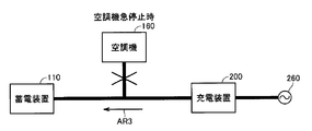
- FIG. 4 is a diagram showing the flow of electric power when the air conditioner 160 suddenly stops during pre-air conditioning.
- the air conditioner 160 may be intermittently operated to maintain a target vehicle interior temperature, and may be stopped when a predetermined target indoor temperature is reached.
- the output power of the charging device 200 cannot be reduced in time, and the power output in the transition period until the charging device 200 stops is supplied to the power storage device 110.
- the power storage device 110 is further charged by this electric power.
- a lithium ion battery may be employed for the power storage device 110.
- this lithium ion battery if overcharging is continued for a long time, oxygen release due to decomposition of the positive electrode or metal lithium deposition on the negative electrode side may occur, which may cause battery failure or deterioration. There is a risk of connection. For this reason, particularly when a lithium ion battery is employed, more strict overcharge prevention is required.
- overcharge prevention control is performed to prevent overcharging of power storage device 110 that occurs in association with intermittent operation of air conditioner 160 in pre-air conditioning during external charging.
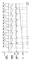
- FIG. 5 is a diagram for explaining the change in the SOC in the comparative example in which the overcharge prevention control is not applied.
- time is shown on the horizontal axis, and the power used by the air conditioner 160, the output power of the charging device 200, the power of the power storage device 110, and the SOC of the power storage device 110 are shown on the vertical axis. 5 and 6 and FIG. 10 described later, for each power, the power in the direction of discharging from power storage device 110 is positive, and the power in the direction of charging power storage device 110 is negative.
- the operation of the air conditioner 160 is started by, for example, a start command from an operator or a start command by a preset timer. Along with this, the output power from the charging device 200 increases. A small amount of power is also discharged from power storage device 110 in order to prevent charging due to sensor error or the like as described above.
- the air conditioner 160 stops when the temperature inside the vehicle reaches the target temperature. Along with this, discharging from the power storage device 110 is also stopped, and output power from the charging device 200 is also stopped. However, since air conditioner 160 operates / stops regardless of the control of charging device 200, charging device 200 starts a decrease in output power after detecting the stop of air conditioner 160. Therefore, even after the air conditioner 160 is stopped, electric power as indicated by D1 in FIG. 5 is continuously output from the charging device 200.
- the transiently output power is not consumed by the air conditioner 160 but becomes charging power for the power storage device 110.
- the electric power of power storage device 110 increases to the charging side (negative side) as between times t2 and t3.
- the SOC of power storage device 110 increases.
- the SOC is gradually increased by intermittently operating the air conditioner 160.
- the SOC of the power storage device 110 may exceed the upper limit value that can be charged, and overcharge may occur.
- FIG. 6 is a diagram for explaining a change in the SOC when the overcharge prevention control of the first embodiment is applied.
- FIG. 6 further shows the high SOC flag HS-FLG on the vertical axis in addition to FIG.
- pre-air conditioning is started at time t11.
- the air conditioner 160 is intermittently operated, the SOC gradually increases from t11 to t15 in the figure.
- air conditioner 160 is stopped at time t16, and the SOC further increases.
- the SOC of power storage device 110 exceeds a threshold value STP_LIM for limiting the driving of charging device 200 (in FIG. 6). Point P1).
- high SOC flag HS-FLG is set on.
- the charging device 200 While the high SOC flag HS-FLG is set to ON, the charging device 200 is not driven even if the operation of the air conditioner 160 is started. Therefore, air conditioner 160 is driven using electric power from power storage device 110. Thereby, the discharge power of power storage device 110 increases and the SOC of power storage device 110 decreases.
- SOC of power storage device 110 becomes lower than threshold value STRT_LIM for canceling the drive restriction of charging device 200 (point P2 in FIG. 6), and accordingly, high SOC flag HS-FLG is set. Set to off.
- the SOC can be maintained near between the threshold values STP_LIM and STRT_LIM. It is possible to prevent overcharging of the power storage device 110.
- threshold value STRT_LIM for releasing the restriction on driving of charging device 200 is set to a value lower than the charging target value. However, even if this charging target value is set as threshold value STRT_LIM. Good. In this way, since the target SOC can be ensured at a minimum, it is possible to prevent the EV travelable distance from being shortened.
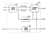
- FIG. 7 is a functional block diagram for explaining the overcharge prevention control executed by the ECU 300 in the first embodiment.
- ECU 300 includes a charge / discharge control unit 310, a charging device control unit 320, and an air conditioner control unit 330.
- Charging / discharging control unit 310 receives detected values of voltage VB and current IB from power storage device 110. Based on these detected values, charging / discharging control unit 310 calculates the SOC of power storage device 110 and charging / discharging power upper limit values Win, Wout. Charging / discharging control unit 310 calculates input / output power PB of power storage device 110 based on detected values of voltage VB and current IB. Further, charge / discharge control unit 310 sets high SOC flag HS-FLG by comparing the calculated SOC with a threshold value.
- charging / discharging control unit 310 outputs input / output power PB, charging / discharging power upper limit values Win, Wout and high SOC flag HS-FLG to charging device control unit 320.
- the air conditioner control unit 330 generates a control signal OPE for controlling the air conditioner 160 based on the input of the pre air conditioner signal and outputs the control signal OPE to the air conditioner 160.
- the air conditioner control unit 330 also outputs a control signal OPE to the charging device control unit 320.
- Charging device control unit 320 receives input / output power PB, charge / discharge power upper limit values Win and Wout and high SOC flag HS-FLG from charge / discharge control unit 310, and control signal OPE from air conditioner control unit 330. Based on these pieces of information, charging device control unit 320 calculates upper limit value Win_chgf and lower limit value Wout_chgf of the output power of charging device 200. Then, charging device control unit 320 sets a command value such that the output power from charging device 200 is between the upper limit value and the lower limit value. Then, charging device control unit 320 generates control signal PWE for driving charging device 200 based on the command value and outputs the control signal PWE to charging device 200.
- FIG. 8 is a flowchart for explaining the details of the overcharge prevention control process executed by ECU 300 in the first embodiment.
- Each step in the flowcharts shown in FIG. 8 and FIGS. 12 and 15 described later is realized by executing a program stored in advance in ECU 300 at a predetermined cycle. Alternatively, some of the steps can be realized by dedicated hardware (electronic circuit).
- FIG. 9 is a diagram showing the state of the high SOC flag HS-FLG corresponding to the change in the SOC of the power storage device 110.
- ECU 300 receives input of pre-air conditioning signal PAC at step (hereinafter abbreviated as S) 400, based on voltage VB and current IB received from power storage device 110. To calculate the SOC.
- threshold value L_LIM is a threshold value for determining whether or not power can be output from power storage device 110 when operating air conditioner 160 in pre-air conditioning.
- the process proceeds to S440, and the ECU 300 determines whether or not the SOC is larger than a threshold value STP_LIM for limiting the driving of the charging apparatus 200.
- ECU 300 further determines whether or not the SOC is smaller than threshold value STRT_LIM for resuming driving of charging apparatus 200.
- state 3 in FIG. 9 since the SOC is equal to or greater than the threshold value STRT_LIM, NO is selected in S445. In this case, the current state of the high SOC flag HS-FLG is maintained. In state 3, since the high SOC flag HS-FLG is off before time t32, the high SOC flag HS-FLG is kept off.
- S450 ECU 300 sets high SOC flag HS-FLG to ON.
- the charging device 200 Since the charging device 200 is stopped, the power of the power storage device 110 is consumed by the air conditioner 160, so that the SOC gradually decreases. Then, at time t34 in FIG. 9, the SOC is equal to or lower than threshold value STP_LIM (NO in S440), but in state 5, the SOC is still equal to or higher than threshold value STRT_LIM (NO in S445), so high SOC flag HS -FLG is kept on and processing proceeds to S460. And the state by which the charging device 200 was stopped is continued (S470).
- the SOC further decreases, and at time t35 in FIG. 9, the SOC becomes smaller than the threshold value STRT_LIM. Then, since the state is similar to state 2, NO is selected in S440, YES is selected in S445, and ECU 300 sets high SOC flag HS-FLG to off. Thereby, NO is set in S460, whereby the operation of charging device 200 is resumed (S475).
- FIG. 10 is a diagram for explaining the change in the SOC when the overcharge prevention control according to the modification of the first embodiment is applied. 10 is obtained by adding the power consumption of the auxiliary load 190 to FIG. 6 described in the first embodiment.
- the time until time t26 is the same as that until time t16 in FIG. 6, and the SOC gradually increases due to intermittent operation of air conditioner 160 in the pre-air conditioning.
- the SOC becomes larger than the threshold value STP_LIM (point P11 in FIG. 10), and the high SOC flag HS-FLG is set to ON.
- the charging device 200 consumes power by the auxiliary load 190 while the operation state is continued.
- the auxiliary machine load 190 for example, a seat heater, a defroster, or the like that consumes more electric power due to heat or the like without operation is suitable.
- FIG. 11 is a functional block diagram for explaining the overcharge prevention control executed by ECU 300 in the modification of the first embodiment.
- an auxiliary machine control unit 340 is added to the functional block diagram of FIG. 7 in the first embodiment.
- the description of the functional blocks overlapping those in FIG. 7 will not be repeated.
- auxiliary machine control unit 340 receives high SOC flag HS-FLG from charge / discharge control unit 310.
- the auxiliary machine control unit 340 outputs the control signal DRV to the auxiliary machine load 190 and the charging device 200 and the power storage device by the auxiliary machine load 190
- the power consumption from 110 is started.
- auxiliary machine control unit 340 outputs control signal DRV to charging device control unit 320.
- Charging device control unit 320 includes input / output power PB from charge / discharge control unit 310, charge / discharge power upper limit values Win and Wout, high SOC flag HS-FLG, control signal OPE from air conditioner control unit 330, and auxiliary equipment.
- the control signal DRV from the control unit 340 is received. Based on these pieces of information, charging device control unit 320 calculates upper limit value Win_chgf and lower limit value Wout_chgf of the output power of charging device 200.
- charging device control unit 320 sets a command value such that the output power from charging device 200 is between the upper limit value and the lower limit value. Then, charging device control unit 320 generates control signal PWE for driving charging device 200 based on the command value and outputs the control signal PWE to charging device 200.
- FIG. 12 is a flowchart for explaining details of the overcharge prevention control process executed by ECU 300 in the modification of the first embodiment.
- step S405 is added to the flowchart of FIG. 8 of the first embodiment, and S470 and S475 are replaced with S480 and S485, respectively.
- S470 and S475 are replaced with S480 and S485, respectively.
- FIG. 12 the description of the same steps as those in FIG. 8 will not be repeated.
- ECU 300 receives pre-air conditioning signal PAC and calculates the SOC of power storage device 110 in S400, and operates charging device 200 in S405.
- ECU 300 determines in S410 whether the calculated SOC is smaller than threshold value L_LIM.
- ECU 300 stops the air conditioner (S420) and stops power consumption by auxiliary load 190 (S485). As a result, power storage device 110 is charged until the SOC reaches the level at which pre-air conditioning is possible.
- ECU 300 operates the air conditioner (S430) and sets high SOC flag HS-FLG by the processing of S440 to S455 as in FIG. Set.
- ECU 300 determines in S460 whether or not high SOC flag HS-FLG is set to ON.
- the power charged to power storage device 110 by intermittent operation of air conditioner 160 can be consumed by auxiliary load 190 in pre-air conditioning during external charging. 110 can be prevented from being overcharged.
- the discharge power upper limit value of power storage device 110 is set. A description will be given of a configuration that performs control so as to compensate for insufficient power by operating charging device 200 when Wout is exceeded.
- FIGS. 13 and 14 are diagrams for explaining the upper and lower limit values of the output power of charging device 200 when power storage device 110 is charged and discharged.
- FIG. 13 shows a case where the power storage device 110 is discharged
- FIG. 14 shows a case where the power storage device 110 is charged. 13 and 14, the case where the charge / discharge power of power storage device 110 is the charge / discharge power upper limit value will be described.
- Pbd be the driving power required to drive air conditioner 160 at a certain point in time.
- drive power Pbd is supplied from power storage device 110 and charging device 200.
- the power output from the charging device 200 at this time Is Wout_chgf, it can be expressed as in equation (1).
- Wout_chgf Pbd ⁇ Wout (2)
- the output power Wout_chgf of the charging device 200 is negative or zero, it means that power can be supplied to the air conditioner 160 only with the discharge power from the power storage device 110. Therefore, in this case, the charging device 200 can be stopped.
- Wout_chgf described above is a lower limit value of the output power of charging device 200, and charging device 200 outputs at least power corresponding to this lower limit value Wout_chgf for protection of power storage device 110 and operation of air conditioner 160. It is necessary to do.
- FIG. 14 shows a case where the power storage device 110 is charged, so that both the power charged to the power storage device 110 and the power for driving the air conditioner 160 are supplied from the charging device 200.
- Win_chgf Win + Pbd (3)
- power exceeding Win_chgf output from the charging device 200
- power exceeding the charging power upper limit value Win is supplied to the power storage device 110.
- Win_chgf is the upper limit value of the output power of the charging device 200, and the charging device 200 needs to be controlled so that the output power does not exceed the output upper limit value Win_chgf.
- FIG. 15 is a flowchart for explaining the details of the overcharge prevention control process in consideration of the discharge power upper limit value of power storage device 110, which is executed by ECU 300 in the second embodiment.
- steps S405 and S465 are added to the flowchart of FIG. 8 of the first embodiment.
- the description of the same steps as those in FIG. 8 will not be repeated.
- ECU 300 next determines discharge power upper limit value Wout of power storage device 110 and control command OPE to air conditioner 160 in S405.
- the output lower limit value Wout_chgf of the charging device 200 is calculated from the driving power of the air conditioner 160 obtained based on the above.
- Embodiment 3 In Embodiment 1, the case of having one power storage device as the power supply system has been described. However, the number of power storage devices is not limited to this, and the present invention is also applied to the case of having a plurality of power storage devices. Is possible.
- FIG. 16 is an overall block diagram of a vehicle 100A equipped with a power supply system having a plurality of power storage devices according to the third embodiment.
- the description of the same elements as those in FIG. 1 of the first embodiment will not be repeated.
- vehicle 100 ⁇ / b> A further includes power storage devices 111 and 112 in addition to power storage device 110. Further, relays 116 and 117 respectively corresponding to power storage devices 111 and 112 are further included. Relays 116 and 117 have the same function as SMR 115 in power storage device 110.
- vehicle 100A includes PCU 120A instead of PCU 120.
- PCU 120A further includes a converter 123 and a capacitor C3 in addition to converter 121, inverter 122, and capacitors C1 and C2.
- Converter 123 is connected in parallel to converter 121 with respect to inverter 122.
- power storage devices 111 and 112 are connected in parallel to converter 123 via power lines PL3 and NL3.
- Converter 121 performs power conversion between power lines PL1, NL1 and power lines HPL, NL1 based on control signal PWC1 from ECU 300.
- Converter 123 performs power conversion between power lines PL3, NL3 and power lines HPL, NL1 based on control signal PWC2 from ECU 300.
- the capacitor C3 is provided between the power lines PL3 and NL3, and reduces voltage fluctuation between the power lines PL3 and NL3.
- Charging device 200 is connected to power lines PL3 and NL3 via relay 210. With such a configuration, the power storage devices 110, 111, and 112 can be charged with power from the charging device 200.
- output power from charging device 200 is boosted by converter 123, further stepped down by converter 121, and supplied to power storage device 110.
- the output power from the charging device 200 is supplied to the air conditioner 160 via the converter 123 and the converter 121 as in the case of charging the power storage device 110.
- relays 116 and 117 of power storage devices 111 and 112 are opened, and SMR 115 is closed. Thereby, air conditioner 160 is driven using the electric power from charging device 200 and power storage device 110 as in the first embodiment.
- the configuration of the first embodiment, the modified example thereof, and the second embodiment can be applied to a power supply system having a plurality of power storage devices as in the vehicle 100A.
- overcharging of power storage device 110 can be prevented during pre-air conditioning during external charging.
- threshold value STP_LIM and the threshold value STRT_LIM in the present embodiment are examples of the “first reference value” and the “second reference value” of the present invention, respectively.
Abstract
Description
好ましくは、制御装置は、蓄電装置の充電状態を検出するとともに、蓄電装置の充電状態が第1の基準値より大きい場合は、蓄電装置に蓄えられた電力を補機負荷によって消費させる。
本発明による車両用の電源システムの制御方法であって、車両は、充電が可能な蓄電装置と、充電装置と、空調機と、蓄電装置からの電力を受ける補機負荷とを含む。充電装置は、外部電源から供給される交流電力を用いて蓄電装置を充電する外部充電を行なう。空調機は、充電装置および蓄電装置から電源が供給され、車両の室内を空調する。そして、制御方法は、外部充電中に空調機を運転するステップと、空調機が間欠運転される場合に、蓄電装置が過充電になるおそれがあるときには、蓄電装置から出力される電力が増加されるように、充電装置および補機負荷の少なくとも一方を制御するステップとを備える。
図1は、本発明の実施の形態に従う電源システムを搭載した車両100の全体ブロック図である。
図2を参照して、PCU120は、コンバータ121と、インバータ122と、コンデンサC1,C2とを含む。
図3は、外部充電時に空調機160が運転されている場合の電力の流れを示した図である。
そこで本実施の形態においては、外部充電時のプレ空調において、空調機160の間欠運転に伴って発生する蓄電装置110の過充電を防止するための過充電防止制御を行なう。
図8および図9を参照して、ECU300は、ステップ(以下、ステップをSと略す。)400にて、プレ空調信号PACの入力を受けると、蓄電装置110から受ける電圧VBおよび電流IBに基づいてSOCを演算する。
S445では、ECU300は、さらにSOCが充電装置200の駆動を再開するためのしきい値STRT_LIMより小さいか否かを判定する。
上述の実施の形態1においては、高SOCフラグHS-FLGがオンとなっている間は、充電装置200を停止させることによって、蓄電装置110の過充電を防止する構成について説明した。
また、補機制御部340は、制御信号DRVを充電装置制御部320へ出力する。
充電装置制御部320は、充放電制御部310からの入出力電力PB、充放電電力上限値Win,Woutおよび高SOCフラグHS-FLGと、空調機制御部330からの制御信号OPEと、補機制御部340からの制御信号DRVとを受ける。充電装置制御部320は、これらの情報に基づいて、充電装置200の出力電力の上限値Win_chgfおよび下限値Wout_chgfを演算する。そして、充電装置制御部320は、充電装置200からの出力電力が、この上限値と下限値との間となるような指令値を設定する。そして、充電装置制御部320は、その指令値に基づいて充電装置200を駆動するための制御信号PWEを生成して充電装置200に出力する。
実施の形態1においては、高SOCフラグHS-FLGがオンに設定されている間は、充電装置200を停止する構成について説明した。
これより、充電装置200の出力電力は、式(1)を変形して式(2)のように表わされる。
ここで、充電装置200の出力電力Wout_chgfが負またはゼロとなる場合は、蓄電装置110からの放電電力のみで、空調機160へ電力の供給が可能であることを意味する。したがって、この場合は、充電装置200を停止することができる。
式(3)からわかるように、充電装置200からWin_chgfを超えるような電力が出力された場合には、蓄電装置110には充電電力上限値Winを超える電力が供給されることになる。
実施の形態1においては、電源システムとして1つの蓄電装置を有する場合について説明したが、蓄電装置の個数についてはこれに限定されるものではなく、複数の蓄電装置を有する場合においても本発明は適用可能である。
このような構成とすることで、充電装置200からの電力によって蓄電装置110,111,112を充電することができる。なお、蓄電装置110を充電する場合には、充電装置200からの出力電力は、コンバータ123で昇圧され、さらにコンバータ121で降圧されて蓄電装置110へ供給される。
Claims (14)
- [規則91に基づく訂正 24.03.2010]
車両用の電源システムであって、
充電が可能な蓄電装置(110,111,112)と、
外部電源(260)から供給される交流電力を用いて前記蓄電装置(110)を充電する外部充電を行なうように構成された充電装置(200)と、
前記充電装置(200)および前記蓄電装置(110)から電力が供給され、前記車両の室内を空調するための空調機(160)と、
前記蓄電装置(110)からの電力を受ける補機負荷(190)と、
前記外部充電中に前記空調機(160)が間欠運転される場合に、前記蓄電装置(110)が過充電になるおそれがあるときには、前記蓄電装置(110)から出力される電力が増加されるように、前記充電装置(200)および前記補機負荷(190)の少なくとも一方を制御するための制御装置(300)とを備える、車両用の電源システム。 - 前記制御装置(300)は、前記蓄電装置(110)の充電状態を検出するとともに、前記蓄電装置(110)の充電状態が第1の基準値より大きい場合は、前記充電装置(200)から出力される電力を停止する、請求の範囲第1項に記載の車両用の電源システム。
- 前記制御装置(300)は、前記蓄電装置(110)の充電状態に基づいて前記蓄電装置(110)の放電電力上限値を設定するとともに、前記蓄電装置(110)から出力される電力が前記放電電力上限値を超過する場合には、前記蓄電装置(110)の充電状態が前記第1の基準値より大きい場合であっても、前記放電電力上限値を超過する分の電力を前記充電装置(200)によって出力させる、請求の範囲第2項に記載の車両用の電源システム。
- 前記制御装置(300)は、前記蓄電装置(110)の充電状態が前記第1の基準値よりも小さい第2の基準値より小さくなった場合は、前記充電装置(200)から出力される電力を増加する、請求の範囲第2項または第3項に記載の車両用の電源システム。
- 前記第2の基準値は、前記蓄電装置(110)の外部充電完了時の充電目標値である、請求の範囲第4項に記載の車両用の電源システム。
- 前記制御装置(300)は、前記蓄電装置(110)の充電状態を検出するとともに、前記蓄電装置(110)の充電状態が第1の基準値より大きい場合は、前記蓄電装置(110)に蓄えられた電力を前記補機負荷(190)によって消費させる、請求の範囲第1項に記載の車両用の電源システム。
- 前記制御装置(300)は、前記蓄電装置(110)の充電状態が前記第1の基準値よりも小さい第2の基準値より小さくなった場合は、前記補機負荷(190)による前記蓄電装置(110)に蓄えられた電力の消費を停止する、請求の範囲第6項に記載の車両用の電源システム。
- 前記蓄電装置は、複数の蓄電装置(110,111,112)を含む、請求の範囲第1項に記載の車両用の電源システム。
- [規則91に基づく訂正 24.03.2010]
車両用の電源システムの制御方法であって、
前記車両は、
充電が可能な蓄電装置(110,111,112)と、
外部電源(260)から供給される交流電力を用いて前記蓄電装置(110)を充電する外部充電を行なうように構成された充電装置(200)と、
前記充電装置(200)および前記蓄電装置(110)から電力が供給され、前記車両の室内を空調するための空調機(160)と、
前記蓄電装置(110)からの電力を受ける補機負荷(190)とを含み、
前記制御方法は、
前記外部充電中に前記空調機(160)を運転するステップと、
前記空調機(160)が間欠運転される場合に、前記蓄電装置(110)が過充電になるおそれがあるときには、前記蓄電装置(110)から出力される電力が増加されるように、前記充電装置(200)および前記補機負荷(190)の少なくとも一方を制御するステップとを備える、車両用の電源システムの制御方法。 - 前記蓄電装置(110)の充電状態を検出するステップと、
前記蓄電装置(110)の充電状態が第1の基準値より大きい場合は、前記充電装置(200)から出力される電力が停止させるステップとをさらに備える、請求の範囲第9項に記載の車両用の電源システムの制御方法。 - 前記蓄電装置(110)の充電状態に基づいて前記蓄電装置(110)の放電電力上限値を設定するステップと、
前記蓄電装置(110)から出力される電力が前記放電電力上限値を超過する場合には、前記蓄電装置(110)の充電状態が前記第1の基準値より大きい場合であっても、前記放電電力上限値を超過する電力を前記充電装置(200)によって出力させるステップとをさらに備える、請求の範囲第10項に記載の車両用の電源システムの制御方法。 - 前記蓄電装置(110)の充電状態が前記第1の基準値よりも小さい第2の基準値より小さくなった場合は、前記充電装置(200)から出力される電力を増加するステップをさらに備える、請求の範囲第10項または第11項に記載の車両用の電源システムの制御方法。
- 前記蓄電装置(110)の充電状態を検出するステップと、
前記蓄電装置(110)の充電状態が第1の基準値より大きい場合は、前記蓄電装置(110)に蓄えられた電力を前記補機負荷(190)によって消費させるステップとをさらに備える、請求の範囲第9項に記載の車両用の電源システムの制御方法。 - 前記蓄電装置(110)の充電状態が前記第1の基準値よりも小さい第2の基準値より小さくなった場合は、前記補機負荷(190)による前記蓄電装置(110)に蓄えられた電力の消費を停止するステップをさらに備える、請求の範囲第13項に記載の車両用の電源システムの制御方法。
Priority Applications (5)
| Application Number | Priority Date | Filing Date | Title |
|---|---|---|---|
| US13/259,328 US8639413B2 (en) | 2009-09-09 | 2009-09-09 | Vehicle power supply system and method for controlling the same |
| JP2011530658A JP5206879B2 (ja) | 2009-09-09 | 2009-09-09 | 車両用の電源システムおよびその制御方法 |
| CN200980161360.7A CN102574471B (zh) | 2009-09-09 | 2009-09-09 | 车辆用的电源系统及其控制方法 |
| EP09849181.4A EP2476574B1 (en) | 2009-09-09 | 2009-09-09 | Power supply system for vehicle and method of controlling same |
| PCT/JP2009/065702 WO2011030401A1 (ja) | 2009-09-09 | 2009-09-09 | 車両用の電源システムおよびその制御方法 |
Applications Claiming Priority (1)
| Application Number | Priority Date | Filing Date | Title |
|---|---|---|---|
| PCT/JP2009/065702 WO2011030401A1 (ja) | 2009-09-09 | 2009-09-09 | 車両用の電源システムおよびその制御方法 |
Publications (1)
| Publication Number | Publication Date |
|---|---|
| WO2011030401A1 true WO2011030401A1 (ja) | 2011-03-17 |
Family
ID=43732089
Family Applications (1)
| Application Number | Title | Priority Date | Filing Date |
|---|---|---|---|
| PCT/JP2009/065702 WO2011030401A1 (ja) | 2009-09-09 | 2009-09-09 | 車両用の電源システムおよびその制御方法 |
Country Status (5)
| Country | Link |
|---|---|
| US (1) | US8639413B2 (ja) |
| EP (1) | EP2476574B1 (ja) |
| JP (1) | JP5206879B2 (ja) |
| CN (1) | CN102574471B (ja) |
| WO (1) | WO2011030401A1 (ja) |
Cited By (5)
| Publication number | Priority date | Publication date | Assignee | Title |
|---|---|---|---|---|
| KR20120124815A (ko) * | 2011-05-04 | 2012-11-14 | 엘지전자 주식회사 | 전기 자동차 및 이의 구동 방법 |
| CN103010028A (zh) * | 2011-09-27 | 2013-04-03 | 三菱自动车工业株式会社 | 电力切换设备 |
| US20130162023A1 (en) * | 2011-07-29 | 2013-06-27 | Sanyo Electric Co., Ltd. | Switching device, and solar power generation system and vehicle driving system using the same |
| WO2013121899A1 (ja) * | 2012-02-13 | 2013-08-22 | シャープ株式会社 | 電気機器 |
| CN103534918A (zh) * | 2011-05-13 | 2014-01-22 | 丰田自动车株式会社 | 车辆的电源系统 |
Families Citing this family (25)
| Publication number | Priority date | Publication date | Assignee | Title |
|---|---|---|---|---|
| KR101144033B1 (ko) * | 2009-12-04 | 2012-05-23 | 현대자동차주식회사 | 하이브리드 차량의 모터 구동 시스템 제어 방법 |
| JP2012183958A (ja) * | 2011-03-07 | 2012-09-27 | Hokuriku Electric Power Co Inc:The | 電気自動車の暖房方法及び装置 |
| US9533591B2 (en) * | 2012-01-30 | 2017-01-03 | Toyota Jidosha Kabushiki Kaisha | Vehicular power reception device, power supply apparatus, and electric power transfer system |
| US9174633B2 (en) * | 2012-05-04 | 2015-11-03 | Ford Global Technologies, Llc | Methods and systems providing driveline braking |
| US8894541B2 (en) | 2012-05-04 | 2014-11-25 | Ford Global Technologies, Llc | Methods and systems for a vehicle driveline control during varying driving conditions |
| US8998771B2 (en) | 2012-05-04 | 2015-04-07 | Ford Global Technologies, Llc | Methods and systems for a vehicle driveline |
| US9260107B2 (en) | 2012-05-04 | 2016-02-16 | Ford Global Technologies, Llc | Methods and systems for operating a driveline disconnect clutch responsive to engine operating conditions |
| US9393954B2 (en) | 2012-05-04 | 2016-07-19 | Ford Global Technologies, Llc | Methods and systems for engine stopping |
| US9068546B2 (en) | 2012-05-04 | 2015-06-30 | Ford Global Technologies, Llc | Methods and systems for engine cranking |
| CN103419650B (zh) * | 2012-05-22 | 2016-03-30 | 比亚迪股份有限公司 | 电动汽车、电动汽车的动力系统及电池加热方法 |
| WO2014045776A1 (ja) * | 2012-09-19 | 2014-03-27 | 日産自動車株式会社 | 車両制御システム、車両情報提供装置、及び、車両情報提供方法 |
| JP5729401B2 (ja) * | 2013-02-01 | 2015-06-03 | トヨタ自動車株式会社 | 電動車両 |
| US9588184B2 (en) | 2013-04-30 | 2017-03-07 | Nuvera Fuel Cells, Inc. | Battery state-of-charge aggregation method |
| JP5642253B1 (ja) * | 2013-11-08 | 2014-12-17 | 三菱電機株式会社 | 車両用エネルギーマネジメント装置 |
| CN104175837A (zh) * | 2014-09-12 | 2014-12-03 | 国家电网公司 | 一种汽车停车后外接电源或行驶的驱动冷暖空调装置 |
| US9630518B2 (en) | 2015-06-09 | 2017-04-25 | Ford Global Technologies, Llc | Dynamic grid loading using plug-in electrified vehicles |
| JP2019062711A (ja) * | 2017-09-28 | 2019-04-18 | 株式会社デンソー | 車載用補機装置 |
| JP6613528B2 (ja) * | 2017-11-02 | 2019-12-04 | 本田技研工業株式会社 | 電動車両 |
| US11050272B2 (en) * | 2017-12-04 | 2021-06-29 | Nio Usa, Inc. | Open line detection during pre-charge |
| JP6584019B2 (ja) * | 2017-12-21 | 2019-10-02 | 本田技研工業株式会社 | 電動車両 |
| JP7003684B2 (ja) * | 2018-01-23 | 2022-01-20 | 株式会社オートネットワーク技術研究所 | 車両用シートの給電装置 |
| US10392018B1 (en) * | 2018-09-27 | 2019-08-27 | Ford Global Technologies, Llc | Vehicle and regenerative braking control system for a vehicle |
| JP2020108217A (ja) | 2018-12-26 | 2020-07-09 | トヨタ自動車株式会社 | 電気自動車 |
| JP7253952B2 (ja) * | 2019-03-27 | 2023-04-07 | 株式会社Subaru | 車両 |
| JP6946376B2 (ja) | 2019-06-24 | 2021-10-06 | 本田技研工業株式会社 | 空調装置、空調制御方法、およびプログラム |
Citations (6)
| Publication number | Priority date | Publication date | Assignee | Title |
|---|---|---|---|---|
| JPH07193901A (ja) * | 1993-12-28 | 1995-07-28 | Nissan Motor Co Ltd | 電気自動車用空調装置 |
| JPH0865816A (ja) * | 1994-08-25 | 1996-03-08 | Honda Motor Co Ltd | 電気自動車用充電制御装置 |
| JP2007245999A (ja) * | 2006-03-17 | 2007-09-27 | Toyota Motor Corp | 車両の制御装置および車両 |
| WO2009034872A1 (ja) | 2007-09-10 | 2009-03-19 | Toyota Jidosha Kabushiki Kaisha | 蓄電装置の充電制御装置および充電制御方法 |
| WO2009104305A1 (ja) | 2008-02-19 | 2009-08-27 | トヨタ自動車株式会社 | 車両および二次電池の充電状態推定方法 |
| JP2009201170A (ja) * | 2008-02-19 | 2009-09-03 | Toyota Motor Corp | 充電制御システム |
Family Cites Families (19)
| Publication number | Priority date | Publication date | Assignee | Title |
|---|---|---|---|---|
| JP2914057B2 (ja) | 1992-11-16 | 1999-06-28 | 日産自動車株式会社 | ハイブリッド自動車 |
| JPH07212902A (ja) | 1993-12-02 | 1995-08-11 | Nippondenso Co Ltd | 電気自動車の空調装置制御システム |
| JPH0865814A (ja) | 1994-08-25 | 1996-03-08 | Honda Motor Co Ltd | 電気自動車用充電制御装置 |
| JPH08268036A (ja) | 1995-03-28 | 1996-10-15 | Calsonic Corp | 電気自動車用冷暖房装置 |
| JPH0976740A (ja) | 1995-09-08 | 1997-03-25 | Aqueous Res:Kk | ハイブリッド車両 |
| JP2000078701A (ja) | 1998-08-27 | 2000-03-14 | Toyota Motor Corp | 電気自動車用空調装置 |
| JP2001063347A (ja) | 1999-08-26 | 2001-03-13 | Denso Corp | 車両用空調制御システム |
| US6242873B1 (en) * | 2000-01-31 | 2001-06-05 | Azure Dynamics Inc. | Method and apparatus for adaptive hybrid vehicle control |
| US6586940B2 (en) * | 2000-03-13 | 2003-07-01 | Nippon Telegraph And Telephone Corporation | Capacity estimation method, degradation estimation method and degradation estimation apparatus for lithium-ion cells, and lithium-ion batteries |
| JP3711445B2 (ja) | 2001-02-21 | 2005-11-02 | 株式会社デンソー | 車両用空調充電制御装置および車載電池の充電管理装置 |
| JP3809824B2 (ja) | 2002-09-10 | 2006-08-16 | トヨタ自動車株式会社 | ハイブリッド車 |
| JP3933030B2 (ja) | 2002-10-22 | 2007-06-20 | 株式会社デンソー | ハイブリッド車用空調装置 |
| JP2004166367A (ja) | 2002-11-12 | 2004-06-10 | Nissan Motor Co Ltd | ハイブリッド車両の電池制御装置 |
| US7224132B2 (en) * | 2004-01-22 | 2007-05-29 | Wavecrest Laboratories, Llc. | Portable range extender operable in automatic and manual modes |
| US7259664B1 (en) * | 2004-06-16 | 2007-08-21 | Chahee Peter Cho | Sensorless fuel level and oil change indicators |
| JP4049138B2 (ja) | 2004-08-23 | 2008-02-20 | トヨタ自動車株式会社 | 車両の制御装置 |
| US7715957B2 (en) | 2006-02-22 | 2010-05-11 | Toyota Jidosha Kabushiki Kaisha | Control device of vehicle |
| JP4715708B2 (ja) * | 2006-10-03 | 2011-07-06 | トヨタ自動車株式会社 | 電動車両および車両充電システム |
| US7426910B2 (en) | 2006-10-30 | 2008-09-23 | Ford Global Technologies, Llc | Engine system having improved efficiency |
-
2009
- 2009-09-09 US US13/259,328 patent/US8639413B2/en active Active
- 2009-09-09 CN CN200980161360.7A patent/CN102574471B/zh not_active Expired - Fee Related
- 2009-09-09 JP JP2011530658A patent/JP5206879B2/ja active Active
- 2009-09-09 WO PCT/JP2009/065702 patent/WO2011030401A1/ja active Application Filing
- 2009-09-09 EP EP09849181.4A patent/EP2476574B1/en not_active Not-in-force
Patent Citations (6)
| Publication number | Priority date | Publication date | Assignee | Title |
|---|---|---|---|---|
| JPH07193901A (ja) * | 1993-12-28 | 1995-07-28 | Nissan Motor Co Ltd | 電気自動車用空調装置 |
| JPH0865816A (ja) * | 1994-08-25 | 1996-03-08 | Honda Motor Co Ltd | 電気自動車用充電制御装置 |
| JP2007245999A (ja) * | 2006-03-17 | 2007-09-27 | Toyota Motor Corp | 車両の制御装置および車両 |
| WO2009034872A1 (ja) | 2007-09-10 | 2009-03-19 | Toyota Jidosha Kabushiki Kaisha | 蓄電装置の充電制御装置および充電制御方法 |
| WO2009104305A1 (ja) | 2008-02-19 | 2009-08-27 | トヨタ自動車株式会社 | 車両および二次電池の充電状態推定方法 |
| JP2009201170A (ja) * | 2008-02-19 | 2009-09-03 | Toyota Motor Corp | 充電制御システム |
Non-Patent Citations (1)
| Title |
|---|
| See also references of EP2476574A4 * |
Cited By (11)
| Publication number | Priority date | Publication date | Assignee | Title |
|---|---|---|---|---|
| KR20120124815A (ko) * | 2011-05-04 | 2012-11-14 | 엘지전자 주식회사 | 전기 자동차 및 이의 구동 방법 |
| KR101631085B1 (ko) * | 2011-05-04 | 2016-06-16 | 엘지전자 주식회사 | 전기 자동차 및 이의 구동 방법 |
| CN103534918A (zh) * | 2011-05-13 | 2014-01-22 | 丰田自动车株式会社 | 车辆的电源系统 |
| US20130162023A1 (en) * | 2011-07-29 | 2013-06-27 | Sanyo Electric Co., Ltd. | Switching device, and solar power generation system and vehicle driving system using the same |
| CN103503288A (zh) * | 2011-07-29 | 2014-01-08 | 三洋电机株式会社 | 开关装置、使用开关装置的太阳光发电系统及车辆驱动系统 |
| US9479158B2 (en) * | 2011-07-29 | 2016-10-25 | Panasonic Intellectual Property Management Co., Ltd. | Switching device, and solar power generation system and vehicle driving system using the same |
| CN103010028A (zh) * | 2011-09-27 | 2013-04-03 | 三菱自动车工业株式会社 | 电力切换设备 |
| JP2013074658A (ja) * | 2011-09-27 | 2013-04-22 | Mitsubishi Motors Corp | 電力切替装置 |
| CN103010028B (zh) * | 2011-09-27 | 2015-07-15 | 三菱自动车工业株式会社 | 电力切换设备 |
| US9162576B2 (en) | 2011-09-27 | 2015-10-20 | Mitsubishi Jidosha Kogyo Kabushiki Kaisha | Power switching apparatus |
| WO2013121899A1 (ja) * | 2012-02-13 | 2013-08-22 | シャープ株式会社 | 電気機器 |
Also Published As
| Publication number | Publication date |
|---|---|
| US20120022744A1 (en) | 2012-01-26 |
| CN102574471A (zh) | 2012-07-11 |
| JP5206879B2 (ja) | 2013-06-12 |
| US8639413B2 (en) | 2014-01-28 |
| EP2476574A1 (en) | 2012-07-18 |
| JPWO2011030401A1 (ja) | 2013-02-04 |
| EP2476574A4 (en) | 2013-08-07 |
| EP2476574B1 (en) | 2014-10-22 |
| CN102574471B (zh) | 2014-03-12 |
Similar Documents
| Publication | Publication Date | Title |
|---|---|---|
| JP5206879B2 (ja) | 車両用の電源システムおよびその制御方法 | |
| CN103221246B (zh) | 车辆的充电装置 | |
| JP5740269B2 (ja) | 車両用制御装置 | |
| EP2669131B1 (en) | Hybrid vehicle | |
| JP5515897B2 (ja) | 車両の制御装置およびそれを搭載する車両 | |
| KR102302783B1 (ko) | 차량 구동 시스템 및 방법 | |
| JP2012085481A (ja) | 電動車両 | |
| CN102844956A (zh) | 蓄电装置的控制装置以及搭载该蓄电装置的控制装置的车辆 | |
| JP2011087408A (ja) | 車両の電源システム | |
| JP2012244875A (ja) | 車両の電源システムおよびそれを備える車両 | |
| JP2011072067A (ja) | 車両の電源システムおよびそれを備える電動車両 | |
| JP2009247057A (ja) | 電気自動車の制御装置 | |
| JP2013090486A (ja) | 電気自動車用電力供給装置 | |
| JP2012080689A (ja) | 電気自動車用電源装置 | |
| JP2015057009A (ja) | 車両 | |
| CN111976704A (zh) | 一种增程式电动汽车的控制方法、装置与系统 | |
| JP5510259B2 (ja) | 車両用電力制御装置 | |
| JP2010119176A (ja) | 車載用電源装置 | |
| JP2019187061A (ja) | 電力制御システム | |
| JP2015035919A (ja) | 車両および車両の制御方法 | |
| JP5885236B2 (ja) | 車両の電源装置 | |
| JP5625715B2 (ja) | 車両の制御装置および制御方法 | |
| JP2008302852A (ja) | ハイブリッド自動車の制御装置 | |
| JP2015104222A (ja) | 蓄電システム | |
| JP2016157647A (ja) | 蓄電システム |
Legal Events
| Date | Code | Title | Description |
|---|---|---|---|
| WWE | Wipo information: entry into national phase |
Ref document number: 200980161360.7 Country of ref document: CN |
|
| 121 | Ep: the epo has been informed by wipo that ep was designated in this application |
Ref document number: 09849181 Country of ref document: EP Kind code of ref document: A1 |
|
| WWE | Wipo information: entry into national phase |
Ref document number: 13259328 Country of ref document: US |
|
| WWE | Wipo information: entry into national phase |
Ref document number: 2011530658 Country of ref document: JP |
|
| NENP | Non-entry into the national phase |
Ref country code: DE |
|
| WWE | Wipo information: entry into national phase |
Ref document number: 2009849181 Country of ref document: EP |