WO2011024863A1 - 情報端末、接続切り替え方法、および接続切り替えプログラム - Google Patents
情報端末、接続切り替え方法、および接続切り替えプログラム Download PDFInfo
- Publication number
- WO2011024863A1 WO2011024863A1 PCT/JP2010/064399 JP2010064399W WO2011024863A1 WO 2011024863 A1 WO2011024863 A1 WO 2011024863A1 JP 2010064399 W JP2010064399 W JP 2010064399W WO 2011024863 A1 WO2011024863 A1 WO 2011024863A1
- Authority
- WO
- WIPO (PCT)
- Prior art keywords
- unit
- area
- receiving
- content
- receiving unit
- Prior art date
- Legal status (The legal status is an assumption and is not a legal conclusion. Google has not performed a legal analysis and makes no representation as to the accuracy of the status listed.)
- Ceased
Links
Images



Classifications
-
- H—ELECTRICITY
- H04—ELECTRIC COMMUNICATION TECHNIQUE
- H04W—WIRELESS COMMUNICATION NETWORKS
- H04W48/00—Access restriction; Network selection; Access point selection
- H04W48/18—Selecting a network or a communication service
-
- H—ELECTRICITY
- H04—ELECTRIC COMMUNICATION TECHNIQUE
- H04W—WIRELESS COMMUNICATION NETWORKS
- H04W4/00—Services specially adapted for wireless communication networks; Facilities therefor
- H04W4/02—Services making use of location information
- H04W4/024—Guidance services
-
- H—ELECTRICITY
- H04—ELECTRIC COMMUNICATION TECHNIQUE
- H04W—WIRELESS COMMUNICATION NETWORKS
- H04W4/00—Services specially adapted for wireless communication networks; Facilities therefor
- H04W4/02—Services making use of location information
Definitions
- the present invention relates to an information terminal, a connection switching method, and a connection switching program.
- portable TV broadcast receivers that can receive digital TV broadcasts and analog TV broadcasts, and multifunctional car navigation devices that can watch these broadcasts are known.
- the reception status of radio waves may deteriorate and screen display and audio output may be disturbed, or content may not be viewed.
- Patent Document 1 is a mobile receiver that measures the received electric field strength in real time, if the received electric field strength sharply decreases, content matching that occurs during connection switching processing is performed. There is a possibility that the delay processing for maintaining the performance is not in time, the screen is not displayed, or the audio output is stopped. Further, depending on the reception status, the connection destination may be frequently switched. Further, if the connection destination is frequently changed, the delay processing described above increases, and the battery consumption of the apparatus becomes severe.
- the reception quality level is set to analog TV broadcasting. In some cases, it may be lower than when receiving.
- the present invention selects a connection destination in consideration of the reception status of radio waves in advance, and switches to an appropriate connection destination according to the reception status, a connection switching method, and a connection switching program.
- the purpose is to provide.
- An information terminal is transmitted by a first receiving unit that receives a signal representing content transmitted by a first communication network, and a second communication network that is different from the first communication network.
- a second receiving unit for receiving a signal representing the content to be transmitted, an input unit for inputting destination information or waypoint information to the destination, a current position specifying unit for specifying the current position, and a destination from the current position
- a navigation unit that searches for a route to a place or a waypoint, and guides based on the found route, and a route from the current position to a destination or a waypoint.
- Area information indicating whether or not at least one of the signals representing the content can be received is acquired, and the content is acquired by at least one of the first receiving unit and the second receiving unit based on the acquired area information.
- a receivable area determining unit that determines whether or not a signal can be received, and a first receiving unit or a second receiving unit that receives a signal representing content based on the determination by the receivable area determining unit.
- a communication control unit that determines any of the receiving units.
- the information terminal which is one aspect of the present invention preferably includes a storage unit in which area information is stored in addition to the configuration of the information terminal described above.
- a signal representing content is preferentially received by either the first reception unit or the second reception unit. It is possible to input selection instruction information for instructing the communication control unit to set the connection to be performed, and the communication control unit represents the content in both the first reception unit and the second reception unit by the receivable area determination unit. A section determined to be an area in which a signal can be received is selected with priority given to either the first receiving unit or the second receiving unit based on the selection instruction information input from the input unit. Is preferred.
- the communication control unit is configured to communicate with the first reception unit in the route from the current position to the destination or the waypoint. It is preferable to select the second receiving unit so that the number of times of switching is minimized.
- the communication control unit is based on the connectable area information specified by the determination of the receivable area determination unit, It is preferable to determine the timing for switching from one of the first receiving unit and the second receiving unit to the other.
- the communication control unit determines the timing described above based on the connectable area information specified by the determination of the receivable area determination unit and the predetermined connection switching pattern. Is preferred.
- the current position of the information terminal can receive a signal representing content at either the first receiving unit or the second receiving unit.
- the first receiving unit or the second receiving unit determined to be able to receive the signal representing the content in the second area while staying in the first area by the communication control unit What is chosen is preferred.
- reception of a signal indicating the content of the current position of the information terminal only at either the first reception unit or the second reception unit When moving from the second area determined to be possible to the first area determined to be capable of receiving the signal representing the content in both the first receiving unit and the second receiving unit
- the communication control unit selects either the first reception unit or the second reception unit after moving to the first area.
- reception of a signal indicating the content of the current position of the information terminal only at either the first reception unit or the second reception unit It is possible to receive a signal representing content only from a second receiving unit that is determined to be capable of receiving a signal representing content in the second area from a second area determined to be capable of receiving the signal.
- a second receiving unit that is determined to be capable of receiving a signal representing content in the second area
- the signal representing the content in the third area can be received immediately before moving from the second area to the third area. What selects either a 1st receiving part or a 2nd receiving part by a communication control part is preferable.
- the current position of the information terminal is not received by the first receiving unit and the second receiving unit in a signal representing content.
- the fifth area determined to be capable of receiving the signal representing the content in at least one of the first receiving unit and the second receiving unit
- the first receiving unit or the second receiving unit determined to be able to receive the signal representing the content in the fifth area. What is selected by the communication control unit is preferable.
- the current position of the information terminal receives a signal representing content in at least one of the first receiving unit and the second receiving unit.
- the signal representing the content is received by either the first receiving unit or the second receiving unit connected in the fifth area until the signal representing the content cannot be actually received. preferable.
- the communication control unit restricts the number of times to a number smaller than a predetermined number set as the number of scan processes for receiving the signal representing the content in the fourth area.
- An information terminal includes a speed detection unit that detects the moving speed of the information terminal or the moving speed of the moving body equipped with the information terminal in addition to any of the above-described information terminal configurations.
- the communication control unit determines the timing for switching from one of the first receiving unit and the second receiving unit to the other based on the speed detected by the speed detecting unit.
- the communication control unit determines that the current position of the information terminal includes the first area and the second area.
- a first signal determined to be able to receive a signal representing content in both the first area and the second area before entering either the first area or the second area. It is preferable to select either the receiving unit or the second receiving unit in advance.
- the connection switching method includes an input unit, a current position specifying unit, a navigation unit, and a first receiving unit that receives a signal representing content transmitted by the first communication network.
- An information terminal comprising at least a second receiving unit that receives a signal representing content transmitted by a second communication network different from the first communication network, a receivable area determination unit, and a communication control unit Is a connection switching method used in the process of acquiring destination information or waypoint information by a signal input by a user via an input unit, acquiring current position information by a current position specifying unit, and a navigation unit having a current position
- the route is searched based on the information and the destination or waypoint information, guided based on the searched route, and the receivable area determination unit between the routes, the first receiving unit or Area information indicating whether or not a signal representing content can be received by at least one of the two receiving units, and at least one of the first receiving unit or the second receiving unit based on the acquired area information
- the communication control unit determines whether
- connection switching program provides a computer, a means for acquiring destination information input by a user via an input unit or waypoint information to a destination, a current position for detecting a current position
- the signal indicating the content transmitted by the first communication network is received between the navigation means for searching for and guiding the route from the current position to the destination or waypoint, and the route to the destination or waypoint.
- the second receiving means for receiving the signal representing the content transmitted by the first receiving means or the second communication network different from the first communication network can receive the signal representing the content.
- the first receiving means or the second receiving means as the receiving means for receiving the signal representing the content based on the determination of the receivable area determining means and the receivable area determining means for determining whether or not the signal representing the signal can be received. It is made to function as a communication control means for determining any one of the receiving means.
- an information terminal a connection switching method, and a connection switching program that select a connection destination in consideration of radio wave reception conditions in advance and switch to an appropriate connection destination according to the reception conditions.
- FIG. 2 is a diagram illustrating a network configuration example including a service provider apparatus that performs radio broadcasting using a so-called IP retransmission technique that provides content similar to content to be converted into an IP packet. It is a flowchart which shows operation
- the information terminal according to the present invention is not limited to the radio broadcast receiving terminal 1, and is a portable television broadcast receiving terminal capable of receiving similar contents by two types of communication means or more communication means, or a multi-function. It may be a car navigation device of a type, a mobile phone or the like.
- “content” in the following embodiments includes audio data, music data, moving image data, and image data, regardless of whether the content is a digital signal or an analog signal in a narrow sense. In a broad sense, it refers to the broadcast channel itself that provides the above-described various data provided by the broadcast station 10 or the service provider apparatus 20 as a unit.
- FIG. 1 shows a radio broadcast receiving terminal 1 as an embodiment of an information terminal according to the present invention, a broadcast station 10 that provides content to the radio broadcast receiving terminal 1 by analog radio broadcasting, and a radio broadcast receiving terminal 1 Radio broadcasts using the so-called IP retransmission technology that provides the same content as the content provided by the analog radio broadcast described above into IP packets (hereinafter referred to as radio broadcast in this format for convenience) It is a figure which shows the example of a network structure containing the service provider apparatus 20 which performs (IP radio broadcasting).
- a map that takes into consideration areas that can be connected to analog radio broadcast and IP radio broadcast is stored in advance.
- IP radio broadcasts can be connected only to areas where analog radio broadcasts can be connected because of copyright law problems. However, in this embodiment, connection is possible using IP radio broadcasts even if analog radio broadcasts are not possible. An area is included.
- the means for supplying the same content to the radio broadcast receiving terminal 1 is configured as two types, that is, the broadcast station 10 and the service provider device 20, but the same is achieved by two or more types of communication networks. May be configured to be provided to the radio broadcast receiving terminal 1.
- similar content does not require complete identity in terms of essential requirements. For example, even when audio data and music data provided by analog radio broadcasting is provided as a content group to which image data and moving image data are newly added as IP radio broadcasting, these are “similar contents”. Treat as. Even if only a part of content provided by analog radio broadcasting is provided by IP radio broadcasting, these are treated as “similar content”. Note that “similar content” does not exclude content that is the same, and of course, content that is the same as content provided by analog radio broadcasting in this embodiment may be provided by IP radio broadcasting.
- the radio broadcast receiving terminal 1 includes a control unit 2, an input unit 3, a receiving unit 4, a video / audio output unit 5, a storage unit 6 and the like as main components as shown in FIG.
- the control unit 2 as an example of the current position specifying unit, the receivable area determining unit, and the communication control unit is configured by, for example, a CPU (Central Processing Unit), and the OS and various programs stored in the storage unit 6. Accordingly, the central processing unit executes various arithmetic processes and controls the radio broadcast receiving terminal as a whole based on output signals from each unit of the radio broadcast receiving terminal 1.
- the input unit 3 can input operation instruction information from the user.
- the input unit 3 can output, to the control unit 2, an electrical signal for performing connection instruction information for either IP radio broadcast or analog radio broadcast, connection switching instruction information thereof, or the like by a user operation. it can.
- the input unit 3 controls the selection instruction information for selecting a mode in which IP radio broadcasting or analog radio broadcasting is preferentially connected by the user's operation, or selection instruction information for selecting the automatic mode. 2 can be output.
- the receiving unit 4 as an example of the first receiving unit and the second receiving unit includes an analog radio broadcast signal provided from the broadcast station 10, a digital signal provided from the service provider device 20, and a GPS (Global Positioning System). It consists of a dedicated antenna and tuner that receives GPS signals supplied from satellites.
- the receiving unit 4 may have a function of amplifying and demodulating the received signal.
- the reception unit 4 functions as an example of the first reception unit
- the analog radio broadcast is received from the broadcast station 10
- the reception unit 4 functions as an example of the second reception unit
- the service provider apparatus 20 The IP radio broadcast is received via the Internet composed of the above.
- the receiving unit 4 includes a separate device for receiving a signal from a GPS satellite, a function for receiving an analog radio broadcast from the broadcast station 10, and a function for receiving an IP radio broadcast from a service provider device. Or any one of the functions may be configured as a separate device.
- the video / audio output unit 5 includes, for example, a liquid crystal display, and can display IP radio broadcast image data or reproduce moving image data based on the signal received by the receiving unit 4.
- the video / audio output unit 5 includes, for example, a speaker and reproduces audio data based on the signal received by the receiving unit 4.
- the storage unit 6 includes a storage medium such as an EEPROM (Electrically Erasable and Programmable Read Only Memory), a flash memory, and a RAM (Random Access Memory) used by the control unit 2 as a work area.
- the storage unit 6 includes an OS (Operating System) that controls the radio broadcast receiving terminal 1, a navigation program and navigation data, a reception availability determination program, an IP radio broadcast connectable area MAP, and an analog radio broadcast connectable area MAP. Etc. are stored.
- the IP radio broadcast connectable area MAP or the analog radio broadcast connectable area MAP is configured by a collection of area information capable of receiving the IP radio broadcast or the analog radio broadcast. Note that these pieces of area information are information indicating whether or not IP radio broadcast or analog radio broadcast can be received for each predetermined partition unit.
- the area information constituting the IP radio broadcast connectable area MAP and the analog radio broadcast connectable area MAP is stored in advance at the time of manufacture and shipment of the radio broadcast receiving terminal 1 or is connected to the IP network via the receiving unit 4. In addition to connection, the area information may be downloaded and stored in the storage unit 6. Further, it may be connected to the IP network via the receiving unit 4 to acquire update information of the IP radio broadcast connectable area MAP and the analog radio broadcast connectable area MAP.
- the configuration of the storage unit 6 of the present invention is not limited to the EEPROM and the flash memory, and may include a ROM (Read Only Memory), an HDD (Hard Disk Drive), and the like as necessary.
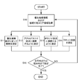
- FIG. 2 is a flowchart showing the operation of the radio broadcast receiving terminal 1 shown in FIG.
- START The control unit 2 of the radio broadcast receiving terminal 1 starts processing when the power is turned on or the navigation function and the radio viewing function are enabled.
- Step S1 The control unit 2 as an example of the current position specifying unit acquires information on the current position using a GPS antenna.
- Step S2 The control unit 2 as an example of a navigation unit acquires destination information input by the user operating the input unit 3.
- the stop point information may be acquired.
- the stop point information may be acquired.
- a case where only the stop point information is acquired will be described. To do.
- Step S3 The control unit 2 as an example of the communication control unit acquires the priority connection information input by the user operating the input unit 3.
- This priority connection information includes three types of connection setting modes: “analog radio priority”, “IP connection priority”, and “automatic”.
- This connection setting mode may be set by the user operating the input unit 3 in advance and may always perform the same operation, or a screen (not shown) that allows the user to select the connection setting mode at the start of radio broadcast viewing. It may be displayed on the video / audio output unit 5.
- “Analog radio priority” is a setting for preferential connection to analog radio broadcasting. When “analog radio priority” is selected, content is always received by analog radio broadcast in an area where analog radio broadcast can be received.
- IP connection priority is a setting for preferential connection to IP radio broadcasting. When “IP connection priority” is selected, in an area where reception of IP radio broadcasting is possible, connection is always performed with priority over IP radio broadcasting.
- “Random” is a setting for selecting a connection destination so that the number of times of connection switching is minimized. When “Random” is selected, the connection destination of each area is set to analog radio broadcasting or IP radio so that the number of connection switching is minimized in consideration of all reception conditions in the area from the current position to the destination or via value. Set to broadcast. Detailed processing at each setting will be described later.
- Step S4 The control unit 2 as an example of the navigation unit performs a route search based on the destination information acquired in step S2. This route search process is realized by the control unit 2 reading and executing the navigation program and navigation data described above.
- Step S5 The control unit 2 as an example of the receivable area determination unit, the current position acquired in step S1, the destination information acquired in step S2, and the IP radio broadcast connectable area MAP stored in the storage unit 6 And / or using the analog radio broadcast connectable area MAP, processing for specifying the IP connectable area and the analog radio receivable area from the current position to the destination is performed. Note that the connectable area information as a result specified in step S5 will be described later.
- Step S6 The control unit 2 as an example of the communication control unit sets a connection destination until the destination arrives according to the mode selected in step S3. The detailed process of step S6 will be described later.
- Step S7 The control unit 2 as an example of the communication control unit ends the process when connection destinations are determined in all areas until the process of step S6 arrives at the destination (END).
- processing for determining connection destinations in each area from the current location to the transit location and from the transit location to the destination may be performed. .
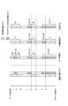
- FIG. 3 is a diagram showing an example of the receivable area information generated in step S5 of FIG.
- the user moves to the goal point B via points b to i while carrying the radio broadcast receiving terminal 1 at the start point A.
- the route guidance from the start point A to the goal point B is provided by the above-described navigation program performing a route search using the navigation data.
- From the start point A to the point b is an area where both IP radio broadcast and analog radio broadcast can be received. Further, from the point b to the point c, it is an area where the IP radio broadcast cannot be received but the analog radio broadcast can be received. Further, the area from the c point to the d point cannot receive any radio broadcast. From point d to point e, it is impossible to receive analog radio broadcasts, but it is an area where IP radio broadcasts can be received. From the e point to the f point, an analog radio broadcast can be received, but an IP radio broadcast cannot be received. The area from the point f to the point g cannot receive any broadcast.
- the area from the point h to the point i is an area where both IP radio broadcast and analog radio broadcast can be received. Finally, from the i point to the goal point B, the IP radio broadcast can be received, but the analog radio broadcast cannot be received.
- the radio broadcast receiving terminal 1 determines whether or not each receiving unit 4 can receive signals from the current position to the moving point (goal point B in the case of FIG. 3). These determinations are made by the control unit 2 reading and executing the above-described receivable area determination program from the storage unit 6.
- FIG. 4 is a diagram showing an example of a timeline based on priority connection information in the receivable area information shown in FIG.
- the timeline of the connection area uses the IP connectable area MAP and the analog radio receivable area MAP to time-sequentially receive and connect from the start point A that is the current position to the goal point B that is the destination or waypoint, This is a summary of connectable areas.
- each of the start points A, b to i, and the goal point B in FIG. 4 correspond to the points or points with the same reference numerals shown in FIG.
- connection settings are as follows: start point A to b point, b point to c point, e point to f point, h point to i point
- analog radio broadcasting is preferentially selected, and in each area between d point to e point, g point to h point, i point to goal point B, IP radio broadcasting is selected. Is done.
- IP connection priority IP radio broadcasting is preferentially selected for each area between the start point A to b point, d point to e point, and g point to goal point B.
- connection setting when “Random” is selected is set so that the number of times of connection switching is minimized in consideration of the reception status of the connectable area. Specifically, by receiving an analog radio broadcast in the area between the start points A to c, connection switching processing in this area does not occur. In addition, when an IP radio broadcast is received in the area between the g point and the goal point B, connection switching processing does not occur in this area. As described above, in the “Random” setting, the connection destination is determined in consideration of the reception status in the adjacent area.
- the number of connection switchings when each setting is made in the state of the connectable area shown in FIG. 4 is 5 for “Radio priority” and 4 for “IP connection priority”, but 3 for “Random”.
- the setting with the smallest number of connection switching is made.
- FIG. 5 is a flowchart showing details of the connection setting process performed in step S6 of FIG.
- START The control unit 2 as an example of the communication control unit performs the following process when the process of step S5 shown in FIG. 2 is completed.
- Step 10 The control unit 2 acquires the priority connection setting information input from the input unit 3 and the connectable area information specified in step S5. Based on the information acquired from the input unit 3, the control unit 2 proceeds to one of the following steps S11 to S14.
- Step S11 As a result of acquiring the connectable area information described above, the control unit 2 determines the connection destination according to the priority connection setting when it is determined that both areas are receivable (first area of claims). Set.
- Step S12 As a result of acquiring the above connectable area information, the control unit 2 determines that the area is an area where only analog radio broadcasting can be received (an example of the second area of the claims). Set to connect.
- Step S13 As a result of acquiring the above connectable area information, if the control unit 2 determines that the area can receive only the IP radio broadcast (an example of the second area of the claims), the control unit 2 performs the IP radio broadcast. Set to connect.
- Step S14 As a result of acquiring the connectable area information described above, the control unit 2 determines that it is an area in which any radio broadcast cannot be received (fourth area of the claims). In order to further reduce the number of scan processes in an area where the number of scan processes for connecting these can not be received, the number of scan processes is limited. For example, when the number of scan processes in an area where reception is impossible is set to 5 in advance, the setting is limited to a limit of 3 which is a smaller number of processes. The control unit 2 processes the connection destination according to the priority connection setting.
- Step S15 The control unit 2 repeats the processes from Steps S11 to S14 until connection setting is completed for all areas until reaching the destination or waypoint. When the connection setting is completed for all the areas up to the destination or waypoint, the control unit 2 ends the processing (END).
- FIG. 6 is a flowchart showing the connection switching operation of the radio broadcast receiving terminal 1 shown in FIG.
- the flowchart shown in FIG. 6 is a process for determining the timing for switching in the connection switching process determined based on the operation shown in FIG.
- START The control unit 2 starts the following process when the process shown in FIG. 2 is completed.
- Step S20 The control unit 2 as an example of the communication control unit performs connection switching processing according to a predetermined connection switching pattern when the reception status of the area changes. Specifically, it is in a state where analog radio broadcasting can be received and IP radio broadcasting can be received (hereinafter referred to as “analog radio: OK, IP: OK”). It is determined whether it corresponds to the connection switching pattern when analog radio: disabled, IP: enabled, or analog radio: enabled, IP: disabled. In (YES in step S20), the process proceeds to step S21. In other cases (NO in step S20), the process is performed according to the connection switching pattern described below.
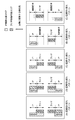
- FIG. 7 is a diagram showing a connection switching pattern performed in step S20 of the flowchart shown in FIG.
- the connection switching pattern shown in FIG. 7A is a case where the determination in step S20 is YES. That is, this is a pattern in which connection is switched to another radio broadcast when only one of the radio broadcasts can be received from an area that can be received by both analog radio broadcast and IP radio broadcast.
- the connection switching pattern shown in FIG. 7B is a connection when the analog radio is enabled, the IP is disabled, or the analog radio is disabled, the IP is enabled, and the analog radio is enabled and the IP is enabled.
- This is a switching pattern. That is, when moving from an area that can be received only by either analog radio broadcast or IP radio broadcast to an area that can be received by both radio broadcasts, the connection is switched to another radio broadcast.
- connection switching pattern shown in FIG. 7C is a connection switching pattern in a state where analog radio: possible, IP: impossible to analog radio: impossible, IP: acceptable, or analog radio: impossible, IP: acceptable
- analog radio possible
- IP impossible to analog radio
- IP acceptable
- IP acceptable
- IP acceptable
- the pattern shown in FIG. 7D is a connection switching pattern when moving from outside the connectable area into the connectable area.
- the pattern shown in FIG. 7E is a pattern for switching the connection when moving from the connectable area to the outside of the connectable area.
- step S20 the control unit 2 determines which pattern the reception status corresponds to, and performs processing for each corresponding pattern. Specifically, the control unit 2 proceeds to the process of step S21 when it corresponds to the pattern of FIG. 7A, and proceeds to the process of step S26 when it corresponds to the pattern of FIG. 7B. If the pattern in FIG. 7C corresponds to the pattern in FIG. 7C, the process proceeds to step S27. If the pattern in FIG. 7D corresponds to the pattern in FIG. 7D, the process proceeds to step S28. If it corresponds to the pattern, the process proceeds to step S29.
- Step S21 The control unit 2 as an example of a communication control unit detects a moving speed by an acceleration sensor (not shown) as an example of a speed detection unit. When the detection of the moving speed is completed by the acceleration sensor, the control unit 2 proceeds to step S22.
- the speed detection unit is not limited to an acceleration sensor, and may detect a speed by detecting a vehicle speed pulse.
- Step S22 The control unit 2 as an example of the communication control unit performs a moving speed determination. If it is faster than the predetermined speed, the process proceeds to step S23, and if it is slower, the process proceeds to step S24.
- the predetermined speed is, for example, 60 km / h, and the predetermined speed may be set in advance or may be directly input by the user via an operation unit (not shown).
- the predetermined speed is not limited to 60 km / h, and may be an arbitrary speed within a range of 4 km / h to 80 km / h, for example.
- Step S23 The control unit 2 as an example of the communication control unit sets the connection point before the connection disconnection point so that connection switching can be performed with a margin.
- the control unit 2 uses the points before the points b to h as the connection disconnection points shown in FIGS. 3 and 4 (for example, the goal point B via each point from the start point A).
- a switching point is set at the 200m point before passing b point, etc., and connection switching is performed with more margin than the above points serving as connection disconnection points. Note that the switching point is calculated in consideration of the moving speed of the radio broadcast receiving terminal 1.
- Step S24 The control unit 2 as an example of the communication control unit sets a connection switching point immediately before passing through the connection disconnection point. Specifically, for example, the control unit 2 moves from the point b immediately to the point h shown in FIGS. 3 and 4 to the immediately preceding point (for example, from the starting point A to the goal point B via each point). When passing b point in the situation to do, a switching point is set to a point 20m before passing b point). In addition, as an example immediately before the connection disconnection point here, it is a 20 m point before passing the connection disconnection point, but is not limited to this, for example, the point of the connection disconnection point according to the moving speed You may make it become arbitrary points from the range of 10m-100m etc. before passing. Note that the distance from the connection disconnection point for setting the switching point in step S24 is closer to the connection disconnection point side than the distance from the connection disconnection point for setting the switching point in step S23. It is preferable that it is set.
- Step S25 The control unit 2 as an example of the communication control unit performs connection switching processing while staying in the current area. Specifically, the control unit 2 sets a switching point in, for example, the area from the start to the b point shown in FIGS. 3 and 4 or the area from the h point to the i point.
- Step S26 The control unit 2 as an example of the communication control unit is connected after entering the next area according to the priority connection mode because the next area can be connected / received by either analog radio broadcast or IP radio broadcast. Perform the switching process. Specifically, for example, when staying between g point and h shown in FIGS. 3 and 4, control unit 2 sets a switching point in the area between h point and i point.
- Step S27 The control unit 2 as an example of the communication control unit moves from the current area to the next area because the next area cannot receive a radio broadcast unless it is a communication network different from the current area.
- connection switching processing is performed on the receiving unit 4 that can receive in the next area. Specifically, for example, when the control unit 2 stays in the area between the d point and the e point shown in FIGS. 3 and 4, the control unit 2 switches to the point 20 m immediately before entering the area between the e point and the f point. Set points.
- Step S28 Since the control unit 2 as an example of the communication control unit moves from an area where radio broadcast reception is currently impossible to an area where reception is possible, connection is made immediately before moving into the next area. Perform the switching process. Specifically, for example, when the control unit 2 moves from the area between the points f and g shown in FIGS. 3 and 4 to the area between the points g and h, the area between the points g and h is displayed. A switching point is set at a point 20 m immediately before entering.
- Step S29 Since the control unit 2 as an example of the communication control unit moves from an area where radio broadcast reception is currently possible to an area where reception is impossible, the current connection state is maintained until the connection is disconnected. . Specifically, the control unit 2, for example, even when moving from the area between the points b and c shown in FIGS. 3 and 4 to the area between the points c and d, the points b to c The reception of the radio broadcast is continued according to the setting of the receiving unit 4 when staying in the area between.
- Step S30 The control unit 2 as an example of the communication control unit determines whether or not it has arrived at the destination or the waypoint. If it has arrived (YES in step S30), the process ends (END). If it has not arrived (NO in step S30), the process returns to step S20.
- connection switching operation up to the goal point B has been described assuming that the start point A is the current location.
- the start point A may specify a point to pass through instead of the current location.
- content can be received by both analog radio broadcast and IP radio broadcast from the start point A to b point area and from the b point to c point area.
- the radio broadcast receiving terminal 1 transmits content transmitted through the first communication network (a communication network used when receiving an analog radio broadcast by a broadcast wave from the broadcast station 10).
- An input unit 3 for inputting information, a current position specifying unit (control unit 2) for specifying the current position, a route from the current position to the destination or waypoint, and guidance based on the searched route
- IP radio broadcasting IP radio transmitted
- the reception unit is predicted by determining the reception unit in advance when passing the estimated point.
- an appropriate connection destination can be set in advance according to the situation.
- it is not necessary to frequently perform connection switching processing since the connection destination is not frequently changed, delay processing associated with the change of the connection destination can be reduced, and the battery consumption of the apparatus can be suppressed.
- the radio broadcast receiving terminal 1 preferably includes a storage unit 6 in which the area information described above is stored.
- analog radio broadcasts stored in the storage unit 6 of the radio broadcast receiving terminal 1 itself can be received without acquiring information via an external network such as an IP communication network. It is also possible to specify a receivable area from the current location (current position) to the destination or waypoint from reliable area information and area information that can be received by IP radio broadcasting. In addition, it may be configured to be acquired from a server (not shown) that provides the area information described above, and in that case, even if the area information described above is not stored in the radio broadcast receiving terminal 1 itself, There is an effect that the area information can be appropriately acquired according to the current position of the receiving terminal 1.
- a communication control unit (control unit 2) is connected by a receivable area determination unit. It is an area where content can be received by both the first receiving unit (receiving unit 4 when receiving analog radio broadcasting) and the second receiving unit (receiving unit 4 when receiving IP radio broadcasting).
- the first receiving unit when receiving analog radio broadcast
- the second receiving unit when receiving IP radio broadcast
- the first receiving unit when receiving analog radio broadcast
- IP radio broadcast IP radio broadcast It is preferable to select one of the receiving units 4) when receiving.
- the communication control unit can connect from the current position to the destination or via In the route to the ground, the number of times of switching between the first receiver (receiver 4 when receiving analog radio broadcast) and the second receiver (receiver 4 when receiving IP radio broadcast) is minimized. It is preferable to select as follows.
- the communication control unit determines the receivable area determination unit.
- the first receiving unit when receiving an analog radio broadcast
- the second receiving unit when receiving an IP radio broadcast
- a communication control part (control part 2) is based on the connectable area information specified by determination of the receivable area determination part, and a predetermined connection switching pattern. Determining the timing of switching from one of the first receiving unit (receiving unit 4 when receiving analog radio broadcasting) or the second receiving unit (receiving unit 4 when receiving IP radio broadcasting) to the other Is preferred.
- the current position of the radio broadcast receiving terminal 1 is the first receiving unit (reception when receiving analog radio broadcast).
- Unit 4 and the second receiving unit (receiving unit 4 when receiving IP radio broadcast) from the first area determined to be able to receive content, the first receiving unit (analog radio) To the second area where it is determined that the content can be received only by either the receiving unit 4) for receiving the broadcast or the second receiving unit (receiving unit 4 for receiving the IP radio broadcast).
- the communication control unit (the first receiving unit or the second receiving unit determined to be able to receive content in the second area while staying in the first area) control 2) by which selected (e.g., FIG. 7 (A) connection switching patterns shown in) is preferred.
- the first area is entered.
- First receiving unit when receiving analog radio broadcast
- second receiving unit receiving IP radio broadcast
- the communication control unit control unit 2
- connection to the receiving unit 4 that can receive within the first area is established. By switching, it is possible to reduce the possibility that the received electric field strength is suddenly reduced.
- the current position of the radio broadcast receiving terminal 1 is changed from the second area described above to the content in the second area.
- the communication control unit selects the reception unit 4 that is determined to be able to receive content in the third area immediately before the transmission (for example, the connection switching pattern shown in FIG. 7C). Is preferred.
- switching the connection immediately before moving from the second area to the third area also provides an effect that appropriate connection switching can be performed in accordance with a change in reception status. .
- the current position of the radio broadcast receiving terminal 1 is the first receiving unit (reception when receiving analog radio broadcast).
- Unit 4 and the second receiving unit (receiving unit 4 in the case of receiving IP radio broadcast), the first receiving unit (analogue) from the fourth area determined to be incapable of receiving content.
- the communication control unit determines that the receiving unit 4 is determined to be capable of receiving content in the fifth area within a predetermined range before entering the fifth area. Which more selective (e.g., connection switching pattern shown in FIG. 7 (D)) is preferred.
- connection switching pattern in the radio broadcast receiving terminal 1 when moving from the fifth area described above to the fourth area described above, content is actually received. Until the communication control unit (control unit 2) receives the signal representing the content in either the first reception unit or the second reception unit connected in the fifth area until the communication control unit (control unit 2) can receive the communication (for example, The connection switching pattern shown in FIG.
- radio broadcasts can be received in consideration of actual reception conditions even after passing through a point estimated to be a receivable area.
- the communication control unit (control unit 2) limit the number of times to a number smaller than the predetermined number set as the number of scan processes.
- the number of scan processes for searching for whether or not radio broadcasts can be received in an area where radio broadcasts cannot be received is not unnecessarily increased. That is, when the upper limit of the number of scan processes is preset, the number of scan processes can be reduced by limiting the value to a value smaller than the set value, and the power consumption of the apparatus can be suppressed. Also play.
- a radio broadcast receiving terminal 1 is equipped with the moving speed of the radio broadcast receiving terminal 1 or the radio broadcast receiving terminal 1 in addition to any of the configurations of the radio broadcast receiving terminal 1 described above.
- the communication control unit receives the first reception unit (analog radio broadcast) based on the speed detected by the speed detection unit. It is preferable to determine the timing for switching from one of the receiving unit 4) or the second receiving unit 4 (receiving unit 4 when receiving IP radio broadcast) to the other.
- the communication control unit includes the first area described above.
- the radio broadcast receiving terminal 1 or the mobile body equipped with the radio broadcast receiving terminal 1 enters the first area and the second area when passing through the second area described above, It is preferable to select in advance from either the first receiving unit or the second receiving unit determined to be able to receive content in both the first area and the second area.
- the receiving unit 4 that can receive signals in both the first area and the second area is selected, the number of connection switchings in the sections of the first area and the second area is reduced. There is also an effect that it can be done.
- the connection switching method of the radio broadcast receiving terminal 1 includes an input unit 3, a current position specifying unit (control unit 2), a navigation unit (control unit 2), and a first communication.
- a first receiving unit (receiving unit 4 when receiving analog radio broadcast) that receives a signal representing content transmitted by a network (communication network when receiving an analog radio broadcast by a broadcast wave from the broadcast station 10)
- a second signal that receives a signal representing content transmitted by a second communication network (a communication network for receiving an IP radio broadcast transmitted from the service provider apparatus 20) different from the first communication network.
- Connection switching method used for the radio broadcast receiving terminal 1 including at least a receiving unit (receiving unit 4 when receiving IP radio broadcast), a receivable area determining unit, and a communication control unit (control unit 2).
- the destination information or waypoint information is acquired by a signal input by the user via the input unit 3, and the navigation unit (control unit 2) routes based on the current position information and the destination or waypoint information.
- the first receiving unit (receiving unit 4 when receiving an analog radio broadcast) in the route from the current position to the destination or the waypoint is guided based on the searched route.
- area information indicating whether or not content can be received by at least one of the second receiving units (receiving unit 4 when receiving IP radio broadcast) is acquired, and the first information is obtained based on the area information.
- control unit 2 determines whether the content is received based on the determination by the receivable area determining unit. It is to determine either the first receiver or the second receiver as a receiving section for receiving.
- the reception field strength is predicted to be sharply reduced based on the determination of the receivable area, and the reception unit is determined in advance when passing the estimated point.
- an appropriate connection destination can be set according to the reception status.
- it is not necessary to frequently perform connection switching processing since the connection destination is not frequently changed, delay processing associated with the change of the connection destination can be reduced, and the battery consumption of the apparatus can be suppressed.
- connection switching program for the radio broadcast receiving terminal 1 provides a computer used as the radio broadcast receiving terminal 1 to destination information or a destination input by the user via the input unit 3.
- the receiving area determining means for determining whether or not the signal representing the content is receivable is received as a receiving means for receiving the signal representing the content based on the determination by the receivable area determining means. It is made to function as a communication control means (control unit 2) that decides either the first receiving means or the second receiving means.
- the reception field strength is predicted to be sharply reduced based on the determination of the receivable area, and the reception unit is determined in advance when passing the estimated point.
- an appropriate connection destination can be set according to the reception status.
- it is not necessary to frequently perform connection switching processing since the connection destination is not frequently changed, delay processing associated with the change of the connection destination can be reduced, and the battery consumption of the apparatus can be suppressed.
- the radio broadcast receiving terminal 1 is provided with reception field strength measuring means capable of measuring the actual reception field strength, and the number of scan processes for connection in each of the receivable area and the unreceivable area shown in FIG. 4 is set. Or may be adjusted. Specifically, the number of scans is set to 2 to 3 in an area where analog radio broadcast or IP radio broadcast cannot be received, and the number of scans is initially set to 10 in an area where reception is possible.
- a predetermined value for example, 2
- the number of scan processes may not be limited.
- a predetermined value for example, 2 may be subtracted from the initial scan count or the scan process may not be performed.
- the comparison processing of the detected received electric field strength and the threshold value is performed at a predetermined timing, the quality of the reception sensitivity is determined based on a predetermined number of comparison results, and the predetermined value is subtracted or added to the initial value described above. Good.
- the upper limit of the number of scans is changed according to the actual reception sensitivity, so even if there is a difference between the connectable area information and the actual reception sensitivity status, the preset number of scan processes is set appropriately. The power consumption can be effectively suppressed by adjusting or canceling the scan process.
- control unit 2 extracts all the combination patterns of the reception unit 4 that can receive signals representing content between the current position and the destinations based on the connectable area information.
- a combination pattern including a section in which the continuous viewing time of either analog radio broadcasting or IP radio broadcasting is the longest among the patterns may be adopted.
- the radio broadcast receiving terminal 1 may not have all the connection switching patterns shown in FIGS. 7A to 7E.
- the IP radio broadcast may be connectable only in the area where the analog radio broadcast can be received.
- Radio broadcast receiving terminal an example of an information terminal
- 2 Control part (an example of a navigation part, a receivable area determination part, a communication control part, a navigation means, a receivable area determination means, a communication control means) 3...
- Input unit 4
- Reception unit an example of a first reception unit, an example of a second reception unit
- 5 An audio / video output unit, 6. ..Broadcasting station, 20 ... Service provider equipment
Landscapes
- Engineering & Computer Science (AREA)
- Computer Networks & Wireless Communication (AREA)
- Signal Processing (AREA)
- Computer Security & Cryptography (AREA)
- Circuits Of Receivers In General (AREA)
- Navigation (AREA)
- Two-Way Televisions, Distribution Of Moving Picture Or The Like (AREA)
- Mobile Radio Communication Systems (AREA)
Abstract
電波の受信状況を予め考慮して接続先を選択すると共に、受信状況に応じて適切な接続先に切り替えること。 第1の通信網によって送信されるコンテンツを表す信号を受信する第1の受信部(受信部4)、第1の通信網とは異なる第2の通信網によって送信されるコンテンツを表す信号を受信する第2の受信部(受信部4)、目的地等を入力させるための入力部3、現在位置を特定する現在位置特定部(制御部2)、現在位置から目的地等までの経路を探索し、誘導するナビゲーション部(制御部2)、現在位置から目的地等までの経路で、第1の受信部または第2の受信部でコンテンツの受信可否を判定する受信可能エリア判定部(制御部2)、上述した経路上でコンテンツを受信する受信部として第1の受信部または第2の受信部のいずれかに決定する通信制御部(制御部2)と、を備えるラジオ放送受信端末1(情報端末)とする。
Description
本発明は、情報端末、接続切り替え方法、および接続切り替えプログラムに関する。
近年、デジタルテレビ放送やアナログテレビ放送を受信できる携帯型のテレビ放送受信機や、これらの放送を視聴することができる多機能型のカーナビゲーション装置などが知られている。これらの装置においてデジタルテレビ放送やアナログテレビ放送を移動しながら視聴すると、電波の受信状況が悪化して画面表示や音声出力に乱れが生じる、またはコンテンツを視聴することができなくなることがある。
このような課題に対して、受信電界強度を検出し、現在接続している通信手段から他の安定してコンテンツを受信できる別の通信手段に接続を切り替える技術が提案されている(たとえば特許文献1参照)。また、それぞれの通信手段の受信可能なエリア情報を予め装置内に保持しておき、これらのエリア情報および実際の電波の受信状況を考慮して、どの通信網に接続するかを決定する技術が提案されている(たとえば特許文献2参照)。
しかしながら、上述した技術には、次のような課題がある。すなわち、特許文献1に開示される技術では、リアルタイムに受信電界強度を測定する移動型の受信機であるため、受信電界強度が急激に低下した場合には、接続切り替え処理時に発生するコンテンツの整合性を保つための遅延処理などが間に合わず、画面が表示されない、または音声出力が停止する可能性がある。また、受信状況によっては、接続先が頻繁に切り替わる可能性がある。また、接続先が頻繁に変更されると上述の遅延処理等が増加し、装置の電池消耗が激しくなる。
また、特許文献2に開示される技術では、受信可能なエリア情報を考慮してはいるが、やはり実際の電波の受信状況により最終的な接続切り替えを行っているため、受信電界強度が急激に低下した場合には、接続切り替え処理時に発生するコンテンツの整合性を保つための遅延処理などが間に合わず、画面が表示されない、または音声出力が停止する可能性がある。また、受信状況によっては、接続先が頻繁に切り替わる可能性がある。また、接続先が頻繁に変更されると上述の遅延処理等が増加し、装置の電池消耗が激しくなる。また、特許文献2に開示される技術は、デジタルテレビ放送またはアナログテレビ放送の受信状況の一方が悪いときは、他方に切り替えることになる。ここで、仮にアナログテレビ放送の受信状況が悪いときにデジタルテレビ放送に切り替えたとしても、デジタル信号のエラー訂正能力の限界を超えるほど受信環境が悪い場合には、受信品質レベルがアナログテレビ放送を受信しているときよりも更に低下する場合がある。
そこで、本発明は、上述した課題に鑑み、電波の受信状況を予め考慮して接続先を選択すると共に、受信状況に応じて適切な接続先に切り替える情報端末、接続切り替え方法、および接続切り替えプログラムを提供することを目的とする。
本発明の一側面である情報端末は、第1の通信網によって送信されるコンテンツを表す信号を受信する第1の受信部と、第1の通信網とは異なる第2の通信網によって送信されるコンテンツを表す信号を受信する第2の受信部と、目的地情報または目的地までの経由地情報を入力するための入力部と、現在位置を特定する現在位置特定部と、現在位置から目的地または経由地までの経路を探索し、探索された経路に基づいて誘導するナビゲーション部と、現在位置から目的地または経由地までの経路間において、第1の受信部または第2の受信部の少なくとも一方でコンテンツ表す信号の受信が可能であるか否かを示すエリア情報を取得し、取得したエリア情報に基づいて第1の受信部または第2の受信部の少なくとも一方でコンテンツを表す信号の受信が可能であるか否かを判定する受信可能エリア判定部と、受信可能エリア判定部の判定に基づいて、コンテンツを表す信号を受信する受信部として第1の受信部または第2の受信部のいずれかに決定する通信制御部と、を備えるものである。
また、本発明の一側面である情報端末は、上述した情報端末の構成に加えて、エリア情報が記憶されている記憶部を備えていることが好ましい。
また、本発明の一側面である情報端末では、上述した情報端末の構成のいずれかに加えて、コンテンツを表す信号を第1の受信部または第2の受信部のいずれかで優先的に受信させる接続設定を通信制御部に指示するための選択指示情報の入力が可能であり、通信制御部は、受信可能エリア判定部により第1の受信部および第2の受信部のいずれでもコンテンツを表す信号の受信が可能であるエリアであると判定された区間は、入力部から入力された選択指示情報に基づいて第1の受信部または第2の受信部のいずれかを優先して選択することが好ましい。
また、本発明の一側面である情報端末では、上述した情報端末の構成のいずれかに加えて、通信制御部は、現在位置から目的地または経由地までの経路において、第1の受信部と第2の受信部を切り替える回数が最も少なくなるように選択することが好ましい。
また、本発明の一側面である情報端末では、上述した情報端末の構成のいずれかに加えて、通信制御部は、受信可能エリア判定部の判定により特定された接続可能エリア情報に基づいて、第1の受信部または第2の受信部のいずれか一方から他方へと切り替えるタイミングを決定することが好ましい。
さらに、本発明の一側面である情報端末では、通信制御部は、受信可能エリア判定部の判定により特定された接続可能エリア情報および所定の接続切り替えパターンに基づいて、上述したタイミングを決定することが好ましい。
また、本発明の一側面である情報端末における上述した所定の接続切り替えパターンとして、情報端末の現在位置が、第1の受信部および第2の受信部のいずれでもコンテンツを表す信号の受信が可能であると判定された第1のエリアから、第1の受信部または第2の受信部のいずれかでのみコンテンツを表す信号の受信が可能であると判定された第2のエリアへ移動する場合に、第1のエリア内に滞在する間に第2のエリアにおいてコンテンツを表す信号の受信が可能であると判定された第1の受信部または第2の受信部のいずれかを通信制御部により選択するものが好ましい。
また、本発明の一側面である情報端末における上述した所定の接続切り替えパターンとして、情報端末の現在位置が、第1の受信部または第2の受信部のいずれかでのみコンテンツを表す信号の受信が可能であると判定された第2のエリアから、第1の受信部および第2の受信部のいずれでもコンテンツを表す信号の受信が可能であると判定された第1のエリアへ移動する場合に、第1のエリアへ移動後に第1の受信部または第2の受信部のいずれかを通信制御部により選択するものが好ましい。
また、本発明の一側面である情報端末における上述した所定の接続切り替えパターンとして、情報端末の現在位置が、第1の受信部または第2の受信部のいずれかでのみコンテンツを表す信号の受信が可能であると判定された第2のエリアから、第2のエリアでコンテンツを表す信号の受信が可能であると判定された受信部とは異なる受信部でのみコンテンツを表す信号の受信が可能であると判定された第3のエリアへ移動する場合に、第2のエリアから第3のエリアへ移動する直前に第3のエリア内でコンテンツを表す信号の受信が可能であると判定された第1の受信部または第2の受信部のいずれかを通信制御部により選択するものが好ましい。
また、本発明の一側面である情報端末における上述した所定の接続切り替えパターンとして、情報端末の現在位置が、第1の受信部および第2の受信部のいずれでもコンテンツを表す信号の受信が不可能であると判定された第4のエリアから、第1の受信部または第2の受信部の少なくとも一方でコンテンツを表す信号の受信が可能であると判定された第5のエリアへ移動する場合に、第5のエリア内に進入する前の所定範囲において、第5のエリアにおいてコンテンツを表す信号の受信が可能であると判定された第1の受信部または第2の受信部のいずれかを通信制御部により選択するものが好ましい。
また、本発明の一側面である情報端末における上述した所定の接続切り替えパターンとして、情報端末の現在位置が、第1の受信部または第2の受信部の少なくとも一方でコンテンツを表す信号の受信が可能であると判定された第5のエリアから、第1の受信部および第2の受信部のいずれでもコンテンツを表す信号の受信が不可能であると判定された第4のエリアへ移動する場合に、実際にコンテンツを表す信号の受信ができなくなるまで、第5のエリア内で接続している第1の受信部または第2の受信部のいずれかでコンテンツを表す信号の受信を行うものが好ましい。
さらに、上述した第4のエリア内でのコンテンツを表す信号を受信するためのスキャン処理回数として設定された所定回数よりも少ない回数に通信制御部により制限するものが好ましい。
また、本発明の一側面である情報端末は、上述した情報端末の構成のいずれかに加えて、情報端末の移動速度もしくは情報端末を搭載している移動体の移動速度を検出する速度検出部を備え、通信制御部は、速度検出部により検出された速度に基づいて第1の受信部または第2の受信部のいずれか一方から他方へと切り替えるタイミングを決定するものが好ましい。
また、本発明の一側面である情報端末では、上述した情報端末の構成のいずれかに加えて、通信制御部は、情報端末の現在位置が、第1のエリアと、第2のエリアとを通過する場合に、第1のエリアまたは第2のエリアのいずれかに進入する前に、第1のエリアおよび第2のエリアの両方でコンテンツを表す信号の受信が可能と判定された第1の受信部または第2の受信部のいずれかを予め選択することが好ましい。
また、本発明の一側面である接続切り替え方法は、入力部と、現在位置特定部と、ナビゲーション部と、第1の通信網によって送信されるコンテンツを表す信号を受信する第1の受信部と、第1の通信網とは異なる第2の通信網によって送信されるコンテンツを表す信号を受信する第2の受信部と、受信可能エリア判定部と、通信制御部と、を少なくとも備えた情報端末に用いられる接続切り替え方法であって、入力部を介してユーザにより入力される信号により目的地情報または経由地情報を取得し、現在位置特定部により現在位置情報を取得し、ナビゲーション部が現在位置情報と、目的地または経由地情報とに基づいて経路を探索し、探索された経路に基づいて誘導し、受信可能エリア判定部が経路間において、第1の受信部または第2の受信部の少なくとも一方でコンテンツを表す信号の受信が可能であるか否かを示すエリア情報を取得し、取得したエリア情報に基づいて第1の受信部または第2の受信部の少なくとも一方でコンテンツを表す信号の受信が可能であるか否かを判定し、通信制御部が受信可能エリア判定部の判定に基づいて、コンテンツを表す信号を受信する受信部として第1の受信部または第2の受信部のいずれかに決定するものである。
また、本発明の一側面である接続切り替えプログラムは、コンピュータを、入力部を介してユーザにより入力された目的地情報または目的地までの経由地情報を取得する手段、現在位置を検出する現在位置特定手段、現在位置から目的地または経由地までの経路を探索し、誘導するナビゲーション手段、目的地または経由地までの経路間において、第1の通信網によって送信されるコンテンツを表す信号を受信する第1の受信手段または第1の通信網とは異なる第2の通信網によって送信されるコンテンツを表す信号を受信する第2の受信手段の少なくとも一方でコンテンツを表す信号の受信が可能であるか否かを示すエリア情報を取得し、取得したエリア情報に基づいて第1の受信手段または第2の受信手段の少なくとも一方でコンテンツを表す信号の受信が可能であるか否かを判定する受信可能エリア判定手段、受信可能エリア判定手段の判定に基づいて、コンテンツを表す信号を受信する受信手段として第1の受信手段または第2の受信手段のいずれかに決定する通信制御手段として機能させるものである。
本発明によれば、電波の受信状況を予め考慮して接続先を選択すると共に、受信状況に応じて適切な接続先に切り替える情報端末、接続切り替え方法、および接続切り替えプログラムを提供することができる。
本発明に係る情報端末、接続切り替え方法、および接続切り替えプログラムの一実施例について、ラジオ放送受信端末1を例示して説明する。なお、本発明に係る情報端末は、ラジオ放送受信端末1に限らず、2種類の通信手段、またはそれ以上の通信手段により同様のコンテンツを受信可能な携帯型のテレビ放送受信端末や、多機能型のカーナビゲーション装置、携帯電話などであってもよい。なお、以下の実施例でいう「コンテンツ」とは、狭義にはデジタル信号であるかアナログ信号で供給されるかを問わず、音声データ、音楽データ、動画データ、画像データが含まれるものであり、広義には放送局10やサービス事業者装置20が提供する上述した各種データを一体として提供する放送チャンネル自体を指すものである。
図1は、本発明に係る情報端末の一実施例としてのラジオ放送受信端末1と、このラジオ放送受信端末1にアナログラジオ放送によってコンテンツを提供する放送局10と、このラジオ放送受信端末1に上述したアナログラジオ放送で提供されるコンテンツと同様のコンテンツをIPパケットに変換して提供する、いわゆるIP再送信技術を利用したラジオ放送(以下、このような形式によるラジオ放送のことを便宜的に「IPラジオ放送」という)を行うサービス事業者装置20とを含むネットワーク構成例を示す図である。本実施例のラジオ放送受信端末1では、アナログラジオ放送およびIPラジオ放送にそれぞれ接続可能であるエリアを考慮したマップを予め保持している。IPラジオ放送は、著作権法上の問題から原則としてアナログラジオ放送接続可能エリアのみ接続可能であるが、本実施例では、アナログラジオ放送で接続不可能であってもIPラジオ放送で接続可能であるエリアを含めている。なお、本実施例では、同様のコンテンツをラジオ放送受信端末1に供給する手段は、放送局10およびサービス事業者装置20の2種類として構成されるが、2種類以上の複数の通信網によって同様のコンテンツをラジオ放送受信端末1に提供するように構成されてもよい。
また、本実施例でいう「同様のコンテンツ」とは、内容的に完全な同一性を必須要件とするものではない。たとえば、アナログラジオ放送で提供する音声データや音楽データと共に、画像データや動画データが新たに付加されたコンテンツ群をIPラジオ放送として提供している場合であっても、これらを「同様のコンテンツ」として取り扱う。また、アナログラジオ放送で提供するコンテンツの一部のみをIPラジオ放送によって提供する場合であっても、これらを「同様のコンテンツ」として取り扱う。なお、「同様のコンテンツ」は、同一であるコンテンツを排除するものではなく、本実施例においてアナログラジオ放送で提供するコンテンツと同一であるコンテンツがIPラジオ放送で提供されてももちろんよい。
ラジオ放送受信端末1は、図1に示すように制御部2、入力部3、受信部4、映像音声出力部5、記憶部6などを主要な構成要素としている。ここで、現在位置特定部、受信可能エリア判定部、通信制御部の一例としての制御部2は、たとえばCPU(Central Processing Unit)などで構成され、記憶部6に格納されているOSや各種プログラムに応じて、各種演算処理を実行するとともに、ラジオ放送受信端末1の各部からの出力信号などによりラジオ放送受信端末全体を制御する中央処理装置である。
入力部3は、ユーザからの操作指示情報を入力させることができる。入力部3は、ユーザが操作することにより、IPラジオ放送またはアナログラジオ放送のいずれかへの接続指示情報やこれらの接続切り替え指示情報などを行うための電気信号を制御部2へ出力することができる。また、入力部3は、ユーザの操作により、IPラジオ放送またはアナログラジオ放送のいずれかを優先して接続するモードを選択する選択指示情報や、おまかせモードを選択するための選択指示情報を制御部2へ出力することができる。
第1の受信部および第2の受信部の一例としての受信部4は、放送局10から提供されるアナログラジオ放送信号、サービス事業者装置20から提供されるデジタル信号、GPS(Global Positioning System)衛星から供給されるGPS信号を受信する専用のアンテナやチューナにより構成される。また、受信部4は、受信した信号を増幅し復調する機能を有していてもよい。本実施例では、受信部4が第1の受信部の一例として機能するときは、アナログラジオ放送を放送局10から受信し、第2の受信部の一例として機能するときはサービス事業者装置20などから構成されるインターネットを経由してからIPラジオ放送を受信する。なお、受信部4は、GPS衛星からの信号を受信する機能、放送局10からのアナログラジオ放送を受信する機能、サービス事業者装置からIPラジオ放送を受信する機能のそれぞれを別々の装置で構成する、またはいずれか一つの機能のみを別の装置として構成してもよい。
映像音声出力部5は、たとえば液晶ディスプレイなどを有していて、受信部4で受信した信号に基づいてIPラジオ放送の画像データを表示する、または動画データを再生することができる。また、映像音声出力部5は、たとえばスピーカなどを有していて、受信部4により受信した信号に基づいて音声データを再生する。
記憶部6は、たとえば、EEPROM(Electrically Erasable and Programmable Read Only Memory)やフラッシュメモリ、制御部2がワークエリアとして使用するRAM(Randam Access Memory)などの記憶媒体で構成される。記憶部6には、ラジオ放送受信端末1を制御するOS(Operating System)や、ナビゲーションプログラムおよびナビゲーションデータの他に、受信可否判定プログラム、IPラジオ放送接続可能エリアMAP、アナログラジオ放送接続可能エリアMAPなどが記憶されている。
ここで、IPラジオ放送接続可能エリアMAPまたはアナログラジオ放送接続可能エリアMAPとは、IPラジオ放送またはアナログラジオ放送を受信できるエリア情報の集合体により構成される。なお、これらのエリア情報は、所定の区画単位毎のIPラジオ放送またはアナログラジオ放送の受信可否を示す情報である。これらのIPラジオ放送接続可能エリアMAPとアナログラジオ放送接続可能エリアMAPを構成するエリア情報は、ラジオ放送受信端末1の製造出荷時に予め記憶されている、または受信部4を介してIPネットワーク網と接続するとともに、エリア情報をダウンロードして記憶部6に記憶するようにしてもどちらでもよい。また、受信部4を介してIPネットワーク網と接続し、IPラジオ放送接続可能エリアMAPとアナログラジオ放送接続可能エリアMAPの更新情報を取得するようにしてもよい。なお、本発明の記憶部6の構成は、EEPROMやフラッシュメモリに限らず、必要に応じて、ROM(Read Only Memory)、HDD(Hard Disk Drive)などを含んでもよい。
続いて、ラジオ放送受信端末1の動作について説明する。図2は、図1に示すラジオ放送受信端末1の動作を示すフローチャートである。
START:ラジオ放送受信端末1の制御部2は、電源が投入またはナビゲーション機能およびラジオの視聴機能が有効にされると処理を開始する。
ステップS1:現在位置特定部の一例としての制御部2は、GPSアンテナにより現在位置に関する情報を取得する。
ステップS2:ナビゲーション部の一例としての制御部2は、ユーザが入力部3を操作することで入力された目的地情報を取得する。なお、このステップ2において目的地情報に加えて経由地情報も入力された場合にはその経由地情報も取得するようにしてもよいが、以下の例では目的地情報のみを取得した場合を説明する。
ステップS3:通信制御部の一例としての制御部2は、ユーザが入力部3を操作して入力された優先接続情報を取得する。この優先接続情報には「アナログラジオ優先」、「IP接続優先」、「おまかせ」の3種類の接続設定モードが含まれている。この接続設定モードは、事前にユーザが入力部3を操作して設定し、常に同じ動作をするようにしてもよいし、ラジオ放送の視聴開始時に接続設定モードを選択できる画面(不図示)を映像音声出力部5に表示してもよい。
ここで「アナログラジオ優先」とは、アナログラジオ放送に優先的に接続する設定である。「アナログラジオ優先」が選択されると、アナログラジオ放送の受信が可能なエリアである場合には、必ずアナログラジオ放送によりコンテンツを受信する。また、「IP接続優先」とは、IPラジオ放送に優先的に接続する設定である。「IP接続優先」が選択されると、IPラジオ放送の受信が可能なエリアである場合には、必ずIPラジオ放送に優先して接続して受信する。また「おまかせ」とは、接続切り替え回数が最も少なくなるように接続先を選択する設定である。「おまかせ」が選択されると、現在位置から目的地または経由値までのエリアでの受信状況をすべて考慮して接続切り替え回数が最も少なくなるようにエリア毎の接続先をアナログラジオ放送またはIPラジオ放送に設定する。なお、各設定時の詳細な処理については後述する。
ステップS4:ナビゲーション部の一例としての制御部2は、ステップS2において取得した目的地情報に基づいてルート探索を行う。なお、このルート探索処理は、制御部2が上述したナビゲーションプログラムおよびナビゲーションデータを読み出して実行することにより実現される。
ステップS5:受信可能エリア判定部の一例としての制御部2は、ステップS1において取得した現在位置とステップS2において取得した目的地情報と、記憶部6に記憶されているIPラジオ放送接続可能エリアMAPおよび/またはアナログラジオ放送接続可能エリアMAPとを利用し、現在位置から目的地までのIP接続可能エリアおよびアナログラジオ受信可能エリアを特定する処理を行う。なお、ステップS5で特定した結果の接続可能エリア情報については後述する。
ステップS6:通信制御部の一例としての制御部2は、ステップS3において選択されたモードに従って、目的地に到着するまでの接続先の設定を行う。なお、ステップS6の詳細な処理については後述する。
ステップS7:通信制御部の一例としての制御部2は、ステップS6の処理を目的地に到着するまでのすべてのエリアにおいて接続先が決定されると処理を終了する(END)。なお、ステップS2において目的地情報に加えて経由地情報を取得した場合には、現在地から経由地まで、経由地から目的地までの各エリアにおいて接続先を決定する処理を行うようにしてもよい。
図3は、図2のステップS5で生成される受信可能エリア情報の一例を示す図である。ユーザは、スタート地点Aにおいてラジオ放送受信端末1を携帯しながら、bポイント~iポイントまでを経由してゴール地点Bに移動する。なお、このスタート地点Aからゴール地点Bまでの経路案内は、上述したナビゲーションプログラムがナビゲーションデータを用いて経路探索を行って提供される。
図3に示すように、スタート地点AからbポイントまではIPラジオ放送およびアナログラジオ放送共に受信が可能なエリアである。また、bポイントからcポイントまではIPラジオ放送は受信が不可能であるが、アナログラジオ放送の受信が可能であるエリアである。また、cポイントからdポイントまではいずれのラジオ放送も受信できないエリアである。そして、dポイントからeポイントまではアナログラジオ放送の受信は不可能であるが、IPラジオ放送の受信は可能なエリアである。eポイントからfポイントまではアナログラジオ放送の受信は可能であるが、IPラジオ放送の受信が不可能なエリアである。そして、fポイントからgポイントまではいずれの放送も受信できないエリアである。そして、gポイントからhポイントまでは、IPラジオ放送の受信は不可能であるが、アナログラジオ放送の受信は可能であるエリアである。そして、hポイントからiポイントまではIPラジオ放送およびアナログラジオ放送共に受信が可能なエリアである。最後に、iポイントからゴール地点BまではIPラジオ放送は受信が可能であるが、アナログラジオ放送の受信が不可能であるエリアである。
このように、ラジオ放送受信端末1は、現在位置から移動する地点(図3の場合はゴール地点B)までの各受信部4での受信可否判定を行う。なお、これらの判定は、制御部2が、記憶部6から上述した受信可能エリア判定プログラムを読み出して実行することにより判定する。
図4は、図3に示す受信可能エリア情報において優先接続情報によるタイムラインの一例を示す図である。接続エリアのタイムラインは、IP接続可能エリアMAPとアナログラジオ受信可能エリアMAPにより、現在位置であるスタート地点Aから目的地または経由地であるゴール地点Bまでの受信・接続状況を時系列にし、接続可能エリアをまとめたものである。
図4の「接続可能エリア」に示すように、スタート地点Aからゴール地点Bまでの各エリアでの受信状況が示されている。なお、図4のスタート地点A、b~iの各ポイント、ゴール地点Bは、図3に示す同一の符号の地点またはポイントにそれぞれ対応している。
この接続可能エリアの情報に基づいて、たとえば「ラジオ優先」が選択された場合の接続設定は、スタート地点A~bポイント,bポイント~cポイント,eポイント~fポイント,hポイント~iポイント間の各エリアについてはアナログラジオ放送が優先的に選択され、dポイント~eポイント、gポイント~hポイント,iポイント~ゴール地点B間の各エリアではアナログ放送が受信できないため、IPラジオ放送が選択される。また、「IP接続優先」が選択された場合の接続設定は、スタート地点A~bポイント,dポイント~eポイント,gポイント~ゴール地点B間の各エリアでは、IPラジオ放送が優先的に選択され、bポイント~cポイント,eポイント~fポイント間の各エリアでは、IPラジオ放送が受信できないため、アナログラジオ放送が選択される。また、「おまかせ」が選択された場合の接続設定は、接続可能エリアの受信状況を考慮し、最も接続切り替え回数が少なくなるように設定される。具体的には、スタート地点A~cポイント間のエリアではアナログラジオ放送を受信することでこのエリア内での接続切り替え処理が発生しなくなる。また、gポイント~ゴール地点B間のエリアではIPラジオ放送を受信することで、このエリア内での接続切り替え処理が発生しなくなる。このように「おまかせ」設定では、隣接するエリアでの受信状況を考慮して接続先を決定している。これにより、図4に示す接続可能エリアの状況において各設定をした場合での接続切り替え回数は、「ラジオ優先」では5回、「IP接続優先」では4回となるが、「おまかせ」では3回となり、最も接続切り替え回数が少ない設定がなされることになる。
図5は、図2のステップS6において行われる接続設定処理の詳細を示すフローチャートである。
START:通信制御部の一例としての制御部2は、図2に示すステップS5の処理が完了すると以下の処理を行う。
ステップ10:制御部2は、入力部3から入力された優先接続設定情報およびステップS5で特定された接続可能エリア情報を取得する。制御部2は、入力部3から取得した情報により、以下のステップS11~ステップS14のいずれかの処理へと移行する。
ステップS11:制御部2は、上述の接続可能エリア情報を取得した結果、両方とも受信可能であるエリア(請求項の第1のエリア)と判定した場合には、優先接続設定にしたがって接続先を設定する。
ステップS12:制御部2は、上述の接続可能エリア情報を取得した結果、アナログラジオ放送のみ受信可能であるエリア(請求項の第2のエリアの一例)と判定した場合には、アナログラジオ放送に接続するように設定する。
ステップS13:制御部2は、上述の接続可能エリア情報を取得した結果、IPラジオ放送のみ受信可能であるエリア(請求項の第2のエリアの一例)と判定した場合には、IPラジオ放送に接続するように設定する。
ステップS14:制御部2は、上述の接続可能エリア情報を取得した結果、いずれのラジオ放送も受信不可能であるエリア(請求項の第4のエリア)と判定した場合には、このエリア内での接続するためのスキャン処理回数を受信不可能であるエリア内におけるスキャン処理回数をより少なくするために、スキャン処理回数を制限する。たとえば、受信不可能であるエリア内におけるスキャン処理回数が予め5回と設定されていた場合には、それより少ない処理回数である3回までに制限する設定に変更するなどである。なお、制御部2は、接続先は優先接続設定に従って処理する。
ステップS15:制御部2は、目的地または経由地に到達するまでのエリア全てについて接続設定が完了するまでステップS11~S14までの処理を繰り返す。制御部2は、目的地または経由地に到達するまでのエリア全てについて接続設定が完了すると、処理を終了する(END)。
続いて、ラジオ放送受信端末1の接続切り替え動作について説明する。図6は、図1に示すラジオ放送受信端末1の接続切り替え動作を示すフローチャートである。この図6に示すフローチャートは、図2に示す動作に基づいて決定された接続切り替え処理の際の切り替えを行うタイミングを決定する処理である。
START:制御部2は、図2に示した処理が完了すると以下の処理を開始する。
ステップS20:通信制御部の一例としての制御部2は、エリアの受信状況が変化すると所定の接続切り替えパターンに従って接続切り替え処理を行う。具体的には、アナログラジオ放送の受信が可能である状態であり、かつIPラジオ放送の受信が可能である状態である状況(以下、「アナログラジオ:可、IP:可」の状態というような記載にする)からアナログラジオ:不可、IP:可の状態、またはアナログラジオ:可、IP:不可の状態になる場合の接続切り替えパターンに該当するか否かを判定し、このパターンに該当する場合(ステップS20でYES)には、ステップS21の処理へ移行し、それ以外の場合(ステップS20でNO)の場合には以下に説明する接続切り替えパターンに従って処理を行う。
図7は、図6に示すフローチャートのステップS20で行われる接続切り替えパターンを示す図である。図7(A)に示す接続切り替えパターンは、ステップS20の判定でYESとなる場合である。つまり、アナログラジオ放送およびIPラジオ放送の両方で受信可能なエリアからどちらか一方のラジオ放送のみが受信可能となる場合に他のラジオ放送に接続を切り替えるパターンである。
図7(B)に示す接続切り替えパターンは、アナログラジオ:可、IP:不可の状態またはアナログラジオ:不可、IP:可の状態から、アナログラジオ:可、IP:可の状態になる場合の接続切り替えパターンである。つまり、アナログラジオ放送およびIPラジオ放送のいずれかでのみ受信が可能であるエリアから、両方のラジオ放送で受信が可能となるエリアに移動する場合に他のラジオ放送に接続を切り替えるパターンである。
図7(C)に示す接続切り替えパターンは、アナログラジオ:可、IP:不可の状態からアナログラジオ:不可、IP:可になる状態の場合の接続切り替えパターン、またはアナログラジオ:不可、IP:可の状態からアナログラジオ:可、IP:不可の状態になる場合の接続切り替えパターンである。つまり、一方のラジオ放送でのみ受信が可能であるエリアから、他方のラジオ放送でのみ受信が可能であるエリアへ移動する場合に一方のラジオ放送から他方のラジオ放送に接続を切り替えるパターンである。
図7(D)に示すパターンは、接続可能エリア外から接続可能エリア内に移動する場合の接続切り替えパターンである。図7(E)に示すパターンは、接続可能エリア内から接続可能エリア外に移動する場合の接続を切り替えるパターンである。
以下、図7で説明した各接続切り替えパターンの際にどのようなタイミングで切り替えを行うかについて説明する。制御部2は、受信状況がこれらのどのパターンに該当するかをステップS20で判定し、それぞれ該当したパターンごとの処理を行う。具体的には、制御部2は、図7(A)のパターンに該当する場合にはステップS21の処理へ移行し、図7(B)のパターンに該当する場合にはステップS26の処理へ移行し、図7(C)のパターンに該当する場合にはステップS27の処理へ移行し、図7(D)のパターンに該当する場合にはステップS28の処理へ移行し、図7(E)のパターンに該当する場合にはステップS29の処理へ移行する。
ステップS21:通信制御部の一例としての制御部2は、速度検出部の一例としての加速度センサ(不図示)により移動速度を検出する。制御部2は、加速度センサにより移動速度の検出が完了するとステップS22へ進む。なお、速度検出部は、加速度センサに限られず、車速パルスを検出して速度を検出するようにしてもよい。
ステップS22:通信制御部の一例としての制御部2は、移動速度判定を行う。所定の速度より速い場合には、ステップS23へ処理を移行し、遅い場合にはステップS24の処理へ移行する。ここで所定の速度とは、たとえば60km/hなどであり、この所定の速度は、予め設定されていてもよいし、ユーザが操作部(不図示)によって直接入力できるようにしてもよい。なお、所定の速度とは、60km/hに限られるものではなく、たとえば4km/h~80km/h等の中の任意の速度となるようにしてもよい。
ステップS23:通信制御部の一例としての制御部2は、接続切り替えが余裕をもって行うことができるように接続切断ポイントより前の地点に設定する。具体的には、制御部2は、図3および図4に示した接続切断ポイントとしてbポイント~hポイントそれぞれのポイントより前の地点(たとえば、スタート地点Aから各ポイントを経由してゴール地点Bの方向へ移動する状況でbポイントを通過する場合にはbポイントを通過する手前の200m地点など)に切り替えポイントを設定し、接続切断ポイントとなる上記の各ポイントより余裕をもって接続切り替えを行う。なお、ラジオ放送受信端末1の移動速度を考慮して、切り替えポイントの地点を算出するようにする。
ステップS24:通信制御部の一例としての制御部2は、接続切断ポイントを通過する直前に接続切り替えポイントを設定する。具体的には、制御部2は、たとえば図3および図4に示したそれぞれのbポイント~hポイントそれぞれ直前の地点(たとえば、スタート地点Aから各ポイントを経由してゴール地点Bの方向へ移動する状況でbポイントを通過する場合にはbポイントを通過する手前の20mの地点など)に切り替えポイントを設定する。なお、ここでいう接続切断ポイントの直前の一例として、接続切断ポイントを通過する手前の20mの地点としたが、これに限られるものではなく、たとえば、移動速度に応じて接続切断ポイントの地点を通過する手前の10m~100m等の範囲から任意の地点となるようにしてもよい。なお、ステップS24での切り替えポイントを設定するための接続切断ポイントからの距離は、ステップS23での切り替えポイントを設定するための接続切断ポイントからの距離と比べて、接続切断ポイント側へより近くに設定されていることが好ましい。
ステップS25:通信制御部の一例としての制御部2は、現在のエリア内に滞在する間に接続切り替え処理を行う。具体的には、制御部2は、たとえば図3および図4に示したスタート~bポイント間までのエリア内や、hポイント~iポイント間のエリア内に切り替えポイントを設定する。
ステップS26:通信制御部の一例としての制御部2は、次のエリアがアナログラジオ放送およびIPラジオ放送のいずれでも接続・受信可能であるため、優先接続モードに従い、次のエリアに入ってから接続切り替え処理を行う。具体的には、制御部2は、たとえば図3および図4に示したgポイント~h間に滞在するときは、hポイント~iポイント間のエリア内に切り替えポイントを設定する。
ステップS27:通信制御部の一例としての制御部2は、次のエリアが、現在のエリアとは異なる通信網でなければラジオ放送を受信することができないため、現在のエリアから次のエリアに移動する直前に次のエリアで受信可能な受信部4に接続切り替え処理を行う。具体的には、制御部2は、たとえば図3および図4に示したdポイント~eポイント間のエリアに滞在するときは、eポイント~fポイント間のエリアに進入する直前20mの地点に切り替えポイントを設定する。
ステップS28:通信制御部の一例としての制御部2は、現在ラジオ放送の受信が不可能なエリアから受信が可能となるエリアに移動することになるので、次のエリア内に移動する直前に接続切り替え処理を行う。具体的には、制御部2は、たとえば図3および図4に示したfポイント~gポイント間のエリアからgポイント~hポイント間のエリアへ移動するときは、gポイント~hポイント間のエリアへ進入する直前20mの地点に切り替えポイントを設定する。
ステップS29:通信制御部の一例としての制御部2は、現在ラジオ放送の受信が可能なエリアから受信が不可能となるエリアに移動することになるので、接続が切れるまで現在の接続状態を保つ。具体的には、制御部2は、たとえば図3および図4に示したbポイント~cポイント間のエリアからcポイント~dポイント間のエリアへ移動するときであっても、bポイント~cポイント間のエリアに滞在しているときの受信部4の設定に従ってラジオ放送の受信を継続する。
ステップS30:通信制御部の一例としての制御部2は、目的地または経由地に到着したか否かを判定する。到着した場合(ステップS30でYES)には処理を終了し(END)、到着していない場合(ステップS30でNO)にはステップS20に処理を戻す。
なお、上述した実施例では、スタート地点Aを現在地と想定して、ゴール地点Bまでの接続切り替え動作について説明したが、スタート地点Aは、現在地ではなく、これから通過する地点を指定してもよい。また、そのような場合であって、スタート地点A~bポイント間のエリアと、bポイント~cポイント間のエリアまではアナログラジオ放送およびIPラジオ放送の両方でコンテンツの受信が可能であるため、現在地からスタート地点Aに到着するまでにスタート地点A~cポイントまでの間で受信するラジオ放送をアナログラジオ放送かIPラジオ放送のどちらかを予め選択しておき、スタート地点A~cポイントまでの区間では接続切り替えを行わないようにしてもよい。
上述したように本発明の一実施例であるラジオ放送受信端末1は、第1の通信網(放送局10からの放送波によるアナログラジオ放送を受信する際の通信網)によって送信されるコンテンツを表す信号を受信する第1の受信部(アナログラジオ放送を受信する場合の受信部4)と、第1の通信網とは異なる第2の通信網(サービス事業者装置20から送信されるIPラジオ放送を受信する際の通信網)によって送信されるコンテンツを表す信号を受信する第2の受信部(IPラジオ放送を受信する場合の受信部4)と、目的地情報または目的地までの経由地情報を入力させるための入力部3と、現在位置を特定する現在位置特定部(制御部2)と、現在位置から目的地または経由地までの経路を探索し、探索された経路に基づいて誘導するナビゲーション部(制御部2)と、現在位置から目的地または経由地までの経路において、第1の受信部(アナログラジオ放送を受信する場合の受信部4)または第2の受信部(IPラジオ放送を受信する場合の受信部4)の少なくとも一方でコンテンツの受信が可能であるか否かを示すエリア情報を取得し、そのエリア情報に基づいて第1の受信部(アナログラジオ放送を受信する場合の受信部4)または第2の受信部の少なくとも一方(IPラジオ放送を受信する場合の受信部4)でコンテンツの受信が可能であるか否かを判定する受信可能エリア判定部(制御部2)と、受信可能エリア判定部の判定に基づいて、コンテンツを受信する受信部として第1の受信部または第2の受信部のいずれかに決定する通信制御部(制御部2)と、を備えるものである。
これにより、受信可能エリアの判定に基づいて受信電界強度が急激に低下すると予測されるポイントを推測し、推測されたポイントを通過する際に事前に受信部を決定することで、予測される受信状況に応じて適切な接続先を予め設定することができるという効果を奏する。また、受信電界強度をリアルタイムに測定して接続切り替え処理を逐一行う方法と比較して、頻繁に接続切り替え処理を行う必要がなくなるという効果も奏する。更に、頻繁に接続先を変更しなくなるため、接続先の変更に伴う遅延処理等も低減でき、装置の電池消耗を抑えることができるという効果も奏する。
また、本発明の一実施例であるラジオ放送受信端末1は、上述したラジオ放送受信端末1の構成に加えて、上述したエリア情報が記憶されている記憶部6を備えていることが好ましい。
これにより、上述した効果に加えて、IP通信網などの外部のネットワークを経由して情報を取得することなく、ラジオ放送受信端末1自身の記憶部6に記憶されているアナログラジオ放送の受信可能なエリア情報やIPラジオ放送の受信可能なエリア情報から現在地(現在位置)から目的地または経由地までの間の受信可能エリアを特定することができるという効果も奏する。なお、上述したエリア情報を提供するサーバ(不図示)から取得するように構成してもよく、その場合にはラジオ放送受信端末1自身に上述したエリア情報が格納されていなくても、ラジオ放送受信端末1の現在位置に応じてエリア情報を適宜取得できるという効果を奏する。
また、本発明の一実施例であるラジオ放送受信端末1では、上述したラジオ放送受信端末1の構成のいずれかに加えて、通信制御部(制御部2)が、受信可能エリア判定部により第1の受信部(アナログラジオ放送を受信する場合の受信部4)および第2の受信部(IPラジオ放送を受信する場合の受信部4)のいずれでもコンテンツの受信が可能であるエリアであると判定された区間では、入力部3から入力された選択指示情報の設定に基づいて第1の受信部(アナログラジオ放送を受信する場合の受信部4)または第2の受信部(IPラジオ放送を受信する場合の受信部4)のいずれかを優先して選択することが好ましい。
これにより、上述した効果に加えて、受信状況によってはユーザが所望する通信方法を優先的に選択させることができるという効果も奏する。
また、本発明の一実施例であるラジオ放送受信端末1では、上述したラジオ放送受信端末1の構成のいずれかに加えて、通信制御部(制御部2)は、現在位置から目的地または経由地までの経路において、第1の受信部(アナログラジオ放送を受信する場合の受信部4)と第2の受信部(IPラジオ放送を受信する場合の受信部4)を切り替える回数が最も少なくなるように選択することが好ましい。
これにより、上述した効果に加えて、切り替え回数が最も少なくなる接続設定を採用することで、現在地から目的地または経由地間までの経路において接続先の変更に伴う遅延処理等を確実に低減でき、装置の電池消耗を確実に抑えることができるという効果も奏する。
また、本発明の一実施例であるラジオ放送受信端末1では、上述したラジオ放送受信端末1の構成のいずれかに加えて、通信制御部(制御部2)は、受信可能エリア判定部の判定により特定された接続可能エリア情報に基づいて、第1の受信部(アナログラジオ放送を受信する場合の受信部4)または第2の受信部(IPラジオ放送を受信する場合の受信部4)の一方から他方へと切り替えるタイミングを決定することが好ましい。
これにより、上述した効果に加えて、受信エリア判定により特定されたエリア情報に基づいて実際にコンテンツの受信タイミングを決定することができるという効果も奏する。
また、本発明の一実施例であるラジオ放送受信端末1では、通信制御部(制御部2)は、受信可能エリア判定部の判定により特定された接続可能エリア情報および所定の接続切り替えパターンに基づいて第1の受信部(アナログラジオ放送を受信する場合の受信部4)または第2の受信部(IPラジオ放送を受信する場合の受信部4)の一方から他方へと切り替えるタイミングを決定することが好ましい。
これにより、上述した効果に加えて、受信可能エリアの判定に基づいて受信電界強度が急激に低下すると予測されるポイント等を推測し、その推測されたポイントを通過する前に受信部4を切り替えることで、想定される受信状況に応じて適切な接続先へ切り替えることができるという効果も奏する。
また、本発明の一実施例であるラジオ放送受信端末1における上述した所定の接続切り替えパターンとして、ラジオ放送受信端末1の現在位置が、第1の受信部(アナログラジオ放送を受信する場合の受信部4)および第2の受信部(IPラジオ放送を受信する場合の受信部4)のいずれでもコンテンツの受信が可能であると判定された第1のエリアから、第1の受信部(アナログラジオ放送を受信する場合の受信部4)または第2の受信部(IPラジオ放送を受信する場合の受信部4)のいずれかでのみコンテンツの受信が可能であると判定された第2のエリアへ移動する場合に、第1のエリア内に滞在する間に第2のエリアでコンテンツの受信が可能であると判定された第1の受信部または第2の受信部のいずれかを通信制御部(制御部2)により選択するもの(たとえば、図7(A)に示す接続切り替えパターン)が好ましい。
これにより、上述した効果に加えて、第1のエリアから第2のエリアへ移動するときに、第2のエリアでも受信できる受信部4へ事前に切り替えることで、急激に受信電界強度が低下する可能性を低減させることができるという効果も奏する。
また、本発明の一実施例であるラジオ放送受信端末1における上述の所定の接続切り替えパターンとして、上述した第2のエリアから、上述した第1のエリアへ移動する場合に、第1のエリアへ移動後に第1のエリアでコンテンツの受信が可能であると判定された第1の受信部(アナログラジオ放送を受信する場合の受信部4)または第2の受信部(IPラジオ放送を受信する場合の受信部4)のいずれかから通信制御部(制御部2)により選択するもの(たとえば、図7(B)に示す接続切り替えパターン)が好ましい。
これにより、上述した効果に加えて、第2のエリアから第1のエリアへ移動するときに、第1のエリアに移動後に、第1のエリア内で受信が可能である受信部4へ接続を切り替えることで、急激に受信電界強度が低下する可能性を低減させることができるという効果も奏する。
また、本発明の一実施例であるラジオ放送受信端末1における上述の所定の接続切り替えパターンとして、ラジオ放送受信端末1の現在位置が、上述した第2のエリアから、第2のエリアでコンテンツの受信が可能であると判定された受信部とは異なる受信部でのみコンテンツの受信が可能であると判定された第3のエリアへ移動する場合に、第2のエリアから第3のエリアへ移動する直前に第3のエリア内でコンテンツの受信が可能であると判定された受信部4を通信制御部(制御部2)により選択するもの(たとえば、図7(C)に示す接続切り替えパターン)が好ましい。
これにより、上述した効果に加えて、第2のエリアから第3のエリアへ移動する直前に接続を切り替えることで、受信状況の変化に併せて適切な接続切り替えを行うことができるという効果も奏する。
また、本発明の一実施例であるラジオ放送受信端末1における上述の所定の接続切り替えパターンとして、ラジオ放送受信端末1の現在位置が、第1の受信部(アナログラジオ放送を受信する場合の受信部4)および第2の受信部(IPラジオ放送を受信する場合の受信部4)のいずれでもコンテンツの受信が不可能であると判定された第4のエリアから、第1の受信部(アナログラジオ放送を受信する場合の受信部4)または第2の受信部(IPラジオ放送を受信する場合の受信部4)の少なくとも一方でコンテンツの受信が可能であると判定された第5のエリアへ移動する場合に、第5のエリア内に進入する前の所定範囲において、第5のエリアにおいてコンテンツの受信が可能となると判定された受信部4を通信制御部(制御部2)により選択するもの(たとえば、図7(D)に示す接続切り替えパターン)が好ましい。
これにより、上述した効果に加えて、受信可能エリアと推測された地点より前から接続を試みることで実際の受信状況を考慮してラジオ放送を受信できるという効果も奏する。
また、本発明の一実施例であるラジオ放送受信端末1における上述の所定の接続切り替えパターンとして、上述した第5のエリアから、上述した第4のエリアへ移動する場合に、実際にコンテンツの受信ができなくなるまで、第5のエリア内で接続している第1の受信部または第2の受信部のいずれかでコンテンツを表す信号の受信を通信制御部(制御部2)により行うもの(たとえば、図7(E)に示す接続切り替えパターン)が好ましい。
これにより、上述した効果に加えて、受信可能エリアと推測された地点を通過後であっても実際の受信状況を考慮してラジオ放送を受信できるという効果も奏する。
また、本発明の一実施例であるラジオ放送受信端末1では、上述したラジオ放送受信端末1の構成のいずれかに加えて、上述した第4のエリア内でのコンテンツを表す信号を受信するためのスキャン処理回数として設定された所定回数よりも少ない回数に通信制御部(制御部2)により制限することが好ましい。
これにより、上述した効果に加えて、ラジオ放送が受信できないエリアにおいてラジオ放送が受信できるか否かをサーチするスキャン処理回数を不必要に増加させることがない。つまり、スキャン処理回数の上限が予め設定されている場合には、その設定値よりも更に小さい値に制限することでスキャン処理回数を減らすことができ、装置の消費電力を抑えることができるという効果も奏する。
また、本発明の一実施例であるラジオ放送受信端末1は、上述したラジオ放送受信端末1の構成のいずれかに加えて、ラジオ放送受信端末1の移動速度もしくはラジオ放送受信端末1を搭載している移動体の速度を検出する速度検出部のいずれかを備え、通信制御部(制御部2)は、速度検出部により検出した速度に基づいて第1の受信部(アナログラジオ放送を受信する場合の受信部4)または第2の受信部(IPラジオ放送を受信する場合の受信部4)のいずれか一方から他方へと切り替えるタイミングを決定することが好ましい。
これにより、上述した効果に加えて、実際のラジオ放送受信端末1等の移動速度によって切り替えポイントを決定することで、受信状況に加えて、移動速度を考慮した接続切り替えを行うことができるという効果も奏する。
また、本発明の一実施例であるラジオ放送受信端末1では、上述したラジオ放送受信端末1の構成のいずれかに加えて、通信制御部(制御部2)は、上述した第1のエリアと、上述した第2のエリアとを通過する場合に、第1のエリアおよび第2のエリアにこのラジオ放送受信端末1またはこのラジオ放送受信端末1を搭載している移動体が進入する前に、第1のエリアおよび第2のエリアの両方でコンテンツの受信が可能であると判定された第1の受信部または第2の受信部のいずれかから予め選択することが好ましい。
これにより、上述した効果に加えて、第1のエリアおよび第2のエリア両方で受信可能な受信部4が選択されるため、第1のエリアおよび第2のエリアの区間における接続切り替え回数を低減することができるという効果も奏する。
また、本発明の一実施例であるラジオ放送受信端末1の接続切り替え方法は、入力部3と、現在位置特定部(制御部2)と、ナビゲーション部(制御部2)と、第1の通信網(放送局10からの放送波によるアナログラジオ放送を受信する際の通信網)によって送信されるコンテンツを表す信号を受信する第1の受信部(アナログラジオ放送を受信する場合の受信部4)と、第1の通信網とは異なる第2の通信網(サービス事業者装置20から送信されるIPラジオ放送を受信する際の通信網)によって送信されるコンテンツを表す信号を受信する第2の受信部(IPラジオ放送を受信する場合の受信部4)と、受信可能エリア判定部と、通信制御部(制御部2)と、を少なくとも備えたラジオ放送受信端末1に用いられる接続切り替え方法であって、入力部3を介してユーザにより入力される信号により目的地情報または経由地情報を取得し、ナビゲーション部(制御部2)が現在位置情報および目的地または経由地情報に基づいて経路を探索し、探索した経路に基づいて誘導し、受信可能エリア判定部が現在位置から目的地または経由地までの経路において、第1の受信部(アナログラジオ放送を受信する場合の受信部4)または第2の受信部(IPラジオ放送を受信する場合の受信部4)の少なくとも一方でコンテンツの受信が可能であるか否かを示すエリア情報を取得し、このエリア情報に基づいて第1の受信部または第2の受信部のいずれかでコンテンツの受信が可能であるか否かを判定し、通信制御部(制御部2)が受信可能エリア判定部の判定に基づいてコンテンツを受信する受信部として第1の受信部または第2の受信部のいずれかに決定するものである。
これにより、受信可能エリアの判定に基づいて受信電界強度が急激に低下すると予測されるポイントを推測し、その推測されたポイントを通過する際に事前に受信部を決定することで、想定される受信状況に応じて適切な接続先を設定することができるという効果を奏する。また、受信電界強度をリアルタイムに測定して接続切り替え処理を逐一行う方法と比較して、頻繁に接続切り替え処理を行う必要がなくなるという効果も奏する。更に、頻繁に接続先を変更しなくなるため、接続先の変更に伴う遅延処理等も低減でき、装置の電池消耗を抑えることができるという効果も奏する。
また、本発明の一実施例であるラジオ放送受信端末1の接続切り替えプログラムは、ラジオ放送受信端末1として使用するコンピュータを、入力部3を介してユーザにより入力された目的地情報または目的地までの経由地情報を取得する手段(制御部2)、現在位置を検出する現在位置特定手段(制御部2)、現在位置から目的地または経由地までの経路を探索し、誘導するナビゲーション手段(制御部2)、目的地または経由地までの経路間において、第1の通信網によって送信されるコンテンツを表す信号を受信する第1の受信手段(アナログラジオ放送を受信する場合の受信部4)または第1の通信網とは異なる第2の通信網によって送信されるコンテンツを表す信号を受信する第2の受信手段(IPラジオ放送を受信する場合の受信部4)の少なくとも一方でコンテンツを表す信号の受信が可能であるか否かを示すエリア情報を取得し、この取得したエリア情報に基づいて第1の受信手段または第2の受信手段の少なくとも一方でコンテンツを表す信号の受信が可能であるか否かを判定する受信可能エリア判定手段(制御部2)、受信可能エリア判定手段の判定に基づいて、コンテンツを表す信号を受信する受信手段として第1の受信手段または第2の受信手段のいずれかに決定する通信制御手段(制御部2)、として機能させるものである。
これにより、受信可能エリアの判定に基づいて受信電界強度が急激に低下すると予測されるポイントを推測し、その推測されたポイントを通過する際に事前に受信部を決定することで、想定される受信状況に応じて適切な接続先を設定することができるという効果を奏する。また、受信電界強度をリアルタイムに測定して接続切り替え処理を逐一行う方法と比較して、頻繁に接続切り替え処理を行う必要がなくなるという効果も奏する。更に、頻繁に接続先を変更しなくなるため、接続先の変更に伴う遅延処理等も低減でき、装置の電池消耗を抑えることができるという効果も奏する。
以上、ラジオ放送受信端末1を本発明の一実施例として情報端末、接続切り替え方法および接続切り替えプログラムについて説明したが、本発明は、これに限定されるものではなく、発明の要旨を逸脱しない範囲において種々の変形や変更が可能である。たとえば、ラジオ放送受信端末1に実際の受信電界強度を測定できる受信電界強度測定手段を備えさせ、図4に示す受信可能エリアや受信不可能エリアのそれぞれにおいて接続するためのスキャン処理回数を設定する、または調整するようにしてもよい。具体的には、アナログラジオ放送またはIPラジオ放送の受信不可能エリアにおいてはスキャン回数を2~3回とし、受信可能エリアにおいては10回をスキャン回数の初期設定とする。そして、この初期設定値以上の接続処理はなされないように制限する。上記の設定に加えて、各エリア内での受信電界強度が予め設定された閾値を上回る状況(受信感度が良好)が所定時間継続した場合には、初期設定のスキャン回数から所定値(たとえば2)を加算する、または、スキャン処理回数に制限を設けないようにしてもよい。また、閾値より下回る状況(受信感度が悪い)が所定時間継続した場合には、初期設定のスキャン回数に所定値(たとえば2)を減算する、またはスキャン処理をしないようにしてもよい。なお、検出した受信電界強度と閾値との比較処理は所定のタイミングで行い、所定回数の比較結果により受信感度の良否を判定し、上述した初期値に所定値を減算または加算するようにしてもよい。これにより、実際の受信感度に伴ってスキャン回数の上限値が変更されるため、接続可能エリア情報と実際の受信感度状況とに相違があっても、予め設定されているスキャン処理回数を適切に調整したり、スキャン処理を中止したりすることで、消費電力を効果的に抑えることができる。
また、制御部2は、接続可能エリア情報に基づいて、現在位置から目的地間または経由地間においてコンテンツを表す信号の受信が可能となる受信部4の組み合わせパターンを全て抽出し、これらの組み合わせパターンの中でアナログラジオ放送またはIPラジオ放送のいずれかの連続視聴時間が最も長くなる区間を含む組み合わせパターンを採用するようにしてもよい。また、ラジオ放送受信端末1は、図7(A)から図7(E)に示される接続切り替えパターンすべてを有していなくてもよい。
また、IP再送信技術の著作権の問題から、アナログラジオ放送の受信可能エリアである場合にのみ、IPラジオ放送を接続可能としてもよい。
1・・・ラジオ放送受信端末(情報端末の一例)、2・・・制御部(ナビゲーション部、受信可能エリア判定部、通信制御部、ナビゲーション手段、受信可能エリア判定手段、通信制御手段の一例)、3・・・入力部、4・・・受信部(第1の受信部の一例、第2の受信部の一例)、5・・・映像音声出力部、6・・・記憶部、10・・・放送局、20・・・サービス事業者装置
Claims (16)
- 第1の通信網によって送信されるコンテンツを表す信号を受信する第1の受信部と、
上記第1の通信網とは異なる第2の通信網によって送信される上記コンテンツを表す信号を受信する第2の受信部と、
目的地情報または目的地までの経由地情報を入力するための入力部と、
現在位置を特定する現在位置特定部と、
上記現在位置から上記目的地または上記経由地までの経路を探索し、探索された経路に基づいて誘導するナビゲーション部と、
上記現在位置から上記目的地または上記経由地までの経路間において、上記第1の受信部または上記第2の受信部の少なくとも一方で上記コンテンツ表す信号の受信が可能であるか否かを示すエリア情報を取得し、取得した上記エリア情報に基づいて上記第1の受信部または上記第2の受信部の少なくとも一方で上記コンテンツを表す信号の受信が可能であるか否かを判定する受信可能エリア判定部と、
上記受信可能エリア判定部の判定に基づいて、上記コンテンツを表す信号を受信する受信部として上記第1の受信部または上記第2の受信部のいずれかに決定する通信制御部と、
を備えることを特徴とする情報端末。 - 請求項1に記載の情報端末であって、
前記エリア情報が記憶されている記憶部を備えていることを特徴とする情報端末。 - 請求項1または2に記載の情報端末であって、
前記入力部は、前記コンテンツを表す信号を前記第1の受信部または前記第2の受信部のいずれかで優先的に受信させる接続設定を前記通信制御部に指示するための選択指示情報の入力が可能であり、
前記通信制御部は、前記受信可能エリア判定部により前記第1の受信部および前記第2の受信部のいずれでも前記コンテンツを表す信号の受信が可能であるエリアであると判定された区間は、前記入力部から入力された上記選択指示情報に基づいて前記第1の受信部または前記第2の受信部のいずれかを優先して選択することを特徴とする情報端末。 - 請求項1から請求項3のいずれか1項に記載の情報端末であって、
前記通信制御部は、前記現在位置から前記目的地または前記経由地までの経路において、前記第1の受信部と前記第2の受信部を切り替える回数が最も少なくなるように選択することを特徴とする情報端末。 - 請求項1から請求項4のいずれか1項に記載の情報端末であって、
前記通信制御部は、前記受信可能エリア判定部の判定により特定された接続可能エリア情報に基づいて、前記第1の受信部または前記第2の受信部のいずれか一方から他方へと切り替えるタイミングを決定することを特徴とする情報端末。 - 請求項5に記載の情報端末であって、
前記通信制御部は、前記受信可能エリア判定部の判定により特定された接続可能エリア情報および所定の接続切り替えパターンに基づいて、前記タイミングを決定することを特徴とする情報端末。 - 請求項6に記載の情報端末であって、
前記所定の接続切り替えパターンは、前記情報端末の現在位置が、前記第1の受信部および前記第2の受信部のいずれでも前記コンテンツを表す信号の受信が可能であると判定された第1のエリアから、前記第1の受信部または前記第2の受信部のいずれかでのみ前記コンテンツを表す信号の受信が可能であると判定された第2のエリアへ移動する場合に、上記第1のエリア内に滞在する間に上記第2のエリアにおいて前記コンテンツを表す信号の受信が可能であると判定された前記第1の受信部または前記第2の受信部のいずれかを前記通信制御部により選択することを特徴とする情報端末。 - 請求項6に記載の情報端末であって、
前記所定の接続切り替えパターンは、前記情報端末の現在位置が、前記第1の受信部または前記第2の受信部のいずれかでのみ前記コンテンツを表す信号の受信が可能であると判定された第2のエリアから、前記第1の受信部および前記第2の受信部のいずれでも前記コンテンツを表す信号の受信が可能であると判定された第1のエリアへ移動する場合に、上記第1のエリアへ移動後に前記第1の受信部または前記第2の受信部のいずれかを前記通信制御部により選択することを特徴とする情報端末。 - 請求項6に記載の情報端末であって、
前記所定の接続切り替えパターンは、前記情報端末の現在位置が、前記第1の受信部または前記第2の受信部のいずれかでのみ前記コンテンツを表す信号の受信が可能であると判定された第2のエリアから、上記第2のエリアで前記コンテンツを表す信号の受信が可能であると判定された受信部とは異なる受信部でのみ前記コンテンツを表す信号の受信が可能であると判定された第3のエリアへ移動する場合に、上記第2のエリアから上記第3のエリアへ移動する直前に上記第3のエリア内で前記コンテンツを表す信号の受信が可能であると判定された前記第1の受信部または前記第2の受信部のいずれかを前記通信制御部により選択することを特徴とする情報端末。 - 請求項6に記載の情報端末であって、
前記所定の接続切り替えパターンは、前記情報端末の現在位置が、前記第1の受信部および前記第2の受信部のいずれでも前記コンテンツを表す信号の受信が不可能であると判定された第4のエリアから、前記第1の受信部または前記第2の受信部の少なくとも一方で前記コンテンツを表す信号の受信が可能であると判定された第5のエリアへ移動する場合に、上記第5のエリア内に進入する前の所定範囲において、上記第5のエリアにおいて前記コンテンツを表す信号の受信が可能であると判定された前記第1の受信部または前記第2の受信部のいずれかを前記通信制御部により選択することを特徴とする情報端末。 - 請求項6に記載の情報端末であって、
前記所定の接続切り替えパターンは、前記情報端末の現在位置が、前記第1の受信部または前記第2の受信部の少なくとも一方で前記コンテンツを表す信号の受信が可能であると判定された第5のエリアから、前記第1の受信部および前記第2の受信部のいずれでも前記コンテンツを表す信号の受信が不可能であると判定された第4のエリアへ移動する場合に、実際に前記コンテンツを表す信号の受信ができなくなるまで、上記第5のエリア内で接続している前記第1の受信部または前記第2の受信部のいずれかで前記コンテンツを表す信号の受信を行うことを特徴とする情報端末。 - 請求項10または請求項11に記載の情報端末であって、
前記通信制御部は、前記第4のエリア内での前記コンテンツを表す信号を受信するためのスキャン処理回数として設定された所定回数よりも少ない回数に制限することを特徴とする情報端末。 - 請求項1から請求項12のいずれか1項に記載の情報端末であって、
前記情報端末の移動速度もしくは前記情報端末を搭載している移動体の移動速度を検出する速度検出部を備え、
前記通信制御部は、上記速度検出部により検出された速度に基づいて前記第1の受信部または前記第2の受信部のいずれか一方から他方へと切り替えるタイミングを決定することを特徴とする情報端末。 - 請求項7から請求項13のいずれか1項に記載の情報端末であって、
前記通信制御部は、前記情報端末の現在位置が、前記第1のエリアと、前記第2のエリアとを通過する場合に、前記第1のエリアまたは前記第2のエリアのいずれかに進入する前に、前記第1のエリアおよび前記第2のエリアの両方で前記コンテンツを表す信号の受信が可能と判定された前記第1の受信部または前記第2の受信部のいずれかを予め選択することを特徴とする情報端末。 - 入力部と、現在位置特定部と、ナビゲーション部と、第1の通信網によって送信されるコンテンツを表す信号を受信する第1の受信部と、上記第1の通信網とは異なる第2の通信網によって送信される上記コンテンツを表す信号を受信する第2の受信部と、受信可能エリア判定部と、通信制御部と、を少なくとも備えた情報端末に用いられる接続切り替え方法であって、
上記入力部を介してユーザにより入力される信号により目的地情報または経由地情報を取得し、
上記現在位置特定部により現在位置情報を取得し、
上記ナビゲーション部が上記現在位置情報と、上記目的地または上記経由地情報とに基づいて経路を探索し、探索された経路に基づいて誘導し、
上記受信可能エリア判定部が上記経路間において、上記第1の受信部または上記第2の受信部の少なくとも一方で上記コンテンツを表す信号の受信が可能であるか否かを示すエリア情報を取得し、取得した上記エリア情報に基づいて上記第1の受信部または上記第2の受信部の少なくとも一方で上記コンテンツを表す信号の受信が可能であるか否かを判定し、
上記通信制御部が上記受信可能エリア判定部の判定に基づいて、上記コンテンツを表す信号を受信する受信部として上記第1の受信部または上記第2の受信部のいずれかに決定する、
ことを特徴とする接続切り替え方法。 - コンピュータを、
入力部を介してユーザにより入力された目的地情報または目的地までの経由地情報を取得する手段、
現在位置を検出する現在位置特定手段、
上記現在位置から上記目的地または上記経由地までの経路を探索し、誘導するナビゲーション手段、
上記目的地または上記経由地までの経路間において、第1の通信網によって送信されるコンテンツを表す信号を受信する第1の受信手段または上記第1の通信網とは異なる第2の通信網によって送信されるコンテンツを表す信号を受信する第2の受信手段の少なくとも一方で上記コンテンツを表す信号の受信が可能であるか否かを示すエリア情報を取得し、取得した上記エリア情報に基づいて上記第1の受信手段または上記第2の受信手段の少なくとも一方で上記コンテンツを表す信号の受信が可能であるか否かを判定する受信可能エリア判定手段、
上記受信可能エリア判定手段の判定に基づいて、上記コンテンツを表す信号を受信する受信手段として上記第1の受信手段または上記第2の受信手段のいずれかに決定する通信制御手段、
として機能させるための接続切り替えプログラム。
Applications Claiming Priority (2)
| Application Number | Priority Date | Filing Date | Title |
|---|---|---|---|
| JP2009194466A JP2011049662A (ja) | 2009-08-25 | 2009-08-25 | 情報端末、接続切り替え方法、および接続切り替えプログラム |
| JP2009-194466 | 2009-08-25 |
Publications (1)
| Publication Number | Publication Date |
|---|---|
| WO2011024863A1 true WO2011024863A1 (ja) | 2011-03-03 |
Family
ID=43627963
Family Applications (1)
| Application Number | Title | Priority Date | Filing Date |
|---|---|---|---|
| PCT/JP2010/064399 Ceased WO2011024863A1 (ja) | 2009-08-25 | 2010-08-25 | 情報端末、接続切り替え方法、および接続切り替えプログラム |
Country Status (2)
| Country | Link |
|---|---|
| JP (1) | JP2011049662A (ja) |
| WO (1) | WO2011024863A1 (ja) |
Families Citing this family (5)
| Publication number | Priority date | Publication date | Assignee | Title |
|---|---|---|---|---|
| JP5804939B2 (ja) * | 2011-12-28 | 2015-11-04 | アルパイン株式会社 | 車載用デジタル放送受信装置および受信チャンネル切替方法 |
| JP6381411B2 (ja) * | 2014-11-04 | 2018-08-29 | 三菱電機株式会社 | 放送受信システム及びそのリスト作成方法 |
| JP2016213696A (ja) * | 2015-05-11 | 2016-12-15 | アルパイン株式会社 | ラジオ放送受信システム |
| JP6509093B2 (ja) * | 2015-10-23 | 2019-05-08 | アルパイン株式会社 | 放送受信装置および出力制御方法 |
| CN106330223A (zh) * | 2016-08-31 | 2017-01-11 | 成都九华圆通科技发展有限公司 | 电磁兼容良好的无线电监测测向系统 |
Citations (6)
| Publication number | Priority date | Publication date | Assignee | Title |
|---|---|---|---|---|
| JP2001169195A (ja) * | 1999-12-08 | 2001-06-22 | Hitachi Ltd | 受信装置およびテレビジョン受信機および受信方法 |
| JP2006109517A (ja) * | 2005-12-16 | 2006-04-20 | Mitsubishi Electric Corp | 移動体通信方法及びその基地局、並びに移動体通信端末 |
| JP2006184093A (ja) * | 2004-12-27 | 2006-07-13 | Xanavi Informatics Corp | ナビゲーション装置 |
| JP2006197498A (ja) * | 2005-01-17 | 2006-07-27 | Kitanihon Broadcasting Co Ltd | 移動受信方法と、移動受信装置 |
| JP2007312052A (ja) * | 2006-05-18 | 2007-11-29 | Matsushita Electric Ind Co Ltd | デジタル放送受信装置 |
| JP2008283406A (ja) * | 2007-05-09 | 2008-11-20 | Toshiba Corp | 携帯機器 |
-
2009
- 2009-08-25 JP JP2009194466A patent/JP2011049662A/ja active Pending
-
2010
- 2010-08-25 WO PCT/JP2010/064399 patent/WO2011024863A1/ja not_active Ceased
Patent Citations (6)
| Publication number | Priority date | Publication date | Assignee | Title |
|---|---|---|---|---|
| JP2001169195A (ja) * | 1999-12-08 | 2001-06-22 | Hitachi Ltd | 受信装置およびテレビジョン受信機および受信方法 |
| JP2006184093A (ja) * | 2004-12-27 | 2006-07-13 | Xanavi Informatics Corp | ナビゲーション装置 |
| JP2006197498A (ja) * | 2005-01-17 | 2006-07-27 | Kitanihon Broadcasting Co Ltd | 移動受信方法と、移動受信装置 |
| JP2006109517A (ja) * | 2005-12-16 | 2006-04-20 | Mitsubishi Electric Corp | 移動体通信方法及びその基地局、並びに移動体通信端末 |
| JP2007312052A (ja) * | 2006-05-18 | 2007-11-29 | Matsushita Electric Ind Co Ltd | デジタル放送受信装置 |
| JP2008283406A (ja) * | 2007-05-09 | 2008-11-20 | Toshiba Corp | 携帯機器 |
Also Published As
| Publication number | Publication date |
|---|---|
| JP2011049662A (ja) | 2011-03-10 |
Similar Documents
| Publication | Publication Date | Title |
|---|---|---|
| JP3891174B2 (ja) | 制御方法 | |
| WO2011024863A1 (ja) | 情報端末、接続切り替え方法、および接続切り替えプログラム | |
| JP2006064550A (ja) | ナビゲーション装置 | |
| JP6381411B2 (ja) | 放送受信システム及びそのリスト作成方法 | |
| JP2013236312A (ja) | 放送エリア情報生成システムおよび放送エリア情報生成方法 | |
| KR101105771B1 (ko) | 방송수신 단말기 및 그 동작 제어방법 | |
| JP2005184316A (ja) | 番組予約システム、番組受信端末、番組録画再生サーバ及び番組予約方法 | |
| WO2006106684A1 (ja) | 受信制御装置、受信装置、再生装置、受信制御方法、そのプログラム、および、そのプログラムを記録した記録媒体 | |
| KR100752854B1 (ko) | 방송 수신 장치 및 방법 | |
| JP6079262B2 (ja) | 移動体用放送波受信装置 | |
| JP2009186347A (ja) | 経路探索装置及び経路探索方法 | |
| JP2008042743A (ja) | 無線受信機およびアンテナ切替制御方法 | |
| JP2006267060A (ja) | 経路探索装置および受信装置 | |
| JP2005277727A (ja) | 移動体デジタル放送受信システム、情報センタ、及び移動体 | |
| JP2006203786A (ja) | 変調装置、その方法、変調システム、それらプログラム、および、そのプログラムを記録した記録媒体 | |
| WO2007111299A1 (ja) | 再生システム及び再生方法、移動型再生装置、記録装置、並びにコンピュータプログラム | |
| JP4813978B2 (ja) | 車載情報提供装置 | |
| KR20070090729A (ko) | 데이터 출력 장치 및 방법 | |
| KR20090121067A (ko) | 차량용 네비게이션 시스템의 경로 설정 방법 | |
| JP2008136069A (ja) | オートチャンネル切替え方式 | |
| JP2006060303A (ja) | デジタル放送受信機 | |
| JP2018098568A (ja) | 放送受信装置、及び放送受信方法 | |
| JP4656122B2 (ja) | デジタル放送受信システム及びプログラム | |
| KR20000044696A (ko) | 이동용수신기의 자동주파수선택장치 및 그 제어방법 | |
| JP2015088829A (ja) | 放送受信装置 |
Legal Events
| Date | Code | Title | Description |
|---|---|---|---|
| 121 | Ep: the epo has been informed by wipo that ep was designated in this application |
Ref document number: 10811912 Country of ref document: EP Kind code of ref document: A1 |
|
| DPE1 | Request for preliminary examination filed after expiration of 19th month from priority date (pct application filed from 20040101) | ||
| NENP | Non-entry into the national phase |
Ref country code: DE |
|
| 122 | Ep: pct application non-entry in european phase |
Ref document number: 10811912 Country of ref document: EP Kind code of ref document: A1 |