WO2011024707A1 - 電動産業車両 - Google Patents
電動産業車両 Download PDFInfo
- Publication number
- WO2011024707A1 WO2011024707A1 PCT/JP2010/064012 JP2010064012W WO2011024707A1 WO 2011024707 A1 WO2011024707 A1 WO 2011024707A1 JP 2010064012 W JP2010064012 W JP 2010064012W WO 2011024707 A1 WO2011024707 A1 WO 2011024707A1
- Authority
- WO
- WIPO (PCT)
- Prior art keywords
- power
- power storage
- electric motor
- electric
- storage unit
- Prior art date
- Legal status (The legal status is an assumption and is not a legal conclusion. Google has not performed a legal analysis and makes no representation as to the accuracy of the status listed.)
- Ceased
Links
Images




Classifications
-
- H—ELECTRICITY
- H01—ELECTRIC ELEMENTS
- H01M—PROCESSES OR MEANS, e.g. BATTERIES, FOR THE DIRECT CONVERSION OF CHEMICAL ENERGY INTO ELECTRICAL ENERGY
- H01M16/00—Structural combinations of different types of electrochemical generators
-
- B—PERFORMING OPERATIONS; TRANSPORTING
- B60—VEHICLES IN GENERAL
- B60L—PROPULSION OF ELECTRICALLY-PROPELLED VEHICLES; SUPPLYING ELECTRIC POWER FOR AUXILIARY EQUIPMENT OF ELECTRICALLY-PROPELLED VEHICLES; ELECTRODYNAMIC BRAKE SYSTEMS FOR VEHICLES IN GENERAL; MAGNETIC SUSPENSION OR LEVITATION FOR VEHICLES; MONITORING OPERATING VARIABLES OF ELECTRICALLY-PROPELLED VEHICLES; ELECTRIC SAFETY DEVICES FOR ELECTRICALLY-PROPELLED VEHICLES
- B60L50/00—Electric propulsion with power supplied within the vehicle
- B60L50/40—Electric propulsion with power supplied within the vehicle using propulsion power supplied by capacitors
-
- B—PERFORMING OPERATIONS; TRANSPORTING
- B60—VEHICLES IN GENERAL
- B60L—PROPULSION OF ELECTRICALLY-PROPELLED VEHICLES; SUPPLYING ELECTRIC POWER FOR AUXILIARY EQUIPMENT OF ELECTRICALLY-PROPELLED VEHICLES; ELECTRODYNAMIC BRAKE SYSTEMS FOR VEHICLES IN GENERAL; MAGNETIC SUSPENSION OR LEVITATION FOR VEHICLES; MONITORING OPERATING VARIABLES OF ELECTRICALLY-PROPELLED VEHICLES; ELECTRIC SAFETY DEVICES FOR ELECTRICALLY-PROPELLED VEHICLES
- B60L50/00—Electric propulsion with power supplied within the vehicle
- B60L50/50—Electric propulsion with power supplied within the vehicle using propulsion power supplied by batteries or fuel cells
- B60L50/60—Electric propulsion with power supplied within the vehicle using propulsion power supplied by batteries or fuel cells using power supplied by batteries
-
- B—PERFORMING OPERATIONS; TRANSPORTING
- B60—VEHICLES IN GENERAL
- B60L—PROPULSION OF ELECTRICALLY-PROPELLED VEHICLES; SUPPLYING ELECTRIC POWER FOR AUXILIARY EQUIPMENT OF ELECTRICALLY-PROPELLED VEHICLES; ELECTRODYNAMIC BRAKE SYSTEMS FOR VEHICLES IN GENERAL; MAGNETIC SUSPENSION OR LEVITATION FOR VEHICLES; MONITORING OPERATING VARIABLES OF ELECTRICALLY-PROPELLED VEHICLES; ELECTRIC SAFETY DEVICES FOR ELECTRICALLY-PROPELLED VEHICLES
- B60L58/00—Methods or circuit arrangements for monitoring or controlling batteries or fuel cells, specially adapted for electric vehicles
- B60L58/10—Methods or circuit arrangements for monitoring or controlling batteries or fuel cells, specially adapted for electric vehicles for monitoring or controlling batteries
- B60L58/18—Methods or circuit arrangements for monitoring or controlling batteries or fuel cells, specially adapted for electric vehicles for monitoring or controlling batteries of two or more battery modules
- B60L58/20—Methods or circuit arrangements for monitoring or controlling batteries or fuel cells, specially adapted for electric vehicles for monitoring or controlling batteries of two or more battery modules having different nominal voltages
-
- H—ELECTRICITY
- H01—ELECTRIC ELEMENTS
- H01M—PROCESSES OR MEANS, e.g. BATTERIES, FOR THE DIRECT CONVERSION OF CHEMICAL ENERGY INTO ELECTRICAL ENERGY
- H01M10/00—Secondary cells; Manufacture thereof
- H01M10/06—Lead-acid accumulators
-
- H—ELECTRICITY
- H01—ELECTRIC ELEMENTS
- H01M—PROCESSES OR MEANS, e.g. BATTERIES, FOR THE DIRECT CONVERSION OF CHEMICAL ENERGY INTO ELECTRICAL ENERGY
- H01M10/00—Secondary cells; Manufacture thereof
- H01M10/42—Methods or arrangements for servicing or maintenance of secondary cells or secondary half-cells
- H01M10/46—Accumulators structurally combined with charging apparatus
-
- H—ELECTRICITY
- H01—ELECTRIC ELEMENTS
- H01M—PROCESSES OR MEANS, e.g. BATTERIES, FOR THE DIRECT CONVERSION OF CHEMICAL ENERGY INTO ELECTRICAL ENERGY
- H01M10/00—Secondary cells; Manufacture thereof
- H01M10/42—Methods or arrangements for servicing or maintenance of secondary cells or secondary half-cells
- H01M10/48—Accumulators combined with arrangements for measuring, testing or indicating the condition of cells, e.g. the level or density of the electrolyte
-
- B—PERFORMING OPERATIONS; TRANSPORTING
- B60—VEHICLES IN GENERAL
- B60L—PROPULSION OF ELECTRICALLY-PROPELLED VEHICLES; SUPPLYING ELECTRIC POWER FOR AUXILIARY EQUIPMENT OF ELECTRICALLY-PROPELLED VEHICLES; ELECTRODYNAMIC BRAKE SYSTEMS FOR VEHICLES IN GENERAL; MAGNETIC SUSPENSION OR LEVITATION FOR VEHICLES; MONITORING OPERATING VARIABLES OF ELECTRICALLY-PROPELLED VEHICLES; ELECTRIC SAFETY DEVICES FOR ELECTRICALLY-PROPELLED VEHICLES
- B60L2200/00—Type of vehicles
- B60L2200/40—Working vehicles
- B60L2200/42—Fork lift trucks
-
- Y—GENERAL TAGGING OF NEW TECHNOLOGICAL DEVELOPMENTS; GENERAL TAGGING OF CROSS-SECTIONAL TECHNOLOGIES SPANNING OVER SEVERAL SECTIONS OF THE IPC; TECHNICAL SUBJECTS COVERED BY FORMER USPC CROSS-REFERENCE ART COLLECTIONS [XRACs] AND DIGESTS
- Y02—TECHNOLOGIES OR APPLICATIONS FOR MITIGATION OR ADAPTATION AGAINST CLIMATE CHANGE
- Y02E—REDUCTION OF GREENHOUSE GAS [GHG] EMISSIONS, RELATED TO ENERGY GENERATION, TRANSMISSION OR DISTRIBUTION
- Y02E60/00—Enabling technologies; Technologies with a potential or indirect contribution to GHG emissions mitigation
- Y02E60/10—Energy storage using batteries
-
- Y—GENERAL TAGGING OF NEW TECHNOLOGICAL DEVELOPMENTS; GENERAL TAGGING OF CROSS-SECTIONAL TECHNOLOGIES SPANNING OVER SEVERAL SECTIONS OF THE IPC; TECHNICAL SUBJECTS COVERED BY FORMER USPC CROSS-REFERENCE ART COLLECTIONS [XRACs] AND DIGESTS
- Y02—TECHNOLOGIES OR APPLICATIONS FOR MITIGATION OR ADAPTATION AGAINST CLIMATE CHANGE
- Y02P—CLIMATE CHANGE MITIGATION TECHNOLOGIES IN THE PRODUCTION OR PROCESSING OF GOODS
- Y02P90/00—Enabling technologies with a potential contribution to greenhouse gas [GHG] emissions mitigation
- Y02P90/60—Electric or hybrid propulsion means for production processes
-
- Y—GENERAL TAGGING OF NEW TECHNOLOGICAL DEVELOPMENTS; GENERAL TAGGING OF CROSS-SECTIONAL TECHNOLOGIES SPANNING OVER SEVERAL SECTIONS OF THE IPC; TECHNICAL SUBJECTS COVERED BY FORMER USPC CROSS-REFERENCE ART COLLECTIONS [XRACs] AND DIGESTS
- Y02—TECHNOLOGIES OR APPLICATIONS FOR MITIGATION OR ADAPTATION AGAINST CLIMATE CHANGE
- Y02T—CLIMATE CHANGE MITIGATION TECHNOLOGIES RELATED TO TRANSPORTATION
- Y02T10/00—Road transport of goods or passengers
- Y02T10/60—Other road transportation technologies with climate change mitigation effect
- Y02T10/70—Energy storage systems for electromobility, e.g. batteries
Definitions
- the present invention relates to an electric industrial vehicle such as a battery-type forklift, and more particularly to a power supply system device that supplies power to a drive source of each part of the vehicle.
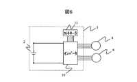
- FIG. 6 shows the configuration of a power supply system device for a general battery-type forklift that is conventionally known.
- the power supply system device 3 of the present example includes an inverter 10, a lead battery 2, and a controller 11 that gives a command to the inverter 10.
- the energy source of the battery-type forklift is only the lead battery 2, and the DC power of the lead battery 2 is converted into AC power by the inverter 10 to drive the electric motor 4 for traveling and the electric motor 6 for cargo handling.
- the inverter 10 constituting the power supply system device 3 has two power converters in order to drive the two motors 4 and 6 independently.
- the controller 11 outputs power according to the power required by the driver from the motors 4 and 6 (the operation amount determined by the accelerator, the brake pedal, and the cargo handling lever, although not particularly shown).
- the motors 4 and 6 are controlled via the inverter 10.
- the battery-type forklift frequently repeats acceleration / deceleration during traveling operation, and an electric brake is applied by the traveling electric motor 4 during braking. Therefore, a considerable amount of regenerative power is generated during traveling operation.
- the hydraulic oil in the hydraulic cylinder is released and the potential energy stored in the lift is discarded. If it is set as the structure which rotates a generator using, it is also possible to collect
- a battery-type forklift can generate a considerable amount of regenerative power from its operation.
- lead batteries used in battery-powered forklifts are not excellent in charging characteristics with short-time high currents such as regenerative power of electric motors, so apply regenerative power of electric motors directly to lead batteries. However, most of them are lost, and regenerative power cannot be used effectively. Therefore, recently, in order to compensate for the low rapid charging characteristics of the lead battery, a technique for improving the recovery amount of regenerative electric power from an electric motor or a lift by using a large-capacity capacitor has been proposed.
- Non-Patent Document 1 There have been several examples of technology that uses large capacity capacitors in combination with lead batteries. Among them, in a system device in which a large-capacity capacitor is connected in parallel to a battery via a DCDC converter, a current command is calculated so that the internal resistance of the capacitor can be regarded as zero, and control is performed so that the current flows through the capacitor. In particular, it is attracting attention as a technique for efficiently recovering regenerative power (see Non-Patent Document 1).
- Non-Patent Document 1 uses a differential operation on the battery voltage as a method for calculating the current command flowing through the capacitor during regeneration, it is required to include a controller having high calculation performance.
- Non-Patent Document 1 does not disclose a control method during power discharge, and it cannot be said that efficient driving is possible even during discharge, so there is room for improvement in this respect.
- the present invention has been made in view of the current state of the prior art, and an object of the present invention is to make the drive unit highly efficient both during regeneration (charging) and during power running (discharging) by a simple calculation method.
- An object of the present invention is to provide an electric industrial vehicle equipped with a drivable power supply system device.
- the present invention is an electric industrial vehicle including an electric motor that drives a drive unit of a vehicle, and a power supply system device that supplies motor drive power to the electric motor, the power supply system device A first power storage means that is inferior in charging characteristics at a short time and a large current, a second power storage means that is excellent in charging characteristics at a short time and a large current, a DCDC converter that performs voltage control of the second power storage means,
- the controller is configured to operate the first power storage means and the first power during a power running operation of the electric motor. 2 Based on each internal resistance of the power storage means and the load demand power of the electric motor, the first power storage means and the second power storage means And the configuration of determining the flow distribution.
- the first power storage unit is configured so that the loss of the power supply system device is minimized based on the internal resistances of the first and second power storage units and the required load power of the electric motor during the power running operation of the electric motor. Since the current distribution of the second power storage means is determined, the power supply system apparatus can be used with high efficiency. Therefore, by combining with a technique for improving the amount of recovered regenerative power by the second power storage means during regeneration, it is possible to increase the drive efficiency of the drive unit during both regeneration and power running. Further, since the current distribution of the first power storage means and the second power storage means is determined based on the internal resistances of the first and second power storage means and the load demand power of the electric motor, the first power storage means is performed without performing a differential operation. And the current distribution of the second power storage means can be determined, and the burden on the controller can be reduced.
- the controller controls the DCDC converter so that the regenerative power from the electric motor flows only in the second power storage unit during the regenerative operation of the electric motor. It was configured as follows.
- the second power storage means is excellent in charging characteristics with a large current for a short time, by adopting such a configuration, it is possible to efficiently recover regenerative power.
- the controller sets a current command value to be supplied to the first power storage unit during the regenerative operation of the electric motor to zero, and sets the current command value and the first power storage unit to
- the DCDC converter is configured to be feedback-controlled so that the deviation from the flowing current value becomes zero.
- the DCDC converter can be feedback controlled simply by adding or subtracting the current value flowing through the first power storage unit with respect to the current command value flowing through the first power storage unit, so that the burden on the controller can be reduced.
- the first power storage unit is a lead battery
- the second power storage unit is a large capacity capacitor
- a battery-type forklift 1 includes a driving wheel (tire) 5 driven by an electric motor 4 for traveling, a pump 7 driven by an electric motor 6 for cargo handling, and a pump 7.
- a hydraulic cylinder 8 driven by the discharged pressure oil and a lift 9 that rises or falls according to the expansion and contraction of the hydraulic cylinder 8 are provided.
- the battery-type forklift 1 is provided with a lead battery 2 as an energy source for the electric motor 4 for traveling and the electric motor 6 for cargo handling, and the electric power stored in the lead battery 2 is traveled by the power supply system device 3.
- the electric motor 4 and the cargo handling electric motor 6 are distributed in accordance with their respective required powers.
- the battery-type forklift 1 can travel by rotating the drive wheels 5 with the electric motor 4 for traveling, and the pump 7 is rotationally driven with the electric motor 6 for cargo handling and discharged from the pump 7.
- the flow of the pressurized oil is switched by a direction switching valve (not shown) or the like, and the hydraulic cylinder 8 can be extended or contracted to raise or lower the load.
- the power supply system device 3 includes a lead battery 2 and a large capacity capacitor 13 connected in parallel to the inverter 10, and a DCDC converter 12 that adjusts a voltage value applied to the large capacity capacitor 13.
- the current sensor 14 detects the current flowing through the lead battery 2 and the controller 11 controls the DCDC converter 12 according to the current flowing through the current sensor 14 and gives a command to the inverter 10.
- the power supply system apparatus collects the power only in the large capacity capacitor 13 without flowing the regenerative power through the lead battery 2.
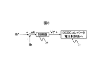
- the controller 11 detects the current Ib flowing through the lead battery 2 by the current sensor 14, feeds it back to the control system of the DCDC converter 12, and performs regenerative power regenerative control. That is, when the controller 11 determines that the current operation is “regenerative operation”, the current command Ib * to be passed through the lead battery 2 is set to zero, and the detection value Ib of the current sensor 14 is fed back to the current command Ib * .
- the controller 20 performs a control operation such as proportional integration so that the deviation ⁇ Ib between the current command Ib * and the detected value Ib becomes zero, and calculates the target voltage VC * of the large-capacitance capacitor 13. Further, the target voltage VC * of the large-capacity capacitor 13 is input to the DCDC converter voltage control system 21, and the voltage control of the large-capacity capacitor 13 by the DCDC converter 12 is performed.
- the above is an example of the control operation of the power supply system apparatus 3 using the large-capacitance capacitor 13 in the regeneration mode.
- the control operation of the power supply system apparatus 3 using the large-capacitance capacitor 13 in the regeneration mode is controlled by controlling the voltage of the large-capacity capacitor 13 using the DCDC converter 12 so that the current flowing through the lead battery 2 becomes zero, in the regeneration mode of the electric motor 4 for traveling and the electric motor 6 for cargo handling, All the regenerative power can be collected on the large-capacity capacitor 13 side.
- the lead battery 2 having low regenerative power acceptance characteristics is used as the energy source of the traveling electric motor 4 and the cargo handling electric motor 6, the regenerative power can be recovered with high efficiency.
- the electric motor 6 and the inverter 10 request the controller 11 for electric power necessary for the operation (work) at that time.
- the controller 11 takes out power from the lead battery 2 and the large-capacity capacitor 13 in accordance with the required power. At that time, also in the power running operation, it is necessary to control the power supply system device 3 with high efficiency as in the above-described regenerative operation.
- the lead battery 2 has a discharge characteristic equivalent to that of the large-capacitance capacitor 13, and thus, the lead battery 2 and the large-capacitance capacitor 13 are used together to drive the electric motor 4 for traveling and the electric motor 6 for cargo handling.
- the required power from the inverter 10 is covered. At this time, it is naturally preferable to distribute the power between the lead battery 2 and the large-capacitance capacitor 13 so that the loss during discharging is minimized.
- the controller 11 estimates the internal resistance of each of the lead battery 2 and the large-capacitance capacitor 13, and satisfies the required power of the electric motor 4 for traveling, the electric motor 6 for cargo handling, and the inverter 10, The burden electric power of the large capacity capacitor 13 is determined.
- FIG. 4 shows the configuration of the current distribution unit 30 that calculates the power distribution between the lead battery 2 and the large-capacitance capacitor 13 during the power running operation.
- the current distribution unit 30 of this example includes a required power calculation unit 25, an internal resistance calculation unit 26, and a power distribution unit 27.
- the current distribution unit 30 is provided in the controller 11.
- the required power calculation unit 25 inputs the rotation speed and temperature of the electric motor 4 for traveling and the electric motor 6 for cargo handling, the torque command value output from an unillustrated accelerator pedal, lift lift lever, etc., and the temperature of the inverter 10, Calculate the power required from time to time.
- a more specific configuration of the required power calculation unit 25 is shown in FIG. As is apparent from this figure, the required power calculation unit 25 of this example calculates the output for each of the traveling electric motor 4 and the cargo handling electric motor 6 based on the multiplication of the motor rotational speed and the torque command value.
- the loss at each motor operating point is calculated by the loss calculators 31 and 32 from the motor temperature and the temperature of the inverter 10, and the motors 4, 6 are calculated. Total output and loss are calculated to obtain the total required power.
- the internal resistance calculation unit 26 inputs the temperatures of the lead battery 2 and the large capacity capacitor 13 and calculates the internal resistance value for each power storage device.
- the internal resistance value calculation unit 26 stores internal resistance characteristics with respect to temperature for each of the power storage devices 2 and 13, and the internal resistance value is calculated based on the stored characteristics.
- the lead battery 2 and the large-capacitance capacitor 13 are connected using the total required power obtained by the required power calculation unit 25 and the internal resistance value obtained by the internal resistance calculation unit 26. Determine power distribution.
- the loss of the power supply system apparatus 3 is minimized.
- a loss W loss that occurs when a current is passed through a resistor is expressed by Equation 1 where I is the current and R is the resistance.
- Equation 1 the loss W loss is proportional to the square of the current I and the resistance value R, respectively. Therefore, in order to minimize the loss W loss , the power share of the power storage device having the smallest resistance R is increased.
- the capacity of the large-capacity capacitor 13 is on the order of 1/100 of a lead battery, and the power that can be used is limited. Therefore, the condition for enabling power distribution that can minimize loss is when the large-capacitance capacitor 13 stores enough power to cover it, and when the power stored in the large-capacity capacitor 13 decreases. Is the power distribution that minimizes the loss as much as possible in the remaining power range.
- the DCDC converter 12 is controlled based on the control block of FIG. 3 as in the above-described regenerative operation. That is, the current Ib flowing through the lead battery 2 is detected by the current sensor 14 and fed back to the control system of the DCDC converter 12.
- the current command Ib * for the lead battery is determined based on the power distribution amount of the lead battery 2 calculated by the power distribution unit 27. For example, a value obtained by dividing the power distribution amount of the lead battery 2 by the voltage value of the lead battery 2 may be used for the current command Ib *.
- a value obtained by dividing the power distribution amount of the lead battery 2 by the voltage value of the lead battery 2 may be used for the current command Ib *.
- the electric industrial vehicle of this example is configured such that the internal resistance of the lead battery 2 and the large-capacitance capacitor 13 and the required load power of the electric motors 2 and 4 during the power running operation of the traveling electric motor 4 and the cargo handling electric motor 6. Therefore, the current distribution of the lead battery 2 and the large-capacity capacitor 13 is determined so that the loss of the power supply system device 3 is minimized, so that the power supply system device 3 can be used with high efficiency. Therefore, by combining with a technique for improving the amount of recovered regenerative power by the second power storage means during regeneration, it is possible to increase the drive efficiency of the drive unit during both regeneration and power running. In addition, since the current distribution of the lead battery 2 and the large-capacitance capacitor 13 can be determined without performing a differentiation operation, the burden on the controller can be reduced.
- the DCDC converter 12 a step-up converter or a step-up / step-down converter can be used.
- the step-up converter when the voltage of the large-capacitance capacitor 13 becomes equal to or lower than the voltage of the lead battery 2, the upper arm element of the DCDC converter 12 is switched ON, and the electric motors 4, 6 Is switched to the lead battery 2.
- the DCDC converter 12 when a step-up / step-down converter is used as the DCDC converter 12, the DCDC converter 12 is operated so that the large-capacitance capacitor 13 operates within a predetermined voltage range when the electric motors 4 and 6 are powered. To control.
- the power supply system device 3 using the lead battery 2 and the large-capacitance capacitor 13 in combination has been described as an example.
- the combination of the two power storage devices provided in the power supply system device 3 is not limited to this.
- a combination of the first power storage unit that is inferior in charging characteristics at a short time and a large current and the second power storage unit that is excellent in charging characteristics at a short time and a large current is sufficient.
- the present invention can be used for an electric industrial vehicle such as a battery-type forklift.
Landscapes
- Engineering & Computer Science (AREA)
- Electrochemistry (AREA)
- General Chemical & Material Sciences (AREA)
- Chemical & Material Sciences (AREA)
- Chemical Kinetics & Catalysis (AREA)
- Power Engineering (AREA)
- Transportation (AREA)
- Mechanical Engineering (AREA)
- Manufacturing & Machinery (AREA)
- Life Sciences & Earth Sciences (AREA)
- Sustainable Energy (AREA)
- Sustainable Development (AREA)
- Electric Propulsion And Braking For Vehicles (AREA)
- Forklifts And Lifting Vehicles (AREA)
- Charge And Discharge Circuits For Batteries Or The Like (AREA)
- Secondary Cells (AREA)
Abstract
【課題】簡便な演算方法により、回生時及び力行時の双方において駆動部を高効率に駆動可能な電源システム装置を備えた電動産業車両を提供する。 【解決手段】電動産業車両の電源システム装置3を、鉛バッテリ2と、大容量キャパシタ13と、大容量キャパシタ13の電圧制御を行うDCDCコンバータ12と、鉛バッテリ2及び大容量キャパシタ13の充放電電力を制御するコントローラ11とから構成する。コントローラ11は、電動産業車両の駆動源である電動モータ4,6の力行動作時に、鉛バッテリ2及び大容量キャパシタ13の内部抵抗と、電動モータ4,6の負荷要求電力に基づいて、電源システム装置3の損失が最小となるように、鉛バッテリ2及び大容量キャパシタ13の電流配分を決定する。
Description
本発明は、バッテリ式フォークリフト等の電動産業車両に係り、特に、車両各部の駆動源に電源を供給する電源システム装置に関する。
近年、環境問題や原油高騰の問題などに対処するため、各工業製品に対して省エネ志向が強まっている。これを受けて、これまでエンジンによる油圧駆動システム装置が中心であった建設や荷役などの各種産業分野で使用される産業車両についても、電動化による高効率化、省エネルギ化の事例が増加してきている。産業車両を電動化した場合、すなわち産業車両の動力源として電動モータを用いた場合、排気ガスの低減のほか、エンジンの高効率駆動(ハイブリッドの場合)、伝達効率の向上、回生電力の回収などの省エネルギ効果が期待できる。
産業車両の中では、倉庫内や工場内で使用されることが多く、排ガスを出さないことが要求されるフォークリフトの電動化がいち早く進んでおり、バッテリの電力を用いて電動モータを駆動する「バッテリ式フォークリフト」が他の産業車両に先駆けて実用化されている。現在既に製品化されているバッテリ式フォークリフトは、電力源に鉛バッテリを使用し、この鉛バッテリの電力を用いて、直接走行用タイヤを電動モータで駆動し、走行を行う。また、荷物の昇降作業を行う荷役装置部分(リフト)においては、電動油圧システム装置が採用されており、専用の荷役モータで油圧ポンプを駆動し、発生した油圧でマスト部に設置された左右の油圧シリンダを作動させる構成となっている。
図6に、従来知られている一般的なバッテリ式フォークリフトの電源システム装置の構成を示す。この図に示すように、本例の電源システム装置3はインバータ10、鉛バッテリ2、ならびにインバータ10に指令を与えるコントローラ11で構成される。バッテリ式フォークリフトのエネルギ源は鉛バッテリ2のみであり、この鉛バッテリ2の直流電力をインバータ10にて交流電力に変換して、負荷となる走行用電動モータ4及び荷役用電動モータ6を駆動する。電源システム装置3を構成するインバータ10は、2つのモータ4,6をそれぞれ独立して駆動するため、2つの電力変換器を有している。コントローラ11は、各モータ4,6から運転者の要求するパワー(特に図示していないが、アクセルやブレーキペダル、ならびに荷役用レバーにより決定される操作量)通りに動力が出力されるように、インバータ10を介して各モータ4,6を制御する。
バッテリ式フォークリフトは、走行動作時に加減速を頻繁に繰り返しており、制動時には走行用電動モータ4により電気ブレーキがかけられるので、走行動作時において、かなりの量の回生電力を発生している。また、現状では、リフトを用いて持ち上げられた荷物を下降する際、油圧シリンダ内の圧油をリリースして、リフトに蓄えられた位置エネルギを廃棄してしまっているが、このリフトの位置エネルギを利用して発電機を回す構成とすれば、回生電力としてエネルギを回収することも可能である。このように、バッテリ式フォークリフトでは、その動作内容からかなりの量の回生電力が発生できることがわかる。
しかしながら、バッテリ式フォークリフトに使用されている鉛バッテリは、電動モータの回生電力等の短時間大電流での充電特性には優れていないので、電動モータの回生電力等を直接鉛バッテリに印加しても、ほとんどが損失になってしまい、回生電力等を有効利用することができない。そこで、最近では、鉛バッテリの低急速充電特性を補うために、大容量のキャパシタなどを併用して、電動モータやリフトからの回生電力の回収量を改善する技術が提案されている。
鉛バッテリに大容量のキャパシタを併用する技術は、これまでいくつかの事例が報告されている。その中でも、バッテリに対しDCDCコンバータを介して大容量キャパシタを並列接続したシステム装置において、キャパシタの内部抵抗をゼロとみなせるような電流指令を演算し、その電流がキャパシタに流れるように制御するものが、効率よく回生電力を回収する技術として特に注目される(非特許文献1参照。)。
平成20年電気学会全国大会 No.4-144、「バッテリに並列接続したEDLCの制御方法」、著者:明電舎 宮本ほか
しかしながら、非特許文献1に記載の技術は、回生を行う際のキャパシタに流れる電流指令の演算方法として、バッテリ電圧に対する微分演算を用いているので、高い演算性能を有するコントローラを備えることが要求される。また、非特許文献1には、電力放電時の制御方法が開示されておらず、放電時にも効率のよい駆動が可能になるとはいえないので、この点に改良の余地がある。
本発明は、このような従来技術の現状に鑑みてなされたものであり、その目的は、簡便な演算方法により、回生(充電)時及び力行(放電)時の双方において駆動部を高効率に駆動可能な電源システム装置を備えた電動産業車両を提供することにある。
本発明は、前記課題を解決するため、車両の駆動部を駆動する電動モータと、該電動モータにモータ駆動電力を供給する電源システム装置とを備えた電動産業車両であって、前記電源システム装置が、短時間大電流での充電特性に劣る第1蓄電手段と、短時間大電流での充電特性に優れた第2蓄電手段と、該第2蓄電手段の電圧制御を行うDCDCコンバータと、前記第1蓄電手段及び前記第2蓄電手段の充放電電力を制御するコントローラとを備えたものからなる電動産業車両において、前記コントローラは、前記電動モータの力行動作時に、前記第1蓄電手段及び前記第2蓄電手段の各内部抵抗と前記電動モータの負荷要求電力に基づいて、前記電源システム装置の損失が最小となるように、前記第1蓄電手段及び前記第2蓄電手段の電流配分を決定するという構成にした。
かかる構成によると、電動モータの力行動作時に、第1及び第2の蓄電手段の内部抵抗と電動モータの負荷要求電力に基づいて、電源システム装置の損失が最小となるように、第1蓄電手段及び第2蓄電手段の電流配分を決定するので、電源システム装置の高効率な利用が可能になる。よって、回生時における第2蓄電手段による回生電力の回収量を改善する技術と組合わせることにより、回生時と力行時、双方における駆動部の駆動を高効率化することができる。また、第1及び第2の蓄電手段の内部抵抗と電動モータの負荷要求電力に基づいて第1蓄電手段及び第2蓄電手段の電流配分を決定するので、微分演算を行うことなく第1蓄電手段及び第2蓄電手段の電流配分を決定することができ、コントローラの負担を軽減することができる。
また本発明は、前記構成の電動産業車両において、前記コントローラは、前記電動モータの回生動作時に、前記第2蓄電手段にのみ前記電動モータからの回生電力が流れるように、前記DCDCコンバータを制御するという構成にした。
第2蓄電手段は、短時間大電流での充電特性に優れているので、かかる構成とすることにより、回生電力を効率良く回収することができる。
また本発明は、前記構成の電動産業車両において、前記コントローラは、前記電動モータの回生動作時に、前記第1蓄電手段に流す電流指令値をゼロとし、この電流指令値と前記第1蓄電手段に流れる電流値との偏差がゼロになるように、前記DCDCコンバータをフィードバック制御するという構成にした。
かかる構成によると、第1蓄電手段に流す電流指令値に対して第1蓄電手段に流れる電流値を加減算するだけでDCDCコンバータをフィードバック制御できるので、コントローラの負担を軽減することができる。
また本発明は、前記構成の電動産業車両において、前記第1蓄電手段が鉛バッテリであり、前記第2蓄電手段が大容量キャパシタであるという構成にした。
鉛バッテリ及び大容量キャパシタを用いた電動産業車両は、技術的に確立しているので、かかる構成とすることにより、信頼性に優れた電動産業車両を実現できる。
本発明によれば、簡便な演算方法により、回生動作時及び力行動作時の双方において高効率駆動が可能な電源システム装置を備えた電動産業車両を提供することができる。
以下、本発明に係る電動産業車両の実施形態を、バッテリ式フォークリフトを例にとり説明する。
図1に示すように、実施形態に係るバッテリ式フォークリフト1は、走行用電動モータ4により駆動される駆動輪(タイヤ)5と、荷役用電動モータ6により駆動されるポンプ7と、ポンプ7から吐出される圧油にて駆動される油圧シリンダ8と、油圧シリンダ8の伸縮に応じて上昇又は下降するリフト9とを備えている。また、このバッテリ式フォークリフト1には、走行用電動モータ4及び荷役用電動モータ6のエネルギ源として鉛バッテリ2を備えており、鉛バッテリ2に蓄えられた電力は、電源システム装置3により、走行用電動モータ4及び荷役用電動モータ6に対して、それらの各要求パワーに応じた配分で配給される。したがって、実施形態に係るバッテリ式フォークリフト1は、走行用電動モータ4で駆動輪5を回転駆動することによって走行することができ、荷役用電動モータ6でポンプ7を回転駆動し、ポンプ7から吐出される圧油の流れを図示しない方向切換弁などで切り換えて、油圧シリンダ8を伸長又は収縮することによって荷物の上げ下ろしをすることができる。
電源システム装置3は、図2に示すように、インバータ10に対して並列に接続された鉛バッテリ2及び大容量キャパシタ13と、大容量キャパシタ13に印加される電圧値を調整するDCDCコンバータ12と、鉛バッテリ2に流れる電流を検出するカレントセンサ14と、カレントセンサ14に流れる電流に応じてDCDCコンバータ12を制御すると共に、インバータ10に指令を与えるコントローラ11とから構成されている。
この電源システム装置は、回生電力が発生した場合に、鉛バッテリ2にはその回生電力を流さず、大容量キャパシタ13にのみ電力を回収する。その際、コントローラ11は、図3に示すように、鉛バッテリ2に流れる電流Ibをカレントセンサ14により検出し、DCDCコンバータ12の制御系にフィードバックさせて、回生電力の回生制御を行う。即ち、コントローラ11が現在「回生動作」であると判断した場合には、鉛バッテリ2に流す電流指令Ib*をゼロとして、カレントセンサ14の検出値Ibを電流指令Ib*にフィードバックする。そして、この電流指令Ib*と検出値Ibとの偏差ΔIbがゼロとなるように制御器20で比例積分などの制御演算を行い、大容量キャパシタ13の目標電圧VC*を算出する。さらに、大容量キャパシタ13の目標電圧VC*をDCDCコンバータ電圧制御系21に入力して、DCDCコンバータ12による大容量キャパシタ13の電圧制御を行う。
以上が、回生モードにおける、大容量キャパシタ13を併用した電源システム装置3の制御動作例である。このように、鉛バッテリ2に流れる電流がゼロとなるようにDCDCコンバータ12を用いて大容量キャパシタ13の電圧を制御することにより、走行用電動モータ4及び荷役用電動モータ6の回生モードにおいて、回生電力をすべて大容量キャパシタ13側に回収することが可能となる。これにより、走行用電動モータ4及び荷役用電動モータ6のエネルギ源として、回生電力の受け入れ特性が低い鉛バッテリ2を用いる場合にも、高効率に回生電力の回収が可能となる。
一方、走行用電動モータ4からトルクを発生させて、バッテリ式フォークリフト1を走行したり、荷役用電動モータ6からトルクを発生させてリフト9を昇降する力行動作時には、走行用電動モータ4、荷役用電動モータ6及びインバータ10が、そのときの動作(作業)に必要な電力をコントローラ11に要求する。コントローラ11は、この要求電力に応じて鉛バッテリ2及び大容量キャパシタ13より電力を取りだす。その際、力行動作においても、前述の回生動作と同様に、高効率で電源システム装置3を制御することが必要である。前述の回生動作では、鉛バッテリ2の回生電力受け入れ特性が低いために、発生する回生電力のすべてを大容量キャパシタ13で回収するように制御した。これに対して、力行動作では、鉛バッテリ2は大容量キャパシタ13と同等の放電特性を有するため、鉛バッテリ2と大容量キャパシタ13を併用して、走行用電動モータ4、荷役用電動モータ6及びインバータ10からの要求パワーを賄うようにする。このとき、鉛バッテリ2と大容量キャパシタ13の電力分配は、当然ながら放電時の損失が最小となるように分配することが好ましい。そこで、コントローラ11は、鉛バッテリ2と大容量キャパシタ13の各々の内部抵抗を推定し、走行用電動モータ4、荷役用電動モータ6及びインバータ10の要求パワーを満足するように、鉛バッテリ2と大容量キャパシタ13の負担電力を決定する。
図4に、力行動作時における鉛バッテリ2と大容量キャパシタ13の電力分配を演算する電流分配部30の構成を示す。この図から明らかなように、本例の電流分配部30は、要求電力演算部25と、内部抵抗演算部26と、電力分配部27とからなる。なお、この電流分配部30は、コントローラ11内に設けられる。
要求電力演算部25は、走行用電動モータ4及び荷役用電動モータ6の回転数及び温度、図示しないアクセルペダルやリフト昇降レバー等から出力されるトルク指令値、並びにインバータ10の温度を入力し、その時々で必要な電力を演算する。この要求電力演算部25のより具体的な構成を図5に示す。この図から明らかなように、本例の要求電力演算部25は、走行用電動モータ4及び荷役用電動モータ6のそれぞれについて、モータ回転数とトルク指令値の乗算に基づいて出力を演算すると共に、走行用電動モータ4及び荷役用電動モータ6のそれぞれについて、そのモータ温度とインバータ10の温度とから損失演算部31,32にて各モータ動作点での損失を演算し、各モータ4,6の出力と損失を合計して、全要求電力を求める。
内部抵抗演算部26は、図4に示すように、鉛バッテリ2及び大容量キャパシタ13の温度を入力して、各蓄電装置についての内部抵抗値を算出する。内部抵抗値演算部26には、各蓄電装置2,13に関し、温度に対する内部抵抗特性が記憶されており、この記憶された特性に基づいて内部抵抗値が算出される。
図4の電力配分部27では、要求電力演算部25にて求められた全要求電力と、内部抵抗演算部26にて求められた内部抵抗値を用いて、鉛バッテリ2と大容量キャパシタ13の電力分配を決定する。このときの電力配分方法としては、電源システム装置3の損失が最小になるようにすることが好ましい。一般に、抵抗体に電流を流した際に発生する損失Wlossは、電流をI、抵抗をRとすると、数1で表される。
Wloss=I2×R ・・・(数1)
数1から明らかなように、損失Wlossは、電流Iの2乗及び抵抗値Rのそれぞれに比例する。よって損失Wlossを最小にするためには、できるだけ抵抗Rが小さい蓄電装置の電力分担分を増やすようにする。
数1から明らかなように、損失Wlossは、電流Iの2乗及び抵抗値Rのそれぞれに比例する。よって損失Wlossを最小にするためには、できるだけ抵抗Rが小さい蓄電装置の電力分担分を増やすようにする。
但し、大容量キャパシタ13の容量は、鉛バッテリの1/100程度のオーダであり、使用できる電力は限りがある。よって、損失を最小にできる電力配分が可能な条件は、それを賄える程度の電力を大容量キャパシタ13が蓄えているときであり、大容量キャパシタ13に蓄えられている電力が減少してきた場合には、残された電力の範囲で可能な限り損失を最小にする電力配分とする。電力配分決定後は、前述の回生動作時と同様に、図3の制御ブロックに基づいてDCDCコンバータ12の制御を行う。即ち、鉛バッテリ2に流れる電流Ibをカレントセンサ14により検出し、DCDCコンバータ12の制御系にフィードバックさせる。このとき、鉛バッテリの電流指令Ib*は、電力配分部27にて算出された鉛バッテリ2の電力配分量に基づいて決定される。例えば、鉛バッテリ2の電力配分量を鉛バッテリ2の電圧値で除した値を電流指令Ib*に用いればよい。以上のように、配分された2つの電力のうち、鉛バッテリ2に流れる電流のみを制御することにより、要求電力と鉛バッテリ2の電力の差分を、自動的に大容量キャパシタ13から負担することができるようになる。
このように、本例の電動産業車両は、走行用電動モータ4及び荷役用電動モータ6の力行動作時に、鉛バッテリ2及び大容量キャパシタ13の内部抵抗と各電動モータ2,4の負荷要求電力に基づいて、電源システム装置3の損失が最小となるように、鉛バッテリ2及び大容量キャパシタ13の電流配分を決定するので、電源システム装置3の高効率な利用が可能になる。よって、回生時における第2蓄電手段による回生電力の回収量を改善する技術と組合わせることにより、回生時と力行時、双方における駆動部の駆動を高効率化することができる。また、微分演算を行うことなく鉛バッテリ2及び大容量キャパシタ13の電流配分を決定できるので、コントローラの負担を軽減することができる。
なお、DCDCコンバータ12としては、昇圧型の変換器を用いることもできるし、昇降圧型の変換器を用いることもできる。昇圧型の変換器を用いた場合には、大容量キャパシタ13の電圧が鉛バッテリ2の電圧以下になったときに、DCDCコンバータ12の上側アーム素子をONに切り換えて、各電動モータ4,6への電力供給を鉛バッテリ2に切り換える。また、DCDCコンバータ12として、昇降圧型の変換器を用いた場合には、各電動モータ4,6の力行動作時において、大容量キャパシタ13が所定の電圧範囲内で動作するように、DCDCコンバータ12を制御する。
また、本実施例では鉛バッテリ2と大容量キャパシタ13を併用した電源システム装置3を例にとって説明したが、電源システム装置3に備えられる2つの蓄電装置の組合せは、これに限定されるものではなく、短時間大電流での充電特性に劣る第1蓄電手段と、短時間大電流での充電特性に優れた第2蓄電手段との組合せであれば足りる。
本発明は、バッテリ式フォークリフト等の電動産業車両に利用することができる。
1 バッテリ式フォークリフト
2 鉛バッテリ
3 電源システム装置
4 走行用電動モータ
6 荷役用電動モータ
9 リフト
10 インバータ
11 コントローラ
12 DCDCコンバータ
13 大容量キャパシタ
25 要求電力演算部
26 内部抵抗演算部
27 電力分配部
30 電流分配部
31,32 損失演算部
2 鉛バッテリ
3 電源システム装置
4 走行用電動モータ
6 荷役用電動モータ
9 リフト
10 インバータ
11 コントローラ
12 DCDCコンバータ
13 大容量キャパシタ
25 要求電力演算部
26 内部抵抗演算部
27 電力分配部
30 電流分配部
31,32 損失演算部
Claims (4)
- 車両の駆動部を駆動する電動モータと、該電動モータにモータ駆動電力を供給する電源システム装置とを備えた電動産業車両であって、前記電源システム装置が、短時間大電流での充電特性に劣る第1蓄電手段と、短時間大電流での充電特性に優れた第2蓄電手段と、該第2蓄電手段の電圧制御を行うDCDCコンバータと、前記第1蓄電手段及び前記第2蓄電手段の充放電電力を制御するコントローラとを備えたものからなる電動産業車両において、
前記コントローラは、前記電動モータの力行動作時に、前記第1蓄電手段及び前記第2蓄電手段の各内部抵抗と前記電動モータの負荷要求電力に基づいて、前記電源システム装置の損失が最小となるように、前記第1蓄電手段及び前記第2蓄電手段の電流配分を決定することを特徴とする電動産業車両。 - 前記コントローラは、前記電動モータの回生動作時に、前記第2蓄電手段にのみ前記電動モータからの回生電力が流れるように、前記DCDCコンバータを制御することを特徴とする請求項1に記載の電動産業車両。
- 前記コントローラは、前記電動モータの回生動作時に、前記第1蓄電手段に流す電流指令値をゼロとし、この電流指令値と前記第1蓄電手段に流れる電流値との偏差がゼロになるように、前記DCDCコンバータをフィードバック制御することを特徴とする請求項2に記載の電動産業車両。
- 前記第1蓄電手段が鉛バッテリであり、前記第2蓄電手段が大容量キャパシタであることを特徴とする請求項1乃至請求項3のいずれか1項に記載の電動産業車両。
Applications Claiming Priority (2)
| Application Number | Priority Date | Filing Date | Title |
|---|---|---|---|
| JP2009-195527 | 2009-08-26 | ||
| JP2009195527A JP2011050153A (ja) | 2009-08-26 | 2009-08-26 | 電動産業車両 |
Publications (1)
| Publication Number | Publication Date |
|---|---|
| WO2011024707A1 true WO2011024707A1 (ja) | 2011-03-03 |
Family
ID=43627813
Family Applications (1)
| Application Number | Title | Priority Date | Filing Date |
|---|---|---|---|
| PCT/JP2010/064012 Ceased WO2011024707A1 (ja) | 2009-08-26 | 2010-08-19 | 電動産業車両 |
Country Status (2)
| Country | Link |
|---|---|
| JP (1) | JP2011050153A (ja) |
| WO (1) | WO2011024707A1 (ja) |
Cited By (3)
| Publication number | Priority date | Publication date | Assignee | Title |
|---|---|---|---|---|
| CN102501760A (zh) * | 2011-11-09 | 2012-06-20 | 中国人民解放军军事交通学院 | 蓄电池叉车电动机驱动切换系统 |
| CN107323274A (zh) * | 2017-02-14 | 2017-11-07 | 宁波三星智能电气有限公司 | 一种基于物联网的充电桩系统及其控制方法 |
| CN110370982A (zh) * | 2018-04-13 | 2019-10-25 | 丰田自动车株式会社 | 电源控制装置 |
Families Citing this family (7)
| Publication number | Priority date | Publication date | Assignee | Title |
|---|---|---|---|---|
| US8897954B2 (en) * | 2011-05-05 | 2014-11-25 | Deere & Company | Method for calibrating position sensor on electric motor |
| FR2988926B1 (fr) * | 2012-03-28 | 2014-03-28 | Valeo Equip Electr Moteur | Procede et systeme d'alimentation electrique d'un vehicule automobile hybride a double stockeurs d'energie electrique |
| EP2994973B1 (en) * | 2013-05-08 | 2020-03-25 | Otis Elevator Company | Hybrid energy sourced battery or super-capacitor fed drive topologies |
| JP6141213B2 (ja) * | 2014-01-28 | 2017-06-07 | Kddi株式会社 | 電力供給システム及び電力供給制御装置 |
| JP7337482B2 (ja) * | 2018-03-22 | 2023-09-04 | 矢崎総業株式会社 | 電源装置 |
| JP7666021B2 (ja) * | 2021-03-01 | 2025-04-22 | 日産自動車株式会社 | バッテリ充放電制御システム及びバッテリ充放電制御方法 |
| JP2024092127A (ja) * | 2022-12-26 | 2024-07-08 | 株式会社小松製作所 | 作業機械 |
Citations (4)
| Publication number | Priority date | Publication date | Assignee | Title |
|---|---|---|---|---|
| JP2002325378A (ja) * | 2001-04-26 | 2002-11-08 | Kobelco Contstruction Machinery Ltd | ハイブリッド建設機械の動力制御装置 |
| JP2003219566A (ja) * | 2002-01-17 | 2003-07-31 | Komatsu Ltd | ハイブリッド電源システム |
| WO2009013891A1 (ja) * | 2007-07-25 | 2009-01-29 | Panasonic Corporation | 車両用電源装置 |
| JP2009044808A (ja) * | 2007-08-06 | 2009-02-26 | Honda Motor Co Ltd | 車両用電源装置 |
-
2009
- 2009-08-26 JP JP2009195527A patent/JP2011050153A/ja active Pending
-
2010
- 2010-08-19 WO PCT/JP2010/064012 patent/WO2011024707A1/ja not_active Ceased
Patent Citations (4)
| Publication number | Priority date | Publication date | Assignee | Title |
|---|---|---|---|---|
| JP2002325378A (ja) * | 2001-04-26 | 2002-11-08 | Kobelco Contstruction Machinery Ltd | ハイブリッド建設機械の動力制御装置 |
| JP2003219566A (ja) * | 2002-01-17 | 2003-07-31 | Komatsu Ltd | ハイブリッド電源システム |
| WO2009013891A1 (ja) * | 2007-07-25 | 2009-01-29 | Panasonic Corporation | 車両用電源装置 |
| JP2009044808A (ja) * | 2007-08-06 | 2009-02-26 | Honda Motor Co Ltd | 車両用電源装置 |
Cited By (4)
| Publication number | Priority date | Publication date | Assignee | Title |
|---|---|---|---|---|
| CN102501760A (zh) * | 2011-11-09 | 2012-06-20 | 中国人民解放军军事交通学院 | 蓄电池叉车电动机驱动切换系统 |
| CN107323274A (zh) * | 2017-02-14 | 2017-11-07 | 宁波三星智能电气有限公司 | 一种基于物联网的充电桩系统及其控制方法 |
| CN110370982A (zh) * | 2018-04-13 | 2019-10-25 | 丰田自动车株式会社 | 电源控制装置 |
| CN110370982B (zh) * | 2018-04-13 | 2022-08-05 | 丰田自动车株式会社 | 电源控制装置 |
Also Published As
| Publication number | Publication date |
|---|---|
| JP2011050153A (ja) | 2011-03-10 |
Similar Documents
| Publication | Publication Date | Title |
|---|---|---|
| JP2011050153A (ja) | 電動産業車両 | |
| JP5356543B2 (ja) | 作業用車両の駆動制御装置 | |
| JP6613233B2 (ja) | エネルギー効率のよい電気自動車制御システム | |
| CN101003259B (zh) | 车辆驱动系统 | |
| JP5340381B2 (ja) | 電源システムを備えた建設機械及び産業車両 | |
| CN1321017C (zh) | 驱动装置及装备该驱动装置的汽车 | |
| JP4444343B2 (ja) | 燃料電池車両 | |
| JP5097687B2 (ja) | 鉄道車両及び鉄道車両用駆動装置 | |
| CN110446639A (zh) | 作业车辆的电力再生系统 | |
| WO2013024869A1 (ja) | 作業車両 | |
| US10239530B2 (en) | Vehicle control apparatus for a regenerative braking system based on the battery input power | |
| WO2012050010A1 (ja) | 建設機械 | |
| JP7041095B2 (ja) | 電源システム | |
| JP2019122201A (ja) | 電動車両 | |
| CN103241619B (zh) | 一种节能电梯及其运行的控制方法 | |
| JP5704676B2 (ja) | ハイブリッド型作業機械 | |
| WO2014141955A1 (ja) | ハイブリッド式作業車両 | |
| CN103255801A (zh) | 一种混合动力机械的储能装置能量控制方法 | |
| JP2009062110A (ja) | フォークリフト及びフォークリフトにおけるキャパシタの充電制御方法 | |
| KR101237317B1 (ko) | 4륜구동 하이브리드 차량의 추진 장치 및 방법 | |
| JP2015163022A (ja) | 作業車両 | |
| JP4712895B2 (ja) | 燃料電池車両 | |
| JP2011190623A (ja) | ハイブリッド型作業機械 | |
| JP5726929B2 (ja) | 建設機械及び建設機械の制御方法 | |
| JP2011079637A (ja) | 電動産業車両 |
Legal Events
| Date | Code | Title | Description |
|---|---|---|---|
| 121 | Ep: the epo has been informed by wipo that ep was designated in this application |
Ref document number: 10811757 Country of ref document: EP Kind code of ref document: A1 |
|
| NENP | Non-entry into the national phase |
Ref country code: DE |
|
| 122 | Ep: pct application non-entry in european phase |
Ref document number: 10811757 Country of ref document: EP Kind code of ref document: A1 |