WO2011016156A1 - 温度センサ及びその製造方法 - Google Patents
温度センサ及びその製造方法 Download PDFInfo
- Publication number
- WO2011016156A1 WO2011016156A1 PCT/JP2010/001211 JP2010001211W WO2011016156A1 WO 2011016156 A1 WO2011016156 A1 WO 2011016156A1 JP 2010001211 W JP2010001211 W JP 2010001211W WO 2011016156 A1 WO2011016156 A1 WO 2011016156A1
- Authority
- WO
- WIPO (PCT)
- Prior art keywords
- holder member
- holder
- temperature sensor
- temperature
- detection element
- Prior art date
- Legal status (The legal status is an assumption and is not a legal conclusion. Google has not performed a legal analysis and makes no representation as to the accuracy of the status listed.)
- Ceased
Links
Images





Classifications
-
- B—PERFORMING OPERATIONS; TRANSPORTING
- B29—WORKING OF PLASTICS; WORKING OF SUBSTANCES IN A PLASTIC STATE IN GENERAL
- B29C—SHAPING OR JOINING OF PLASTICS; SHAPING OF MATERIAL IN A PLASTIC STATE, NOT OTHERWISE PROVIDED FOR; AFTER-TREATMENT OF THE SHAPED PRODUCTS, e.g. REPAIRING
- B29C45/00—Injection moulding, i.e. forcing the required volume of moulding material through a nozzle into a closed mould; Apparatus therefor
- B29C45/14—Injection moulding, i.e. forcing the required volume of moulding material through a nozzle into a closed mould; Apparatus therefor incorporating preformed parts or layers, e.g. injection moulding around inserts or for coating articles
- B29C45/14639—Injection moulding, i.e. forcing the required volume of moulding material through a nozzle into a closed mould; Apparatus therefor incorporating preformed parts or layers, e.g. injection moulding around inserts or for coating articles for obtaining an insulating effect, e.g. for electrical components
-
- G—PHYSICS
- G01—MEASURING; TESTING
- G01K—MEASURING TEMPERATURE; MEASURING QUANTITY OF HEAT; THERMALLY-SENSITIVE ELEMENTS NOT OTHERWISE PROVIDED FOR
- G01K7/00—Measuring temperature based on the use of electric or magnetic elements directly sensitive to heat ; Power supply therefor, e.g. using thermoelectric elements
- G01K7/16—Measuring temperature based on the use of electric or magnetic elements directly sensitive to heat ; Power supply therefor, e.g. using thermoelectric elements using resistive elements
- G01K7/22—Measuring temperature based on the use of electric or magnetic elements directly sensitive to heat ; Power supply therefor, e.g. using thermoelectric elements using resistive elements the element being a non-linear resistance, e.g. thermistor
-
- G—PHYSICS
- G01—MEASURING; TESTING
- G01K—MEASURING TEMPERATURE; MEASURING QUANTITY OF HEAT; THERMALLY-SENSITIVE ELEMENTS NOT OTHERWISE PROVIDED FOR
- G01K7/00—Measuring temperature based on the use of electric or magnetic elements directly sensitive to heat ; Power supply therefor, e.g. using thermoelectric elements
- G01K7/16—Measuring temperature based on the use of electric or magnetic elements directly sensitive to heat ; Power supply therefor, e.g. using thermoelectric elements using resistive elements
- G01K2007/163—Measuring temperature based on the use of electric or magnetic elements directly sensitive to heat ; Power supply therefor, e.g. using thermoelectric elements using resistive elements provided with specially adapted connectors
Definitions
- the present invention relates to a temperature sensor used for detecting the temperature of hydraulic oil of an automobile engine or an automatic transmission.
- a temperature sensor that is incorporated in an automobile engine, an automatic transmission, or the like and detects the temperature of hydraulic oil (hereinafter referred to as oil temperature) is used for the control thereof.
- This type of temperature sensor incorporates a temperature detection element such as a thermistor in the temperature sensing section, and a signal related to oil temperature information detected by the temperature detection element is sent to an external electronic control device (ECU, etc.) via a lead wire. To be sent to.
- ECU electronice control device
- a conventional temperature sensor has a structure in which a temperature detection element is molded in a synthetic resin by insert molding.
- an external conductor is connected and fixed in advance to the lead wire of the temperature detection element, and the temperature detection element is positioned by sandwiching the external conductor with a molding die.
- Patent Document 2 Japanese Patent Application Laid-Open No. 2005-19644 also discloses a technique in which a narrow portion is provided in the middle portion of the mold and the movement of the thermistor due to the resin injection pressure is restricted. It has not yet been a sufficient solution for any of the problems of preventing the displacement of the detection element and ensuring the connection reliability between the lead wire of the temperature detection element and the external conductor.
- the present invention has been made in the background of the above-described circumstances, and the problem to be solved is that the built-in temperature detection element can be accurately positioned, and the lead wire and the external conductor of the temperature detection element can be used. It is an object of the present invention to provide a temperature sensor having a novel structure in which the connection reliability of the device is improved and a method for manufacturing the same.
- a synthetic resin holder member including a conductive connecting member is used,
- the lead wire of the temperature detection element and the external conductor are connected to each other by being fixed to the connection member and positioned and fixed to the holder member, while the holder member and the outside of the temperature detection element
- the case is insert-molded.
- the case is insert-molded on the outer periphery of the holder member while the temperature detection element (lead wire) is positioned and held by the holder member.
- the temperature detection element is prevented from being displaced due to the pressure of the injected resin at the time of molding the case, and the desired detection accuracy is stably maintained.
- the case is insert-molded in a state where the lead wire of the temperature detection element and the external lead wire are both positioned and fixed by the connection member of the holder member (at the mutual connection portion). Accordingly, the connecting work between the lead wire and the external conducting wire can be easily performed while being positioned with respect to the holder member. In addition, even when the resin pressure during molding of the case is applied, the connecting part of the lead wire and the external conductor is fixedly supported, so that the connecting part is prevented from being deformed or displaced. Reliability is effectively ensured.
- a second aspect of the present invention is the one described in the first aspect, wherein the lead wire of the temperature detection element and the external conductor are caulked and fixed by the connecting member. is there.
- the lead wire and the external lead wire are caulked and fixed by the connecting member integrally provided on the holder member, thereby making it stronger and simpler (requiring other connecting materials, etc.) None) can be joined.
- a third aspect of the present invention is the element positioning according to the first or second aspect, wherein the temperature detection element is engaged with the holder member and relative displacement with respect to the holder member is restricted.
- the part is formed.
- the element positioning portion not only positioning at the connecting portion of the lead wire and the external conducting wire by the connecting member but also positioning of the temperature detecting element can be performed together.
- the positioning accuracy and reliability of the temperature detecting element with respect to the resin pressure during insert molding can be further improved.
- the tip according to any one of the first to third aspects, wherein the holder member has a tip from which the temperature detecting element is arranged from a base end portion from which the external conductor is taken out.
- the connection member is provided so as to extend in the longitudinal shape extending toward the portion, and projecting on both sides in the width direction of the intermediate portion in the longitudinal direction of the holder member, and the pair of the temperature detection elements Lead wires are arranged so as to extend along both side portions in the width direction of the holder member.
- the pair of lead wires is positioned in the width direction of the holder member. It can be positioned and disposed along both side portions. As a result, the pair of lead wires can be wired and positioned as far as possible from each other, and problems such as a short circuit can be avoided more effectively.
- the first step of obtaining the holder member provided with the connection member, and the temperature detection element The second step to be prepared, and the holder member obtained by the first step, the temperature detection element prepared in the second step is assembled, the lead wire, using the connection member, A third step of connecting to an external conductor and positioning and fixing to the holder member, and the holder member assembled with the temperature detecting element in the third step are accommodated in a mold, and the case is insert-molded And a fourth step.
- the target temperature sensor can be manufactured.
- the built-in temperature detection element can be accurately positioned, and the connection reliability between the lead wire of the temperature detection element and the external conductor can be improved.
- FIG. 2 is a partially cutaway cross-sectional view of the temperature sensor shown in FIG. 1. Sectional drawing of the III-III direction in FIG.
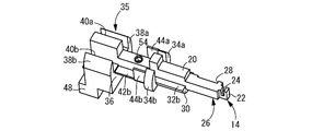
- the perspective view which shows the holder member which comprises the temperature sensor shown in FIG.
- the right view of the holder member shown in FIG. Sectional drawing of the VII-VII direction in FIG.
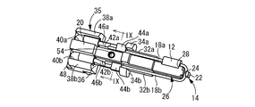
- the perspective view which shows the state by which the lead wire of the temperature detection terminal and the external conducting wire were positioned and fixed with respect to the holder member shown in FIG.
- the temperature sensor 10 includes a holder member 14 to which the temperature detection element 12 is assembled, and the temperature detection element 12 is built in the case 16 by covering the holder member 14 with the case 16.
- one end side in the longitudinal direction (right end side in FIG. 1) of the holder member 14 is referred to as a base end side
- the other end side in the longitudinal direction (left end side in FIG. 1) is referred to as a distal end side.
- the temperature detection element 12 is configured by a conventionally known glass-enclosed chip thermistor and includes a pair of lead wires 18a and 18b.
- the holder member 14 to which the temperature detecting element 12 is assembled is made of a non-conductive synthetic resin material and includes a holder body 20 as shown in FIGS.
- the holder body 20 has a rectangular block shape as a whole, and the dimension in the longitudinal direction (vertical direction in FIG. 5) is the dimension in the width direction (horizontal direction in FIG. 5) or thickness direction (vertical direction in FIG. 6). Has been made bigger than.
- a protrusion 22 that protrudes outward in the longitudinal direction of the holder body 20 is provided on the front end surface of the holder body 20.
- the protrusion 22 is formed with a locking groove 24 that opens to one side in the thickness direction (upper side in FIG. 6) and extends over the entire length in the width direction (left-right direction in FIG. 5).
- An element positioning portion 28 is formed on one side in the width direction of the tip portion 26 of the holder body 20.
- the element positioning portion 28 has a shallow groove shape formed so as to cut out one side in the width direction of the holder body 20 over the entire length in the thickness direction.
- the element positioning part 28 does not need to be a ditch
- a support portion 30 having a width dimension larger than that of the holder main body 20 is provided at an intermediate portion in the longitudinal direction of the holder main body 20 so as to be overlapped from the other side in the thickness direction (lower side in FIG. 6).
- support surfaces 32 a and 32 b are formed on the support portion 30 so as to extend outward in the width direction from both side surfaces of the holder body 20 in the width direction.
- regulation pieces 34 a and 34 b provided with opposing surfaces protruding from both side surfaces in the width direction and extending in parallel with the side surface of the holder main body 20 are provided.
- the holder main body 20 has a thickness dimension larger than that of the tip end portion 26 where the element positioning portion 28 is formed at the position where the restricting pieces 34a and 34b are formed.
- a support portion 36 having a width dimension larger than that of the holder body 20 is provided on the other side in the thickness direction of the base end portion 35 of the holder body 20 (the lower side in FIG. 6).
- Vertical walls 38 a and 38 b projecting toward one side in the thickness direction of the holder body 20 (upper side in FIG. 6) are provided at the edge portions in the width direction (left and right direction in FIG. 5) of the support part 36. It is provided over the full length of.
- the positioning grooves 40 a and 40 b are formed by the holder main body 20 and the vertical walls 38 a and 38 b so as to form a pair of side walls and extend parallel to the holder main body 20. Is formed.
- the bottom surfaces of the positioning grooves 40a and 40b are at the same height as the support surfaces 32a and 32b.
- the holder body 20 has a thickness dimension larger than that of the tip end portion 26 where the element positioning portion 28 is formed at the position where the positioning grooves 40a and 40b are formed.
- connection members 42a and 42b are integrally attached between the support portion 30 and the support portion 36.
- Each of the pair of connection members 42a and 42b is made of a conductive metal material and has a thin flat plate shape as a whole.
- connection members 42 a and 42 b are provided between the support portion 30 and the support portion 36 so as to protrude from the side surface in the width direction of the holder body 20.
- One end in the longitudinal direction of the connection members 42 a and 42 b is embedded in the support portion 30, and the other end in the longitudinal direction is embedded in the support portion 36.
- the holder body 20 has a thickness dimension larger than that of the tip end portion 26 where the element positioning portion 28 is formed at the projecting positions of the connection members 42a and 42b.
- the connection members 42a and 42b are on the other side (lower side in FIG. 6) of the holder body 20 in the thickness direction and at a position lower than the support surfaces 32a and 32b. Projects from the side in the width direction. Thereby, as will be described later, it is possible to effectively prevent a short circuit between the lead wires 18a and 18b disposed on both sides of the holder body 20 in the width direction.
- the caulking pieces 44a and 44b are provided at the projecting ends of the connecting members 42a and 42b from the holder body 20 near the support portion 30.
- the caulking pieces 44a and 44b have substantially constant width dimensions and project toward one side in the thickness direction of the holder body 20 (upper side in FIG. 6).
- the holder member 14 is assembled with the temperature detection element 12 and external conductors 46a and 46b connected to the lead wires 18a and 18b of the temperature detection element 12. It is done.
- the temperature detection element 12 is assembled to the holder member 14 in a state of being disposed on one side of the holder body 20 in the width direction. At that time, the temperature detecting element 12 is engaged with the element positioning portion 28. Thereby, relative displacement of the temperature detection element 12 in the longitudinal direction with respect to the holder member 14 is prevented.
- One lead wire 18a extends along one side surface in the width direction of the holder body 20, and is placed on the support surface 32a on one side in the width direction.
- the other lead wire 18b extends from the tip end side of the holder body 20 to the other side in the width direction, and then extends along the other side surface in the width direction of the holder body 20, and is mounted on the support surface 32b on the other side in the width direction. Is placed.
- the temperature detection element 12 is assembled to the holder member 14 so that the pair of lead wires 18a and 18b are positioned on both sides in the width direction with the holder body 20 interposed therebetween.
- the other lead wire 18b is fitted into the locking groove 24 and locked near the base end. Thereby, relative displacement of the temperature detection element 12 in the thickness direction with respect to the holder member 14 is prevented.
- the lead wires 18a and 18b pass between the holder main body 20 and the regulating pieces 34a and 34b. Thereby, the front-end
- the external conductors 46a and 46b connected to the lead wires 18a and 18b are assembled to the holder member 14 so as to be positioned in the positioning grooves 40a and 40b.
- tip part of the external conducting wires 46a and 46b is located on the connection members 42a and 42b.
- the caulking pieces 44a and 44b of the connecting members 42a and 42b are caulked, so that the leading end portions of the lead wires 18a and 18b and the leading end portions of the external conductors 46a and 46b are connected to the caulking pieces 44a and 44b. It is clamped between the members 42a and 42b.
- the lead wires 18a and 18b and the external conductors 46a and 46b are electrically connected in a state where they are positioned and fixed with respect to the holder member 14.
- the external conducting wires 46a and 46b are inserted into the insertion holes 50a and 50b (see FIG. 5) of the conducting wire holding portion 48 integrally formed with the support portion 36 in a state assembled to the holder member 14. Thereby, the external conductors 46a and 46b are taken out from the holder member 14 so as to extend from the lower side in the thickness direction on the base end side of the holder member 14 to the outside.
- the holder member 14 assembled with the temperature detecting element 12 and the external conductors 46a and 46b is substantially entirely made of a synthetic resin material except for a part of the conductor holding portion 48, as shown in FIGS.
- the case 16 is covered. Thereby, the temperature sensor 10 in which the temperature detecting element 12 is embedded in the case 16 is obtained.
- the first step is to set a pair of connection members 42a and 42b as inserts in a molding die (not shown), and then fill the molding die with a synthetic resin material that will form the holder member 14. Done.
- the holder member 14 in which the pair of connection members 42a and 42b is insert-molded is obtained.
- the temperature detection element 12 is performed by preparing separately what is obtained by enclosing a thermistor in a glass material by a known manufacturing method.
- the temperature detection element 12 is assembled to the holder member 14, and a third step of connecting the lead wires 18a and 18b of the temperature detection element 12 and the external conductors 46a and 46b is performed.
- the external conductors 46a and 46b are inserted into the insertion holes 50a and 50b formed in the conductor holding part 48 and then accommodated in the positioning grooves 40a and 40b, and the external conductors 46a and 46b are assembled to the holder member 14.
- the tip portions of the external conductors 46a and 46b are positioned on the connection members 42a and 42b.
- the temperature detecting element 12 is engaged with the element positioning portion 28, and the vicinity of the base end portion of the other lead wire 18b is engaged with the engaging groove 24.
- the lead wires 18a and 18b are placed on the support surfaces 32a and 32b, and are positioned between the holder body 20 and the restricting pieces 34a and 34b.
- the temperature detecting element 12 is assembled to the holder member 14, and the leading ends of the lead wires 18a and 18b are connected to the connecting member 42a. , 42b.
- the caulking pieces 44a and 44b are subjected to caulking processing so that the tip portions of the caulking pieces 44a and 44b are tilted toward the holder main body 20, so that the lead wires are connected between the caulking pieces 44a and 44b and the connecting members 42a and 42b.
- the tip portions of 18a and 18b and the tip portions of the external conductors 46a and 46b are clamped.
- the lead wires 18 a and 18 b and the external conductor wires 46 a and 46 b are electrically connected in a state where the lead wires 18 a and 18 b are positioned and fixed to the holder member 14.
- a fourth step of insert-molding the case 16 is performed using the holder member 14 to which the temperature detection element 12 and the external conductors 46a and 46b are assembled as an insert product.
- the holder member 14 to which the temperature detecting element 12 and the external conductors 46a and 46b are assembled is set as an insert in a mold.
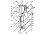
- a mold constituted by a fixed side mold 52 shown in FIG. 10 and a movable side mold (not shown) is used.
- the moving-side mold is moved toward the fixed-side mold 52 to form the mold.
- the forming material (synthetic resin material) of the case 16 is filled into the mold.
- the positioning of the holder member 14 in the mold is provided in each of the movable side mold and the fixed side mold 52 with respect to the positioning holes 54 and 54 opened in both end surfaces in the thickness direction of the holder body 20. This is done by fitting a positioning pin (not shown). Thereafter, the movable side mold is moved away from the fixed side mold 52 to open the mold, and the molded product is taken out from the mold with an unillustrated ejector pin, thereby obtaining the temperature sensor 10 shown in FIGS.
- the caulking pieces 44a and 44b of the connecting members 42a and 42b are caulked to hold the lead wires 18a and 18b of the temperature detecting element 12 and the external conductors 46a and 46b.
- Case 16 is insert-molded with 14 as an insert. Thereby, it is possible to avoid the problem that the position of the temperature detecting element 12 is shifted due to the pressure when the resin material is injected into the mold of the case 16. As a result, it is possible to obtain the temperature sensor 10 having the target detection accuracy.
- the temperature detection element 12 is assembled to the holder member 14 in a state where the temperature detection element 12 is engaged with the element positioning portion 28. As a result, it is possible to effectively prevent the temperature detecting element 12 from being displaced in the longitudinal direction of the holder member 14 due to the injection pressure of the resin material.
- the lead wire 18b of the temperature detecting element 12 is locked in the locking groove 24 in the vicinity of the base end portion. As a result, it is possible to effectively prevent the temperature detection element 12 from being displaced in the thickness direction of the holder member 14 due to the injection pressure of the resin material.
- the connecting portions of the lead wires 18a and 18b and the external conductors 46a and 46b are clamped between the caulking pieces 44a and 44b and the connecting members 42a and 42b, the lead wire 18a caused by the injection pressure of the resin material. , 18b and the external conductors 46a, 46b can be prevented from being deformed or displaced. As a result, the connection reliability between the lead wires 18a and 18b and the external conductors 46a and 46b can be ensured.
- the positioning and fixing of the lead wires 18a and 18b and the external conductors 46a and 46b with respect to the holder member 14 and electrical connection can be performed simultaneously. It has become. Thereby, the manufacturing process can be simplified.
- the embodiment only one connecting member may be employed. Even in such an embodiment, since the connection between the lead wire and the external conductor using the connecting member is achieved, the positioning of the lead wire and the external conductor can be stabilized, and the lead wire and Connection reliability of external conductors can be ensured.
- the lead wire not using the connecting member and the external conductor may be connected by using a separately provided crimp connection fitting in addition to the holder member. This can be realized by soldering at a position away from the connection member.
- connection between the lead wire and the external lead wire may be performed by soldering or ultrasonic welding the lead wire and the external lead wire on the connecting member.
- soldering, ultrasonic welding, etc. are employ
- the connecting member does not need to be insert-molded in the holder member, and may be fixed to the holder member by any fixing method such as bolt fixing.
Landscapes
- Physics & Mathematics (AREA)
- Engineering & Computer Science (AREA)
- Manufacturing & Machinery (AREA)
- Mechanical Engineering (AREA)
- Nonlinear Science (AREA)
- General Physics & Mathematics (AREA)
- Measuring Temperature Or Quantity Of Heat (AREA)
Abstract
内蔵される温度検出素子の位置決めを正確に行うことができると共に、温度検出素子のリード線と外部導線との接続信頼性が向上される新規な構造の温度センサおよびその製造方法を提供することを、目的とする。 導電性の接続部材42a,42bを備えた合成樹脂製のホルダー部材14を採用して、温度検出素子12のリード線18a,18bと外部導線46a,46bを、接続部材42a,42bに固着して相互に接続した状態で、ホルダー部材14に位置決め固定する一方、ホルダー部材14と温度検出素子12の外側にケース16をインサート成形した。
Description
本発明は、自動車のエンジンや自動変速機の作動油の温度等を検知するのに用いられる温度センサに関する。
従来から、自動車のエンジンや自動変速機等に組み込まれて、それらの制御のために作動油の温度(以下、油温という)を検出する温度センサが用いられている。この種の温度センサには、感温部にサーミスタ等の温度検出素子が内蔵されており、温度検出素子で検出した油温情報に関する信号がリード線を介して外部の電子制御装置(ECU等)に送信されるようになっている。
ところで、従来の温度センサは、特許第4041018号公報(特許文献1)に記載されているように、温度検出素子をインサート成形により合成樹脂中にモールドした構造とされている。また、このインサート成形に際しては、温度検出素子のリード線に予め外部導線を接続固定しておいて、この外部導線を成形型で挟持等することにより、温度検出素子が位置決めされている。
ところが、このような従来の温度センサでは、インサート成形に際して、成形キャビティ内に位置決めした温度検出素子が樹脂の注入圧力により位置ずれを起こすおそれがあった。特に、温度検出素子が感温部からずれてしまうと温度センサの所期の検出精度が得られず問題となる。また、樹脂の注入圧力により温度検出素子のリード線と外部導線との接続固定部分に過大な外力が加わり易いことから、充分な接続信頼性が得られ難いという問題もあった。
なお、特許文献2(特開2005-19644号公報)には、成形型の中間部分に幅狭部を設けて、樹脂の注入圧力によるサーミスタの移動を規制する技術も開示されているが、温度検出素子の位置ずれ防止および温度検出素子のリード線と外部導線との接続信頼性の確保の何れの問題に対しても、未だ充分な解決策とはなり得なかった。
本発明は、上述の事情を背景に為されたものであって、その解決課題は、内蔵される温度検出素子の位置決めを正確に行うことができると共に、温度検出素子のリード線と外部導線との接続信頼性が向上される新規な構造の温度センサおよびその製造方法を提供することにある。
本発明の第一の態様は、合成樹脂製のケースに温度検出素子が埋設状態で内蔵された温度センサにおいて、導電性の接続部材を備えた合成樹脂製のホルダー部材が用いられており、前記温度検出素子のリード線と外部導線とが前記接続部材に固着されることによって相互に接続されていると共に前記ホルダー部材に対して位置決め固定されている一方、前記ホルダー部材と前記温度検出素子の外側に前記ケースがインサート成形されていることを、特徴とする。
第一の態様によれば、ホルダー部材によって温度検出素子(リード線)が位置決め保持された状態で、ケースがホルダー部材の外周にインサート成形されている。これにより、ケース成形時の注入樹脂の圧力により、温度検出素子の位置ずれが防止されて、所期の検出精度が安定して維持される。
また、温度検出素子のリード線と外部導線が、何れも(相互の接続部において)ホルダー部材の接続部材によって位置決め固定された状態で、ケースがインサート成形される。従って、リード線と外部導線の接続作業を、ホルダー部材に対して位置決めされた状態で容易に行うことが可能となることから作業をし易い。また、ケースの成形時の樹脂圧力が作用した場合にも、リード線と外部導線の接続部は固定的に支持されていることから、当該接続部の変形や変位が防止されることとなり、接続信頼性が効果的に確保される。
本発明の第二の態様は、第一の態様に記載のものにおいて、前記温度検出素子のリード線と前記外部導線とが、前記接続部材によってかしめ固定されて接続されているようにしたものである。
第二の態様によれば、ホルダー部材に一体的に設けられた接続部材によってリード線と外部導線とをかしめ固定することにより、一層強固に且つ簡単に(他の接続材などを必要とすることなく)接合が可能となる。
本発明の第三の態様は、前記第一又は第二の態様に記載のものにおいて、前記ホルダー部材には、前記温度検出素子が係合して前記ホルダー部材に対する相対変位が規制される素子位置決め部が形成されているようにしたものである。
第三の態様によれば、素子位置決め部を採用することにより、接続部材によるリード線と外部導線の接続部分での位置決めだけでなく、温度検出素子の位置決めも併せて行うことができ、ケースのインサート成形時の樹脂圧力に対する温度検出素子の位置決め精度と信頼性の更なる向上が図られる。
本発明の第四の態様は、前記第一~第三の何れかの態様に記載のものにおいて、前記ホルダー部材が、前記外部導線が取り出される基端部分から前記温度検出素子が配される先端部分に向かって延びる長手形状とされていると共に、前記ホルダー部材の長手方向の中間部分における幅方向両側にそれぞれ突出して前記接続部材が設けられており、前記温度検出素子に設けられた一対の前記リード線が、前記ホルダー部材の幅方向両側部分に沿って延びるようにして配設されているようにしたものである。
第四の態様によれば、一対のリード線を、それぞれ、ホルダー部材の幅方向両側に突設した接合部材により外部導線と接続し且つ位置決めすることにより、一対のリード線をホルダー部材の幅方向両側部分に沿って位置決めして配設できる。これにより、一対のリード線を相互にできるだけ離して配線・位置決めすることができ、ショートなどの不具合を一層有効に回避可能と為し得る。
本発明の第五の態様は、第一~第四の何れかの態様に記載の温度センサを製造するに際して、前記接続部材を備えた前記ホルダー部材を得る第一工程と、前記温度検出素子を準備する第二工程と、前記第一工程により得られた前記ホルダー部材に対して、前記第二工程で準備した前記温度検出素子を組み付けてそのリード線を、前記接続部材を利用して、前記外部導線に接続すると共に前記ホルダー部材に対して位置決め固定する第三工程と、前記第三工程によって前記温度検出素子が組み付けられた前記ホルダー部材を成形型に収容して、前記ケースをインサート成形する第四工程と、を含むようにしたものである。
第五の態様によれば、目的とする温度センサを製造することが出来る。
本発明によれば、内蔵される温度検出素子の位置決めを正確に行うことが出来ると共に、温度検出素子のリード線と外部導線との接続信頼性を向上させることが出来る。
以下、本発明の実施形態について、図面を参照しつつ説明する。
図1~3には、本発明の一実施形態としての温度センサ10が示されている。温度センサ10は、温度検出素子12が組み付けられたホルダー部材14を備えており、ホルダー部材14がケース16によって覆われることで、温度検出素子12がケース16に内蔵された構造とされている。なお、以下の説明において、ホルダー部材14の長手方向一端側(図1の右端側)を基端側といい、長手方向他端側(図1の左端側)を先端側という。
より詳細には、温度検出素子12は、従来から公知のガラス封入チップサーミスタで構成されており、一対のリード線18a,18bを備えている。
温度検出素子12が組み付けられるホルダー部材14は、非導電性の合成樹脂材料で形成されており、図4~7に示されているように、ホルダ本体20を備えている。ホルダ本体20は、全体として矩形ブロック形状を呈しており、長手方向(図5の上下方向)の寸法が、幅方向(図5の左右方向)や厚さ方向(図6の上下方向)の寸法よりも十分に大きくされている。
ホルダ本体20の先端面には、ホルダ本体20の長手方向外方へ突出する突起22が設けられている。突起22には、厚さ方向一方(図6の上側)に開口して幅方向(図5の左右方向)の全長に亘って延びる係止溝24が形成されている。
ホルダ本体20の先端部分26の幅方向一方には、素子位置決め部28が形成されている。素子位置決め部28は、ホルダ本体20の幅方向一方の側面を厚さ方向の全長に亘って切り欠くように形成された浅底の凹溝形状を呈している。なお、素子位置決め部28は、凹溝形状である必要はなく、例えば、凹部等係合が可能な任意の形状が採用され得る。
ホルダ本体20の長手方向中間部分には、ホルダ本体20よりも大きな幅寸法を有する支持部30が厚さ方向の他方側(図6の下側)から重ね合わせられるように設けられている。これにより、支持部30には、ホルダ本体20の幅方向両側面のそれぞれから幅方向外方へ広がる支持面32a,32bが形成されている。
さらに、支持部30の基端側には、幅方向両側面から突出して、ホルダ本体20の側面と平行に延びる対向面を備えた規制片34a,34bが設けられている。
なお、ホルダ本体20は、規制片34a,34bの形成位置において、素子位置決め部28が形成されている先端部分26よりも厚さ寸法が大きくされている。これにより、後述の如くリード線18a,18bをホルダ本体20と規制片34a,34bの間に配設する際やケース16を成形する際に、リード線18a,18bがホルダ本体20と規制片34a,34bの間から抜け出す不具合を防ぐことが出来る。
ホルダ本体20の基端部分35の厚さ方向他方側(図6の下側)には、ホルダ本体20よりも大きな幅寸法を有する支持部36が設けられている。支持部36の幅方向(図5の左右方向)での端縁部分には、ホルダ本体20の厚さ方向一方側(図6の上側)に向かって突出する縦壁38a,38bが支持部36の全長に亘って設けられている。これにより、ホルダ本体20の基端部分35の幅方向両側には、それぞれ、ホルダ本体20と縦壁38a,38bによって一対の側壁が構成されてホルダ本体20と平行に延びる位置決め溝40a,40bが形成されている。位置決め溝40a,40bの底面は、支持面32a,32bと同じ高さ位置にある。
なお、ホルダ本体20は、位置決め溝40a,40bの形成位置において、素子位置決め部28が形成されている先端部分26よりも厚さ寸法が大きくされている。これにより、後述の如く外部導線46a,46bをホルダー部材14に組み付ける際やケース16を成形する際に、外部導線46a,46bが位置決め溝40a,40bから抜け出す不具合を防ぐことが出来る。
また、ホルダ本体20の長手方向において、支持部30と支持部36の間には、一対の接続部材42a,42bが一体的に取り付けられている。一対の接続部材42a,42bは、それぞれ、導電性を有する金属材料で形成されており、全体として薄肉平板形状を呈している。
このような接続部材42a,42bは、支持部30と支持部36の間において、ホルダ本体20の幅方向側面から突出するように設けられている。接続部材42a,42bの長手方向一端は支持部30に埋め込まれており、長手方向他端は支持部36に埋め込まれている。
また、ホルダ本体20は、接続部材42a,42bの突設位置において、素子位置決め部28が形成されている先端部分26よりも厚さ寸法が大きくされている。加えて、接続部材42a,42bは、ホルダ本体20の厚さ方向中央よりも他方側(図6の下側)であって、且つ、支持面32a,32bよりも低い位置において、ホルダ本体20の幅方向側面から突出している。これにより、後述の如くホルダ本体20の幅方向両側に配設されたリード線18a,18bの短絡を効果的に防止することが出来る。
接続部材42a,42bにおけるホルダ本体20からの突出端には、支持部30の近くにおいて、かしめ片44a,44bが設けられている。かしめ片44a,44bは、略一定の幅寸法でもって、ホルダ本体20の厚さ方向一方(図6の上側)に向かって突出している。
このようなホルダー部材14には、図8及び図9に示されているように、温度検出素子12と、温度検出素子12のリード線18a,18bに接続される外部導線46a,46bが、組み付けられる。
温度検出素子12は、ホルダ本体20の幅方向一方に配設された状態で、ホルダー部材14に組み付けられる。その際、温度検出素子12は素子位置決め部28に係合されている。これにより、温度検出素子12のホルダー部材14に対する長手方向への相対変位が阻止されている。
一方のリード線18aは、ホルダ本体20の幅方向一方の側面に沿って延びており、幅方向一方側の支持面32aに載置されている。他方のリード線18bは、ホルダ本体20の先端側から幅方向他方側に回り込んだ後、ホルダ本体20の幅方向他方の側面に沿って延びており、幅方向他方側の支持面32bに載置されている。これにより、一対のリード線18a,18bがホルダ本体20を挟んで幅方向両側に位置するようにして、温度検出素子12がホルダー部材14に組み付けられている。
その際、他方のリード線18bは、基端部近くにおいて、係止溝24に嵌め入れられて係止されている。これにより、温度検出素子12のホルダー部材14に対する厚さ方向への相対変位が阻止されている。
各リード線18a,18bは、ホルダ本体20と規制片34a,34bの間を通っている。これにより、各リード線18a,18bの先端部分は、接続部材42a,42b上に位置している。
リード線18a,18bに接続される外部導線46a,46bは、位置決め溝40a,40b内に位置するようにして、ホルダー部材14に組み付けられる。その際、外部導線46a,46bの先端部分は、接続部材42a,42b上に位置している。この状態で、接続部材42a,42bのかしめ片44a,44bにかしめ加工が施されることにより、リード線18a,18bの先端部分と外部導線46a,46bの先端部分がかしめ片44a,44bと接続部材42a,42bの間で挟圧される。その結果、リード線18a,18bと外部導線46a,46bが、ホルダー部材14に対して位置決め固定された状態で、電気的に接続される。
なお、外部導線46a,46bは、ホルダー部材14に組み付けられた状態で、支持部36に一体形成された導線保持部48の挿通孔50a,50b(図5参照)に挿通されている。これにより、外部導線46a,46bが、ホルダー部材14の基端側で厚さ方向下方から外部に延び出すようにして、ホルダー部材14から取り出されている。
上述の如く温度検出素子12と外部導線46a,46bが組み付けられたホルダー部材14は、図1~3に示されているように、導線保持部48の一部を除く略全体が合成樹脂材料で形成されたケース16で覆われている。これにより、温度検出素子12がケース16に埋め込まれた状態で内蔵されている温度センサ10が得られる。
続いて、温度センサ10の製造方法について、説明する。先ず、接続部材42a,42bを備えたホルダー部材14を得る第一工程を実施する。第一工程は、一対の接続部材42a,42bをインサート品として図示しない成型用金型内にセットした後、成型用金型内にホルダー部材14の形成材料となる合成樹脂材料を充填することで行われる。これにより、図4~7に示すように、一対の接続部材42a,42bがインサート成形されたホルダー部材14を得る。
次に、温度検出素子12を準備する第二工程を実施する。温度検出素子12は、公知の製法によりサーミスタをガラス材料に封入すること等で得られるものを別途用意しておくことで行われる。
続いて、温度検出素子12をホルダー部材14に組み付けて、温度検出素子12のリード線18a,18bと外部導線46a,46bを接続する第三工程を実施する。先ず、外部導線46a,46bを導線保持部48に形成された挿通孔50a,50bに挿通させてから位置決め溝40a,40bに収容位置させて、外部導線46a,46bをホルダー部材14に組み付けることにより、外部導線46a,46bの先端部分を接続部材42a,42b上に位置させる。
次に、温度検出素子12を素子位置決め部28に係合させると共に、他方のリード線18bの基端部付近を係止溝24に係止させる。また、各リード線18a,18bを、支持面32a,32bに載置させると共に、ホルダ本体20と規制片34a,34bの間に位置させる。これにより、一対のリード線18a,18bをホルダ本体20の幅方向両側に位置させた状態で、温度検出素子12をホルダー部材14に組み付けて、各リード線18a,18bの先端部分を接続部材42a,42b上に位置させる。
その後、かしめ片44a,44bの先端部分をホルダ本体20側へ倒すようにして、かしめ片44a,44bにかしめ加工を施すことにより、かしめ片44a,44bと接続部材42a,42bの間でリード線18a,18bの先端部分と外部導線46a,46bの先端部分が挟圧される。これにより、リード線18a,18bと外部導線46a,46bが、ホルダー部材14に位置決め固定された状態で、電気的に接続される。
続いて、温度検出素子12と外部導線46a,46bが組み付けられたホルダー部材14をインサート品として、ケース16をインサート成形する第四工程を実施する。先ず、温度検出素子12と外部導線46a,46bが組み付けられたホルダー部材14をインサート品として、成形型内にセットする。成形型は、図10に示す固定側型52と図示しない移動側型で構成されたものを用いる。図10に示すように、温度検出素子12と外部導線46a,46bが組み付けられたホルダー部材14を固定側型52内にセットした後、移動側型を固定側型52へ向けて移動させて型締めをし、成形型内へケース16の形成材料(合成樹脂材料)を充填する。なお、ホルダー部材14の成形型内での位置決めは、ホルダ本体20の厚さ方向両端面のそれぞれに開口する位置決め穴54,54に対して、移動側型と固定側型52のそれぞれに設けられた図示しない位置決めピンが嵌め込まれることで行われる。その後、移動側型を固定側型52から離隔する方向へ移動させて型開きをし、図示しないイジェクターピンで成形品を成形型から取り出すことにより、図1~3に示す温度センサ10を得る。
上述の如き温度センサ10においては、接続部材42a,42bのかしめ片44a,44bがかしめ加工されることで温度検出素子12のリード線18a,18bと外部導線46a,46bが位置決め固定されたホルダー部材14をインサート品として、ケース16がインサート成形されている。これにより、樹脂材料をケース16の成形型内に注入する際の圧力によって、温度検出素子12の位置がずれてしまう不具合を回避することが出来る。その結果、目的とする検出精度を有する温度センサ10を得ることが可能となる。
特に、温度検出素子12が、素子位置決め部28に係合された状態で、ホルダー部材14に組み付けられている。その結果、樹脂材料の注入圧力に起因して、温度検出素子12がホルダー部材14の長手方向に位置ずれする不具合を効果的に防ぐことが出来る。
加えて、温度検出素子12のリード線18bが、基端部付近において、係止溝24に係止されている。その結果、樹脂材料の注入圧力に起因して、温度検出素子12がホルダー部材14の厚さ方向に位置ずれする不具合を効果的に防ぐことが出来る。
また、リード線18a,18bと外部導線46a,46bの接続部分がかしめ片44a,44bと接続部材42a,42bの間で挟圧されていることから、樹脂材料の注入圧力に起因するリード線18a,18bと外部導線46a,46bの接続部分の変形や変位を防ぐことが出来る。その結果、リード線18a,18bと外部導線46a,46bの接続信頼性を確保することが可能となる。
また、一対のリード線18a,18bをホルダ本体20の幅方向両側に位置させるようにしたので、リード線18a,18b同士が接触してショートする等の不具合を効果的に回避することが出来る。
また、接続部材42a,42bのかしめ片44a,44bをかしめ加工することで、リード線18a,18bと外部導線46a,46bのホルダー部材14に対する位置決め固定と電気的な接続が同時に為されるようになっている。これにより、製造工程の簡略化を図ることが出来る。
以上、本発明の実施形態について詳述したが、本発明はその具体的な記載によって限定されない。例えば、前記実施形態において、接続部材を一つだけ採用するようにしても良い。このような態様であっても、接続部材を利用したリード線と外部導線の接続が為されていることから、リード線と外部導線の位置決め状態の安定化を図ることが出来ると共に、リード線と外部導線の接続信頼性を確保することが出来る。なお、接続部材を一つだけ備えたホルダー部材を採用する態様においては、接続部材を利用しないリード線と外部導線の接続は、ホルダー部材の他に別途設けられた圧着接続金具を利用することや接続部材から離れた位置での半田付け等で実現することが出来る。
前記実施形態において、リード線と外部導線の接続は、接続部材上でリード線と外部導線を半田付けや超音波溶着等することで行うようにしても良い。なお、リード線と外部導線の接続方法として、半田付けや超音波溶着等を採用する場合、かしめ片はなくても良い。
接続部材は、ホルダー部材にインサート成形されている必要はなく、例えば、ボルト固定等の任意の固定方法により、ホルダー部材に固定されていれば良い。
10:温度センサ,12:温度検出素子,14:ホルダー部材,16:ケース,18a:リード線,18b:リード線,26:先端部分,28:素子位置決め部,35:基端部分,42a:接続部材,42b:接続部材,46a:外部導線,46b:外部導線
Claims (5)
- 合成樹脂製のケースに温度検出素子が埋設状態で内蔵された温度センサにおいて、
導電性の接続部材を備えた合成樹脂製のホルダー部材が用いられており、前記温度検出素子のリード線と外部導線とが前記接続部材に固着されることによって相互に接続されていると共に前記ホルダー部材に対して位置決め固定されている一方、前記ホルダー部材と前記温度検出素子の外側に前記ケースがインサート成形されていることを特徴とする温度センサ。 - 前記温度検出素子のリード線と前記外部導線とが、前記接続部材によってかしめ固定されて接続されている請求項1に記載の温度センサ。
- 前記ホルダー部材には、前記温度検出素子が係合して前記ホルダー部材に対する相対変位が規制される素子位置決め部が形成されている請求項1又は2に記載の温度センサ。
- 前記ホルダー部材が、前記外部導線が取り出される基端部分から前記温度検出素子が配される先端部分に向かって延びる長手形状とされていると共に、前記ホルダー部材の長手方向の中間部分における幅方向両側にそれぞれ突出して前記接続部材が設けられており、前記温度検出素子に設けられた一対の前記リード線が、前記ホルダー部材の幅方向両側部分に沿って延びるようにして配設されている請求項1~3の何れか1項に記載の温度センサ。
- 請求項1~4の何れか1項に記載の温度センサを製造するに際して、
前記接続部材を備えた前記ホルダー部材を得る第一工程と、
前記温度検出素子を準備する第二工程と、
前記第一工程により得られた前記ホルダー部材に対して、前記第二工程で準備した前記温度検出素子を組み付けてそのリード線を、前記接続部材を利用して、前記外部導線に接続すると共に前記ホルダー部材に対して位置決め固定する第三工程と、
前記第三工程によって前記温度検出素子が組み付けられた前記ホルダー部材を成形型に収容して、前記ケースをインサート成形する第四工程と、
を含むことを特徴とする温度センサの製造方法。
Applications Claiming Priority (2)
| Application Number | Priority Date | Filing Date | Title |
|---|---|---|---|
| JP2009184697A JP2011038832A (ja) | 2009-08-07 | 2009-08-07 | 温度センサ及びその製造方法 |
| JP2009-184697 | 2009-08-07 |
Publications (1)
| Publication Number | Publication Date |
|---|---|
| WO2011016156A1 true WO2011016156A1 (ja) | 2011-02-10 |
Family
ID=43544070
Family Applications (1)
| Application Number | Title | Priority Date | Filing Date |
|---|---|---|---|
| PCT/JP2010/001211 Ceased WO2011016156A1 (ja) | 2009-08-07 | 2010-02-23 | 温度センサ及びその製造方法 |
Country Status (2)
| Country | Link |
|---|---|
| JP (1) | JP2011038832A (ja) |
| WO (1) | WO2011016156A1 (ja) |
Cited By (1)
| Publication number | Priority date | Publication date | Assignee | Title |
|---|---|---|---|---|
| JP2012247243A (ja) * | 2011-05-26 | 2012-12-13 | Ngk Spark Plug Co Ltd | 温度センサ及びその製造方法 |
Families Citing this family (4)
| Publication number | Priority date | Publication date | Assignee | Title |
|---|---|---|---|---|
| JP5574117B2 (ja) * | 2011-03-30 | 2014-08-20 | 三菱マテリアル株式会社 | 温度センサ |
| JP5740670B2 (ja) * | 2011-08-26 | 2015-06-24 | 株式会社デンソー | 油温検出装置 |
| JP5996917B2 (ja) * | 2012-04-20 | 2016-09-21 | トヨタ自動車株式会社 | 回転電機用ステータ及びその回転電機用ステータの製造方法 |
| JP6339540B2 (ja) * | 2015-09-15 | 2018-06-06 | 矢崎総業株式会社 | 温度センサ組付け構造及び温度センサ組付け方法 |
Citations (5)
| Publication number | Priority date | Publication date | Assignee | Title |
|---|---|---|---|---|
| JPH02227624A (ja) * | 1989-02-28 | 1990-09-10 | Nippondenso Co Ltd | 温度センサ |
| JPH07239279A (ja) * | 1994-02-28 | 1995-09-12 | Ooizumi Seisakusho:Kk | 燃料温センサ |
| JPH0950830A (ja) * | 1995-08-07 | 1997-02-18 | Niles Parts Co Ltd | ターミナルとリード線の接合部構造及びターミナルとリード線の接合方法 |
| JPH11270602A (ja) * | 1998-03-23 | 1999-10-05 | Yazaki Corp | ブレーキライニングの摩耗・温度検知用の複合センサ |
| JP2004333203A (ja) * | 2003-05-01 | 2004-11-25 | Ngk Spark Plug Co Ltd | 温度センサ、温度検出装置およびその温度センサの製造方法 |
-
2009
- 2009-08-07 JP JP2009184697A patent/JP2011038832A/ja active Pending
-
2010
- 2010-02-23 WO PCT/JP2010/001211 patent/WO2011016156A1/ja not_active Ceased
Patent Citations (5)
| Publication number | Priority date | Publication date | Assignee | Title |
|---|---|---|---|---|
| JPH02227624A (ja) * | 1989-02-28 | 1990-09-10 | Nippondenso Co Ltd | 温度センサ |
| JPH07239279A (ja) * | 1994-02-28 | 1995-09-12 | Ooizumi Seisakusho:Kk | 燃料温センサ |
| JPH0950830A (ja) * | 1995-08-07 | 1997-02-18 | Niles Parts Co Ltd | ターミナルとリード線の接合部構造及びターミナルとリード線の接合方法 |
| JPH11270602A (ja) * | 1998-03-23 | 1999-10-05 | Yazaki Corp | ブレーキライニングの摩耗・温度検知用の複合センサ |
| JP2004333203A (ja) * | 2003-05-01 | 2004-11-25 | Ngk Spark Plug Co Ltd | 温度センサ、温度検出装置およびその温度センサの製造方法 |
Cited By (1)
| Publication number | Priority date | Publication date | Assignee | Title |
|---|---|---|---|---|
| JP2012247243A (ja) * | 2011-05-26 | 2012-12-13 | Ngk Spark Plug Co Ltd | 温度センサ及びその製造方法 |
Also Published As
| Publication number | Publication date |
|---|---|
| JP2011038832A (ja) | 2011-02-24 |
Similar Documents
| Publication | Publication Date | Title |
|---|---|---|
| KR101832599B1 (ko) | 커넥터 | |
| KR20260036231A (ko) | 커넥터 | |
| US9585280B2 (en) | Electronic modular unit, in particular capacitive proximity sensor for a vehicle and method of producing the modular unit | |
| CN107453108B (zh) | 电连接器及其制造方法 | |
| JP5583487B2 (ja) | ヒューズユニット、型構造及び型構造を用いた成形方法 | |
| JP2000252038A (ja) | 成形コネクタの製造方法及び成形コネクタ用の一次成形体 | |
| WO2011016156A1 (ja) | 温度センサ及びその製造方法 | |
| JP5333030B2 (ja) | コネクタの製造方法 | |
| JP6295230B2 (ja) | コネクタ及びその製造方法 | |
| US12444872B2 (en) | Joint connector and method for manufacturing joint connector | |
| JP4595655B2 (ja) | 電子回路装置およびその製造方法 | |
| JP4848901B2 (ja) | インサート成形品の製造方法および成形型 | |
| JP7200913B2 (ja) | メスコネクタ、コネクタ対、コネクタ付きワイヤーハーネス、及び基板ユニット | |
| JP6354528B2 (ja) | 物理量測定センサの製造方法 | |
| CN110617895A (zh) | 传感器主体和传感器主体的制造方法 | |
| US20220252483A1 (en) | Sensor and manufacturing method | |
| JP2013033633A (ja) | コネクタ | |
| US12571663B2 (en) | Sensor unit and method for producing a sensor unit | |
| JP6014084B2 (ja) | ヒューズユニットの製造方法、型構造を用いた成形方法およびヒューズユニット | |
| JP2006315280A (ja) | コネクタ付きケースの成形構造 | |
| JP7510893B2 (ja) | 温度センサユニット | |
| JP2005019644A (ja) | 温度センサ、その製造方法、及び温度センサ用型 | |
| JP2016081849A (ja) | 金型装置 | |
| US9429451B2 (en) | Sensor with resin encapsulated terminal separation | |
| US20260094741A1 (en) | Manufacturing method of electronic component unit and electronic component unit |
Legal Events
| Date | Code | Title | Description |
|---|---|---|---|
| 121 | Ep: the epo has been informed by wipo that ep was designated in this application |
Ref document number: 10806158 Country of ref document: EP Kind code of ref document: A1 |
|
| NENP | Non-entry into the national phase |
Ref country code: DE |
|
| 122 | Ep: pct application non-entry in european phase |
Ref document number: 10806158 Country of ref document: EP Kind code of ref document: A1 |