WO2011007796A1 - 断熱部材 - Google Patents
断熱部材 Download PDFInfo
- Publication number
- WO2011007796A1 WO2011007796A1 PCT/JP2010/061885 JP2010061885W WO2011007796A1 WO 2011007796 A1 WO2011007796 A1 WO 2011007796A1 JP 2010061885 W JP2010061885 W JP 2010061885W WO 2011007796 A1 WO2011007796 A1 WO 2011007796A1
- Authority
- WO
- WIPO (PCT)
- Prior art keywords
- heat insulating
- cholesteric
- resin layer
- liquid crystal
- insulating member
- Prior art date
Links
- 0 CC(c(cc1)cc(*)c1OC(C1C=CC(OC)=CC1)=O)NN=Cc(cc1)ccc1OC(c(cc1)ccc1OC)=O Chemical compound CC(c(cc1)cc(*)c1OC(C1C=CC(OC)=CC1)=O)NN=Cc(cc1)ccc1OC(c(cc1)ccc1OC)=O 0.000 description 1
Images


Classifications
-
- B—PERFORMING OPERATIONS; TRANSPORTING
- B32—LAYERED PRODUCTS
- B32B—LAYERED PRODUCTS, i.e. PRODUCTS BUILT-UP OF STRATA OF FLAT OR NON-FLAT, e.g. CELLULAR OR HONEYCOMB, FORM
- B32B17/00—Layered products essentially comprising sheet glass, or glass, slag, or like fibres
- B32B17/06—Layered products essentially comprising sheet glass, or glass, slag, or like fibres comprising glass as the main or only constituent of a layer, next to another layer of a specific material
- B32B17/10—Layered products essentially comprising sheet glass, or glass, slag, or like fibres comprising glass as the main or only constituent of a layer, next to another layer of a specific material of synthetic resin
- B32B17/10005—Layered products essentially comprising sheet glass, or glass, slag, or like fibres comprising glass as the main or only constituent of a layer, next to another layer of a specific material of synthetic resin laminated safety glass or glazing
- B32B17/10009—Layered products essentially comprising sheet glass, or glass, slag, or like fibres comprising glass as the main or only constituent of a layer, next to another layer of a specific material of synthetic resin laminated safety glass or glazing characterized by the number, the constitution or treatment of glass sheets
- B32B17/10036—Layered products essentially comprising sheet glass, or glass, slag, or like fibres comprising glass as the main or only constituent of a layer, next to another layer of a specific material of synthetic resin laminated safety glass or glazing characterized by the number, the constitution or treatment of glass sheets comprising two outer glass sheets
-
- B—PERFORMING OPERATIONS; TRANSPORTING
- B32—LAYERED PRODUCTS
- B32B—LAYERED PRODUCTS, i.e. PRODUCTS BUILT-UP OF STRATA OF FLAT OR NON-FLAT, e.g. CELLULAR OR HONEYCOMB, FORM
- B32B17/00—Layered products essentially comprising sheet glass, or glass, slag, or like fibres
- B32B17/06—Layered products essentially comprising sheet glass, or glass, slag, or like fibres comprising glass as the main or only constituent of a layer, next to another layer of a specific material
- B32B17/10—Layered products essentially comprising sheet glass, or glass, slag, or like fibres comprising glass as the main or only constituent of a layer, next to another layer of a specific material of synthetic resin
- B32B17/10005—Layered products essentially comprising sheet glass, or glass, slag, or like fibres comprising glass as the main or only constituent of a layer, next to another layer of a specific material of synthetic resin laminated safety glass or glazing
- B32B17/1055—Layered products essentially comprising sheet glass, or glass, slag, or like fibres comprising glass as the main or only constituent of a layer, next to another layer of a specific material of synthetic resin laminated safety glass or glazing characterized by the resin layer, i.e. interlayer
- B32B17/10761—Layered products essentially comprising sheet glass, or glass, slag, or like fibres comprising glass as the main or only constituent of a layer, next to another layer of a specific material of synthetic resin laminated safety glass or glazing characterized by the resin layer, i.e. interlayer containing vinyl acetal
-
- B—PERFORMING OPERATIONS; TRANSPORTING
- B32—LAYERED PRODUCTS
- B32B—LAYERED PRODUCTS, i.e. PRODUCTS BUILT-UP OF STRATA OF FLAT OR NON-FLAT, e.g. CELLULAR OR HONEYCOMB, FORM
- B32B17/00—Layered products essentially comprising sheet glass, or glass, slag, or like fibres
- B32B17/06—Layered products essentially comprising sheet glass, or glass, slag, or like fibres comprising glass as the main or only constituent of a layer, next to another layer of a specific material
- B32B17/10—Layered products essentially comprising sheet glass, or glass, slag, or like fibres comprising glass as the main or only constituent of a layer, next to another layer of a specific material of synthetic resin
- B32B17/10005—Layered products essentially comprising sheet glass, or glass, slag, or like fibres comprising glass as the main or only constituent of a layer, next to another layer of a specific material of synthetic resin laminated safety glass or glazing
- B32B17/1055—Layered products essentially comprising sheet glass, or glass, slag, or like fibres comprising glass as the main or only constituent of a layer, next to another layer of a specific material of synthetic resin laminated safety glass or glazing characterized by the resin layer, i.e. interlayer
- B32B17/10788—Layered products essentially comprising sheet glass, or glass, slag, or like fibres comprising glass as the main or only constituent of a layer, next to another layer of a specific material of synthetic resin laminated safety glass or glazing characterized by the resin layer, i.e. interlayer containing ethylene vinylacetate
-
- B—PERFORMING OPERATIONS; TRANSPORTING
- B32—LAYERED PRODUCTS
- B32B—LAYERED PRODUCTS, i.e. PRODUCTS BUILT-UP OF STRATA OF FLAT OR NON-FLAT, e.g. CELLULAR OR HONEYCOMB, FORM
- B32B27/00—Layered products comprising a layer of synthetic resin
- B32B27/06—Layered products comprising a layer of synthetic resin as the main or only constituent of a layer, which is next to another layer of the same or of a different material
-
- B—PERFORMING OPERATIONS; TRANSPORTING
- B32—LAYERED PRODUCTS
- B32B—LAYERED PRODUCTS, i.e. PRODUCTS BUILT-UP OF STRATA OF FLAT OR NON-FLAT, e.g. CELLULAR OR HONEYCOMB, FORM
- B32B7/00—Layered products characterised by the relation between layers; Layered products characterised by the relative orientation of features between layers, or by the relative values of a measurable parameter between layers, i.e. products comprising layers having different physical, chemical or physicochemical properties; Layered products characterised by the interconnection of layers
- B32B7/02—Physical, chemical or physicochemical properties
- B32B7/023—Optical properties
Definitions
- the present invention relates to a heat insulating member having a cholesteric resin layer having a high reflectance of infrared rays in a wavelength region of about 900 to about 1300 nm with a high solar energy amount and a high light transmittance in the visible light region.
- an infrared heat insulating layer that improves cooling and heating efficiency has attracted attention.
- the near infrared ray having a high amount of about 900 to about 1300 nm it is desirable to reflect more from the viewpoint of the heat insulating effect.
- the near-infrared region is a wavelength region very close to the visible light region, in order to achieve a balance between the two, it is necessary that the reflection characteristics of the heat insulating layer used change very sharply between the near-infrared region and the visible light region. is there.
- the material of the conventional heat insulating layer can only obtain a broad change in reflection characteristics between the visible light region and the near infrared region, it is difficult to achieve a balance between the two.
- a heat insulating layer using cholesteric liquid crystal is known.
- a thick layer that is, a layer of usually 8 ⁇ m or more, may be formed using cholesteric liquid crystal having a high ⁇ n, that is, usually ⁇ n 0.21 or more. is necessary.
- cholesteric liquid crystal having a high ⁇ n, that is, usually ⁇ n 0.21 or more.
- the film thickness is larger than this, there is a problem that alignment defects occur and haze is increased.
- Patent Document 1 discloses an infrared reflection film having a haze of less than 3%, but the thickness of the cholesteric layer that reflects infrared rays is about 6 ⁇ m at maximum, and haze is kept low, but the reflectance of infrared rays is low, It does not have sufficient heat insulation function. Further, ⁇ n of the cholesteric liquid crystal is less than 0.21, and there is a drawback that the reflection bandwidth is narrow.
- Patent Document 2 discloses a method of increasing the reflectance by arranging a 1 / 2 ⁇ wavelength plate between two cholesteric layers. However, since ⁇ n of cholesteric liquid crystal is less than 0.21, the reflection bandwidth is narrow, It does not have sufficient heat insulation function.
- Patent Document 3 a wide reflection bandwidth is obtained by laminating five layers of cholesteric liquid crystal polymers having different selective reflection bands.
- a liquid crystal polymer since a liquid crystal polymer is used, it takes a long time for the alignment treatment, and furthermore, as many as five cholesteric liquid crystal layers are required, resulting in a lack of productivity.
- JP 2009-514022 A (corresponding publication: International Publication WO 2007/050433) JP 2008-542065 A (corresponding publication: International Publication WO 2006/128091) Japanese Patent No. 4109914
- the present invention has been made in view of the situation of the prior art, and has a high reflectance of infrared rays in a wavelength region of about 900 to about 1300 nm where the amount of solar energy is high even if the number of cholesteric resin layers is small.
- An object of the present invention is to provide a heat insulating member having a cholesteric resin layer having a high light transmittance in the visible light region (that is, having a very sharp reflection characteristic change).
- the present inventor has adjusted the cholesteric regularity and has a band that reflects at least 40% or more of incident radiation in the wavelength region of 800 nm to 1900 nm has a wavelength of 200 nm or more.
- a resin layer having a 1 ⁇ 2 wavelength phase difference is used between the cholesteric resin layer having adjusted cholesteric regularity and the two cholesteric resin layers, infrared rays can be obtained even if the number of the cholesteric resin layers is small. It has been found that a practical heat insulating member having a very sharp reflection characteristic change between the region and the visible light region and excellent in heat resistance can be obtained, and the present invention has been completed.
- the cholesteric resin layer is a resin layer formed by curing a liquid crystal composition containing a liquid crystalline compound having a refractive index anisotropy ⁇ n of 0.21 or more.
- R 1 represents a hydrogen atom, a halogen atom, an alkyl group having 1 to 10 carbon atoms, —OR 3 , —O—C ( ⁇ O) —R 3 , or —C ( ⁇ O) —OR 3.
- R 3 represents a hydrogen atom or an optionally substituted alkyl group having 1 to 10 carbon atoms
- the alkyl group includes —O— , —S—, —O—C ( ⁇ O) —, —C ( ⁇ O) —O—, —O—C ( ⁇ O) —O—, —NR 4 —C ( ⁇ O) —, —C ( ⁇ O) —NR 4 —, —NR 4 —, or —C ( ⁇ O) — may be present (provided that two or more of —O— and —S— are present adjacent to each other).
- R 4 represents a hydrogen atom or an alkyl group having 1 to 6 carbon atoms, and n represents an integer of 2 to 12.
- R 2 represents an alkyl group having 1 to 10 carbon atoms, and the alkyl group includes —O—, —S—, —O—C ( ⁇ O) —, —C ( ⁇ O) —O).
- the heat insulating member according to [5] which is a compound represented by the formula:
- a heat insulating glass comprising two glass substrates and the heat insulating member according to any one of [1] to [6] provided therebetween.
- the heat insulating glass according to [7] further comprising an interlayer film for laminated glass between the two glass substrates.
- the heat insulating glass according to [7] wherein an air layer is provided between the two glass substrates.
- FIG. 1 is a cross-sectional view schematically showing an example of the layer configuration of the heat insulating member of the present invention.
- FIG. 2 is a cross-sectional view schematically showing an example of the layer configuration of the heat insulating member of the present invention.
- FIG. 3 is a cross-sectional view schematically showing an example of the layer configuration of the heat insulating member of the present invention.
- FIG. 4 is a cross-sectional view schematically showing an example of the layer configuration of the heat insulating member of the present invention.
- FIG. 5 is a cross-sectional view schematically showing a layer configuration of the heat insulating glass 101 of the first embodiment.
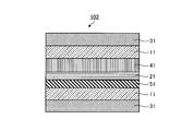
- FIG. 6 is a cross-sectional view schematically illustrating a layer configuration of the heat insulating glass 102 of the second embodiment.
- FIG. 7 is a cross-sectional view schematically showing the layer configuration of the heat insulating glass 103 of the third embodiment.
- FIG. 8 is a graph showing the transmission spectrum of the heat insulating glass 101 of Example 1.
- FIG. 9 is a graph showing the transmission spectrum of the heat insulating glass 103 of Example 3.
- the heat insulating member of the present invention is characterized by having a cholesteric resin layer in which cholesteric regularity is adjusted so that a band that reflects 40% or more of incident light has a wavelength of 200 nm or more in a wavelength region of 800 nm to 1900 nm. That is, by adjusting the cholesteric regularity of the cholesteric resin layer, the heat insulating member of the present invention has a band that reflects 40% or more of incident light in a wavelength region of 800 nm to 1900 nm.
- a layer called a cholesteric resin layer is a resin layer having cholesteric regularity.
- “Cholesteric regularity” means that molecular axes are aligned in a certain direction on one plane, but the direction of molecular axes is slightly different on the next plane, and the angle is further shifted on the next plane.
- the structure is such that the molecular axes are shifted (twisted) one after another in the normal direction of the plane.
- Such a structure in which the direction of the molecular axis is twisted is called a chiral structure.
- the normal line (chiral axis) of the plane is preferably substantially parallel to the thickness direction of the cholesteric resin layer.
- adjusting cholesteric regularity so that a band reflecting 40% or more of incident light in a wavelength region of 800 nm to 1900 nm has 200 nm or more means changing the period of cholesteric regularity to 800 nm to It means forming a cholesteric resin layer having a band reflecting 200% or more of incident light in a wavelength region of 1900 nm of 200 nm or more.
- the upper limit of the bandwidth that reflects 40% or more of incident light is not particularly limited, but can be 1100 nm or less.
- the pitch length p of the chiral structure and the wavelength ⁇ of the circularly polarized light reflected are expressed by the formula ( A) and the formula (B).
- n o represents the minor axis direction of the refractive index of the rod-like liquid crystal compound
- n e represents the refractive index of the long axis of the rod-like liquid crystal compound
- n is (n e + n o) / 2
- p is It represents the pitch length of the chiral structure
- ⁇ represents the incident angle of light (angle from the normal of the surface).
- the center wavelength ⁇ c of the selective reflection band depends on the pitch length p of the chiral structure in the cholesteric resin layer.
- the selected wavelength band can be changed.
- the average transmittance of incident light in a wavelength region of 420 nm to 780 nm, which is a visible light region is 50% or more in order to maintain brightness in a room or in a car.
- the field of view through the glass window is good, and there is a case where a transmittance higher than a predetermined value is required by law (for example, regulation by the Road Traffic Law in Japan). % Or more is preferable, and 70% or more is more preferable.
- the cholesteric resin layer of the heat insulating member of the present invention can be obtained by curing a liquid crystal composition containing a liquid crystal compound.
- a liquid crystalline compound preferably has a refractive index anisotropy ⁇ n of 0.21 or more.
- the upper limit of the refractive index anisotropy ⁇ n is not particularly limited, but can be 0.35 or less.
- the cholesteric resin layer can be formed by applying and drying a liquid crystal composition such as a liquid crystal polymer solution or a polymerizable liquid crystal composition on a substrate.
- a liquid crystal polymer and a liquid crystal polymer solution (coating solution) in which optional components such as a chiral agent, a surfactant, and an alignment modifier are dissolved in a solvent.
- a method of adjusting cholesteric regularity so that a band that reflects 40% or more of incident light has a wavelength of 200 nm or more in a wavelength region of 800 nm to 1900 nm with respect to a coating film obtained by applying a film on a material and drying.
- a polymerizable liquid crystal composition in which an optional component such as a polymerizable liquid crystal compound, a polymerization initiator and a chiral agent, and, if necessary, a surfactant and an alignment regulator are dissolved in a solvent.
- an optional component such as a polymerizable liquid crystal compound, a polymerization initiator and a chiral agent, and, if necessary, a surfactant and an alignment regulator are dissolved in a solvent.
- the method (b) is preferable because the target cholesteric resin layer can be formed more efficiently.
- the thickness of the resulting cholesteric resin layer is preferably 1 ⁇ m to 20 ⁇ m, particularly preferably 3 ⁇ m to 15 ⁇ m.
- the liquid crystal polymer solution that can be used in the method (a) includes a low molecular chiral agent and a nematic liquid crystal polymer; a liquid crystal polymer into which a chiral component is introduced; a nematic liquid crystal polymer and a cholesteric liquid crystal polymer. A mixture; and the like.
- a liquid crystal polymer into which a chiral component has been introduced is a liquid crystal polymer that itself functions as a chiral agent.
- the pitch of the chiral structure of the nematic liquid crystal polymer can be adjusted by changing the mixing ratio thereof.
- para-substituted cyclics that impart nematic orientation consisting of para-substituted aromatic units such as azomethine, azo, azoxy, ester, biphenyl, phenylcyclohexane, and bicyclohexane, and para-substituted cyclohexyl units.
- Cholesteric regularity imparted to a polymer having a compound by a method of introducing an appropriate chiral component comprising a compound having an asymmetric carbon, a low molecular chiral agent, etc. Japanese Patent Laid-Open No. 55-21479, US
- Examples of the terminal substituent at the para position in the para-substituted cyclic compound include a cyano group, an alkyl group, and an alkoxyl group.
- the liquid crystal polymer is not limited by its manufacturing method.
- the liquid crystal polymer can be obtained, for example, by subjecting a monomer having a mesogenic structure to radical polymerization, cationic polymerization, or anionic polymerization.
- a monomer having a mesogenic structure can be obtained, for example, by introducing a mesogenic group into a vinyl monomer such as an acrylic ester or a methacrylic ester directly or via a spacer portion by a known method.
- the liquid crystal polymer can be obtained by adding a vinyl-substituted mesogenic monomer through the Si—H bond of polyoxymethylsilylene in the presence of a platinum-based catalyst; and a phase transfer catalyst via a functional group attached to the main chain polymer.
- It can be obtained by introducing a mesogenic group by the esterification reaction used; or by subjecting a part of malonic acid to a polycondensation reaction between a monomer having a mesogenic group introduced via a spacer part as necessary and a diol.
- chiral agent introduced or contained in liquid crystal polymer As the chiral agent to be introduced or contained in the liquid crystal polymer (that is, the chiral agent introduced as a part of the molecule of the liquid crystal polymer or used as a mixture with the liquid crystal polymer), conventionally known ones can be used. Examples thereof include chiral monomers described in JP-A-6-281814, chiral agents described in JP-A-8-209127, and photoreactive chiral compounds described in JP-A-2003-131187.
- p represents the pitch length of the chiral structure
- c represents the concentration of the chiral agent.
- the pitch length of the chiral structure is a distance in the chiral axis direction until the angle of the molecular axis in the chiral structure gradually shifts as it advances along the plane and then returns to the original molecular axis direction again.
- a base material a well-known and usual material can be used regardless of organic and inorganic, but a transparent base material is preferable.
- a material of the transparent substrate for example, polycycloolefins [for example, Zeonex, Zeonore (registered trademark; manufactured by Zeon Corporation), Arton (registered trademark; manufactured by JSR Corporation), and Apel (registered trademark; (Mitsui Chemicals Co., Ltd.)], transparent resin base materials such as polyethylene terephthalate, polycarbonate, polyimide, polyamide, polymethyl methacrylate, polystyrene, polyvinyl chloride, polytetrafluoroethylene, cellulose, cellulose triacetate, and polyethersulfone.
- polycycloolefins for example, Zeonex, Zeonore (registered trademark; manufactured by Zeon Corporation), Arton (registered trademark; manufactured by JSR Corporation), and Apel (registered trademark; (Mitsui Chemicals Co., Ltd.
- the inorganic material examples include silicon, glass, and calcite.
- the substrate used may be a single layer or a laminate.
- a laminate a combination of an organic material and an inorganic material, a combination of only an organic material, or a combination of only an inorganic material may be used.
- a heat insulating member can be produced by using an organic material as a base material, and the heat insulating member with the base material is laminated on glass.
- the base material may be contained in the heat insulating member as an arbitrary component of the heat insulating member of the present invention.
- an element such as a glass substrate
- an element that is a constituent element of the heat insulating glass of the present invention and is not a constituent element of the heat insulating member of the present invention is used as a base material for forming a cholesteric resin layer.
- the heat insulation member of this invention is comprised and the heat insulation glass of this invention can be comprised by this.
- the cholesteric resin layer (heat insulating layer) can be used by transferring one formed on another substrate in the same manner as in the methods (a) and (b).
- the same substrate as described above can be used, but a transparent substrate is preferable, a transparent organic material is more preferable, and a resin film using this organic material as a film is further preferable.
- an alignment film can be used to form a cholesteric resin layer.
- the alignment film is formed on the surface of the transparent substrate in order to regulate the alignment of the cholesteric resin layer having cholesteric regularity in one direction in the plane.
- the alignment film contains a polymer such as polyimide, polyvinyl alcohol, polyester, polyarylate, polyamideimide, polyetherimide, and polyamide.
- the alignment film can be obtained by applying a solution (composition for alignment film) containing such a polymer on the substrate in the form of a film, drying it, and rubbing it in one direction.
- the thickness of the alignment film is preferably 0.01 to 5 ⁇ m, and more preferably 0.05 to 1 ⁇ m.
- the alignment film or the substrate can be rubbed.
- the rubbing treatment method is not particularly limited, and examples thereof include a method of rubbing the alignment film in a certain direction with a roll made of a synthetic fiber such as nylon or a natural fiber such as cotton or a felt.
- the alignment film is preferably washed with isopropyl alcohol or the like after the rubbing treatment.
- the alignment film may be provided with a function of regulating the orientation of the cholesteric resin layer having cholesteric regularity in one direction in the plane by irradiating the surface of the alignment film with polarized ultraviolet rays. it can.
- the organic solvent solution of the liquid crystal polymer is formed on the substrate by a spin coating method, a roll coating method, a flow coating method, a printing method.
- the coating may be performed by a known coating method such as a dip coating method, a casting film forming method, a bar coating method, a die coating method, or a gravure printing method, and then dried.
- the cholesteric regularity of the liquid crystal polymer layer formed in the form of a film on the substrate is adjusted so that the band that reflects 40% or more of incident light has a wavelength of 200 nm or more in the wavelength region of 800 to 1900 nm.
- the kind and amount of the chiral agent contained in the liquid crystal polymer can be appropriately set, or by selecting an appropriate chiral component to be introduced.
- the mixture of the nematic liquid crystal polymer and the cholesteric liquid crystal polymer can adjust the chiral structure pitch of the nematic liquid crystal polymer by changing the mixing ratio thereof.
- the polymerizable liquid crystal compound used in the method (b) is not particularly limited.
- the ones described in JP-A-2008-291218, JP-A-2008-242349, WO2009 / 133290, Japanese Patent Application No. 2008-170835, and the like can be used.
- the compound represented by the said Formula (1) is preferable, and the compound represented by the said Formula (2) is more preferable.
- at least one of the cholesteric resin layer and the resin layer having a half-wave retardation is formed from a cholesteric liquid crystal composition containing a compound represented by the formula (1). It is preferable that the compound represented by the formula (1) is more preferably a compound represented by the formula (2).
- R 3 represents a hydrogen atom; or an optionally substituted alkyl group having 1 to 10 carbon atoms.
- alkyl group having 1 to 10 carbon atoms which may have a substituent as R 3 include a methyl group, an ethyl group, an n-propyl group, an isopropyl group, and n-butyl. Group, sec-butyl group, t-butyl group, n-pentyl group, n-hexyl group and the like.
- alkyl groups having 1 to 4 carbon atoms such as methyl group, ethyl group, n-propyl group, isopropyl group, and n-butyl group are preferable.
- Examples of the substituent of the alkyl group having 1 to 10 carbon atoms which may have a substituent as R 3 include halogen atoms such as fluorine atom, chlorine atom, bromine atom and iodine atom; methoxy group, ethoxy group, an alkoxy group having 1 to 6 carbon atoms such as an n-propoxy group, an isopropoxy group, an n-butoxy group, a sec-butoxy group, a t-butoxy group, an n-pentyloxy group and an n-hexyloxy group; .
- R 3 is an alkyl group
- the alkyl group includes —O—, —S—, —O—C ( ⁇ O) —, —C ( ⁇ O) —O—, —O—C ( ⁇ O) —O—, —NR 4 —C ( ⁇ O) —, —C ( ⁇ O) —NR 4 —, —NR 4 —, or —C ( ⁇ O) — may be present ( However, this excludes the case where two or more of —O— and —S— are adjacent to each other.)
- R 4 represents a hydrogen atom; or a methyl group, ethyl group, n-propyl group, isopropyl group, n-butyl group, sec-butyl group, t-butyl group, n-pentyl group, n-hexyl group, etc.
- N represents an integer of 2 to 12, and is preferably 6.
- R 1 is preferably a group represented by —C ( ⁇ O) —OR 2 .
- R 2 represents an alkyl group having 1 to 10 carbon atoms, and the alkyl group includes —O—, —S—, —O—C ( ⁇ O) —, —C ( ⁇ O) —O. - May be present (except when two or more of -O- and -S- are present adjacent to each other).
- R 2 is preferably a methyl group.
- the compound represented by the formula (1) can be produced, for example, by a method described in JP-A-2008-291218 by combining known methods in organic synthetic chemistry.
- the liquid crystal polymer compound obtained by polymerizing the compound contained in the polymerizable liquid crystal composition is composed of a homopolymer of a polymerizable liquid crystal compound and two or more kinds of polymerizable liquid crystal compounds.
- examples thereof include a copolymer or a copolymer of a polymerizable liquid crystal compound and another copolymerizable monomer.
- the other copolymerizable monomer is not particularly limited, and examples thereof include 4- (2-methacryloyloxyethyloxy) benzoic acid-4′-methoxyphenyl and 4- (6-methacryloyloxyhexyl).
- the content of other copolymerizable monomers is not particularly limited, but is preferably 50% by weight or less, more preferably 30% by weight or less of the total monomers. Within such a range, a liquid crystalline polymer compound having a high glass transition temperature (Tg) and high film hardness can be obtained.
- Tg glass transition temperature
- the polymerization initiator used in the polymerizable liquid crystal composition used in the method (b) may be either a thermal polymerization initiator or a photopolymerization initiator, but a cholesteric resin layer in which cholesteric rules are adjusted more easily and efficiently. Photoinitiators are preferable.
- photopolymerization initiator examples include polynuclear quinone compounds (US Pat. Nos. 3,046,127 and 2,951,758), oxadiazole compounds (US Pat. No. 4,212,970), ⁇ -carbonyl compounds (US Pat. No. 2,367,661), No. 2,367,670), acyloin ether (US Pat. No. 2,448,828), ⁇ -hydrocarbon substituted aromatic acyloin compound (US Pat. No. 2,722,512), combination of triarylimidazole dimer and p-aminophenyl ketone (U.S. Pat. No. 3,549,367), acridine and phenazine compounds (JP-A-60-105667, U.S. Pat. No. 4,239,850) and the like.
- polynuclear quinone compounds US Pat. Nos. 3,046,127 and 2,951,758
- oxadiazole compounds US Pat. No. 4,212,970
- the blending amount of the polymerization initiator is preferably 1 to 10 parts by weight, and more preferably 1 to 5 parts by weight with respect to 100 parts by weight of the total polymerizable monomer.
- the irradiation energy is preferably from 0.1mJ / cm 2 ⁇ 50J / cm 2, further preferably 0.1mJ / cm 2 ⁇ 800mJ / cm 2.
- the irradiation method of ultraviolet rays is not particularly limited. Further, the ultraviolet irradiation energy is appropriately selected depending on the kind of the polymerizable liquid crystal compound.
- p represents the pitch length of the chiral structure
- c represents the concentration of the chiral agent.
- Examples of other compounding agents contained in the polymerizable liquid crystal composition include surfactants and alignment regulators.
- the surfactant is used to adjust the surface tension of the coating film of the polymerizable liquid crystal composition.
- a nonionic surfactant is preferable, and an oligomer having a molecular weight of about several thousand is preferable.
- the alignment regulator is for controlling the alignment state of the air side surface of the cholesteric resin layer formed on the substrate.
- Examples of the alignment regulator include polyvinyl alcohol, polyvinyl butyral, and modified products thereof.
- the polymerizable liquid crystal composition can be prepared by dissolving a polymerizable liquid crystal compound, a polymerization initiator, a chiral agent, and a surfactant, an alignment adjusting agent, and the like, if necessary, in a solvent.
- Examples of the solvent to be used include organic solvents such as ketones, alkyl halides, amides, sulfoxides, heterocyclic compounds, hydrocarbons, esters, and ethers. Among these, ketones are preferable in consideration of environmental load. Two or more organic solvents may be used in combination.
- the polymerizable liquid crystal composition is formed on a substrate in the same manner as in the method (a) by spin coating, roll coating, flow coating, printing, What is necessary is just to apply
- coat by well-known coating methods, such as the dip coating method, the casting film forming method, the bar coating method, the die coating method, and the gravure printing method, and to dry the obtained coating film.
- the drying temperature is in the range of 40 to 150 ° C.
- the step of adjusting the cholesteric regularity so that a band reflecting 40% or more of incident light in the wavelength region of 800 nm to 1900 nm has 200 nm or more is disclosed in WO 2008/007782. It is preferable to carry out in the same manner as the method disclosed in.
- a polymerizable liquid crystal composition in which a polymerizable liquid crystal compound, a photopolymerization initiator and a chiral agent, and further a surfactant, an alignment regulator, and the like as necessary are dissolved in a solvent is applied in a film form on a substrate, forming a photopolymerizable coating by drying (coating film formation step (I)), the resulting coating film, at a temperature of 20 ⁇ 40 °C, 0.5mJ / cm 2 or more 50 mJ / cm 2
- a process of polymerizing a polymerizable liquid crystal composition by irradiating less than selected ultraviolet rays selective ultraviolet irradiation process (II)
- a process of changing a cycle of cholesteric regularity of the coating film (cholesteric regularity adjusting process (III))
- the step of curing the coating film in which the band reflecting 40% or more of incident light has a wavelength of 200 nm or
- the photopolymerizable coating at a temperature of 20 ⁇ 40 ° C., selectively irradiated ultraviolet less than 0.5 mJ / cm 2 or more 50 mJ / cm 2.
- the integrated light amount is measured using an illuminometer on the substrate surface having a peak sensitivity at the wavelength of the selected ultraviolet ray (specifically, for example, having a peak sensitivity at 360 nm).
- selective UV also referred to as UV for broadening
- UV for broadening refers to a wavelength range or illuminance in which the degree of cross-linking of the liquid crystal in the photopolymerizable coating film described above can be varied in the thickness direction of the film.
- the photopolymerizable coating is not completely cured (100% polymerization) by irradiation with the selective ultraviolet rays.
- the cholesteric regularity is set so that the band that reflects 40% or more of incident light has 200 nm or more. It is easy to adjust.
- the selective ultraviolet ray used in the selective ultraviolet ray irradiation step it is preferable to use an ultraviolet ray having a wavelength range within 100 nm. Specifically, it is preferable to use ultraviolet rays having only wavelengths of 300 nm or more and less than 400 nm.
- the light source a mercury lamp light source, a metal halide lamp light source, or the like can be used.
- the ultraviolet light is used in the selective ultraviolet irradiation process (II) by setting the width of the wavelength range to 100 nm or less by using a bandpass filter under irradiation conditions of 0.5 mJ / cm 2 or more and less than 50 mJ / cm 2. It is preferable. Further, depending on conditions, the wavelength range can be used without controlling. Note that the width of the wavelength range is a half-value width (width of a half value of the peak value of transmittance).
- control of the wavelength range specifically includes, for example, a method using a bandpass filter having a center wavelength of 365 nm, a wavelength range width centered on a wavelength at which the polymerization initiator contained in the coating film exhibits maximum absorption. And the like, and the like.
- the selective ultraviolet rays may be irradiated from the coating film side, from the substrate side, or from both sides of the coating film side and the substrate side. It is preferable to irradiate from the substrate side.
- the hot water irradiating from the coating side needs to control the illuminance / irradiation time stability more severely (specifically, ⁇ 3% or less). Is preferred.
- a step of cooling the photopolymerizable coating film on the substrate to a coating temperature of 20 ° C. to 40 ° C. before the selective ultraviolet irradiation step.
- a light intensity distribution is generated in the thickness direction of the coating film. Cholesteric resin layers having different values can be formed. Examples of the method for cooling the coating film include cooling by cold air supply, cooling by a cooling roll, and the like.
- the pitch of the cholesteric regularity of the coating film is changed (cholesteric regularity adjusting step (III)).
- “Changing the cycle of cholesteric regularity of the coating film” means changing the pitch of the cholesteric resin layer having cholesteric regularity in the thickness direction.
- the method (i) is preferable from the viewpoint of easy operation and effects.
- the temperature is usually about 50 to 115 ° C. for about 0.001 to 20 minutes, preferably about 65 to 115 ° C. for 0.001 to 10 minutes. Preferably, it is at a temperature of 65 to 115 ° C. for 0.01 to 5 minutes.
- the processing temperature and processing time also vary accordingly.
- the selective ultraviolet irradiation step (II) and the cholesteric regularity adjustment step (III) are appropriately adjusted for each number of times in order to adjust the reflection band.
- the number of repetitions is not limited, but is preferably 2 or more from the viewpoint of productivity and equipment.
- the treatment is performed twice or more, the irradiation time can be shortened, so that the degree of polymerization is difficult to increase, and therefore the molecules easily move, so that the pitch of the cholesteric resin layer having cholesteric regularity can be easily controlled. Become.
- steps (II) and (III) means repeating a sequence including the execution of step (II) and the subsequent step (III). That is, when the steps (II) and (III) are repeated twice, the steps (II)-(III)-(II)-(III) are performed in this order. You may perform other processes, such as the said cooling, between these processes.
- the coating film is cured (coating film curing step (IV)).
- the curing method is not particularly limited as long as the coating film is cured and has cholesteric regularity, but it is a method of irradiating the main curing ultraviolet ray so that the integrated light amount becomes 10 mJ / cm 2 or more.
- the main curing ultraviolet ray means an ultraviolet ray set to a wavelength range or illuminance that can completely cure the coating film. It should be noted that it is difficult to vary the degree of cross-linking of the liquid crystal in the coating film in the thickness direction of the film with main curing ultraviolet rays.
- the integrated light quantity of the ultraviolet rays is preferably selected in the range of 10 to 1000 mJ / cm 2 , more preferably 50 to 800 mJ / cm 2 .
- the irradiation direction of the main curing ultraviolet ray may be from either the coating film side or the substrate side, but it is preferable to irradiate from the coating film side from the viewpoint of good irradiation efficiency of ultraviolet rays.
- the main curing ultraviolet ray irradiation is performed in an atmosphere with a small amount of oxygen gas, such as a nitrogen gas atmosphere.
- oxygen gas such as a nitrogen gas atmosphere.
- the oxygen gas concentration at the time of main curing ultraviolet irradiation is preferably 3% or less, more preferably 1% or less, and particularly preferably 500 ppm or less.
- the pitch state of the cholesteric resin layer having cholesteric regularity after the cholesteric regularity adjusting step can be maintained.
- the thickness of the cholesteric resin layer having cholesteric regularity is usually from 1 to 100 ⁇ m, preferably from 1 to 100 ⁇ m, from the viewpoints of preventing disorder of alignment and a decrease in transmittance, and the wide wavelength range (reflection wavelength region) of selective reflection. It is 20 ⁇ m, more preferably 3 to 15 ⁇ m.
- a cholesteric resin layer (hereinafter sometimes referred to as “adjusted cholesteric resin layer”) in which cholesteric regularity is adjusted so that a band reflecting 40% or more of incident light has a wavelength of 200 nm or more in a wavelength region of 800 nm to 1900 nm.
- a coating film forming apparatus suitable for formation a conventionally known apparatus can be used.
- a coating device that continuously feeds the transparent substrate, and a coating head that forms a coating film by applying a photopolymerizable composition on the substrate fed from the feeding device, and the coating film
- Two or more systems comprising: means for cooling the substrate on which the substrate is formed; selective ultraviolet irradiation device for irradiating the coating film with selected ultraviolet rays having a selected wavelength range and / or illuminance; and means for heating the substrate.
- Coating film forming apparatus the feeding device and the coating head are not particularly limited, and known ones can be used.
- a means to cool the base material in which the coating film was formed in this invention can comprise with a cooling zone apparatus, a cooling roll, etc., and it is preferable to comprise from a cooling zone apparatus.
- the said cooling means can be used as the apparatus which encloses a part of conveyance path
- FIGS. 1 Examples of the heat insulating member of the present invention (layer configuration sectional views) are shown in FIGS. 1 includes two transparent substrates 3 and two adjustment cholesteric resin layers 1 formed on each of the transparent substrates, and between the two cholesteric resin layers. Is a heat insulating member 10A including a resin layer 2 having a phase difference of 1 ⁇ 2 wavelength.
- the one shown in FIG. 3 includes two transparent substrates 3 each of which is a laminate of transparent substrates 3a and 3b, and an adjusted cholesteric resin layer 1 formed on each of the transparent substrates, and
- the heat insulating member 10 ⁇ / b> C includes the resin layer 2 having a phase difference of 1 ⁇ 2 wavelength and the intermediate film 4 between the two cholesteric resin layers.
- 3a is glass and 3b is an organic material
- the organic material and the heat insulating member are independently manufactured, and the heat insulating glass can be manufactured by laminating with the glass.
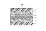
- FIG. 4 shows a heat insulating member 10D when the air layer 6 is further provided in the heat insulating glass shown in FIG.
- the heat insulating member of the present invention is preferably used as heat insulating glass that is attached to glass to form heat insulating glass, or disposed inside laminated glass.
- Laminated glass refers to glass that has been heat-sealed by placing an intermediate film between two sheets of glass, or glass that has an air layer provided between two sheets of glass. It can be set as heat insulation glass by arrange
- the interlayer film can be arranged so that the glass and the layers constituting the heat insulating member or the heat insulating member of the present invention can be integrated.
- the heat insulating glass of the present invention can be, for example, the laminated glass of FIG. A known transparent resin can be used for the interlayer film.
- the heat insulating glass of the present invention includes two glass substrates and the heat insulating member of the present invention provided between them.
- the heat insulating glass of the present invention may further have any other layer between two glass substrates.
- the heat-resistant glass of the present invention has two transparent resin films between two glass substrates, and includes the heat insulating member of the present invention between the two transparent resin films.
- the heat-resistant glass of the present invention may be provided with an intermediate film such as those described above between two glass substrates, and the intermediate film exists between the glass substrate and the heat insulating member. As shown in the examples of FIGS. 2 to 4, they may be provided between the layers constituting the heat insulating member.
- the heat-resistant glass of the present invention may have an air layer between two glass substrates, for example, in the above-described manner.
- the reflectance in the selective reflection band per cholesteric resin layer is 50% at the maximum, and further higher reflectance is required for the heat insulating member as a whole.
- a method of making the reflectance of the selective reflection band larger than 50% there is a method of disposing a retardation layer having a half wavelength of the selective reflection band between two cholesteric resin layers in the same spiral direction.
- the arrangement of the 1 ⁇ 2 wavelength layer between the two cholesteric layers can be achieved by using or forming a known retardation layer as the 1 ⁇ 2 wavelength layer. For example, a film obtained by stretching a transparent resin, a layer in which an oriented liquid crystal layer is fixed, or the like can be used.
- the resin layer having a phase difference of 1 ⁇ 2 wavelength (1 ⁇ 2 wavelength layer) can be formed using a conventionally known 1 ⁇ 2 wavelength plate.
- the half-wave plate is obtained, for example, by stretching a film made of a transparent resin, and has a slow axis in the direction of 15 ° ⁇ 7 ° or ⁇ 15 ° ⁇ 7 ° with respect to the width direction. It is what you have.
- the transparent resin constituting the half-wave plate is not particularly limited as long as it has a thickness of 1 mm and a total light transmittance of 80% or more.
- An acetate resin such as triacetyl cellulose, a polyester resin, or a polyether sulfone is not limited.
- the unstretched film made of a transparent resin to be used is made of a transparent resin, and the resin may contain, as necessary, an antioxidant, a heat stabilizer, a light stabilizer, an ultraviolet absorber, an antistatic agent, and a dispersant. , Chlorine scavengers, flame retardants, crystallization nucleating agents, antiblocking agents, antifogging agents, mold release agents, pigments, organic or inorganic fillers, neutralizing agents, lubricants, decomposition agents, metal deactivators, contamination
- Known additives such as an inhibitor, an antibacterial agent and a thermoplastic elastomer can be added as long as the effects of the present invention are not impaired.
- the addition amount of these additives is usually 0 to 5 parts by weight, preferably 0 to 3 parts by weight with respect to 100 parts by weight of the transparent resin.
- the half-wave plate is obtained by stretching an unstretched film made of a transparent resin and adjusting the stretching ratio.
- the method for obtaining an unstretched film made of a transparent resin is not particularly limited, and a known molding method such as a melt-extrusion molding method, a press molding method, a hot melt molding method such as an inflation method, or a solution casting method is adopted. Can do. Each molding condition may be appropriately adjusted according to the glass transition temperature of the transparent resin to be used, the solvent, and the like.
- the thickness of the half-wave plate is usually 10 to 300 ⁇ m, preferably 30 to 200 ⁇ m.
- the fixed layer of the aligned liquid crystal layer constituting the 1 ⁇ 2 wavelength layer is not particularly limited as long as it is fixed in the use environment of the heat insulating member of the present invention. After the alignment, it can be quenched and fixed at a low temperature, or the polymerizable liquid crystal can be cured by heat and / or light after the alignment treatment.
- a polymer liquid crystal or a polymerizable liquid crystal a rod-like liquid crystal compound that exhibits a nematic phase or a smectic phase is preferably used, and a rod-like liquid crystal compound that exhibits a nematic phase is more preferably used.
- d Re / ⁇ n by the desired retardation Re and the refractive index anisotropy ⁇ n of the liquid crystal compound used.
- the retardation layer of Re560 nm is formed by setting the thickness to 4 ⁇ m.
- Such polymerizable liquid crystal is preferably polyfunctional, and can be formed into a highly heat-resistant retardation layer by crosslinking during curing.
- the 1/2 wavelength layer formed from the cholesteric liquid crystal composition containing the compound represented by Formula (1) demonstrated above can also be used preferably.
- the half-wave layer may be directly laminated on the cholesteric resin layer, or may be laminated via an adhesive, an adhesive, or an alignment film.
- Known materials can be used for the pressure-sensitive adhesive and the adhesive, and examples thereof include a thermoplastic resin type and a thermosetting resin type.
- the pressure-sensitive adhesive or adhesive used for forming the pressure-sensitive adhesive layer is not particularly limited as long as it is transparent.
- a thermoplastic resin type or a thermosetting resin type may be used.
- the thermoplastic resin-based pressure-sensitive adhesive or adhesive include vinyl acetate, polyvinyl alcohol, polyvinyl acetal, vinyl chloride, acrylic, polyamide, polyethylene, and cellulose. Among these, an acrylic pressure-sensitive adhesive or an adhesive is preferable.
- a copolymer of ethyl acrylate, butyl acrylate, 2-ethylhexyl acrylate, and the like with methacrylic acid ester, styrene, acrylonitrile, vinyl acetate, or the like is preferable. is there.
- thermosetting resin-based pressure-sensitive adhesive or adhesive examples include melamine-based, phenol-based, resorcinol-based, polyester-based, polyurethane-based, epoxy-based, and polyaromatic-based ones.
- a polyurethane-based pressure-sensitive adhesive or adhesive, or an epoxy-based pressure-sensitive adhesive or adhesive is preferable.
- a polyurethane-based pressure-sensitive adhesive or adhesive mainly comprises a polymer obtained by reacting isocyanate and alcohol with an excess of alcohol, and is suitably used as a hot melt or a solvent-soluble type.
- the polyurethane pressure-sensitive adhesive or adhesive is easily cured at room temperature using a curing agent such as an amine curing agent or by heating.
- These pressure-sensitive adhesives or adhesives may be used in the form of films, aqueous solutions, emulsions and the like.
- the thickness of the pressure-sensitive adhesive layer (or adhesive layer) 5 may be adjusted as appropriate, but is usually in the range of 1 to 200 ⁇ m, preferably 10 to 200 ⁇ m, more preferably 50 to 150 ⁇ m.
- the alignment film is provided for the purpose of improving the orientation and improving the adhesion between the cholesteric resin layer and the 1 ⁇ 2 wavelength layer when a liquid crystal layer having a retardation of 1 ⁇ 2 wavelength is formed on the cholesteric resin layer. I can do it.
- a known material can be used for the alignment film, and examples thereof include polymers such as polyimide, polyvinyl alcohol, polyester, polyarylate, polyamideimide, polyamide, and polyetherimide.
- the alignment film can be obtained by coating a solution containing such a polymer on a substrate such as a cholesteric resin layer, drying it, and rubbing it in one direction.
- the thickness of the alignment film is preferably 0.01 to 5 ⁇ m, more preferably 0.05 to 1 ⁇ m.
- the heat insulating member of the present invention can highly reflect infrared rays in the wavelength region of about 900 to about 1300 nm where the amount of solar energy is high even with a small number of cholesteric resin layers, and has a light transmittance in the visible light region. It is high, can be produced industrially advantageously, and has high practicality.
- the heat insulating member of the present invention can highly reflect infrared rays having a high solar energy amount and has high light transmittance in the visible light region, heat insulating windows for automobiles, railways and houses, heat insulating materials for building materials, and electronic equipment It can be suitably used as a heat insulating material.
- part relating to the component amount ratio represents part by weight unless otherwise specified.
- Example 1 Formation of Cholesteric Resin Layer with Adjusted Cholesteric Regularity 30 parts of polymerizable liquid crystal compound (3) represented by the following formula (compound (3) is prepared by the method described in JP-A-2008-291218) Synthesized, ⁇ n is 0.22),
- LC756 1.2 parts of chiral agent
- polymerization initiator trade name “Irgacure OXEO2”, manufactured by Ciba Japan
- surfactant fluorinated surfactant, Cholesteric liquid crystal composition having a solid content concentration (ratio of components other than cyclopentanone as a solvent) of 40% by mixing 0.04 part of a trade name “Futagent 209F” (manufactured by Neos) and 60 parts of cyclopentanone.
- Futagent 209F trade name “manufactured by Neos
- the prepared cholesteric liquid crystal composition was applied to a surface having an alignment film of an alignment-treated glass substrate with a polyimide alignment film (Eetchy Co., Ltd., thickness: 1.1 mm) using a # 20 wire bar. Then, an alignment treatment was performed for 2 minutes to form a cholesteric liquid crystal composition layer having a thickness of 10 ⁇ m. Next, after irradiating 15 mJ / cm 2 of ultraviolet rays from the glass substrate side, the substrate was heated at 100 ° C. for 1 minute. This was cooled to 30 ° C., irradiated again with 15 mJ / cm 2 of ultraviolet light from the glass substrate side of the cholesteric liquid crystal composition layer, and then heated at 100 ° C. for 1 minute.
- ultraviolet rays of 2000 mJ / cm 2 are irradiated from the layer side of the cholesteric liquid crystal composition to form a resin layer with adjusted cholesteric regularity on the glass substrate, thereby obtaining a multilayer product composed of the glass substrate and the cholesteric resin layer. It was.
- a polarizing microscope Nekon Corporation, polarizing microscope ECLIPSE E600-POL
- there was no alignment defect and a transparent cholesteric resin layer without haze was formed.
- Two multilayers were prepared, one was used in the following step (1-2), the other was used in the following step (1-3), and these were finally bonded.
- the nematic liquid crystal composition was prepared using a cholesteric resin layer.
- a nematic liquid crystal composition layer having a thickness of 4 ⁇ m was formed by applying the film on the surface and performing an alignment treatment at 85 ° C. for 2 minutes.
- an ultraviolet ray of 2000 mJ / cm 2 is irradiated from the layer side of the nematic liquid crystal composition to form a nematic resin layer on the cholesteric resin layer, thereby obtaining a multi-layered product including a glass substrate, a cholesteric resin layer and a nematic resin layer.
- FIG. 1 shows a cross-sectional view of the layer structure of the heat insulating glass 101.
- a transmission spectrum and a reflection spectrum of 420 nm to 1900 nm of the heat insulating glass 101 obtained were measured with an ultraviolet-visible-near infrared spectrophotometer (manufactured by JASCO Corporation, V-570), and an average transmittance of 420 nm to 780 nm which is visible light Then, the central wavelength and the band width of the selective reflection band where the reflectance is 40% or more were examined.
- the obtained spectrum is shown in FIG. 8 and the numerical results are shown in Table 1.
- Thermal insulation rate (%) (Amount of energy reflected 900 to 1300 nm / total energy amount 900 to 1300 nm) ⁇ 100
- Example 2 The cholesteric resin layer side of the multilayer produced in (1-1) of Example 1 was corona-treated, and a 5% aqueous solution of polyvinyl alcohol was applied to the cholesteric resin layer using a # 2 wire bar. After drying at 100 ° C. for 1 minute to form an alignment film having a film thickness of 0.1 ⁇ m, the alignment film surface was rubbed to obtain a multi-layered product composed of a glass substrate, a cholesteric resin layer and an alignment film. A half-wave layer was formed on the alignment film in the same manner as in Example 1-2 (1-2), and the heat insulating glass 102 was produced in the same manner as in Example 1.
- Example 3 The cholesteric resin layer side of each of the two multilayers prepared in (1-1) of Example 1 was corona treated.
- Retardation 550 nm retardation film (Zeonor (registered trademark; manufactured by Nippon Zeon Co., Ltd.) stretched film, thickness 160 ⁇ m) was subjected to corona treatment on both sides.
- a polyvinyl butyral sheet was disposed between the cholesteric resin layer and the retardation film so that the cholesteric resin layer was on the inner side, and the fusion treatment was performed.
- the multilayer layer, the retardation film, the polyvinyl butyral sheet (thickness 0.7 mm), the retardation film, and the multilayer layer are in this order, and the surface of the multilayer layer on the cholesteric resin layer side is in contact with the retardation film.
- the fusion treatment was performed.
- the heat insulating glass 103 was produced.
- a cross-sectional view of the layer structure of the heat insulating glass 103 is shown in FIG.
- the transmittance of the heat insulating glass 103 was measured and the heat insulating rate was calculated.
- the obtained spectrum is shown in FIG. 9 and the numerical results are shown in Table 1.
- Example 4 Each heat insulating glass produced in Example 1, Example 2, and Example 3 was treated at 130 ° C. for 3 hours, and then the transmission spectrum was measured. Calculation of average visible light transmittance and thermal insulation rate was performed. The numerical results are shown in Table 2.
Landscapes
- Polarising Elements (AREA)
- Thermal Insulation (AREA)
- Laminated Bodies (AREA)
- Optical Filters (AREA)
Abstract
800nm~1900nmの波長領域において、入射光の40%以上を反射する帯域が200nm以上有するようにコレステリック規則性が調整された2層のコレステリック樹脂層と、該2層のコレステリック樹脂層の間に1/2波長の位相差を有する樹脂層を備えることを特徴とする断熱部材、並びにこれを備える断熱ガラス。
Description
本発明は、太陽エネルギー量の高い約900~約1300nm付近の波長領域にある赤外線の反射率が高く、かつ、可視光線領域の光線透過率の高いコレステリック樹脂層を有する断熱部材に関する。
近年、省エネルギー化を推進する観点から、冷暖房効率を向上させる赤外線の断熱層が注目されている。赤外線の断熱層を自動車やビルの窓ガラスに使用することを考慮する場合、可視光線領域である約400nm~約750nmの波長領域においては、光線透過率を高めることが重要であるが、太陽エネルギー量の高い約900~約1300nmの領域にある近赤外線においては、断熱効果の観点から、より多く反射することが望ましい。近赤外線領域は可視光線領域に極めて近い波長域であるため、これら両者のバランスを達成するためには、用いる断熱層の反射特性が、近赤外線領域と可視光線領域とにおいて極めて鋭く変化する必要がある。
しかしながら、従来の断熱層の材料では、可視光線領域と近赤外線領域との間において、ブロードな反射特性の変化しか得ることができないので、両者のバランスを達成することは困難であった。
しかしながら、従来の断熱層の材料では、可視光線領域と近赤外線領域との間において、ブロードな反射特性の変化しか得ることができないので、両者のバランスを達成することは困難であった。
この課題を解決する方策の一つとして、コレステリック液晶を用いる断熱層が知られている。コレステリック液晶によって反射される光は以下の式によって決まり、すなわち、選択反射の中心波長λは、λ=n×p(式中、nはコレステリック液晶層の平均屈折率、pはらせん1周期の長さ)で表され、その反射帯域の帯域幅Δλは、Δλ=Δn×p(式中、Δnはコレステリック液晶層の屈折率異方性、pはらせん1周期の長さ)で表される。また、選択反射の反射係数Qは、Q=π×Δn/nで表される。つまり、コレステリック液晶を用いて近赤外線及び赤外線を十分に反射させるためにはΔnの高い、すなわち通常Δn0.21以上のコレステリック液晶を用いて、厚い層、すなわち通常8μm以上の層を形成することが必要である。しかしながら、配向欠陥なくコレステリック液晶を配向できるのはせいぜい6μm程度であり、十分に近赤外線及び赤外線を反射することができない。また、これ以上の膜厚になると配向欠陥が生じてヘイズを高くしてしまう問題がある。特許文献1ではヘイズ3%未満の赤外線反射フィルムが開示されているが、赤外線を反射するコレステリック層の厚みは最大で6μm程度であり、ヘイズは低く抑えられているが赤外線の反射率が低く、十分な断熱機能を有していない。また、コレステリック液晶のΔnが0.21未満であり、反射帯域幅も狭い欠点がある。特許文献2では1/2λ波長板を2層のコレステリック層間に配置することで反射率を高める方法が開示されているが、コレステリック液晶のΔnが0.21未満であるため反射帯域幅が狭く、十分な断熱機能を有していない。特許文献3では、選択反射帯域の異なるコレステリック液晶ポリマーを5層積層することで広い反射帯域幅が得られている。しかし、液晶ポリマーを使用しているため配向処理に長時間を要すること、さらには5層ものコレステリック液晶層が必要であり、生産性に欠ける問題があった。
本発明は、かかる従来技術の実情に鑑みてなされたものであり、コレステリック樹脂層の数が少なくても、太陽エネルギー量の高い約900~約1300nm付近の波長領域にある赤外線の反射率が高く、かつ、可視光線領域の光線透過率の高い(すなわち、極めて鋭い反射特性変化を有する)コレステリック樹脂層を有する断熱部材を提供することを課題とする。
本発明者は、上記課題を解決すべく鋭意研究を重ねた結果、コレステリック規則性を調整して、800nm~1900nmの波長領域において、入射する放射の少なくとも40%以上を反射する帯域が200nm以上有するようにコレステリック規則性が調整されたコレステリック樹脂層と該2層のコレステリック樹脂層の間に1/2波長の位相差を有する樹脂層を用いると、該コレステリック樹脂層の数が少なくても、赤外線領域と可視光線領域との間において極めて鋭い反射特性変化を有し、耐熱性に優れた実用的な断熱部材が得られることを見出し、本発明を完成するに至った。
かくして、本発明によれば、下記〔1〕~〔9〕が提供される。
〔1〕800nm~1900nmの波長領域において、入射光の40%以上を反射する帯域が200nm以上有するようにコレステリック規則性が調整された2層のコレステリック樹脂層と、該2層のコレステリック樹脂層の間に1/2波長の位相差を有する樹脂層を備えることを特徴とする断熱部材。
〔1〕800nm~1900nmの波長領域において、入射光の40%以上を反射する帯域が200nm以上有するようにコレステリック規則性が調整された2層のコレステリック樹脂層と、該2層のコレステリック樹脂層の間に1/2波長の位相差を有する樹脂層を備えることを特徴とする断熱部材。
〔2〕前記1/2波長の位相差を有する樹脂層がネマチック配向を有する樹脂層、または透明樹脂を延伸したフィルムであることを特徴とする〔1〕に記載の断熱部材。
〔3〕前記コレステリック樹脂層が、屈折率異方性Δnが0.21以上の液晶性化合物を含む液晶組成物を硬化してなる樹脂層であることを特徴とする〔1〕又は〔2〕に記載の断熱部材。
〔3〕前記コレステリック樹脂層が、屈折率異方性Δnが0.21以上の液晶性化合物を含む液晶組成物を硬化してなる樹脂層であることを特徴とする〔1〕又は〔2〕に記載の断熱部材。
〔4〕420~780nmの波長領域における入射光の平均透過率が50%以上であることを特徴とする〔1〕~〔3〕のいずれかに記載の断熱部材。
〔5〕前記コレステリック樹脂層及び前記1/2波長の位相差を有する樹脂層の少なくとも1層が、式(1)
〔5〕前記コレステリック樹脂層及び前記1/2波長の位相差を有する樹脂層の少なくとも1層が、式(1)

(式中、R1は、水素原子、ハロゲン原子、炭素数1~10のアルキル基、-OR3、-O-C(=O)-R3、又は、-C(=O)-OR3を表す。ここで、R3は、水素原子又は置換基を有してもよい炭素数1~10のアルキル基を表す。R3がアルキル基である場合、当該アルキル基には、-O-、-S-、-O-C(=O)-、-C(=O)-O-、-O-C(=O)-O-、-NR4-C(=O)-、-C(=O)-NR4-、-NR4-、または-C(=O)-が介在していてもよい(ただし、-O-及び-S-がそれぞれ2以上隣接して介在する場合を除く。)。ここで、R4は、水素原子または炭素数1~6のアルキル基を表す。nは2から12の整数を表す。)
で表される化合物を含有するコレステリック液晶組成物から形成されたものであることを特徴とする〔1〕~〔4〕のいずれかに記載の断熱部材。
で表される化合物を含有するコレステリック液晶組成物から形成されたものであることを特徴とする〔1〕~〔4〕のいずれかに記載の断熱部材。
〔6〕前記式(1)で表される化合物が、式(2)

(式中、R2は炭素数1~10のアルキル基を表し、当該アルキル基には、-O-、-S-、-O-C(=O)-、-C(=O)-O-が介在していてもよい(ただし、-O-および-S-がそれぞれ2以上隣接して介在する場合を除く。)。)
で表される化合物であることを特徴とする〔5〕に記載の断熱部材。
で表される化合物であることを特徴とする〔5〕に記載の断熱部材。
〔7〕2枚のガラス基板、およびそれらの間に設けられた〔1〕~〔6〕のいずれかに記載の断熱部材を備えることを特徴とする断熱ガラス。
〔8〕前記2枚のガラス基板の間にさらに合わせガラス用中間膜を備えることを特徴とする〔7〕に記載の断熱ガラス。
〔9〕前記2枚のガラス基板の間に空気層を備えることを特徴とする〔7〕に記載の断熱ガラス。
〔8〕前記2枚のガラス基板の間にさらに合わせガラス用中間膜を備えることを特徴とする〔7〕に記載の断熱ガラス。
〔9〕前記2枚のガラス基板の間に空気層を備えることを特徴とする〔7〕に記載の断熱ガラス。
本発明によれば、コレステリック樹脂層の数が2層といった少ない数であっても、太陽エネルギー量の高い約900~約1300nm付近の波長領域にある赤外線を高度に反射でき、かつ、可視光線領域の光線透過率の高い、実用的な断熱部材が提供される。
以下、本発明を詳細に説明する。
本発明の断熱部材は、800nm~1900nmの波長領域において、入射光の40%以上を反射する帯域が200nm以上有するようにコレステリック規則性が調整されたコレステリック樹脂層を有することを特徴とする。
即ち、コレステリック樹脂層のコレステリック規則性が調整されることにより、本発明の断熱部材は、800nm~1900nmの波長領域において、入射光の40%以上を反射する帯域を200nm以上有する。
本発明の断熱部材は、800nm~1900nmの波長領域において、入射光の40%以上を反射する帯域が200nm以上有するようにコレステリック規則性が調整されたコレステリック樹脂層を有することを特徴とする。
即ち、コレステリック樹脂層のコレステリック規則性が調整されることにより、本発明の断熱部材は、800nm~1900nmの波長領域において、入射光の40%以上を反射する帯域を200nm以上有する。
本願においてコレステリック樹脂層と呼ぶ層は、コレステリック規則性を有する樹脂層である。「コレステリック規則性」とは、一平面上では分子軸が一定の方向に並んでいるが、次の平面では分子軸の方向が少し角度をなしてずれ、さらに次の平面ではさらに角度がずれるという具合に、該平面の法線方向に分子軸の角度が次々にずれて(ねじれて)いく構造である。このように分子軸の方向がねじれてゆく構造はカイラルな構造と呼ばれる。該平面の法線(カイラル軸)はコレステリック樹脂層の厚さ方向に略平行になっていることが好ましい。
また、「800nm~1900nmの波長領域において、入射光の40%以上を反射する帯域が200nm以上有するようにコレステリック規則性を調整する」とは、コレステリック規則性の周期を変化させることにより、800nm~1900nmの波長領域において、入射光の40%以上を反射する帯域を200nm以上有するコレステリック樹脂層を形成することをいう。
入射光の40%以上を反射する帯域の広さの上限は、特に限定されないが、1100nm以下とすることができる。
入射光の40%以上を反射する帯域の広さの上限は、特に限定されないが、1100nm以下とすることができる。
コレステリック規則性を持つコレステリック樹脂層に光が入射すると、特定波長領域の左回りまたは右回りの何れかの円偏光のみが反射される。反射された円偏光以外の光は透過する。この円偏光が反射される特定波長領域が選択反射帯域である。
カイラル構造において分子軸が捩れる時の回転軸を表す螺旋軸と、コレステリック樹脂層の法線とが平行である場合、カイラル構造のピッチ長pと反射される円偏光の波長λとは式(A)および式(B)の関係を有する。
式(A):λc=n×p×cosθ
式(B):no×p×cosθ≦λ≦ne×p×cosθ
式(B):no×p×cosθ≦λ≦ne×p×cosθ
式中、noは棒状液晶化合物の短軸方向の屈折率を表し、neは棒状液晶化合物の長軸方向の屈折率を表し、nは(ne+no)/2であり、pはカイラル構造のピッチ長を表し、θは光の入射角(面の法線からの角度)を表す。
すなわち、選択反射帯域の中心波長λcは、コレステリック樹脂層におけるカイラル構造のピッチ長pに依存する。このカイラル構造のピッチ長を変えることによって、選択波長帯域を変えることができる。
本発明においては、室内あるいは車内などにおいて、明度を維持するために、可視光線の領域である420nm~780nmの波長領域における入射光の平均透過率が、50%以上であることが好ましい。さらに、自動車においては、ガラス窓を通しての視界が良好であることが好ましく、且つ法律により所定以上の透過率が求められる場合もある(例えば日本における道路交通法による規制)ため、平均透過率は60%以上であることが好ましく、70%以上であることがさらに好ましい。
(コレステリック樹脂層)
本発明の断熱部材が有するコレステリック樹脂層は、液晶性化合物を含む液晶組成物を硬化して得ることができる。かかる液晶性化合物は、その屈折率異方性Δnが0.21以上のものであることが好ましい。また、屈折率異方性Δnの上限は、特に限定されないが、0.35以下とすることができる。
具体的には、コレステリック樹脂層は、液晶ポリマー溶液、又は重合性液晶組成物等の液晶組成物を、基材上に塗布・乾燥することにより形成することができる。
本発明の断熱部材が有するコレステリック樹脂層は、液晶性化合物を含む液晶組成物を硬化して得ることができる。かかる液晶性化合物は、その屈折率異方性Δnが0.21以上のものであることが好ましい。また、屈折率異方性Δnの上限は、特に限定されないが、0.35以下とすることができる。
具体的には、コレステリック樹脂層は、液晶ポリマー溶液、又は重合性液晶組成物等の液晶組成物を、基材上に塗布・乾燥することにより形成することができる。
より具体的には、例えば、(a)液晶ポリマー、並びに必要に応じてカイラル剤、界面活性剤、及び配向調整剤等の任意の成分を溶剤に溶解させた液晶ポリマー溶液(塗布液)を基材上に膜状に塗布し、乾燥させ、得られた塗膜について、800nm~1900nmの波長領域において、入射光の40%以上を反射する帯域が200nm以上有するようにコレステリック規則性を調整する方法、或いは、(b)重合性液晶化合物、重合開始剤およびカイラル剤、並びに必要に応じて界面活性剤、及び配向調整剤等の任意の成分を溶剤に溶解させた重合性液晶組成物(塗布液)を得、これを基材上に膜状に塗布し、乾燥させ、得られた塗膜を重合した後、800nm~1900nmの波長領域において、入射光の40%以上を反射する帯域が200nm以上有するようにコレステリック規則性を調整する方法によって形成することができる。
これらの中でも、より効率よく目的とするコレステリック樹脂層を形成できることから、(b)の方法が好ましい。
(a)、(b)いずれの方法においても、得られるコレステリック樹脂層の厚みは、1μm~20μmが好ましく、3μm~15μmが特に好ましい。
(a)、(b)いずれの方法においても、得られるコレステリック樹脂層の厚みは、1μm~20μmが好ましく、3μm~15μmが特に好ましい。
(液晶ポリマー溶液)
(a)の方法で用いることができる液晶ポリマー溶液としては、低分子カイラル剤及びネマチック液晶ポリマーを含有するもの;カイラル成分が導入された液晶ポリマーを含有するもの;ネマチック液晶ポリマーとコレステリック液晶ポリマーの混合物;等が挙げられる。カイラル成分が導入された液晶ポリマーとは、それ自体がカイラル剤の機能を果たす液晶ポリマーである。ネマチック液晶ポリマーとコレステリック液晶ポリマーの混合物は、それらの混合比率を変えることによって、ネマチック液晶ポリマーのカイラル構造のピッチを調整することができるものである。
(a)の方法で用いることができる液晶ポリマー溶液としては、低分子カイラル剤及びネマチック液晶ポリマーを含有するもの;カイラル成分が導入された液晶ポリマーを含有するもの;ネマチック液晶ポリマーとコレステリック液晶ポリマーの混合物;等が挙げられる。カイラル成分が導入された液晶ポリマーとは、それ自体がカイラル剤の機能を果たす液晶ポリマーである。ネマチック液晶ポリマーとコレステリック液晶ポリマーの混合物は、それらの混合比率を変えることによって、ネマチック液晶ポリマーのカイラル構造のピッチを調整することができるものである。
また、アゾメチン形、アゾ形、アゾキシ形、エステル形、ビフェニル形、フェニルシクロヘキサン形、およびビシクロヘキサン形のようなパラ置換芳香族単位やパラ置換シクロヘキシル単位等からなるネマチック配向性を付与するパラ置換環状化合物を有するポリマーに、不斉炭素を有する化合物等からなる適宜なカイラル成分や低分子カイラル剤等を導入する方法等により、コレステリック規則性を付与したもの(特開昭55-21479号公報、米国特許第5332522号公報等を参照)も用いることができる。なお、パラ置換環状化合物におけるパラ位の末端置換基としては、シアノ基やアルキル基、アルコキシル基等が挙げられる。
液晶ポリマーはその製法によって制限されない。液晶ポリマーは、例えば、メソゲン構造を有するモノマーをラジカル重合、カチオン重合またはアニオン重合することによって得られる。メソゲン構造を有するモノマーは、例えばアクリル酸エステルやメタクリル酸エステルのようなビニル系モノマーに、直接にまたはスペーサー部を介してメソゲン基を公知の方法で導入することによって得ることができる。また、液晶ポリマーは、ポリオキシメチルシリレンのSi-H結合を介し白金系触媒の存在下にビニル置換メソゲンモノマーを付加反応させることによって;主鎖ポリマーに付与した官能基を介して相間移動触媒を用いたエステル化反応によりメソゲン基を導入することによって;又はマロン酸の一部に必要に応じスペーサー部を介してメソゲン基を導入したモノマーとジオールとを重縮合反応させることによって得ることができる。
(液晶ポリマーに導入または含有させるカイラル剤)
液晶ポリマーに導入または含有させるカイラル剤(即ち、液晶ポリマーの分子の一部として導入するか、液晶ポリマーと共に混合物として用いるカイラル剤)としては、従来公知のものを使用することができる。例えば、特開平6-281814号公報に記載されたカイラルモノマー、特開平8-209127号公報に記載されたカイラル剤、特開2003-131187号公報に記載の光反応型カイラル化合物等が挙げられる。
液晶ポリマーに導入または含有させるカイラル剤(即ち、液晶ポリマーの分子の一部として導入するか、液晶ポリマーと共に混合物として用いるカイラル剤)としては、従来公知のものを使用することができる。例えば、特開平6-281814号公報に記載されたカイラルモノマー、特開平8-209127号公報に記載されたカイラル剤、特開2003-131187号公報に記載の光反応型カイラル化合物等が挙げられる。
またカイラル剤としては、カイラル剤の添加によって意図しない相転移温度の変化が生じることを避けるために、カイラル剤自身が液晶性を示すものが好ましい。さらに、経済性の観点からは、液晶ポリマーを捩じる効率を表す指標であるHTP(=1/p・c)の大きなものが好ましい。ここで、pはカイラル構造のピッチ長を表し、cはカイラル剤の濃度を表す。カイラル構造のピッチ長とは、カイラル構造において分子軸の方向が平面を進むに従って少しずつ角度がずれていき、そして再びもとの分子軸方向に戻るまでのカイラル軸方向の距離のことである。
基材としては、有機、無機を問わず、公知慣用の材質のものを使用することができるが、透明基材が好ましい。透明基材の材質としては、例えば、有機材料としてはポリシクロオレフィン〔例えば、ゼオネックス、ゼオノア(登録商標;日本ゼオン株式会社製)、アートン(登録商標;JSR社製)、及びアペル(登録商標;三井化学社製)〕、ポリエチレンテレフタレート、ポリカーボネート、ポリイミド、ポリアミド、ポリメタクリル酸メチル、ポリスチレン、ポリ塩化ビニル、ポリテトラフルオロエチレン、セルロース、三酢酸セルロース、ポリエーテルスルホン等の透明樹脂基材が挙げられ、無機材料としてはシリコン、ガラス、方解石等が挙げられる。
また、用いる基材は、単層のものであっても、積層体であってもよい。積層体の場合、有機材料と無機材料の組み合わせ、有機材料のみの組み合わせ、無機材料のみの組み合わせであってもよい。例えば、有機材料を基材として使用して断熱部材を作製し、その基材付の断熱部材をガラスに積層して、断熱ガラスを作製することもできる。
ここで基材は、本発明の断熱部材の任意の構成要素として断熱部材に含まれていてもよい。
また、本発明の断熱部材と、それ以外の構成要素としてのガラス基板とを組み合わせて、後述する本発明の断熱ガラスを構成してもよい。例えば、本発明の断熱ガラスの構成要素であって本発明の断熱部材の構成要素以外の要素(ガラス基板等)を、コレステリック樹脂層を形成するための基材として用い、この基材の上に本発明の断熱部材を構成し、これにより本発明の断熱ガラスを構成することができる。
本発明においては、コレステリック樹脂層(断熱層)は、(a)及び(b)の方法と同様にして他の基材に形成したものを転写して用いることもできる。
他の基材としては、前述した基材と同様のものが使用できるが、透明基材が好ましく、透明有機材料がより好ましく、更にはこの有機材料をフィルムとした樹脂フィルムが更に好ましい。
他の基材としては、前述した基材と同様のものが使用できるが、透明基材が好ましく、透明有機材料がより好ましく、更にはこの有機材料をフィルムとした樹脂フィルムが更に好ましい。
本発明においては、コレステリック樹脂層を形成するために、配向膜を用いることができる。配向膜は、コレステリック規則性を持つコレステリック樹脂層を面内で一方向に配向規制するために透明基材の表面に形成される。
配向膜は、例えば、ポリイミド、ポリビニルアルコール、ポリエステル、ポリアリレート、ポリアミドイミド、ポリエーテルイミド、ポリアミドなどのポリマーを含有するものである。配向膜は、このようなポリマーを含有する溶液(配向膜用組成物)を基材上に膜状に塗布し、乾燥させ、そして一方向にラビング処理等することで、得ることができる。
配向膜の厚さは0.01~5μmであることが好ましく、0.05~1μmであることがさらに好ましい。
配向膜は、例えば、ポリイミド、ポリビニルアルコール、ポリエステル、ポリアリレート、ポリアミドイミド、ポリエーテルイミド、ポリアミドなどのポリマーを含有するものである。配向膜は、このようなポリマーを含有する溶液(配向膜用組成物)を基材上に膜状に塗布し、乾燥させ、そして一方向にラビング処理等することで、得ることができる。
配向膜の厚さは0.01~5μmであることが好ましく、0.05~1μmであることがさらに好ましい。
本発明ではコレステリック樹脂層を形成する際に、配向膜あるいは基材にラビング処理を施すことができる。ラビング処理の方法は、特に制限されないが、例えばナイロンなどの合成繊維、木綿などの天然繊維からなる布やフェルトを巻き付けたロールで一定方向に配向膜を擦る方法が挙げられる。ラビング処理した時に発生する微粉末(異物)を除去して配向膜の表面を清浄な状態とするために、ラビング処理後に配向膜をイソプロピルアルコールなどによって洗浄することが好ましい。
また、ラビング処理する方法以外に、配向膜の表面に偏光紫外線を照射する方法によっても、配向膜にコレステリック規則性を持つコレステリック樹脂層を面内で一方向に配向規制する機能を持たせることができる。
また、ラビング処理する方法以外に、配向膜の表面に偏光紫外線を照射する方法によっても、配向膜にコレステリック規則性を持つコレステリック樹脂層を面内で一方向に配向規制する機能を持たせることができる。
(a)の方法において、液晶ポリマーを基材上に膜状に積層するには、前記液晶ポリマーの有機溶媒溶液を、基材上に、スピンコート法、ロールコート法、フローコート法、プリント法、ディップコート法、流延製膜法、バーコート法、ダイコート法、グラビア印刷法などの公知の塗工方法により塗工し、乾燥すればよい。
(a)の方法において、基材上に膜状に形成した液晶ポリマー層を、800nm~1900nmの波長領域において、入射光の40%以上を反射する帯域が200nm以上有するようにコレステリック規則性を調整するには、液晶ポリマーに含有させるカイラル剤の種類、添加量を適宜設定することにより、あるいは、導入するカイラル成分として適宜なものを選定することにより、行うことができる。また、ネマチック液晶ポリマーとコレステリック液晶ポリマーの混合物は、それらの混合比率を変えることによって、ネマチック液晶ポリマーのカイラル構造のピッチを調整することができる。
(重合性液晶組成物)
(b)の方法に用いる重合性液晶化合物としては、特に制約はなく、例えば、特開平11-130729号公報、特開平8-104870号公報、特開2005-309255号公報、特開2005-263789号公報、特表2001-519317号公報、特表2002-533742号公報、特開2002-308832号公報、特開2002-265421号公報、特開昭62-070406号公報、特開平11-100575号公報、特開2008-291218号公報、特開2008-242349号公報、WO2009/133290号パンフレット、特願2008-170835号等に記載のものを用いることができる。
(b)の方法に用いる重合性液晶化合物としては、特に制約はなく、例えば、特開平11-130729号公報、特開平8-104870号公報、特開2005-309255号公報、特開2005-263789号公報、特表2001-519317号公報、特表2002-533742号公報、特開2002-308832号公報、特開2002-265421号公報、特開昭62-070406号公報、特開平11-100575号公報、特開2008-291218号公報、特開2008-242349号公報、WO2009/133290号パンフレット、特願2008-170835号等に記載のものを用いることができる。
これらの中でも、本発明においては、前記式(1)で表される化合物が好ましく、前記式(2)で表される化合物がより好ましい。本発明においては、コレステリック樹脂層及び1/2波長の位相差を有する樹脂層のうちの1層以上が、式(1)で表される化合物を含有するコレステリック液晶組成物から形成されたものであることが好ましく、式(1)で表される化合物が式(2)で表される化合物であることがより好ましい。
式(1)中、R1は、水素原子;フッ素原子、塩素原子、臭素原子等のハロゲン原子;メチル基、エチル基、n-プロピル基、イソプロピル基、n-ブチル基、イソブチル基、t-ブチル基、n-ペンチル基、n-へキシル基、n-へプチル基等の炭素数1~10のアルキル基;-OR3;-O-C(=O)-R3;-C(=O)-OR3;を表す。
式(1)中、R1は、水素原子;フッ素原子、塩素原子、臭素原子等のハロゲン原子;メチル基、エチル基、n-プロピル基、イソプロピル基、n-ブチル基、イソブチル基、t-ブチル基、n-ペンチル基、n-へキシル基、n-へプチル基等の炭素数1~10のアルキル基;-OR3;-O-C(=O)-R3;-C(=O)-OR3;を表す。
ここで、R3は、水素原子;又は置換基を有してもよい炭素数1~10のアルキル基を表す。R3としての、置換基を有してもよい炭素数1~10のアルキル基の炭素数1~10のアルキル基としては、メチル基、エチル基、n-プロピル基、イソプロピル基、n-ブチル基、sec-ブチル基、t-ブチル基、n-ペンチル基、n-へキシル基等が挙げられる。これらの中でも、メチル基、エチル基、n-プロピル基、イソプロピル基、n-ブチル基等の炭素数1~4のアルキル基が好ましい。
R3としての、置換基を有していてもよい炭素数1~10のアルキル基の置換基としては、フッ素原子、塩素原子、臭素原子、ヨウ素原子等のハロゲン原子;メトキシ基、エトキシ基、n-プロポキシ基、イソプロポキシ基、n-ブトキシ基、sec-ブトキシ基、t-ブトキシ基、n-ペンチルオキシ基、n-へキシルオキシ基等の炭素数1~6のアルコキシ基;等が挙げられる。
また、R3がアルキル基である場合、当該アルキル基には、-O-、-S-、-O-C(=O)-、-C(=O)-O-、-O-C(=O)-O-、-NR4-C(=O)-、-C(=O)-NR4-、-NR4-、または-C(=O)-が介在していてもよい(ただし、-O-および-S-がそれぞれ2以上隣接して介在する場合を除く。)。
R4は、水素原子;または、メチル基、エチル基、n-プロピル基、イソプロピル基、n-ブチル基、sec-ブチル基、t-ブチル基、n-ペンチル基、n-へキシル基等の炭素数1~6のアルキル基;を表す。
また、nは2~12の整数を表し、6であるのが好ましい。
また、nは2~12の整数を表し、6であるのが好ましい。
なかでも、R1は、-C(=O)-OR2で表される基であるのが好ましい。ここで、R2は、炭素数1~10のアルキル基を表し、当該アルキル基には、-O-、-S-、-O-C(=O)-、-C(=O)-O-が介在していてもよい(ただし、-O-および-S-がそれぞれ2以上隣接して介在する場合を除く。)。R2としては、メチル基が好ましい。
前記式(1)で表される化合物は、有機合成化学における公知の方法を組み合わせることによって、例えば、特開2008-291218号公報に記載の方法により製造することができる。
(b)の方法による場合、重合性液晶組成物に含まれる化合物を重合して得られる液晶性高分子化合物としては、重合性液晶化合物の単独重合体、重合性液晶化合物の2種以上からなる共重合体、又は、重合性液晶化合物と他の共重合可能な単量体との共重合体などが挙げられる。
前記他の共重合可能な単量体としては、特に限定されるものではなく、例えば、4-(2-メタクリロイルオキシエチルオキシ)安息香酸-4’-メトキシフェニル、4-(6-メタクリロイルオキシヘキシルオキシ)安息香酸ビフェニル、4-(2-アクリロイルオキシエチルオキシ)安息香酸-4’-シアノビフェニル、4-(2-メタクリロリルオキシエチルオキシ)安息香酸-4’-シアノビフェニル、4-(2-メタクリロリルオキシエチルオキシ)安息香酸-3’,4’-ジフルオロフェニル、4-(2-メタクリロイルオキシエチルオキシ)安息香酸ナフチル、4-アクリロイルオキシ-4’-デシルビフェニル、4-アクリロイルオキシ-4’-シアノビフェニル、4-(2-アクリロイルオキシエチルオキシ)-4’-シアノビフェニル、4-(2-メタクリロイルオキシエチルオキシ)-4’-メトキシビフェニル、4-(2-メタクリロイルオキシエチルオキシ)-4’-(4”-フルオロベンジルオキシ)-ビフェニル、4-アクリロイルオキシ-4’-プロピルシクロヘキシルフェニル、4-メタクリロイル-4’-ブチルビシクロヘキシル、4-アクリロイル-4’-アミルトラン、4-アクリロイル-4’-(3,4-ジフルオロフェニル)ビシクロヘキシル、4-(2-アクリロイルオキシエチル)安息香酸(4-アミルフェニル)、4-(2-アクリロイルオキシエチル)安息香酸(4-(4’-プロピルシクロヘキシル)フェニル)等が挙げられる。
他の共重合可能な単量体の含有量は、特に限定されるものではないが、全単量体の50重量%以下が好ましく、30重量%以下がより好ましい。かかる範囲にあると、ガラス転移温度(Tg)が高く、高い膜硬度を有する液晶性高分子化合物を得ることができる。
(b)の方法に用いる重合性液晶組成物に含有させる重合開始剤としては、熱重合開始剤、光重合開始剤のいずれでもよいが、より容易且つ効率よくコレステリック規則が調整されたコレステリック樹脂層を形成できることから、光重合開始剤が好ましい。
光重合開始剤としては、多核キノン化合物(米国特許第3046127号公報、同第2951758号公報)、オキサジアゾール化合物(米国特許第4212970号公報)、α-カルボニル化合物(米国特許第2367661号公報、同第2367670号公報)、アシロインエーテル(米国特許第2448828号公報)、α-炭化水素置換芳香族アシロイン化合物(米国特許第2722512号公報)、トリアリールイミダゾールダイマーとp-アミノフェニルケトンとの組み合わせ(米国特許第3549367号公報)、アクリジンおよびフェナジン化合物(特開昭60-105667号公報、米国特許第4239850号公報)などが挙げられる。
重合開始剤の配合量は、全重合性単量体100重量部に対して1~10重量部であることが好ましく、1~5重量部であることがさらに好ましい。
また、光重合開始剤を用いたときには、照射光として紫外線を用いることが好ましい。照射エネルギーは、0.1mJ/cm2~50J/cm2であることが好ましく、0.1mJ/cm2~800mJ/cm2であることがさらに好ましい。
紫外線の照射方法は、特に制限されない。また、紫外線照射エネルギーは、重合性液晶化合物の種類によって適宜選択される。
紫外線の照射方法は、特に制限されない。また、紫外線照射エネルギーは、重合性液晶化合物の種類によって適宜選択される。
(重合性液晶組成物に含有させるカイラル剤)
前記重合性液晶組成物に含有させるカイラル剤としては、特開2003-66214号公報、特開2003-313187号公報、米国特許第6468444号公報、WO第98/00428号公報等に掲載されるものを適宜使用することが出来るが、液晶化合物を捩じる効率を表す指標であるHTPの大きなものが経済性の観点から好ましい。HTPは、式:HTP=1/(p・c)で表される。ここで、pはカイラル構造のピッチ長を表し、cはカイラル剤の濃度を表す。また、カイラル剤の添加による意図しない相転移温度の変化を避けるために、カイラル剤自身が液晶性を示すものを用いることが好ましい。
前記重合性液晶組成物に含有させるカイラル剤としては、特開2003-66214号公報、特開2003-313187号公報、米国特許第6468444号公報、WO第98/00428号公報等に掲載されるものを適宜使用することが出来るが、液晶化合物を捩じる効率を表す指標であるHTPの大きなものが経済性の観点から好ましい。HTPは、式:HTP=1/(p・c)で表される。ここで、pはカイラル構造のピッチ長を表し、cはカイラル剤の濃度を表す。また、カイラル剤の添加による意図しない相転移温度の変化を避けるために、カイラル剤自身が液晶性を示すものを用いることが好ましい。
(重合性液晶組成物に含有させるその他の配合剤)
他の配合剤としては、界面活性剤、配向調整剤などが挙げられる。
界面活性剤は、重合性液晶組成物の塗膜の表面張力を調整するために用いられる。界面活性剤としては、ノニオン系の界面活性剤が好ましく、分子量が数千程度のオリゴマーであることが好ましい。
他の配合剤としては、界面活性剤、配向調整剤などが挙げられる。
界面活性剤は、重合性液晶組成物の塗膜の表面張力を調整するために用いられる。界面活性剤としては、ノニオン系の界面活性剤が好ましく、分子量が数千程度のオリゴマーであることが好ましい。
配向調整剤は、基材上に形成されたコレステリック樹脂層の空気側表面の配向状態を制御するためのものである。配向調整剤としては、ポリビニルアルコール、ポリビニルブチラール、あるいはこれらの変性物が挙げられる。
重合性液晶組成物は、重合性液晶化合物、重合開始剤およびカイラル剤、さらに必要に応じて界面活性剤、配向調整剤等を溶媒に溶解させることにより調製することができる。
用いる溶媒としては、ケトン類、アルキルハライド類、アミド類、スルホキシド類、ヘテロ環化合物、炭化水素類、エステル類、およびエーテル類などの有機溶媒が挙げられる。これらの中でも、環境への負荷を考慮した場合にはケトン類が好ましい。また、二種類以上の有機溶媒を併用してもよい。
重合性液晶組成物を膜状に積層するには、基材上に、重合性液晶組成物を、(a)の方法と同様に、スピンコート法、ロールコート法、フローコート法、プリント法、ディップコート法、流延製膜法、バーコート法、ダイコート法、グラビア印刷法等の公知の塗工法により塗工し、得られた塗膜を乾燥させればよい。乾燥温度は、40~150℃の範囲である。
上述のように、(b)の方法において、800nm~1900nmの波長領域において、入射光の40%以上を反射する帯域が200nm以上有するように、コレステリック規則性を調整する工程は、WO2008/007782号に開示されている方法と同様に行うことが好ましい。
すなわち、重合性液晶化合物、光重合開始剤およびカイラル剤、さらに必要に応じて界面活性剤、配向調整剤等を溶剤に溶解させた重合性液晶組成物を基材上に膜状に塗布し、乾燥させることで光重合性塗膜を形成する工程(塗膜形成工程(I))、得られた塗膜に、20~40℃の温度下で、0.5mJ/cm2以上50mJ/cm2未満の選択紫外線を照射し、重合性液晶組成物を重合する工程(選択紫外線照射工程(II))、前記塗膜のコレステリック規則性の周期を変化させる工程(コレステリック規則性調整工程(III))、及び、前記塗膜を硬化させる工程(塗膜硬化工程(IV))により、800nm~1900nmの波長領域において、入射光の40%以上を反射する帯域が200nm以上有するように、コレステリック規則性が調整されたコレステリック液相層を好適に形成することができる。
また、前記選択紫外線照射工程(II)及び前記コレステリック規則性調整工程(III)を複数回繰り返すことが好ましい。
また、前記選択紫外線照射工程(II)及び前記コレステリック規則性調整工程(III)を複数回繰り返すことが好ましい。
選択紫外線照射工程(II)として、前記光重合性塗膜に、20~40℃の温度下で、0.5mJ/cm2以上50mJ/cm2未満の選択紫外線を照射する。積算光量は、基材面において、選択紫外線の波長にピーク感度を持つ(具体的には、例えば360nmにピーク感度を持つ)照度計を使用して測定する。
ここで、選択紫外線(広帯域化用紫外線ともいう)とは、先に説明した光重合性塗膜の中の液晶の架橋度を膜の厚さ方向に異ならせることが可能な波長範囲もしくは照度を選択的に制御した紫外線を意味する。なお、この選択紫外線の照射によって、光重合性塗膜が完全に硬化(100%重合)することはない。
選択紫外線の照射により、塗膜の中の液晶の架橋度を膜の厚さ方向に異ならせることが可能となり、入射光の40%以上を反射する帯域が200nm以上有するように、コレステリック規則性を調整することが容易となる。
選択紫外線の照射により、塗膜の中の液晶の架橋度を膜の厚さ方向に異ならせることが可能となり、入射光の40%以上を反射する帯域が200nm以上有するように、コレステリック規則性を調整することが容易となる。
前記選択紫外線照射工程に用いる選択紫外線としては、波長範囲の幅を100nm以内とした紫外線を用いることが好ましい。具体的には、300nm以上400nm未満の波長のみを有する紫外線を用いることが好ましい。
光源としては、水銀ランプ光源、メタルハライドランプ光源等を用いることができる。
光源としては、水銀ランプ光源、メタルハライドランプ光源等を用いることができる。
このように、紫外線を、0.5mJ/cm2以上50mJ/cm2未満の照射条件にて、バンドパスフィルターを用いる等により波長範囲の幅を100nm以内とし、選択紫外線照射工程(II)において用いることが好ましい。また、条件によっては波長範囲の幅を制御せずに用いることも可能である。なお、前記波長範囲の幅は、半値幅(透過率のピーク値の半分の値の幅)とする。
なお、前記波長範囲の制御は、具体的には、例えば中心波長365nmのバンドパスフィルターを用いる方法、塗膜に含まれる重合開始剤が最大の吸収を示す波長を中心とした、波長範囲の幅を100nm以内とする方法等が挙げられる。
なお、前記波長範囲の制御は、具体的には、例えば中心波長365nmのバンドパスフィルターを用いる方法、塗膜に含まれる重合開始剤が最大の吸収を示す波長を中心とした、波長範囲の幅を100nm以内とする方法等が挙げられる。
また、選択紫外線は、塗膜側から照射しても、基材側から照射しても、あるいは塗膜側、基材側の両側から照射して良いが、酸素による重合阻害を小さくする点で、基材側から照射することが好ましい。
塗膜側から照射する湯合は、照度・照射時間安定度をよりシビアに制御する必要がある(具体的には±3%以下)ので、生産性の面からも、基材側から照射するのが好ましい。
塗膜側から照射する湯合は、照度・照射時間安定度をよりシビアに制御する必要がある(具体的には±3%以下)ので、生産性の面からも、基材側から照射するのが好ましい。
更に基材側から照射する場合、前記選択紫外線照射工程の前に、基材上の光重合性塗膜を冷却して塗膜の温度を20℃~40℃とする工程を有することが好ましい。20℃~40℃に維持された光重合性塗膜に上述の選択紫外線を照射することにより、塗膜の厚さ方向に光の強度分布が生じ、その結果、膜の厚さ方向に架橋度が異なるコレステリック樹脂層を形成することができる。塗膜を冷却する方法としては、冷風給気による冷却、冷却ロールによる冷却等を挙げることができる。
次に、前記塗膜のコレステリック規則性のピッチを変化させる(コレステリック規則性調整工程(III))。
「塗膜のコレステリック規則性の周期を変化させる」とは、コレステリック規則性を有するコレステリック樹脂層のピッチを厚さ方向に変化させるということである。
「塗膜のコレステリック規則性の周期を変化させる」とは、コレステリック規則性を有するコレステリック樹脂層のピッチを厚さ方向に変化させるということである。
コレステリック規則性の周期を変化させる方法としては、(i)塗膜を液晶相を示す温度以上で加熱処理を行う方法、(ii)前記塗膜にさらに液晶化合物を塗布する方法、(iii)前記塗膜に、さらに非液晶化合物を塗布する方法などが挙げられる。これらの方法は1種類であってもよいし、それぞれを繰り返してもよいし、あるいは2種以上の方法を組み合わせてもよい。
これらの中で、操作が簡単で、かつ効果の点から、前記(i)の方法が好ましい。
加熱処理条件としては、広帯域化の効果と共に生産性を考慮すると、通常50~115℃の温度で0.001~20分間程度、好ましくは65~115℃の温度で0.001~10分間、より好ましくは65~115℃の温度で0.01~5分間である。ただし、光重合性塗膜を形成する液晶性化合物の種類により、液晶相を発現する温度領域が変わるので、それに伴い処理温度・処理時間も異なる。
加熱処理条件としては、広帯域化の効果と共に生産性を考慮すると、通常50~115℃の温度で0.001~20分間程度、好ましくは65~115℃の温度で0.001~10分間、より好ましくは65~115℃の温度で0.01~5分間である。ただし、光重合性塗膜を形成する液晶性化合物の種類により、液晶相を発現する温度領域が変わるので、それに伴い処理温度・処理時間も異なる。
また、上記選択紫外線照射工程(II)及びコレステリック規則性調整工程(III)を複数回繰り返すのが好ましい。これらの工程を複数回繰り返すことにより、コレステリック規則性を有する樹脂層のピッチをより大きく変化させることが可能である。選択紫外線照射、コレステリック規則性調整の条件は、反射帯域を調整するために、回数毎にそれぞれ適宜調整される。繰り返しの回数に制限はないが、生産性、設備上の観点から2回以上であることが好ましい。なお、2回以上に分けて行うと、照射時間を短くすることができるので、重合度が大きくなり難く、従って分子が動き易くなるため、コレステリック規則性を有するコレステリック樹脂層のピッチを制御し易くなる。
ここで、工程(II)及び(III)を「繰り返す」とは、工程(II)の実施とそれに続く工程(III)の実施を含むシーケンスを繰り返すことをいう。即ち、工程(II)及び(III)を2回繰り返すと、工程(II)-(III)-(II)-(III)の順で行われることになる。これらの工程の間には、前記冷却等の他の工程を行ってもよい。
次いで、前記塗膜を硬化させる(塗膜硬化工程(IV))。
硬化方法としては、前記塗膜が硬化してコレステリック規則性を有するような方法であれば特に制限されないが、本硬化紫外線を積算光量が10mJ/cm2以上となるように照射する方法であることが好ましい。ここで、本硬化紫外線とは、塗膜を完全に硬化させることのできる波長範囲もしくは照度に設定した紫外線を意味する。なお、本硬化紫外線では、塗膜の中の液晶の架橋度を膜の厚さ方向に異ならせることは難しい。
硬化方法としては、前記塗膜が硬化してコレステリック規則性を有するような方法であれば特に制限されないが、本硬化紫外線を積算光量が10mJ/cm2以上となるように照射する方法であることが好ましい。ここで、本硬化紫外線とは、塗膜を完全に硬化させることのできる波長範囲もしくは照度に設定した紫外線を意味する。なお、本硬化紫外線では、塗膜の中の液晶の架橋度を膜の厚さ方向に異ならせることは難しい。
本紫外線の積算光量は、好ましくは10~1000mJ/cm2、より好ましくは50~800mJ/cm2の範囲で選定される。積算光量は基材面において、紫外線光量計を使用して測定、または照度計を使用して照度を測定し、積算光量=照度×時間で算出することにより選定する。
本硬化紫外線の照射方向は、塗膜側と基材側のどちらからでも良いが、紫外線の照射効率が良い点から、塗膜側から照射することが好ましい。
本硬化紫外線の照射方向は、塗膜側と基材側のどちらからでも良いが、紫外線の照射効率が良い点から、塗膜側から照射することが好ましい。
また、上記本硬化紫外線照射を窒素ガス雰囲気下などの酸素ガスの存在量の少ない雰囲気下で行うことが好ましい。このような雰囲気下で行うことにより、酸素による重合阻害の影響を低減することが可能である。本硬化紫外線照射時の酸素ガス濃度は、好ましくは3%以下、より好ましくは1%以下、特に好ましくは500ppm以下である。
さらに、前記塗膜硬化工程(IV)の前に、基材上の光重合性塗膜を20℃~40℃に冷却する工程を有することが好ましい。20℃~40℃に維持された光重合性塗膜に上述の本紫外線を照射することにより、コレステリック規則性調整工程後のコレステリック規則性を有するコレステリック樹脂層のピッチの状態を維持することができる。
この塗膜硬化工程(IV)により、コレステリック規則性を有するコレステリック樹脂層の機械的特性を、その広帯域化を維持しつつ、向上させることができる。
コレステリック規則性を有するコレステリック樹脂層の厚みは、配向の乱れや透過率低下の防止、選択反射の波長範囲(反射波長域)の広さなどの観点から、通常、1~100μm、好ましくは1~20μm、より好ましくは3~15μmである。
コレステリック規則性を有するコレステリック樹脂層の厚みは、配向の乱れや透過率低下の防止、選択反射の波長範囲(反射波長域)の広さなどの観点から、通常、1~100μm、好ましくは1~20μm、より好ましくは3~15μmである。
800nm~1900nmの波長領域において、入射光の40%以上を反射する帯域が200nm以上有するようにコレステリック規則性が調整されたコレステリック樹脂層(以下、「調整コレステリック樹脂層」ということがある。)の形成に好適な塗膜形成装置としては、従来公知のものを使用することができる。例えば、前記透明基材を連続的に送り出す繰り出し装置と、この繰り出し装置から送り出された基材上に光重合性組成物を塗布し塗膜を形成する塗工ヘッドとを備えるとともに、前記塗膜が形成された基材を冷却する手段、波長範囲および/または照度が選択された選択紫外線を前記塗膜に照射する選択紫外線照射装置、および前記基材を加熱する手段を、2系統以上備えている塗膜形成装置が挙げられる。
本発明において、前記繰り出し装置や塗工ヘッドとしては、特に制限されず、公知のもの等を用いることができる。
本発明において、前記繰り出し装置や塗工ヘッドとしては、特に制限されず、公知のもの等を用いることができる。
また、本発明において塗膜が形成された基材を冷却する手段としては、冷却ゾーン装置、冷却ロール等により構成することができ、冷却ゾーン装置から構成することが好ましい。当該冷却手段は、基材の搬送経路の一部分を囲み、その中の温度を、光重合性組成物の硬化に適した一定の温度に保つ装置とすることができる。
また、本発明においては、前記冷却手段すべてを、選択紫外線照射装置および本硬化紫外線照射装置それぞれよりも前に備えることが好ましく、選択紫外線照射装置および本硬化紫外線照射装置それぞれの直前に備えるのがより好ましい。
また、本発明においては、前記冷却手段すべてを、選択紫外線照射装置および本硬化紫外線照射装置それぞれよりも前に備えることが好ましく、選択紫外線照射装置および本硬化紫外線照射装置それぞれの直前に備えるのがより好ましい。
本発明の断熱部材の例(層構成断面図)を図1~図4に示す。
図1に示すものは、2層の透明基材3、及び該透明基材のそれぞれの上に形成された2層の調整コレステリック樹脂層1を備え、且つ、該2層のコレステリック樹脂層の間に1/2波長の位相差を有する樹脂層2を備える断熱部材10Aである。
図1に示すものは、2層の透明基材3、及び該透明基材のそれぞれの上に形成された2層の調整コレステリック樹脂層1を備え、且つ、該2層のコレステリック樹脂層の間に1/2波長の位相差を有する樹脂層2を備える断熱部材10Aである。
図2に示すものは、2層の透明基材3、及び該透明基材のそれぞれの上に形成された2層の調整コレステリック樹脂層1を備え、且つ、該2層のコレステリック樹脂層の間に1/2波長の位相差を有する樹脂層2および中間膜4を備える断熱部材10Bである。中間膜を設けることによって、耐衝撃性が増すという利点がある。
図3に示すものは、それぞれが透明基材3aと3bの積層体である2層の透明基材3、および該透明基材のそれぞれの上に形成された調整コレステリック樹脂層1を備え、且つ、該2層のコレステリック樹脂層の間に1/2波長の位相差を有する樹脂層2および中間膜4を備える断熱部材10Cである。3aがガラス、3bが有機材料の場合、有機材料と断熱部材を独立して作製し、ガラスと積層することによって、断熱ガラスを作製することもできる。
図4に示すものは、図3に示す断熱ガラスにおいて、さらに空気層6を設けた場合の断熱部材10Dである。
本発明の断熱部材は、ガラスに貼り付けて断熱ガラスとしたり、合わせガラスの内側に配置した断熱ガラスとして使用することが好ましい。合わせガラスとは2枚のガラスの間に中間膜を配置して熱融着されたガラスや2枚のガラスの間に空気層を設けたガラスを指し、本発明の断熱部材を2枚のガラスの内側に配置することで断熱ガラスとすることができる。中間膜は本発明の断熱部材又は断熱部材を構成する各層とガラスを一体化できるよう配置することができる。本発明の断熱ガラスは例えば図5の合わせガラスとすることができる。
中間膜には公知の透明樹脂を使用することができ、例えば、ポリビニルブチラール、エチレン-酢酸ビニル共重合体、中でもポリビニルブチラール、エチレン-酢酸ビニル共重合体が好ましく、ポリビニルブチラールがより好ましい。中間膜の厚さは、所望する合わせガラスの性能や製造適性に問題が無ければ特に限定されないが、例えば0.1mm~2mmである。
したがって、本発明の断熱ガラスは、2枚のガラス基板、及びそれらの間に設けられた前記本発明の断熱部材を備える。本発明の断熱ガラスは、2枚のガラス基板の間に、さらに他の任意の層を有していてもよい。例えば、本発明の耐熱ガラスは、2枚のガラス基板の間に2枚の透明樹脂フィルムを有し、当該2枚の透明樹脂フィルムの間に前記本発明の断熱部材を備えるものであってもよい。また、本発明の耐熱ガラスは、2枚のガラス基板の間に、上に説明したもの等の中間膜を備えていてもよく、当該中間膜は、ガラス基板と断熱部材との間に存在していてもよく、図2~図4の例において示した通り、断熱部材を構成する層の間に設けられていてもよい。また、本発明の耐熱ガラスは、2枚のガラス基板の間に、例えば上に述べた態様で、空気層を備えていてもよい。
コレステリック樹脂層1層あたりの、選択反射帯域における反射率は最大で50%であり、断熱部材全体としてはさらなる高反射率が求められる。選択反射帯域の反射率を50%より大きくする方法としては、選択反射帯域の1/2波長である位相差層を同一螺旋方向である2層のコレステリック樹脂層の間に配置する方法がある。1/2波長層の2層のコレステリック層間への配置は、公知の位相差層を1/2波長層として使用し若しくは形成することにより達成できる。例えば透明樹脂を延伸したフィルム、配向させた液晶層を固定化した層などを使用することが出来る。
本発明の断熱部材において、1/2波長の位相差を有する樹脂層(1/2波長層)は従来公知の1/2波長板を用いて形成することができる。1/2波長板は、例えば、透明樹脂からなるフィルムを延伸して得られるものであって、幅方向に対して15°±7°、又は-15°±7°の方向に遅相軸を有するものである。
1/2波長板を構成する透明樹脂としては、1mm厚で全光線透過率が80%以上のものであれば特に制限されず、トリアセチルセルロースの如きアセテート系樹脂、ポリエステル系樹脂、ポリエーテルスルホン系樹脂、ポリカーボネート系樹脂、鎖状ポリオレフィン系樹脂、脂環式構造を有する重合体樹脂、アクリル系樹脂、ポリビニルアルコール系樹脂、ポリ塩化ビニル系樹脂、等が挙げられる。なかでも、ポリカーボネート系樹脂又は脂環式構造を有する重合体樹脂が好ましい。
使用する透明樹脂からなる未延伸フィルムは、透明な樹脂からなるが、前記樹脂には、必要に応じて、酸化防止剤、熱安定剤、光安定剤、紫外線吸収剤、帯電防止剤、分散剤、塩素捕捉剤、難燃剤、結晶化核剤、ブロッキング防止剤、防曇剤、離型剤、顔料、有機又は無機の充填材、中和剤、滑剤、分解剤、金属不活性化剤、汚染防止材、抗菌剤や熱可塑性エラストマーなどの公知の添加剤を本発明の効果を損なわない範囲で添加することができる。これらの添加剤の添加量は、透明樹脂100重量部に対して、通常0~5重量部、好ましくは0~3重量部である。
1/2波長板は、透明樹脂からなる未延伸フィルムを延伸して、その延伸の倍率を調整することにより得られる。透明な樹脂からなる未延伸フィルムを得る方法としては特に制約されず、溶融押出成形法、プレス成形法、インフレーション法などの加熱溶融成形法;溶液流延法などの公知の成形法を採用することができる。
各々の成形条件は、使用する透明な樹脂のガラス転移温度や溶剤などに応じて適宜調整すればよい。
1/2波長板の厚みは、通常10~300μm、好ましくは30~200μmである。
各々の成形条件は、使用する透明な樹脂のガラス転移温度や溶剤などに応じて適宜調整すればよい。
1/2波長板の厚みは、通常10~300μm、好ましくは30~200μmである。
1/2波長層を構成する、配向させた液晶層の固定化した層としては、本発明の断熱部材の使用環境において固定化されていれば特に制限されず、例えば、高分子液晶を高温で配向させた後に低温にクエンチして固定化させたり、重合性液晶を配向処理後に熱及び/又は光によって硬化させることが出来る。かかる高分子液晶や重合性液晶はネマチック相やスメクチック相を発現する棒状液晶化合物が好適に用いられ、より好ましくはネマチック相を発現する棒状液晶化合物を用いられる。1/2波長層の厚みdは、所望する位相差Reと使用する液晶化合物の屈折率異方性Δnによって、d=Re/Δnで与えられる。例えば、900nm~1300nmの近赤外領域に対する1/2波長は450nm~650nmであり、Δnが0.14の棒状液晶化合物を使用する場合には4μmの厚みとすることでRe560nmの位相差層を形成することが出来る。かかる重合性液晶は多官能であることが好ましく、硬化時に架橋させることで高耐熱性の位相差層とすることができる。
また、上で説明した式(1)で表される化合物を含有するコレステリック液晶組成物から形成された1/2波長層も、好ましく用いうる。
1/2波長層はコレステリック樹脂層上に直接積層しても良いし、粘着剤や接着剤、配向膜を介して積層することができる。粘着剤や接着剤は公知の材料が使用でき、例えば、熱可塑性樹脂系のものや、熱硬化性樹脂系が挙げられる。
また、上で説明した式(1)で表される化合物を含有するコレステリック液晶組成物から形成された1/2波長層も、好ましく用いうる。
1/2波長層はコレステリック樹脂層上に直接積層しても良いし、粘着剤や接着剤、配向膜を介して積層することができる。粘着剤や接着剤は公知の材料が使用でき、例えば、熱可塑性樹脂系のものや、熱硬化性樹脂系が挙げられる。
また、粘着剤層(又は接着剤層)の形成に用いる粘着剤又は接着剤としては、透明なものであれば特に制限されない。例えば、熱可塑性樹脂系のものや熱硬化性樹脂系のものが挙げられる。熱可塑性樹脂系の粘着剤又は接着剤としては、酢酸ビニル系、ポリビニルアルコール系、ポリビニルアセタール系、塩化ビニル系、アクリル系、ポリアミド系、ポリエチレン系、セルロース系などが挙げられる。中でも、アクリル系粘着剤又は接着剤が好ましい。アクリル系粘着剤又は接着剤における主成分としては、アクリル酸エチル、アクリル酸ブチル、アクリル酸-2-エチルヘキシル等と、メタクリル酸エステル、スチレン、アクリロニトリル、酢酸ビニル等との共重合体が、好適である。
熱硬化性樹脂系の粘着剤又は接着剤としては、メラミン系、フェノール系、レゾルシノール系、ポリエステル系、ポリウレタン系、エポキシ系、ポリアロマティック系のものが挙げられる。中でも、ポリウレタン系粘着剤若しくは接着剤、又はエポキシ系粘着剤若しくは接着剤が好ましい。ポリウレタン系粘着剤若しくは接着剤は、イソシアネートとアルコールとをアルコール過剰で反応させたポリマーを主成分とし、ホットメルトとして又は溶剤溶解型として好適に使用される。ポリウレタン系粘着剤若しくは接着剤は、アミン硬化剤等の硬化剤を用いて常温下で、又は加熱により容易に硬化する。これら粘着剤または接着剤は、その使用形態としてフィルム、水溶液、エマルジョン等であってもよい。
粘着剤層(又は接着剤層)5の厚みは、適宜調節すればよいが、通常1~200μm、好ましくは10~200μm、より好ましくは50~150μmの範囲である。
配向膜はコレステリック樹脂層上に位相差1/2波長の液晶層を形成する際に、配向性を向上させたり、コレステリック樹脂層と1/2波長層との密着性を向上させる目的で設けることが出来る。配向膜は公知の材料が使用でき、例えば、ポリイミド、ポリビニルアルコール、ポリエステル、ポリアリレート、ポリアミドイミド、ポリアミド、ポリエーテルイミドなどのポリマーを含有するものである。配向膜は、このようなポリマーを含有する溶液をコレステリック樹脂層などの基材上に膜状に塗布し、乾燥させ、そして一方向にラビング処理等することで得ることが出来る。配向膜の厚さは0.01~5μmであることが好ましく、0.05~1μmであることがさらに好ましい。
本発明の断熱部材は、コレステリック樹脂層の数が少なくても、太陽エネルギー量の高い約900~約1300nm付近の波長領域にある赤外線を高度に反射でき、かつ、可視光線領域の光線透過率が高く、かつ、工業的に有利に製造することができ、実用性が高いものである。
(用途)
本発明の断熱部材は、太陽エネルギー量の高い赤外線を高度に反射でき、かつ、可視光線領域の光線透過率が高いので、自動車、鉄道並びに住宅等の断熱窓、建築材料の断熱材、電子機器の断熱材料として好適に使用することができる。
本発明の断熱部材は、太陽エネルギー量の高い赤外線を高度に反射でき、かつ、可視光線領域の光線透過率が高いので、自動車、鉄道並びに住宅等の断熱窓、建築材料の断熱材、電子機器の断熱材料として好適に使用することができる。
以下、本発明を、実施例により、より詳細に説明する。但し、本発明は以下の実施例に何ら限定されるものではない。以下において、成分量比に関する「部」は別に断らない限り重量部を表す。
(実施例1)
(1-1)コレステリック規則性が調整されたコレステリック樹脂層の形成
下記式で示される重合性液晶化合物(3)30部(化合物(3)は特開2008-291218号公報に記載された方法により合成した、Δnは0.22である)、
(1-1)コレステリック規則性が調整されたコレステリック樹脂層の形成
下記式で示される重合性液晶化合物(3)30部(化合物(3)は特開2008-291218号公報に記載された方法により合成した、Δnは0.22である)、

下記式で示される重合性非液晶化合物(4)7.5部、

カイラル剤(商品名「LC756」、BASF社製)1.2部、重合開始剤(商品名「イルガキュアOXEO2」、チバ・ジャパン社製)1.2部、界面活性剤(フッ素系界面活性剤、商品名「フタージェント209F」、ネオス社製)0.04部、及びシクロペンタノン60部を混合し、固形分濃度(溶媒であるシクロペンタノン以外の成分の割合)40%のコレステリック液晶組成物を調製した。
調製したコレステリック液晶組成物を♯20のワイヤーバーを使用して、ポリイミド配向膜付き配向処理ガラス基板(イーエッチシー社製、厚さ1.1mm)の配向膜を有する面に塗布し、140℃で2分間配向処理し、膜厚10μmのコレステリック液晶組成物の層を形成した。次に、ガラス基板側から15mJ/cm2の紫外線を照射した後、100℃で1分間加温した。このものを30℃まで冷却後、再度コレステリック液晶組成物の層のガラス基板側から15mJ/cm2の紫外線を照射した後、100℃で1分間加温した。さらにコレステリック液晶組成物の層側から2000mJ/cm2の紫外線を照射して、コレステリック規則性の調整された樹脂層をガラス基板上に形成し、ガラス基板及びコレステリック樹脂層からなる複層物を得た。得られた複層物を偏光顕微鏡(ニコン社製、偏光顕微鏡ECLIPSE E600-POL)で観察したところ、配向欠陥は皆無であり、ヘイズのない透明なコレステリック樹脂層が形成されていた。複層物は2枚調製し、1枚は下記工程(1-2)に、もう1枚は下記工程(1-3)において用い、最終的にはこれらを貼り合せた。
(1-2)1/2波長層の形成
重合性液晶化合物(商品名「LC242」、Δn0.14、BASF社製)38.5部、重合開始剤(商品名「イルガキュアOXE02」、チバ・ジャパン社製)1.2部、界面活性剤(フッ素系界面活性剤、商品名「フタージェント209F」、ネオス社製)0.04部、シクロペンタノン60部を混合し、固形分濃度40%(溶媒である2-ブタノンを除いた割合)のΔn0.14の液晶化合物を含む、ネマチック液晶組成物を調製した。
重合性液晶化合物(商品名「LC242」、Δn0.14、BASF社製)38.5部、重合開始剤(商品名「イルガキュアOXE02」、チバ・ジャパン社製)1.2部、界面活性剤(フッ素系界面活性剤、商品名「フタージェント209F」、ネオス社製)0.04部、シクロペンタノン60部を混合し、固形分濃度40%(溶媒である2-ブタノンを除いた割合)のΔn0.14の液晶化合物を含む、ネマチック液晶組成物を調製した。
(1-1)で作製したガラス基板及びコレステリック樹脂層からなる複層物の、コレステリック樹脂層側をコロナ処理し、調製したネマチック液晶組成物を♯8のワイヤーバーを使用して、コレステリック樹脂層上に塗布し、85℃で2分間配向処理して膜厚4μmのネマチック液晶組成物の層を形成した。次にネマチック液晶組成物の層側から2000mJ/cm2の紫外線を照射して、コレステリック樹脂層上にネマチック樹脂層を形成し、ガラス基板、コレステリック樹脂層及びネマチック樹脂層からなる複層物を得た。得られた複層物を偏光顕微鏡で観察したところ、配向欠陥は皆無であり、ヘイズのない透明なネマチック樹脂層が形成されていることが確認できた。尚、コレステリック樹脂層の空気界面側のダイレクターが揃っていたために特別な配向処理を施すことなく配向欠陥のないネマチック規則性が得られたものと考えられる。
(1-3)断熱ガラス101の作製
(1-1)で作製した複層物のコレステリック樹脂層側をコロナ処理し、(1-2)で作製した複層物のネマチック樹脂層側をコロナ処理し、ポリビニルブチラールシート(厚さ0.7mm)の両面に各コロナ処理した樹脂層が内側になるように配置し、130℃で融着処理して断熱ガラス101を作製した。断熱ガラス101の層構成断面図を図5に示す。得られた断熱ガラス101の420nm~1900nmの透過スペクトルと反射スペクトルを紫外可視近赤外分光光度計(日本分光社製、V-570)で測定し、可視光線である420nm~780nmの平均透過率と、反射率が40%以上となる選択反射帯域の中心波長及び帯域の幅を調べた。得られたスペクトルを図8に、数値結果を表1に示した。
(1-1)で作製した複層物のコレステリック樹脂層側をコロナ処理し、(1-2)で作製した複層物のネマチック樹脂層側をコロナ処理し、ポリビニルブチラールシート(厚さ0.7mm)の両面に各コロナ処理した樹脂層が内側になるように配置し、130℃で融着処理して断熱ガラス101を作製した。断熱ガラス101の層構成断面図を図5に示す。得られた断熱ガラス101の420nm~1900nmの透過スペクトルと反射スペクトルを紫外可視近赤外分光光度計(日本分光社製、V-570)で測定し、可視光線である420nm~780nmの平均透過率と、反射率が40%以上となる選択反射帯域の中心波長及び帯域の幅を調べた。得られたスペクトルを図8に、数値結果を表1に示した。
(1-4)断熱ガラス101の断熱率の計算
断熱ガラス101の光線透過率の測定で得られたスペクトルを用いて、900~1300nmの太陽光線エネルギー量をどれだけ反射したかで断熱率を計算した。結果を表1にまとめた。計算式は以下のとおりである。
断熱ガラス101の光線透過率の測定で得られたスペクトルを用いて、900~1300nmの太陽光線エネルギー量をどれだけ反射したかで断熱率を計算した。結果を表1にまとめた。計算式は以下のとおりである。
断熱率(%)=(反射された900~1300nmのエネルギー量/900~1300nmの全エネルギー量)×100
(実施例2)
実施例1の(1-1)で作製した複層物のコレステリック樹脂層側をコロナ処理し、ポリビニルアルコールの5%水溶液を当該コレステリック樹脂層に♯2のワイヤーバーを用いて塗布した。100℃で1分間乾燥させ、膜厚0.1μmの配向膜を形成した後、配向膜面をラビング処理し、ガラス基板、コレステリック樹脂層及び配向膜からなる複層物を得た。
実施例1の(1-2)と同様にして該配向膜上に1/2波長層を形成させ、実施例1と同様にして断熱ガラス102を作製した。即ち、(1-2)において、ガラス基板及びコレステリック樹脂層からなる複層物を用いる代わりに、上で得たガラス基板、コレステリック樹脂層及び配向膜からなる複層物を用い、且つ、ネマチック樹脂層をコレステリック樹脂層上ではなく配向膜上に形成した他は、実施例1と同様にして、断熱ガラス102を得た。断熱ガラス102の層構成断面図を図6に示す。実施例1と同様にして得られた断熱ガラスの透過スペクトルと反射スペクトルを測定し、断熱率の計算を実施した。数値結果を表1に示した。
(実施例3)
実施例1の(1-1)で作製した2枚の複層物のそれぞれのコレステリック樹脂層側をコロナ処理した。リターデーション550nmの位相差フィルム(ゼオノア(登録商標;日本ゼオン株式会社製)を延伸したフィルム、厚さ160μm)2枚のそれぞれの両面をコロナ処理した。コレステリック樹脂層が内側になるように、コレステリック樹脂層と位相差フィルムの間にポリビニルブチラールシートを配置して融着処理をした。即ち、複層物、位相差フィルム、ポリビニルブチラールシート(厚さ0.7mm)、位相差フィルム、及び複層物を、この順に、複層物のコレステリック樹脂層側の面が位相差フィルムに接するように重ねて、融着処理した。この処理により、断熱ガラス103を作製した。断熱ガラス103の層構成断面図を図7に示す。実施例1と同様にして断熱ガラス103の透過率の測定、断熱率の計算を実施した。得られたスペクトルを図9に、数値結果を表1に示す。
実施例1の(1-1)で作製した2枚の複層物のそれぞれのコレステリック樹脂層側をコロナ処理した。リターデーション550nmの位相差フィルム(ゼオノア(登録商標;日本ゼオン株式会社製)を延伸したフィルム、厚さ160μm)2枚のそれぞれの両面をコロナ処理した。コレステリック樹脂層が内側になるように、コレステリック樹脂層と位相差フィルムの間にポリビニルブチラールシートを配置して融着処理をした。即ち、複層物、位相差フィルム、ポリビニルブチラールシート(厚さ0.7mm)、位相差フィルム、及び複層物を、この順に、複層物のコレステリック樹脂層側の面が位相差フィルムに接するように重ねて、融着処理した。この処理により、断熱ガラス103を作製した。断熱ガラス103の層構成断面図を図7に示す。実施例1と同様にして断熱ガラス103の透過率の測定、断熱率の計算を実施した。得られたスペクトルを図9に、数値結果を表1に示す。

表1の結果より、本発明のコレステリック規則性を有する断熱層から、可視光透過率の高い断熱フィルムを得られることがわかる。
(実施例4)
実施例1、実施例2、実施例3で作製した各断熱ガラスを130℃、3時間処理した後、透過スペクトルを測定した。可視光線の平均透過率と断熱率の計算を実施した。数値結果を表2に示す。
実施例1、実施例2、実施例3で作製した各断熱ガラスを130℃、3時間処理した後、透過スペクトルを測定した。可視光線の平均透過率と断熱率の計算を実施した。数値結果を表2に示す。

1,11・・・・・コレステリック規則性が調整されたコレステリック樹脂層
2,21,22・・1/2波長の位相差を有する樹脂層
3,3a,3b・・透明基材
31・・・・・・・配向膜付のガラス基材
4,41・・・・・中間膜
5,51・・・・・配向膜
6・・・・・・・・空気層
2,21,22・・1/2波長の位相差を有する樹脂層
3,3a,3b・・透明基材
31・・・・・・・配向膜付のガラス基材
4,41・・・・・中間膜
5,51・・・・・配向膜
6・・・・・・・・空気層
Claims (9)
- 800nm~1900nmの波長領域において、入射光の40%以上を反射する帯域が200nm以上有するようにコレステリック規則性が調整された2層のコレステリック樹脂層と、該2層のコレステリック樹脂層の間に1/2波長の位相差を有する樹脂層を備えることを特徴とする断熱部材。
- 前記1/2波長の位相差を有する樹脂層がネマチック配向を有する樹脂層、または透明樹脂を延伸したフィルムであることを特徴とする請求項1に記載の断熱部材。
- 前記コレステリック樹脂層が、屈折率異方性Δnが0.21以上の液晶性化合物を含む液晶組成物を硬化してなる樹脂層であることを特徴とする請求項1に記載の断熱部材。
- 420~780nmの波長領域における入射光の平均透過率が50%以上であることを特徴とする請求項1に記載の断熱部材。
- 前記コレステリック樹脂層及び前記1/2波長の位相差を有する樹脂層の少なくとも1層が、式(1)

で表される化合物を含有するコレステリック液晶組成物から形成されたものであることを特徴とする請求項1に記載の断熱部材。 - 前記式(1)で表される化合物が、式(2)

で表される化合物であることを特徴とする請求項5に記載の断熱部材。 - 2枚のガラス基板、およびそれらの間に設けられた請求項1に記載の断熱部材を備えることを特徴とする断熱ガラス。
- 前記2枚のガラス基板の間にさらに合わせガラス用中間膜を備えることを特徴とする請求項7に記載の断熱ガラス。
- 前記2枚のガラス基板の間に空気層を備えることを特徴とする請求項7に記載の断熱ガラス。
Priority Applications (1)
| Application Number | Priority Date | Filing Date | Title |
|---|---|---|---|
| JP2011522829A JPWO2011007796A1 (ja) | 2009-07-16 | 2010-07-14 | 断熱部材 |
Applications Claiming Priority (2)
| Application Number | Priority Date | Filing Date | Title |
|---|---|---|---|
| JP2009167486 | 2009-07-16 | ||
| JP2009-167486 | 2009-07-16 |
Publications (1)
| Publication Number | Publication Date |
|---|---|
| WO2011007796A1 true WO2011007796A1 (ja) | 2011-01-20 |
Family
ID=43449404
Family Applications (1)
| Application Number | Title | Priority Date | Filing Date |
|---|---|---|---|
| PCT/JP2010/061885 WO2011007796A1 (ja) | 2009-07-16 | 2010-07-14 | 断熱部材 |
Country Status (2)
| Country | Link |
|---|---|
| JP (1) | JPWO2011007796A1 (ja) |
| WO (1) | WO2011007796A1 (ja) |
Cited By (6)
| Publication number | Priority date | Publication date | Assignee | Title |
|---|---|---|---|---|
| WO2011111548A1 (ja) * | 2010-03-09 | 2011-09-15 | 日本ゼオン株式会社 | 断熱部材、断熱合わせガラス及び断熱合わせガラス物品 |
| WO2013047142A1 (ja) * | 2011-09-27 | 2013-04-04 | 富士フイルム株式会社 | 赤外光反射層及び赤外光反射板並びにガラス用積層中間膜シート及び合わせガラスとそれらの製造方法 |
| JP2015135474A (ja) * | 2013-12-20 | 2015-07-27 | Jnc株式会社 | 赤外線反射膜および積層体 |
| US9200201B2 (en) | 2009-10-22 | 2015-12-01 | Zeon Corporation | Heat-insulating particulate pigment and infrared-reflective coating solution |
| EP3330079A4 (en) * | 2015-07-28 | 2019-03-27 | Zeon Corporation | CHOLESTERIC RESIN LAMINATE, METHOD OF MANUFACTURE AND USE |
| WO2020203986A1 (ja) * | 2019-03-29 | 2020-10-08 | 積水化学工業株式会社 | 合わせガラス、及び車両システム |
Citations (6)
| Publication number | Priority date | Publication date | Assignee | Title |
|---|---|---|---|---|
| JPH04281403A (ja) * | 1991-03-08 | 1992-10-07 | Nippon Sheet Glass Co Ltd | 高可視熱線反射積層体 |
| JP2007145689A (ja) * | 2005-10-26 | 2007-06-14 | Central Glass Co Ltd | 近赤外線反射基板およびその基板を用いた近赤外線反射合わせガラス、近赤外線反射複層ガラス |
| JP2008225429A (ja) * | 2007-02-13 | 2008-09-25 | Nippon Zeon Co Ltd | 円偏光分離シート及びその製法、並びにそれを用いた液晶表示装置 |
| JP2008291218A (ja) * | 2007-04-24 | 2008-12-04 | Nippon Zeon Co Ltd | 重合性液晶化合物、重合性液晶組成物、液晶性高分子および光学異方体 |
| JP2009514022A (ja) * | 2005-10-25 | 2009-04-02 | スリーエム イノベイティブ プロパティズ カンパニー | 赤外光反射性フィルム |
| JP2009134257A (ja) * | 2007-10-31 | 2009-06-18 | Sumitomo Chemical Co Ltd | 位相差フィルム、およびそれを用いた楕円偏光板 |
-
2010
- 2010-07-14 WO PCT/JP2010/061885 patent/WO2011007796A1/ja active Application Filing
- 2010-07-14 JP JP2011522829A patent/JPWO2011007796A1/ja active Pending
Patent Citations (6)
| Publication number | Priority date | Publication date | Assignee | Title |
|---|---|---|---|---|
| JPH04281403A (ja) * | 1991-03-08 | 1992-10-07 | Nippon Sheet Glass Co Ltd | 高可視熱線反射積層体 |
| JP2009514022A (ja) * | 2005-10-25 | 2009-04-02 | スリーエム イノベイティブ プロパティズ カンパニー | 赤外光反射性フィルム |
| JP2007145689A (ja) * | 2005-10-26 | 2007-06-14 | Central Glass Co Ltd | 近赤外線反射基板およびその基板を用いた近赤外線反射合わせガラス、近赤外線反射複層ガラス |
| JP2008225429A (ja) * | 2007-02-13 | 2008-09-25 | Nippon Zeon Co Ltd | 円偏光分離シート及びその製法、並びにそれを用いた液晶表示装置 |
| JP2008291218A (ja) * | 2007-04-24 | 2008-12-04 | Nippon Zeon Co Ltd | 重合性液晶化合物、重合性液晶組成物、液晶性高分子および光学異方体 |
| JP2009134257A (ja) * | 2007-10-31 | 2009-06-18 | Sumitomo Chemical Co Ltd | 位相差フィルム、およびそれを用いた楕円偏光板 |
Cited By (9)
| Publication number | Priority date | Publication date | Assignee | Title |
|---|---|---|---|---|
| US9200201B2 (en) | 2009-10-22 | 2015-12-01 | Zeon Corporation | Heat-insulating particulate pigment and infrared-reflective coating solution |
| WO2011111548A1 (ja) * | 2010-03-09 | 2011-09-15 | 日本ゼオン株式会社 | 断熱部材、断熱合わせガラス及び断熱合わせガラス物品 |
| US8895151B2 (en) | 2010-03-09 | 2014-11-25 | Zeon Corporation | Heat insulating member, heat insulating laminated glass, and heat insulating laminated glass article |
| WO2013047142A1 (ja) * | 2011-09-27 | 2013-04-04 | 富士フイルム株式会社 | 赤外光反射層及び赤外光反射板並びにガラス用積層中間膜シート及び合わせガラスとそれらの製造方法 |
| JP2013072985A (ja) * | 2011-09-27 | 2013-04-22 | Fujifilm Corp | 赤外光反射層及び赤外光反射板並びにガラス用積層中間膜シート及び合わせガラスとそれらの製造方法 |
| JP2015135474A (ja) * | 2013-12-20 | 2015-07-27 | Jnc株式会社 | 赤外線反射膜および積層体 |
| EP3330079A4 (en) * | 2015-07-28 | 2019-03-27 | Zeon Corporation | CHOLESTERIC RESIN LAMINATE, METHOD OF MANUFACTURE AND USE |
| US10689574B2 (en) | 2015-07-28 | 2020-06-23 | Zeon Corporation | Cholesteric resin laminate, production method, and use |
| WO2020203986A1 (ja) * | 2019-03-29 | 2020-10-08 | 積水化学工業株式会社 | 合わせガラス、及び車両システム |
Also Published As
| Publication number | Publication date |
|---|---|
| JPWO2011007796A1 (ja) | 2012-12-27 |
Similar Documents
| Publication | Publication Date | Title |
|---|---|---|
| JP5729305B2 (ja) | 断熱粒子顔料及び赤外線反射コート液 | |
| JP2010256625A (ja) | 断熱部材 | |
| JP5812823B2 (ja) | フィルムおよびその製造方法 | |
| WO2011007796A1 (ja) | 断熱部材 | |
| JP5562158B2 (ja) | 光反射性フィルムの製造方法、及び光反射性フィルム | |
| JP4388023B2 (ja) | 光学補償層付偏光板、光学補償層付偏光板を用いた液晶パネル、液晶表示装置、および画像表示装置 | |
| JP5803903B2 (ja) | 断熱部材、断熱合わせガラス及び断熱合わせガラス物品 | |
| KR101037268B1 (ko) | 콜레스테릭 액정 광학체 및 그의 제조 방법 및 용도 | |
| US8416375B2 (en) | Process of producing light-reflective film and light-reflective film | |
| JP2007148098A (ja) | 光学フィルムの製造方法、光学フィルム、および画像表示装置 | |
| JP5693027B2 (ja) | 積層膜の製造方法、積層膜、及び遮熱部材 | |
| JP6479699B2 (ja) | 車両用画像表示機能付きミラーおよびその製造方法 | |
| JP5308420B2 (ja) | 光反射性フィルムおよびその製造方法 | |
| JP2006201746A (ja) | 楕円偏光板およびそれを用いた画像表示装置 | |
| JP2008197224A (ja) | 光学素子、偏光板、位相差板、照明装置、および液晶表示装置 | |
| JP4553258B2 (ja) | 楕円偏光板の製造方法および楕円偏光板を用いた画像表示装置 | |
| TWI383181B (zh) | Method for manufacturing a wide-frequency twisted layer liquid crystal film, a circularly polarizing plate, a linear polarizing element, a lighting device, and a liquid crystal display device (2) | |
| JP2024022690A (ja) | 光学積層体、画像表示装置及びガラス複合体 | |
| JP2006292910A (ja) | 楕円偏光板の製造方法および楕円偏光板を用いた画像表示装置 | |
| JPWO2008007782A1 (ja) | 円偏光分離シートの製造方法および塗膜形成装置 | |
| JP2006003883A (ja) | 光学積層体の製造方法、光学素子、偏光光源装置及び液晶表示装置 | |
| KR101293872B1 (ko) | 액정 필름 | |
| WO2016052404A1 (ja) | コレステリック液晶層を含む光学フィルム、およびコレステリック液晶層を含む光学フィルムの製造方法 | |
| JP2006259038A (ja) | 楕円偏光板の製造方法および楕円偏光板を用いた画像表示装置 | |
| JP2011203426A (ja) | 長尺状の光学積層体、輝度向上フィルム及び液晶表示装置 |
Legal Events
| Date | Code | Title | Description |
|---|---|---|---|
| 121 | Ep: the epo has been informed by wipo that ep was designated in this application |
Ref document number: 10799854 Country of ref document: EP Kind code of ref document: A1 |
|
| WWE | Wipo information: entry into national phase |
Ref document number: 2011522829 Country of ref document: JP |
|
| NENP | Non-entry into the national phase |
Ref country code: DE |
|
| 122 | Ep: pct application non-entry in european phase |
Ref document number: 10799854 Country of ref document: EP Kind code of ref document: A1 |