WO2011004644A1 - プレス機械のワーク搬送装置およびワーク搬送ユニット - Google Patents
プレス機械のワーク搬送装置およびワーク搬送ユニット Download PDFInfo
- Publication number
- WO2011004644A1 WO2011004644A1 PCT/JP2010/055533 JP2010055533W WO2011004644A1 WO 2011004644 A1 WO2011004644 A1 WO 2011004644A1 JP 2010055533 W JP2010055533 W JP 2010055533W WO 2011004644 A1 WO2011004644 A1 WO 2011004644A1
- Authority
- WO
- WIPO (PCT)
- Prior art keywords
- carrier
- press machine
- workpiece
- transfer
- work
- Prior art date
- Legal status (The legal status is an assumption and is not a legal conclusion. Google has not performed a legal analysis and makes no representation as to the accuracy of the status listed.)
- Ceased
Links
Images






Classifications
-
- B—PERFORMING OPERATIONS; TRANSPORTING
- B21—MECHANICAL METAL-WORKING WITHOUT ESSENTIALLY REMOVING MATERIAL; PUNCHING METAL
- B21D—WORKING OR PROCESSING OF SHEET METAL OR METAL TUBES, RODS OR PROFILES WITHOUT ESSENTIALLY REMOVING MATERIAL; PUNCHING METAL
- B21D43/00—Feeding, positioning or storing devices combined with, or arranged in, or specially adapted for use in connection with, apparatus for working or processing sheet metal, metal tubes or metal profiles; Associations therewith of cutting devices
- B21D43/02—Advancing work in relation to the stroke of the die or tool
- B21D43/04—Advancing work in relation to the stroke of the die or tool by means in mechanical engagement with the work
- B21D43/05—Advancing work in relation to the stroke of the die or tool by means in mechanical engagement with the work specially adapted for multi-stage presses
-
- B—PERFORMING OPERATIONS; TRANSPORTING
- B21—MECHANICAL METAL-WORKING WITHOUT ESSENTIALLY REMOVING MATERIAL; PUNCHING METAL
- B21D—WORKING OR PROCESSING OF SHEET METAL OR METAL TUBES, RODS OR PROFILES WITHOUT ESSENTIALLY REMOVING MATERIAL; PUNCHING METAL
- B21D24/00—Special deep-drawing arrangements in, or in connection with, presses
- B21D24/005—Multi-stage presses
Definitions
- a device having the following configuration is known as a device for causing the transfer bar to perform the operation in the clamping direction and the lifting / lowering operation described above (see, for example, Patent Document 1). That is, the first carrier provided to be movable in the clamping direction, the second carrier provided to be movable in the clamping direction independently of the first carrier, and the first carrier to be driven in the clamping direction
- a first carrier driving mechanism (a ball screw and an electric motor that drives the same)
- a second carrier driving mechanism (a ball screw and an electric motor that drives the second carrier) that drives the second carrier in the clamping direction
- 1 carrier and a support portion for supporting the transfer bar and a parallel link provided so as to be rotatable around the connection portion, and one link of the parallel link and the second carrier are connected, And a drive link provided so as to be rotatable about the connecting portion.
- a device for causing the transfer bar to perform the above-described three-dimensional operation a device provided with a feed driving device that moves in the feed direction, a lift driving device that moves in the lift direction and the clamping direction, and a clamp driving device is known. (For example, refer to Patent Document 2).
- the lift drive device has a lift screw (ball screw) extending in the lift direction, and the lift screw is rotated by a lift drive motor so that the lift screw is screwed.
- the combined lift carrier is driven in the lift direction.
- the clamp drive device has a clamp screw (ball screw) extending in the clamp direction, and by rotating the clamp screw with a clamp drive motor, via a clamp carrier screwed to the clamp screw, Drive the transfer bar in the clamping direction.
- the feed driving device has a linear guide capable of supporting the transfer bar, and drives the transfer bar guided by the linear guide in a linear direction by a linear motor.
- the lift driving device is provided with a clamp driving device, and the clamp driving device is provided with a linear driving device, so that the transfer bar can be moved in a three-dimensional direction.
- a clamp driving device is provided above the lift driving device, and a feed driving device is provided further above the clamp driving device.
- the dimensions become large.
- the frame for accommodating and supporting the lift drive device and the clamp drive device must be enlarged, the weight of the entire workpiece transfer device increases. As a result, the degree of freedom of arrangement of the workpiece transfer device in the press body is reduced.
- the lift driving device, the clamp driving device, and the feed driving device are configured by different mechanisms. For this reason, there are many types of parts, the structure becomes complicated, and the manufacturing cost of the work transfer device increases.
- a first object of the present invention is to provide a work transfer device and a work transfer unit of a press machine that can further increase the movement range of the transfer bar in the clamping direction.
- a second object of the present invention is to provide a work transfer device and a work transfer unit of a press machine that can increase the degree of freedom of arrangement in the press body and can reduce the manufacturing cost.
- a lift clamp drive mechanism for driving the pair of transfer bars in the lift direction to move up and down and driving in a clamp direction orthogonal to the workpiece transfer direction
- the lift clamp drive mechanism comprising: A supporting portion for supporting, a first carrier provided movably in the clamping direction, a second carrier provided movably in the clamping direction independently of the first carrier, and the first carrier A first carrier driving mechanism for driving one carrier in the clamping direction; and A second carrier driving mechanism that drives in a direction, a parallel link that connects the first carrier and the support portion, and that is pivotable about the connection portion; and any of the parallel links A drive link that is connected to one of the links and the second carrier, and is rotatable about the connecting portion, and a first guide that guides the movement of the first carrier in the clamping direction.
- the second invention is characterized in that, in each link of the parallel link, the vertical position of the connecting portion with respect to the support portion is different, and the vertical position of the connecting portion with respect to the first carrier is different.
- the connecting portion to the support portion and the connecting portion to the first carrier are above the other link. .
- the first carrier is guided by a pair of the first guide portions provided in parallel to each other, and the second carrier is a pair of the second guides provided in parallel to each other. And the pair of second guide portions are positioned inside the pair of first guide portions.
- the first carrier driving mechanism includes a first ball screw screwed with the first carrier, and the second carrier driving mechanism is screwed with the second carrier. Two ball screws are provided, and each ball screw is arranged up and down.
- the feed driving mechanism is provided between the transfer bar and the support portion.
- a balancer cylinder that connects the second carrier and the support portion is provided.
- the moving bolster includes frames disposed on both sides of the workpiece conveying direction
- the first carrier driving mechanism includes a first ball screw extending along a clamping direction and the first ball screw.
- the first and second carriers, the support, the parallel link, and the drive link are provided on the upper side of the frame, and the first ball screw is screwed into the first carrier.
- the second ball screw is screwed into the second carrier and provided on the frame. It said first and said second servo motor, characterized in that provided on the lower side of the frame.
- the first carrier driving mechanism includes a first ball screw extending along a clamping direction, and frames disposed on both sides of the moving bolster in the workpiece conveying direction, and the first ball screw.
- the first carrier, the second carrier, the support, the parallel link, and the drive link are provided below the frame, and the first ball screw is screwed onto the first carrier.
- the second ball screw is screwed into the second carrier and provided on the frame. It said first and said second servo motor, characterized in that provided on the upper side of the frame.
- the transfer bar can be operated in the lift direction and the down direction by moving the first carrier close to and away from the second carrier. Is driven at the same speed, the transfer bar can be operated in the clamping direction and the unclamping direction.
- the first carrier guide portion and the second carrier guide portion are separately provided and shifted in the workpiece conveyance direction, the first carrier and the second carrier are conveyed. It can be brought close to the position to wrap in the direction, the size of the clamping direction combined with the first and second carriers can be made compact, the amount of movement of the first and second carriers can be increased, The moving range of the transfer bar in the clamping direction can be further increased.
- the lift drive device and the clamp drive device structure which are different from each other in the past, are shared to form the lift clamp drive mechanism, the number of types of parts of the work transfer device can be reduced, and the structure can be reduced. It can be simplified. Therefore, the manufacturing cost of the work transfer device can be reduced. Furthermore, if a unit including at least the lift clamp drive mechanism is formed into a unit, if a problem occurs in a part of the drive mechanism, the unit can be easily replaced and the maintainability can be improved.
- the vertical position of the connecting portion with respect to the support portion is different, and the vertical position of the connecting portion with respect to the first carrier is also different.
- the size of the first carrier and the support portion in the clamping direction can be made compact, and the movement range of the transfer bar on the support portion in the clamping direction can be further increased accordingly.
- the size of the lift clamp driving function in the feed direction can be made compact.
- the nuts on the first and second carriers are screwed into the respective ball screws.
- the ball screws are arranged side by side in the same plane, the first and second carriers are wrapped together. In order to bring them close to each other, it is necessary to dispose each ball screw at a large interval in the feed direction from the need to avoid interference between nuts.
- the screwed portions of the ball screws and the first and second carriers are not on the same plane, the degree of miniaturization in the feed direction is large.
- the feed driving mechanism is provided between the transfer bar and the support portion and is positioned in the vicinity of the transfer bar to be moved. Therefore, the feed driving mechanism is driven to move the transfer bar in the feed direction. Power transmission loss can be reduced and response can be efficiently performed.
- the balancer cylinder is a weight of the workpiece transfer device relative to other elements provided between the second carrier and the support portion. Acts to counteract the effects of For this reason, the balancer cylinder can be made small because it is only necessary to balance the minimum required elements such as the transfer bar, the support part, and the feed drive mechanism with respect to the operating part of the work transfer device. Therefore, the work transfer device can be downsized and the weight of the work transfer device can be reduced. Furthermore, since the weight of the portion driven by the first and second carrier driving mechanisms can be reduced, the driving load on the first and second carrier driving mechanisms can be reduced.
- the elements constituting the lift clamp drive mechanism are provided above and below the frame, it is not necessary to house the lift clamp drive mechanism in the frame. Therefore, since the weight of the frame can be reduced, the degree of freedom of arrangement of the work transfer device in the press body can be further increased.
- the transfer bar is supported by the feed drive mechanism and the lift clamp drive mechanism on both sides of the workpiece transfer direction.
- the transfer bar support mechanism which is different from each other is made common on both sides of the workpiece conveyance direction, so that the manufacturing cost of the workpiece conveyance device can be reduced and the maintenance inspection of the workpiece conveyance device can be facilitated.
- one transfer bar is operated by a plurality of lift clamp drive mechanisms, the drive output required for the first and second carrier drive mechanisms is reduced as compared with the case of operation by one lift clamp drive mechanism.
- the driving efficiency of the first and second carrier driving mechanisms can be increased. Therefore, the work transfer device can be reduced in size and the manufacturing cost can be further suppressed.
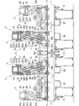
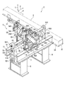
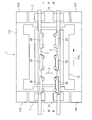
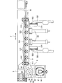
- the front view of the press machine which concerns on 1st Embodiment of this invention The front view which shows the workpiece conveyance apparatus which concerns on the said 1st Embodiment in partial cross section. The side view of the workpiece conveyance apparatus which concerns on the said 1st Embodiment. The perspective view which shows the feed drive mechanism and lift clamp drive mechanism which concern on the said 1st Embodiment. The figure which shows the motion of the transfer bar which concerns on the said 1st Embodiment.
- the perspective view which shows the lift clamp drive mechanism which concerns on the said 2nd Embodiment The perspective view which shows another state of the lift clamp drive mechanism which concerns on the said 2nd Embodiment.
- the front view of the press machine which concerns on 4th Embodiment of this invention.
- the transfer press 1 includes a press main body 11 including a bed 111, an upright 112, a crown 113, and a slide 114, a mold 12 including an upper mold 121 and a lower mold 122, and a moving bolster 13. At the same time, the transfer press 1 is provided with a transfer feeder (work transfer device) 2.
- FIG. 1 shows two uprights 112 erected on the upstream side and downstream side of the workpiece W conveyance direction (hereinafter referred to as workpiece conveyance direction) T.
- a crown 113 with a slide drive device (not shown) is supported on the upright 112, and a slide 114 that can be raised and lowered by the slide drive device is suspended from the crown 113.
- an upper mold 121 corresponding to a plurality of press forming processes is disposed along the feed direction F so as to be detachable.
- a moving bolster 13 is provided on the upper surface of the bed 111, and a lower die 122 that is paired with the plurality of upper dies 121 is detachably disposed on the upper surface of the bed 111 so as to face the upper dies 121. ing.
- the moving bolster 13 is provided so as to be able to be carried in and out of the upper surface of the bed 111 in order to replace the used mold 12 with the mold 12 to be used next by external setup.
- Rails (not shown) are laid on the floor FL and the bed 111, and the moving bolster 13 is provided with a drive device that can run on the rails.
- the moving bolster 13 passes between the illustrated uprights 112 erected along the feed direction F in the clamping direction C (see FIG. 4), and is transferred to the transfer press 1. From the outside of the transfer press 1.
- Two sets of moving bolsters 13 are usually prepared, and one set of moving bolsters 13 on which used dies 12 are placed, and the other dies 12 to be used next are mounted in advance by external setup.
- the transfer feeder 2 includes a pair of transfer bars (hereinafter referred to as bars) 3 provided on the left and right with respect to the workpiece conveyance direction T, and the bar 3 along the same feed direction F as the workpiece conveyance direction T.
- the linear motor for feed (feed drive mechanism) 4 and the bar 3 are moved back and forth in the lift direction (vertical direction perpendicular to the feed direction F and the clamp direction C) L and the clamp direction C (see FIGS. 3 and 4).
- the lift clamp drive mechanism 5 to be moved is provided.
- feed rails 34 having a length in consideration of the amount of movement in the feed direction F are provided on the side surfaces of both ends of the bar 3.
- the feed rail 34 is guided by a support portion 51.
- Such a bar 3 is provided with a workpiece holder 33 for holding the workpiece W in a detachable manner.
- the workpiece holder 33 include a finger that holds the workpiece W at the same time as a pair of bars 3 facing each other, a gripper that grips the workpiece W, a vacuum cup that sucks and holds the workpiece W, and the like. .
- the feed linear motor 4 includes a magnet plate 41 laid along the lower surface of the feed rail 34 of the bar 3, a magnet plate 41 facing the magnet plate 41, and a support member 51 with a connecting member interposed therebetween. And a coil plate 42 fixed thereto.
- the magnet plate 41 of the linear motor is provided on the bar 3 side and the coil plate 42 is provided on the support portion 51 side.
- the magnet plate 41 is provided on the support portion 51 side and the coil plate 42 is provided on the bar 3 side. May be.
- a total of four lift clamp drive mechanisms 5 are provided on the frame 7 between the two right and left uprights 112 on both sides of the workpiece conveying direction T corresponding to the fixed bars 31 at both ends of each bar 3 (see FIG. 6 and FIG. 7).
- the lift clamp drive mechanism 5 may be provided on both sides in the workpiece conveyance direction T with respect to the moving bolster 13 and may be disposed between the moving bolster 13 and the upright 112 in the workpiece conveyance direction T, for example.
- the dimension of the transfer feeder 2 in the clamping direction C can be reduced, there are fewer restrictions on the dimension in the clamping direction C than when the lift clamp drive mechanism 5 is provided between the uprights 112.
- the distance between the uprights 112 in the workpiece transfer direction T is increased, and the dimensions of the crown 113 and the bed 111 in the workpiece transfer direction T are increased. Therefore, if necessary, take measures to ensure these strengths. become.
- the lift clamp drive mechanism 5 includes a support portion 51, first and second carriers 52 and 53, first and second ball screws 54 and 55, and first and second servomotors 56. , 57, a pair of parallel links 58, a pair of drive links 59, and a pair of balancer cylinders 60, including the frame 7, and unitized as a work transfer unit.
- the support 51 includes a support main body 511 that opens upward and has a concave cross section, and an upper guide roller 512, a lower guide roller 513, and a side guide roller 514 that are provided on the support main body 511 and guide the feed rail 34. I have.
- the coil plate 42 described above is provided on the bottom surface inside the support body 511, and a pair of connection portions 514 for connecting the parallel links 58 is provided on the external bottom surface.
- the first and second carriers 52 and 53 are movably provided along the clamping direction C on the upper side of the frame 7 supported by the frame legs 8. Specifically, the first and second carriers 52, 53 have upper guide rollers 521, 531 and lower guide rollers 522, 532 that sandwich the guide rail 71 of the frame 7, and these guide rollers 521,
- the frame 7 is supported by the frame 7 so as to be movable in the clamping direction C.
- the first carrier 52 is screwed to the first ball screw 54
- the second carrier 53 is screwed to the second ball screw 55.
- one edge in the width direction of the pair of guide rails 71 is an outer guide part 72 as a first guide part parallel to the longitudinal direction of the guide rail 71, and the other edge.
- the first carrier 52 is disposed across the outer guide portion 72, and the upper guide roller 521 and the lower guide roller 522 roll along the outer guide portion 72.
- the second carrier 53 is disposed across the inner guide portion 73, and the upper guide roller 531 and the lower guide roller 532 roll along the inner guide portion 73.
- the first carrier 52 is guided by the outer guide part 72 and the second carrier 53 is guided by the inner guide part 73, so that the second carrier 53 is almost entirely inside the first carrier 52. Even when the first and second carriers 52 and 53 are most separated from each other, the partially overlapped state is maintained. As a result, the size of the clamping direction C in which the first and second carriers 52 and 53 are combined becomes compact, and the amount of movement of the second carrier 53 and thus the movement range of the transfer bar 3 in the clamping direction C are conventional. It can be secured larger than.
- the first and second ball screws 54 and 55 are provided along the clamping direction C, and are supported by the frame 7 so as to be offset from each other in the vertical direction.
- One end of each of the ball screws 54 and 55 is provided with a power transmission unit 541 and 551 that receives the rotational driving force from the first and second servomotors 56 and 57 fixed to the lower side of the frame 7.
- braking portions 542 and 552 such as electromagnetic brakes for stopping the rotation of the ball screws 54 and 55.
- the power transmission units 541 and 551 are connected to the output shafts of the first and second servo motors 56 and 57 via belts 56A and 57A, and the servo motors 56 and 57 rotate and drive the ball screws 54 and 55, respectively.
- the first carrier driving mechanism of the present invention includes a first ball screw 54 and a first servo motor 56
- the second carrier driving mechanism includes a second ball screw 55 and a second servo motor. 57.
- the parallel link 58 includes two cast links 581 and 582 arranged in parallel.
- Each of the links 581 and 582 has a structure in which a rib is erected along the longitudinal direction at the center of the flat plate portion.
- One end side of each link 581, 582 is rotatably connected to the first carrier 52, and the other end side is connected to the support portion 51 via connecting portions 583, 584, 585, 586, respectively.
- the link 581 is connected to the support part 51 and the first carrier 52 at a position higher than the connection position of the link 582 to the support part 51 and the first carrier 52.
- the connecting portion 583 is connected to the support portion 51 at a position above the connecting portion 585 on the support portion 51 side in the link 582, and the connecting portion 584 is on the first carrier 52 side in the link 582. Is connected to the first carrier 52 at a position above the connecting portion 586.
- the positions of the connecting portions 583 and 585 and the positions of the connecting portions 584 and 586 are different from each other in the vertical direction, and are not arranged in parallel to each other, so that the support body 511 that forms the support portion 51 in the clamping direction C
- the size and the size of the side portion of the first carrier 52 in the clamping direction C can be reduced. Therefore, when the first and second carriers 52 and 53 are brought close to the upright 112 side, the movement range of the transfer bar 3 in the clamping direction C is further increased.
- the drive link 59 is also plate-shaped with ribs and is made of casting. Such a drive link 59 is rotatably connected to one link of the parallel link 58 and the second carrier 53 via connecting portions 591 and 592 on both end sides. In the present embodiment, the drive link 59 is connected to the link 581 arranged at a higher position with respect to the support portion 51 and the first carrier 52.
- the support portion 51 can be moved in the lift direction according to the tilt angle of the links 581 and 582.
- the drive link 59 is connected to the link 581 arranged on the upper side of the parallel links 58, but may be connected to the lower link 582.
- the second carrier 53 is more likely to enter the first carrier 52 when the drive link 59 is connected to the link 581 disposed on the upper side. Accordingly, the size of the clamping direction C in which the first and second carriers 52 and 53 are combined can be further reduced, and the moving range can be further increased.
- the balancer cylinder 60 is provided between the second carrier 53 and the support portion 51 and connects the two.
- the balancer cylinder 60 smoothly moves the bar 3 supported by the support part 51 up and down, and the weight of the support part 51, the feed linear motor 4 and the bar 3 provided on the upper side of the balancer cylinder 60. Balance.
- FIG. 5 shows the motion of the work holder 33 according to the present embodiment.
- the basic operation pattern of the bar 3 is clamp, lift, feed, down, unclamp, and return.
- the first and second servo motors 56 and 57 are driven to move the first and second carriers 52 and 53 in the direction in which the bars 3 are separated from each other.
- the bar 3 unclamps from the clamp position to the unclamp position, and the work holder 33 retreats from the work W.
- the bar 3 is driven by the feed linear motor 4, the bar 3 returns from the first machining step position to the upstream work cradle and moves to the first work cradle.
- the conveyance and processing of the workpiece W to the next processing step are performed by transferring the workpiece W from the loading position by the transfer feeder 2 to the first processing step position of the press molding processing and forming the workpiece W in the first processing step. Done in the same way. That is, the workpiece transfer from the first machining step position to the second machining step position in the press molding process by the transfer feeder 2 and the molding process of the workpiece W in the second machining process are performed in the same manner as described above. Further, the transfer of the workpiece from the second machining step position to the third machining step position of the press molding by the transfer feeder 2 and the molding of the workpiece W in the third machining step are performed in the same manner as described above.
- the workpiece W is transferred from the most downstream machining process position of the press molding process by the transfer feeder 2. 3 is conveyed to the work receiving base at the work unloading position (bar rear end position).
- the molded workpiece W that has been carried out to the workpiece cradle at the workpiece carry-out position is carried out of the press machine by a general-purpose robot or the like.
- the lift clamp drive mechanism 5 moves the first and second carriers 52 and 53 together or independently in the clamp direction C to lift and lower the bar 3. Further, both the operation in the down direction and the operation in the clamping direction and the unclamping direction in which the bar 3 reciprocates in the direction perpendicular to the workpiece conveyance direction T are performed. Further, the feed linear motor 4 provided in the lift clamp drive mechanism 5 performs operations in the feed direction and the return direction that reciprocate the bar 3 in the workpiece conveyance direction T. Then, by reciprocating the bar 3 appropriately in the feed direction F, the lift direction L, and the clamp direction C, the workpiece W is moved from the lower mold 122 on the upstream side (left direction in FIG. 1) to the downstream side (FIG. 1). In the right direction) are sequentially transferred onto the lower mold 122.
- the transfer feeder 2 configured as described above, the following operations and effects can be obtained. That is, in the lift clamp drive mechanism, the first carrier 52 is guided by the outer guide portion 72 and the second carrier 53 is guided by the inner guide portion 73, so that the first carrier 52 is inserted into the first carrier 52 at the position where it has entered. 2 carriers 53 can be arranged, the size of the clamping direction C in which the first and second carriers 52 and 53 are combined can be made compact, and the amount of movement of the first and second carriers 52 and 53 can be increased. The moving range of the transfer bar 3 in the clamping direction C can be further increased.
- the lift drive device and the clamp drive device which have been different from each other in the past, are configured in common to form the lift clamp drive mechanism 5, only the drive pattern of the first and second carriers 52 and 53 is changed.
- the bar 3 can be lifted or clamped.
- the height of the transfer feeder 2 can be suppressed and the size can be reduced. Accordingly, not only can the degree of freedom of arrangement in the press body 11 be improved, but also the effect of facilitating the replacement of parts can be exhibited even in the case of so-called retrofit, which is being actively performed in recent years.
- the parts necessary for the lift drive and clamp drive of the bar 3 are shared, the types of parts of the transfer feeder 2 can be reduced and the structure thereof can be simplified.
- the lift clamp drive mechanism 5 is provided on each side of the workpiece transfer direction T in correspondence with the fixed bars 31 at both ends of the bar 3.
- two first and second servo motors 56 and 57 that are conventionally provided for each bar 3 for lift drive and clamp drive are provided.
- the total motor capacity for each of the lift drive and the clamp drive can be kept unchanged, and the capacity per motor can be reduced.
- the motor efficiency represented by the ratio of the peak torque of the motor to the moment of inertia of the motor decreases.
- the capacity of the first and second servomotors 56 and 57 of the lift clamp drive mechanism 5 can be reduced, so that the motor efficiency can be improved. Therefore, since the driving force of each servo motor 56, 57 can be used efficiently, the bar 3 can be lifted and clamped at higher speed.
- the support portion 51, the first and second ball screws 54 and 55, the parallel link 58, the drive link 59, and the balancer cylinder 60 are directly or indirectly connected to the first and second.
- the first and second servo motors 56 and 57 are provided on the lower side of the frame 7 and connected to the carriers 52 and 53. That is, among the elements constituting the lift clamp drive mechanism 5, the first and second servomotors 56 and 57 are provided on the lower side of the frame 7, and the other elements are provided on the upper side of the frame 7. For this reason, since it becomes unnecessary to accommodate the lift clamp drive mechanism 5 in the frame 7, the frame 7 can be made small and the weight of the frame 7 can be reduced.
- one link 581 constituting the parallel link 58 has a support portion 51 at a position higher than the connection position of the other link 582 with the support portion 51 and the first carrier 52. And connected to the first carrier 52. For this reason, the dimension between the edge parts of the clamp direction C in the parallel link 58 can be suppressed, and the dimension of the support part 51 to which the parallel link 58 is connected and the clamp direction C of the first carrier 52 can be suppressed. it can. Therefore, since the transfer feeder 2 can be reduced in size, the freedom degree of arrangement in the press body 11 can be increased.
- the feed drive mechanism of the bar 3 employs the feed linear motor 4 having no rotating parts and a small number of parts. Therefore, the feed drive mechanism can be reduced in weight and size, and the manufacturing cost of the feed drive mechanism can be reduced. Can be reduced. Moreover, since the feed linear motor 4 is small and light, chattering of the bar 3 at the time of starting, stopping, and inching can be suppressed, and the transfer feeder 2 as a whole can be increased in speed and position accuracy.
- the transfer press 1 can be operated at high speed. Furthermore, since chattering of the bar 3 is suppressed, noise during driving can be reduced, the working environment can be improved, and durability of each part of the transfer feeder 2 can be improved. As a result, the maintainability of the transfer press 1 is improved and the life of the transfer press 1 is extended.
- the upper guide rollers 521 and 531 and the lower guide rollers are provided so as to sandwich the first and second guide portions 72 and 73 of the guide rail 71 from above and below.
- side guide rollers 523 and 533 applied to the side end surface of the guide rail 71 are further provided, and the first and second carriers 52 and 53 are provided. The movement in the clamping direction C is more reliably guided.
- such side guide rollers 523 and 533 may be used in the first embodiment.
- each of the links 581 and 582 constituting the parallel link 58 has a structure in which a rib is raised along the longitudinal direction at the center of the flat plate portion.
- the links 581 and 582 of the present embodiment Is a structure in which a pair of flat plate-like portions are connected by plate-shaped ribs or cross-shaped ribs, and the rigidity is improved by increasing the thickness.
- the drive link 59 also has a structure in which ribs are provided around the plate-like portion, and the rigidity is improved. Such links 59, 581 and 582 are also cast.
- the opposing links 581 are connected to each other via a metal connecting rod 587, and the upper end side of the drive link 59 is connected to the connecting rod 587.
- a spherical bush (not shown) is accommodated in the coupling portion 591 between the drive link 59 and the coupling rod 587, and the driving link 59 and the coupling rod 587 are coupled via the spherical bush. .
- the links 581 are connected to each other by the connecting rod 587, so that the mutual rigidity between the parallel links 58 is also improved.
- the rigidity of each element is enhanced, and the guide structure is also solid, so that a larger force in the feed direction F from the feed linear motor 4 can be ensured.
- the transfer bar 3 can be moved by the feed linear motor 4 at a higher speed.
- the feed linear motor 4 is provided as the feed drive mechanism of the bar 3, and the bar 3 is reciprocated along the feed direction F by the feed linear motor 4.
- the third embodiment is different in that the bar 3 is reciprocated along the feed direction F by using a timing belt mechanism 9 as a feed drive mechanism as shown in FIG.
- the timing belt mechanism 9 is provided between the bar 3 and the support portion 51, and the whole is supported by the support portion 51.
- the timing belt mechanism 9 includes an end timing belt 91 provided between the bar 3 and the support portion 51 and having both ends fixed to the bar 3, guide pulleys 92 and 93 for guiding the timing belt 91, and a rotating shaft 94.
- a driven pulley 95 shared with the guide pulley 93, a servo motor 96, a motor shaft pulley 97 provided on the output shaft of the servo motor 96, and an endless belt 98 wound around the driven pulley 95 and the motor shaft pulley 97. It is prepared for.
- the rotational driving force of the output shaft of the servo motor 96 is transmitted to the driven pulley 95 via the motor shaft pulley 97 and the endless belt 98, and the driven pulley 95, the rotating shaft 94, And the guide pulley 93 is rotated.
- the timing belt 91 is sent along the peripheral edges of the guide pulleys 92 and 93, and the bar 3 reciprocates along the feed direction F in accordance with the rotation direction of the output shaft of the servo motor 96. To do.
- the timing belt mechanism 9 is used as the feed driving mechanism, the feed driving mechanism can be reduced in weight as compared with the case where the feed linear motor 4 is used. Therefore, the weight of the transfer feeder 2 can be reduced.
- the timing belt mechanism 9 is also suitable for high-speed driving of the bar 3, and can drive the bar 3 at a higher speed than, for example, driving the bar 3 using a ball screw. Accordingly, the transfer feeder 2 can be speeded up, and the transfer press 1 can be operated at high speed.
- the lift clamp drive mechanism 5 is suspended from the crown 113 and supports the bar 3 so as to be capable of three-dimensional operation, and the feed drive mechanism 4 It is provided between the mechanism 5.
- the first and second servo motors 56 and 57 are arranged on the upper side of the frame 7 supported by the crown 113 via the frame leg portion 8.
- the first and second carriers 52 and 53 are provided below the frame 7.
- the support 51, the first and second ball screws 54 and 55, the parallel link 58, the drive link 59, and the balancer cylinder 60 are connected to the first and second carriers 52 and 53 directly or indirectly. And provided below the frame 7.
- the transfer feeder 2 configured as described above, since the lift clamp drive mechanism 5 is located above the bar 3, the visibility of the lower side of the bar 3 is not obstructed and the visibility inside the transfer press 1 is improved. Can be improved.
- a pair of guide rails 71 are provided, the outer edges are the first guide parts 72, and the inner edges are the second guide parts 73. Only one rail may be used, and one edge along the clamping direction C may be a first guide part, and the other edge may be a second guide part.
- one link of the parallel link is connected to one end of the short connecting rod, and the drive link is connected to the other end.
- the first guide portion for the first carrier and the guide portion for the second carrier may be provided on separate guide rails. In such a configuration, the first and second carriers are brought close to each other in the feed direction, and, for example, the first and second ball screws are disposed outside the first and second carriers. As in the first embodiment, it is possible to connect the parallel link and the drive link close to each other.
- the positions of the feed drive mechanism 4 and the lift clamp drive mechanism 5 with respect to the bar 3 are unified on the upstream side and the downstream side in the workpiece conveyance direction T.
- the position is not limited to this. May be different. That is, the feed drive mechanism 4 and the lift clamp drive mechanism 5 may be provided on the lower side of the bar 3 on the upstream side in the workpiece conveyance direction T, and may be provided on the upper side of the bar 3 on the downstream side. Moreover, you may provide the feed drive mechanism 4 and the lift clamp drive mechanism 5 in the position opposite to this. Thereby, the arrangement
- the first and second carriers 52 and 53 are driven by the first and second ball screws 54 and 55 and the first and second servomotors 56 and 57.
- the linear motor may be used as in the case of the bar 3. That is, by providing a magnet plate on one of the first and second carriers 52 and 53 and the frame 7 and providing a coil plate on the other, the first and second carriers 52 and 53 are driven by a linear motor. can do.
Landscapes
- Engineering & Computer Science (AREA)
- Mechanical Engineering (AREA)
- Press Drives And Press Lines (AREA)
Abstract
Description
このワーク搬送装置は、ワーク搬送方向に平行に設けられた一対のトランスファバーを有しており、これらトランスファバーには上金型および下金型に対応した複数のワーク保持手段が着脱自在に装備されている。トランスファバーは、ワーク搬送方向と同じフィード方向に沿って往復するフィード方向およびリターン方向の動作と、リフト方向(上下方向)に沿った往復動であるリフト方向およびダウン方向の動作(昇降動)と、水平面上でフィード方向に直交するクランプ方向に往復動するクランプ方向およびアンクランプ方向の動作との3次元動作を行うことにより、ワークを上流側の金型の位置から下流側の金型の位置に順次移送している。
すなわち、クランプ方向に移動自在に設けられた第1のキャリアと、第1のキャリアとは独立してクランプ方向に移動自在に設けられた第2のキャリアと、第1のキャリアをクランプ方向に駆動する第1のキャリア駆動機構(ボールスクリューおよびこれを駆動する電動モータ)と、第2のキャリアをクランプ方向に駆動する第2のキャリア駆動機構(ボールスクリューおよびこれを駆動する電動モータ)と、第1のキャリアとトランスファバー支持用の支持部とを連結し、その連結部を中心として回動自在に設けられた平行リンクと、平行リンクの一方のリンクと第2のキャリアとを連結し、その連結部を中心として回動自在に設けられた駆動リンクとを備えた構成である。
また、特許文献2に記載のワーク搬送装置では、リフト駆動装置、クランプ駆動装置、およびフィード駆動装置は、それぞれ異なった機構で構成されている。このため、部品の種類が多く構造が複雑となり、ワーク搬送装置の製造コストが上昇してしまう。
本発明の第2の目的は、プレス本体内への配置自由度を高めることができるとともに、製造コストを低減できるプレス機械のワーク搬送装置およびワーク搬送ユニットを提供することにある。
第3発明は、前記平行リンクのうち前記駆動リンクと連結される一方のリンクでは、前記支持部に対する連結部および前記第1キャリアに対する連結部が他方のリンクよりも上側にあることを特徴とする。
第6発明では、前記駆動リンクは前記連結杆を介して前記平行リンクに連結されていることを特徴とする。
第7発明では、前記駆動リンクは球面ブッシュを介して前記連結杆に連結されていることを特徴とする。
第10発明では、前記第2のキャリアと前記支持部とを連結するバランサシリンダを備えたことを特徴とする。
さらに、少なくともリフトクランプ駆動機構を含んでユニット化しておけば、該駆動機構の一部に不具合が生じた場合、ユニット毎容易に交換でき、メンテナンス性を向上させることができる。
このため、第4発明では、第1のキャリアをより幅の広い第1のガイド部間に跨らせて荷重を支持するようにしており、支持状態を安定して維持できる。
第7発明によれば、駆動リンクは球面ブッシュを介して前記連結杆に連結されているので、運転中に平行リンクや駆動リンクに一時的な歪みが生じた場合でも、各リンクの互いのずれを球面ブッシュにて吸収でき、滑らかな動きを継続できる。
本発明では、各ボールスクリューに第1、第2のキャリア側のナットが螺合するが、各ボールスクリューが同一平面内に並設されていると、第1、第2のキャリアを互いにラップさせる位置まで近接させるためには、ナット同士の干渉を避ける必要性から各ボールスクリューをフィード方向に大きく間隔を空けて配置しなければならない。これに対して第8発明によれば、各ボールスクリューと第1、第2のキャリアとの螺合部分が同一平面にないことから、フィード方向に対して小型化できる度合いが大きい。
さらに、1本のトランスファバーを複数のリフトクランプ駆動機構で動作させるので、1つのリフトクランプ駆動機構で動作させる場合に比べ、第1および第2のキャリア駆動機構に要求される駆動出力を低減することができるとともに、第1および第2のキャリア駆動機構の駆動効率を高めることができる。従って、ワーク搬送装置を小型化でき、製造コストを一層抑制できる。
まず、図1により本発明の第1実施形態に係るトランスファプレス(プレス機械)1の全体構成を説明する。
トランスファプレス1は、ベッド111、アプライト112、クラウン113、およびスライド114を備えたプレス本体11と、上金型121および下金型122を備えた金型12と、ムービングボルスタ13とを備えているとともに、このようなトランスファプレス1にはトランスファフィーダ(ワーク搬送装置)2が設けられている。
図1において、トランスファフィーダ2は、ワーク搬送方向Tに対して左右に設けられた一対のトランスファバー(以下、バーと称する)3と、このバー3をワーク搬送方向Tと同じフィード方向Fに沿って往復移動させるフィード用リニアモータ(フィード駆動機構)4と、バー3をリフト方向(フィード方向Fおよびクランプ方向Cに直交する上下方向)Lおよびクランプ方向C(図3および図4参照)に往復移動させるリフトクランプ駆動機構5とを備えて構成されている。
なお、リニアモータのマグネット板41をバー3側に、コイル板42を支持部51側に設けた場合で説明したが、マグネット板41を支持部51側に、コイル板42をバー3側に設けてもよい。
なお、リフトクランプ駆動機構5は、ムービングボルスタ13に対してワーク搬送方向Tの両側にあればよく、例えば、ワーク搬送方向Tにおけるムービングボルスタ13およびアプライト112間に配置してもよい。この場合、トランスファフィーダ2のクランプ方向Cの寸法を小さくすることができるので、リフトクランプ駆動機構5をアプライト112間に設けるよりも、クランプ方向Cの寸法上の制約は少なくなる。一方、ワーク搬送方向Tにおけるアプライト112間の距離が長くなり、クラウン113およびベッド111のワーク搬送方向Tの寸法が大きくなるので、必要に応じて、これらの強度を確保するための対応を取ることになる。
なお、上側に配置されたリンク581に駆動リンク59を連結する方が、第1のキャリア52内に第2のキャリア53がより入り込むようになる。従って、第1、第2のキャリア52,53を合わせたクランプ方向Cの大きさをより小さくすることができ、移動範囲をさらに大きくできる。
図5には、本実施形態に係るワーク保持具33のモーションが示されている。このように、バー3の基本的な動作パターンは、クランプ、リフト、フィード、ダウン、アンクランプ、リターンである。
なお、ワーク保持具33がアンクランプ位置まで移動し、金型12との干渉域外に退避した後、スライド114の下降動作を行い、その下面に取着した上金型121を下降させて、これと下金型122との間でワークWを加圧挟持して所定の第1加工工程の成型加工を行う。
すなわち、リフトクランプ駆動機構において、第1のキャリア52は外側ガイド部72によってガイドされ、第2のキャリア53は内側ガイド部73によってガイドされるため、第1のキャリア52内に入り込んだ位置に第2のキャリア53を配置でき、第1、第2のキャリア52,53を合わせたクランプ方向Cの大きさをコンパクトにでき、第1、第2のキャリア52,53の移動量を大きくできて、トランスファバー3のクランプ方向Cの移動範囲をより大きくできる。
加えて、バー3のリフト駆動およびクランプ駆動に必要な部品を共有しているため、トランスファフィーダ2の部品の種類を少なくすることができるとともに、その構造を簡略化できる。
以下には、図8から図10に基づき、本発明の第2実施形態について説明する。
前述した第1実施形態の第1、第2のキャリア52,53では、ガイドレール71の第1、第2ガイド部72,73を上下から挟持するように上部ガイドローラ521,531および下部ガイドローラ522,532が設けられていたが、本実施形態ではさらに、ガイドレール71の側端面にあてがわれる側部ガイドローラ523,533が設けられており、第1、第2のキャリア52,53のクランプ方向Cの移動がより確実にガイドされるようになっている。なお、そのような側部ガイドローラ523,533を第1実施形態で用いても勿論よい。
次に、図11に基づき、本発明の第3実施形態について説明する。
前述した第1実施形態では、バー3のフィード駆動機構としてフィード用リニアモータ4が設けられ、このフィード用リニアモータ4により、バー3をフィード方向Fに沿って往復移動させていた。
これに対し、第3実施形態では、図11に示すように、フィード駆動機構としてタイミングベルト機構9を用いて、バー3をフィード方向Fに沿って往復移動させる点が相違する。
また、タイミングベルト機構9は、バー3の高速駆動にも適しており、例えば、ボールスクリューを用いてバー3を駆動する場合と比べて、バー3をより高速で駆動することができる。従って、トランスファフィーダ2の高速化が図れ、トランスファプレス1の高速運転が可能となる。
次に、図12に基づき、本発明の第4実施形態について説明する。
前述した第1実施形態および第2実施形態では、フィード駆動機構4およびリフトクランプ駆動機構5は、バー3の下側に設けられていた。
これに対し、第3施形態では、図12に示すように、フィード駆動機構4およびリフトクランプ駆動機構5が、バー3の上側に設けられている点が相違する。
また、図12での図示は省略するが、リフトクランプ駆動機構5において、第1および第2のサーボモータ56,57は、フレーム脚部8を介してクラウン113に支持されたフレーム7の上側に設けられ、第1および第2のキャリア52,53は、フレーム7の下側に設けられている。また、支持部51、第1および第2のボールスクリュー54,55、平行リンク58、駆動リンク59、およびバランサシリンダ60は、直接的または間接的に第1および第2のキャリア52,53に接続されて、フレーム7の下側に設けられている。
例えば、前記各実施形態では、第1、第2のガイド部72,73間に跨って配置された第1、第2のキャリア52,53には、一対の平行リンク58および一対の駆動リンク59が連結されていたが、そのような平行リンクや駆動リンクが1つだけ設けられている場合でも、本発明のリフトクランプ駆動機構に含まれる。
また、第1のキャリア用の第1のガイド部と第2のキャリア用のガイド部とをそれぞれ独立した別々のガイドレールに設けてもよい。このような構成では、第1、第2のキャリア同士をフィード方向に近接させ、例えば、第1、第2のボールスクリューなどを、第1、第2のキャリアを挟んで外側に配置することにより、第1実施形態のように、平行リンクと駆動リンクとを互いに近づけて連結させることが可能である。
また、第1および第2のサーボモータ56,57の回転力は、ベルト56A,57Aを介して第1および第2のボールスクリュー54,55に伝達されていたがこれに限られず、回転力を伝達できるものであれば、例えば、ギヤやチェーン等の他の伝達手段を用いて伝達されるようにしてもよい。
Claims (14)
- プレス機械のワーク搬送装置であって、
ワーク搬送方向に平行に配置される一対のトランスファバーと、
前記一対のトランスファバーを前記ワーク搬送方向に駆動するフィード駆動機構と、
前記一対のトランスファバーをリフト方向に駆動して上下動させるとともに、ワーク搬送方向に直交するクランプ方向に駆動するリフトクランプ駆動機構とを備え、
前記リフトクランプ駆動機構は、
前記トランスファバーを支持する支持部と、
前記クランプ方向に移動自在に設けられた第1のキャリアと、
前記第1のキャリアとは独立して前記クランプ方向に移動自在に設けられた第2のキャリアと、
前記第1のキャリアを前記クランプ方向に駆動する第1のキャリア駆動機構と、
前記第2のキャリアを前記クランプ方向に駆動する第2のキャリア駆動機構と、
前記第1のキャリアと前記支持部とを連結し、その連結部を中心として回動自在に設けられた平行リンクと、
前記平行リンクのうちの何れか一方のリンクと前記第2のキャリアとを連結し、その連結部を中心として回動自在に設けられた駆動リンクと、
前記第1のキャリアの前記クランプ方向への移動をガイドする第1のガイド部と、
前記第2のキャリアの前記クランプ方向への移動をガイドする第2のガイド部とを備え、
前記第1のガイド部および前記第2のガイド部は、互いに平行で、かつ前記ワーク搬送方向にずれている
ことを特徴とするプレス機械のワーク搬送装置。 - 請求項1に記載のプレス機械のワーク搬送装置において、
前記平行リンクの各リンクでは、前記支持部に対する連結部の上下位置が異なるとともに、前記第1のキャリアに対する連結部の上下位置が異なる
ことを特徴とするプレス機械のワーク搬送装置。 - 請求項2に記載のプレス機械のワーク搬送装置において、
前記平行リンクのうち前記駆動リンクと連結される一方のリンクでは、前記支持部に対する連結部および前記第1キャリアに対する連結部が他方のリンクよりも上側にある
ことを特徴とするプレス機械のワーク搬送装置。 - 請求項1から請求項3のいずれかに記載のプレス機械のワーク搬送装置において、
前記第1のキャリアは、互いに平行に設けられた一対の前記第1のガイド部にガイドされ、
前記第2のキャリアは、互いに平行に設けられた一対の前記第2のガイド部にガイドされ、
前記一対の第1のガイド部の内側に前記一対の第2のガイド部が位置している
ことを特徴とするプレス機械のワーク搬送装置。 - 請求項4に記載のプレス機械のワーク搬送装置において、
前記平行リンクは一対設けられ、
前記一対の平行リンク同士が連結杆により連結されている
ことを特徴とするプレス機械のワーク搬送装置。 - 請求項5に記載のプレス機械のワーク搬送装置において、
前記駆動リンクは前記連結杆を介して前記平行リンクに連結されている
ことを特徴とするプレス機械のワーク搬送装置。 - 請求項6に記載のプレス機械のワーク搬送装置において、
前記駆動リンクは球面ブッシュを介して前記連結杆に連結されている
ことを特徴とするプレス機械のワーク搬送装置。 - 請求項1から請求項7のいずれかに記載のプレス機械のワーク搬送装置において、
前記第1のキャリア駆動機構は、前記第1のキャリアと螺合する第1のボールスクリューを備え、
前記第2のキャリア駆動機構は、前記第2のキャリアと螺合する第2のボールスクリューを備え、
前記各ボールスクリューは、上下に配置されている
ことを特徴とするプレス機械のワーク搬送装置。 - 請求項1から請求項8のいずれかに記載のプレス機械のワーク搬送装置において、
前記フィード駆動機構は、前記トランスファバーと前記支持部との間に設けられている
ことを特徴とするプレス機械のワーク搬送装置。 - 請求項1から請求項9のいずれかに記載のプレス機械のワーク搬送装置において、
前記第2のキャリアと前記支持部とを連結するバランサシリンダを備えた
ことを特徴とするプレス機械のワーク搬送装置。 - 請求項1から請求項10のいずれかに記載のプレス機械のワーク搬送装置において、
ムービングボルスタの前記ワーク搬送方向両側に配置されたフレームを備え、
前記第1のキャリア駆動機構は、クランプ方向に沿って延びる第1のボールスクリューと、前記第1のボールスクリューを回転駆動する第1のサーボモータとを備え、
前記第2のキャリア駆動機構は、クランプ方向に沿って延びる第2のボールスクリューと、前記第2のボールスクリューを回転駆動する第2のサーボモータとを備え、
前記第1および前記第2のキャリア、前記支持部、前記平行リンク、および前記駆動リンクは、前記フレームの上側に設けられ、
前記第1のボールスクリューは前記第1のキャリアに螺合されて前記フレームに設けられ、
前記第2のボールスクリューは前記第2のキャリアに螺合されて前記フレームに設けられ、
前記第1および前記第2のサーボモータは、前記フレームの下側に設けられている
ことを特徴とするプレス機械のワーク搬送装置。 - 請求項1から請求項10のいずれかに記載のプレス機械のワーク搬送装置において、
ムービングボルスタの前記ワーク搬送方向両側に配置されたフレームを備え、
前記第1のキャリア駆動機構は、クランプ方向に沿って延びる第1のボールスクリューと、前記第1のボールスクリューを回転駆動する第1のサーボモータとを備え、
前記第2のキャリア駆動機構は、クランプ方向に沿って延びる第2のボールスクリューと、前記第2のボールスクリューを回転駆動する第2のサーボモータとを備え、
前記第1および前記第2のキャリア、前記支持部、前記平行リンク、および前記駆動リンクは、前記フレームの下側に設けられ、
前記第1のボールスクリューは前記第1のキャリアに螺合されて前記フレームに設けられ、
前記第2のボールスクリューは前記第2のキャリアに螺合されて前記フレームに設けられ、
前記第1および前記第2のサーボモータは、前記フレームの上側に設けられている
ことを特徴とするプレス機械のワーク搬送装置。 - 請求項1から請求項12のいずれかに記載のプレス機械のワーク搬送装置において、
前記フィード駆動機構および前記リフトクランプ駆動機構は、前記ワーク搬送方向の上流側のアプライト間および下流側のアプライト間のそれぞれに設けられている
ことを特徴とするプレス機械のワーク搬送装置。 - 請求項1から請求項13のいずれかに記載のワーク搬送装置を構成する少なくともリフトクランプ駆動機構がユニット化されている
ことを特徴とするワーク搬送ユニット。
Priority Applications (4)
| Application Number | Priority Date | Filing Date | Title |
|---|---|---|---|
| JP2011521850A JP5271413B2 (ja) | 2009-07-06 | 2010-03-29 | プレス機械のワーク搬送装置およびワーク搬送ユニット |
| DE112010002838T DE112010002838T5 (de) | 2009-07-06 | 2010-03-29 | Werküberführungsvorrichtung für Pressmaschine undWerküberführungsanlage |
| US13/382,638 US8640614B2 (en) | 2009-07-06 | 2010-03-29 | Work transfer apparatus for press machine, and work transfer unit |
| CN201080030189.9A CN102470420B (zh) | 2009-07-06 | 2010-03-29 | 压力机的工件搬送装置及工件搬送单元 |
Applications Claiming Priority (2)
| Application Number | Priority Date | Filing Date | Title |
|---|---|---|---|
| JP2009-160142 | 2009-07-06 | ||
| JP2009160142 | 2009-07-06 |
Publications (1)
| Publication Number | Publication Date |
|---|---|
| WO2011004644A1 true WO2011004644A1 (ja) | 2011-01-13 |
Family
ID=43429069
Family Applications (1)
| Application Number | Title | Priority Date | Filing Date |
|---|---|---|---|
| PCT/JP2010/055533 Ceased WO2011004644A1 (ja) | 2009-07-06 | 2010-03-29 | プレス機械のワーク搬送装置およびワーク搬送ユニット |
Country Status (5)
| Country | Link |
|---|---|
| US (1) | US8640614B2 (ja) |
| JP (1) | JP5271413B2 (ja) |
| CN (1) | CN102470420B (ja) |
| DE (1) | DE112010002838T5 (ja) |
| WO (1) | WO2011004644A1 (ja) |
Cited By (3)
| Publication number | Priority date | Publication date | Assignee | Title |
|---|---|---|---|---|
| CN103157732A (zh) * | 2011-12-08 | 2013-06-19 | 莱恩精机(深圳)有限公司 | 一种机械手 |
| CN107442685A (zh) * | 2017-07-22 | 2017-12-08 | 滁州华宇机件有限公司 | 一种空调外壳冲压结构的落料装置 |
| WO2022030111A1 (ja) * | 2020-08-06 | 2022-02-10 | コマツ産機株式会社 | ワーク搬送装置 |
Families Citing this family (10)
| Publication number | Priority date | Publication date | Assignee | Title |
|---|---|---|---|---|
| JP5599619B2 (ja) * | 2010-01-27 | 2014-10-01 | 株式会社小松製作所 | トランスファバー |
| JP2011194428A (ja) * | 2010-03-18 | 2011-10-06 | Aida Engineering Ltd | 搬送装置の破損防止機構およびそれを用いた搬送装置 |
| DE102012110065A1 (de) * | 2012-10-22 | 2014-04-24 | Schuler Automation Gmbh & Co. Kg | Umformanlage |
| JP6768454B2 (ja) * | 2016-11-08 | 2020-10-14 | コマツ産機株式会社 | ワーク搬送装置 |
| CN108746289B (zh) * | 2018-06-05 | 2024-02-09 | 奥克斯空调股份有限公司 | 一种滚筋装置以及滚筋设备 |
| JP7229105B2 (ja) * | 2019-06-11 | 2023-02-27 | 住友重機械工業株式会社 | プレス装置、プレス装置の搬送モーション設定方法及び搬送モーション設定プログラム |
| JP6626234B1 (ja) * | 2019-06-28 | 2019-12-25 | 旭精機工業株式会社 | ワーク取出装置及びトランスファプレス機 |
| JP7083322B2 (ja) * | 2019-07-17 | 2022-06-10 | アイダエンジニアリング株式会社 | トランスファープレスマシンのワーク搬送システム |
| CN112736624B (zh) * | 2020-12-23 | 2022-12-13 | 上海浦壹电子科技有限公司 | 一种芯片全自动固定装置 |
| CN115816901B (zh) * | 2023-02-08 | 2023-05-09 | 成都正西液压设备制造有限公司 | 一种用于液压机工作台的自动上下料装置及上下料方法 |
Citations (2)
| Publication number | Priority date | Publication date | Assignee | Title |
|---|---|---|---|---|
| US6073551A (en) * | 1997-05-23 | 2000-06-13 | Schuler Pressen Gmbh & Co. | Press having a transfer device for workpieces |
| JP2004243397A (ja) * | 2003-02-17 | 2004-09-02 | Ishikawajima Harima Heavy Ind Co Ltd | パネル搬送装置 |
Family Cites Families (9)
| Publication number | Priority date | Publication date | Assignee | Title |
|---|---|---|---|---|
| US3073551A (en) * | 1959-06-01 | 1963-01-15 | Wilbert C Bradshaw | Vertical lift aircraft |
| US5452981A (en) * | 1991-03-06 | 1995-09-26 | Leland D. Blatt | Automatic tool changer |
| US5632181A (en) * | 1995-02-23 | 1997-05-27 | Verson, A Division Of Allied Products Corporation | System and method for transferring a work piece in a multi-station press |
| DE19654473A1 (de) * | 1996-12-27 | 1998-07-02 | Schuler Pressen Gmbh & Co | Mehrstationenpresse |
| DE10064154B4 (de) * | 2000-12-22 | 2004-06-03 | Schuler Pressen Gmbh & Co. Kg | Mehrstufenpresse" |
| JP4300404B2 (ja) | 2003-02-17 | 2009-07-22 | 株式会社Ihi | パネル搬送装置 |
| CN100400191C (zh) * | 2003-10-14 | 2008-07-09 | 株式会社小松制作所 | 压力机械的工件输送装置 |
| JP2005153016A (ja) * | 2003-10-29 | 2005-06-16 | Komatsu Ltd | プレス機械のワーク搬送装置 |
| JP2006021235A (ja) * | 2004-07-09 | 2006-01-26 | Komatsu Ltd | プレス機械のワーク搬送装置 |
-
2010
- 2010-03-29 JP JP2011521850A patent/JP5271413B2/ja not_active Expired - Fee Related
- 2010-03-29 DE DE112010002838T patent/DE112010002838T5/de not_active Withdrawn
- 2010-03-29 WO PCT/JP2010/055533 patent/WO2011004644A1/ja not_active Ceased
- 2010-03-29 CN CN201080030189.9A patent/CN102470420B/zh not_active Expired - Fee Related
- 2010-03-29 US US13/382,638 patent/US8640614B2/en not_active Expired - Fee Related
Patent Citations (2)
| Publication number | Priority date | Publication date | Assignee | Title |
|---|---|---|---|---|
| US6073551A (en) * | 1997-05-23 | 2000-06-13 | Schuler Pressen Gmbh & Co. | Press having a transfer device for workpieces |
| JP2004243397A (ja) * | 2003-02-17 | 2004-09-02 | Ishikawajima Harima Heavy Ind Co Ltd | パネル搬送装置 |
Cited By (6)
| Publication number | Priority date | Publication date | Assignee | Title |
|---|---|---|---|---|
| CN103157732A (zh) * | 2011-12-08 | 2013-06-19 | 莱恩精机(深圳)有限公司 | 一种机械手 |
| CN103157732B (zh) * | 2011-12-08 | 2015-01-07 | 莱恩精机(深圳)有限公司 | 一种机械手 |
| CN107442685A (zh) * | 2017-07-22 | 2017-12-08 | 滁州华宇机件有限公司 | 一种空调外壳冲压结构的落料装置 |
| WO2022030111A1 (ja) * | 2020-08-06 | 2022-02-10 | コマツ産機株式会社 | ワーク搬送装置 |
| JP7489856B2 (ja) | 2020-08-06 | 2024-05-24 | コマツ産機株式会社 | ワーク搬送装置 |
| US12576444B2 (en) | 2020-08-06 | 2026-03-17 | Komatsu Industries Corporation | Workpiece transport device |
Also Published As
| Publication number | Publication date |
|---|---|
| JP5271413B2 (ja) | 2013-08-21 |
| DE112010002838T5 (de) | 2012-06-06 |
| CN102470420A (zh) | 2012-05-23 |
| JPWO2011004644A1 (ja) | 2012-12-20 |
| US8640614B2 (en) | 2014-02-04 |
| CN102470420B (zh) | 2014-05-07 |
| US20120114451A1 (en) | 2012-05-10 |
Similar Documents
| Publication | Publication Date | Title |
|---|---|---|
| JP5271413B2 (ja) | プレス機械のワーク搬送装置およびワーク搬送ユニット | |
| CN100400191C (zh) | 压力机械的工件输送装置 | |
| CN111996357A (zh) | 一种全自动的齿轮热处理生产线 | |
| US7690238B2 (en) | Work carrying device of pressing machine | |
| WO2018123260A1 (ja) | プレス装置およびプレス装置の制御方法 | |
| US7748249B2 (en) | Workpiece conveyance device for pressing machine | |
| CN100429017C (zh) | 压力机械的工件搬送装置 | |
| JP6671119B2 (ja) | ワーク搬送装置 | |
| CN115026694A (zh) | 一种高效的全自动抛光机 | |
| CN212831448U (zh) | 一种大理石板材真空吸盘传送装置 | |
| JP2005153016A (ja) | プレス機械のワーク搬送装置 | |
| CN216883881U (zh) | 一种高性能机械滑台 | |
| JP4604013B2 (ja) | プレス機械のワーク搬送装置 | |
| JP2003136163A (ja) | トランスファプレスのワーク搬送方法及びワーク搬送装置 | |
| JP4778698B2 (ja) | プレス機械のワーク搬送装置 | |
| CN111392392B (zh) | 自动化生产线 | |
| CN210392405U (zh) | 一种用于工件自动摆盘堆垛机的输送机构 | |
| CN224209610U (zh) | 一种具有换向功能的模具打磨装置 | |
| JP3902012B2 (ja) | プレスのワーク搬送装置 | |
| CN212242598U (zh) | 一种通过机械手转运的空调板烫金机 | |
| JP4781881B2 (ja) | トランスファプレスのフィードバー駆動装置 | |
| CN109051719B (zh) | 一种移送装置 | |
| CN214605917U (zh) | 一种3d打印件的光固化流水线 | |
| CN113511516B (zh) | 一种太阳能电池片输送装置 | |
| JP7489856B2 (ja) | ワーク搬送装置 |
Legal Events
| Date | Code | Title | Description |
|---|---|---|---|
| WWE | Wipo information: entry into national phase |
Ref document number: 201080030189.9 Country of ref document: CN |
|
| 121 | Ep: the epo has been informed by wipo that ep was designated in this application |
Ref document number: 10796955 Country of ref document: EP Kind code of ref document: A1 |
|
| WWE | Wipo information: entry into national phase |
Ref document number: 13382638 Country of ref document: US Ref document number: 2011521850 Country of ref document: JP Ref document number: 1120100028389 Country of ref document: DE Ref document number: 112010002838 Country of ref document: DE |
|
| 122 | Ep: pct application non-entry in european phase |
Ref document number: 10796955 Country of ref document: EP Kind code of ref document: A1 |