WO2010150306A1 - 圧入治具、圧入装置及び圧入方法 - Google Patents
圧入治具、圧入装置及び圧入方法 Download PDFInfo
- Publication number
- WO2010150306A1 WO2010150306A1 PCT/JP2009/002850 JP2009002850W WO2010150306A1 WO 2010150306 A1 WO2010150306 A1 WO 2010150306A1 JP 2009002850 W JP2009002850 W JP 2009002850W WO 2010150306 A1 WO2010150306 A1 WO 2010150306A1
- Authority
- WO
- WIPO (PCT)
- Prior art keywords
- press
- fitting
- workpiece
- hole
- reaction force
- Prior art date
- Legal status (The legal status is an assumption and is not a legal conclusion. Google has not performed a legal analysis and makes no representation as to the accuracy of the status listed.)
- Ceased
Links
Images





Classifications
-
- B—PERFORMING OPERATIONS; TRANSPORTING
- B23—MACHINE TOOLS; METAL-WORKING NOT OTHERWISE PROVIDED FOR
- B23P—METAL-WORKING NOT OTHERWISE PROVIDED FOR; COMBINED OPERATIONS; UNIVERSAL MACHINE TOOLS
- B23P19/00—Machines for simply fitting together or separating metal parts or objects, or metal and non-metal parts, whether or not involving some deformation; Tools or devices therefor so far as not provided for in other classes
- B23P19/02—Machines for simply fitting together or separating metal parts or objects, or metal and non-metal parts, whether or not involving some deformation; Tools or devices therefor so far as not provided for in other classes for connecting objects by press fit or for detaching same
Definitions
- the present invention relates to a technique for press-fitting parts into a workpiece.
- the press-fitting device usually includes a press-fitting actuator and a member that receives a press-fitting reaction force in contact with the workpiece.
- Patent Document 1 discloses an apparatus that includes a press-fit cylinder and a reaction force receiving bracket and press-fits a part into a workpiece in a horizontal direction.
- Patent Document 2 discloses an apparatus that includes a press-fitting machine and a support base body and press-fits a part into a workpiece in a vertical direction.
- Patent Document 1 discloses an apparatus that changes the posture of a workpiece so that a press-fitting point faces a vertical direction by providing a tilt mechanism on the support base body to change the tilt of the support base body.
- the apparatus may be complicated. Further, as in the apparatus described in Patent Document 1, it cannot be applied to a configuration in which a press-fit actuator and a member that contacts a work and receives a press-fit reaction force are supported by a frame and can be moved.
- An object of the present invention is to stably receive the press-fitting reaction force with a simpler configuration regardless of the shape of the workpiece.
- a press-fitting jig used in a press-fitting device comprising press-fitting means for press-fitting a part into a workpiece, and a reaction force receiving member that is disposed opposite to the press-fitting means and receives a press-fitting reaction force.
- a main body having a positioning unit that is mounted on the workpiece and that determines a mounting position on the workpiece, and a contact surface on which the reaction force receiving member abuts and is supported by the main body
- a press-fitting jig characterized in that the abutment surface is formed orthogonal to a press-fitting direction of a hole provided in the workpiece into which the part is press-fitted.
- a press-fitting unit that press-fits a part into a work
- a press-fitting unit that is disposed to face the press-fitting means and receives a press-fitting reaction force
- a press-fitting unit that is attached to the work
- a contact portion supported by the main body, and the contact surface is formed orthogonal to a press-fitting direction of a hole provided in the workpiece into which the component is press-fitted.
- a featured press fit device is provided.
- the mounting step of mounting the press-fitting jig on the work, the press-fitting means for press-fitting parts into the work, and the press-fitting means are arranged so as to face the press-fitting process through the press-fitting jig.
- a press-fitting step of press-fitting the component into the workpiece by a press-fitting device including a reaction force receiving member that receives a force, and the press-fitting jig includes a main body portion mounted on the workpiece, and the reaction force receiver. A contact portion that contacts the member, and is provided with a contact portion supported by the main body portion; and a positioning unit that is provided on the main body portion and positions the contact portion with respect to the workpiece.
- a contact surface is formed perpendicular to a press-fitting direction of a hole provided in the workpiece, into which the component is press-fitted, and in the press-fitting step, the reaction force receiving member is brought into contact with the contact surface.
- a featured press-fitting method is provided.
- the press-fitting reaction force can be stably received with a simpler configuration regardless of the shape of the workpiece.
- FIG. 1 is a perspective view of a press-fitting device A according to an embodiment of the present invention. It is explanatory drawing of the table unit 6.
- FIG. 3 is an exploded perspective view of the press-fitting unit 30 and a moving member 40.
- FIG. 3 is an exploded perspective view of the press-fitting unit 30.
- FIG. 4 is an explanatory diagram of a press-fitting operation by a press-fitting cylinder 34.
- FIG. 4 is an explanatory diagram of a press-fitting operation by a press-fitting cylinder 31.
- FIG. 3 is a perspective view of a release unit 50.
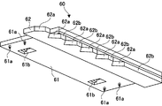
- FIG. 3 is a perspective view of a press-fitting jig 60.
- FIG. 3 is a perspective view of a press-fitting jig 60.
- FIG. 3 is a perspective view of a press-fitting jig 60.
- FIG. 1 is a perspective view of a press-fitting device A according to an embodiment of the present invention.
- an arrow Z in the figure indicates a vertical direction
- arrows X and Y indicate horizontal directions orthogonal to each other.
- the press-fitting device A includes a rectangular base board 1 and struts 2 erected at four corners of the base board 1.
- a moving device that moves the press-fitting unit 30 is supported on the support column 2.
- the moving device includes a pair of guide frames 3, a guide frame 4, a moving member 40, and driving devices 10 and 20.
- the both ends of the guide frame 3 are supported by the support 2.
- the pair of guide frames 3 are provided parallel to each other in the X direction, and each guide frame 3 extends in the Y direction.
- Each guide frame 3 is a rail member in which a guide groove 3a extending in the Y direction is formed on the upper surface thereof.
- the guide frame 3 may be configured by fixing a rail member having the guide groove 3a to a main body frame without the guide groove 3a.
- the guide frame 4 is constructed on the pair of guide frames 3 and extends in the X direction. Slide portions (not shown) that slide along the guide grooves 3a are provided at both ends of the guide frame 4, and the guide frames 4 are guided by the guide grooves 3a of the pair of guide frames 3 so that the guide frames 4 3 in the Y direction.
- the guide frame 4 is a rail member in which a guide groove 4a extending in the X direction is formed on the upper surface, and a guide groove 4b extending in the X direction is formed on the back surface. As will be described later, the moving member 40 is guided in the guide grooves 4a and 4b and is movable in the Y direction along the guide frame 4.
- the press-fitting unit 30 is connected to and fixed to the lower portion of the moving member 40. Yes.
- the guide frame 4 is a rail member in which a guide groove 4a extending in the X direction is formed on the upper surface, and a guide groove 4b extending in the X direction is formed on the back surface.
- the guide frame 4 may be configured by fixing a rail member having the guide groove 4a and a rail member having the guide groove 4b to a main body frame without the guide grooves 4a and 4b.
- the moving member 40 is guided in the guide grooves 4a and 4b and is movable in the X direction along the guide frame 4, and the press-fitting unit 30 is connected and fixed to the lower portion of the moving member 40. Yes.
- the driving device 10 includes a motor 11 and a ball screw 12 that is rotationally driven by the motor 11.
- the ball screw 12 is rotatably supported by the guide frame 3 via a support member 13.
- a ball nut 14 that is screwed into the ball screw 12 is provided at the end of the guide frame 4.
- the drive device 10 is provided on one of the pair of guide frames 3, but the drive device 10 may be provided on both of them to drive them synchronously.
- the driving device 20 includes a motor 21 and a ball screw 22 that is rotationally driven by the motor 21.
- the ball screw 22 is rotatably supported by the guide frame 4 via a support member 23.
- the moving member 40 is provided with a ball nut 24 that is screwed into the ball screw 22. When the ball screw 22 is driven to rotate by driving the motor 21, the moving member 40 moves in the X direction.
- the guide frame 4 is moved in the Y direction by the driving device 10 and the moving member 40 is moved in the X direction by the driving device 20, whereby the press-fitting unit 30 fixed to the moving member 40 is moved to the XY direction. It can move on a plane.
- a moving device that moves the press-fit unit 30, for example, an articulated robot or the like can also be employed.
- the range of movement of the press-fit unit 30 can be made larger, and the work space under the press-fit unit 30 can be made larger.
- the press-fit unit 30 is moved on the XY plane, but may be further moved in the Z direction.
- the ball screw mechanism was employ
- the press-fitting device A includes a transport device 5 for transporting the workpiece.
- the transport device 5 includes a pair of transport units 5a.
- the pair of transport units 5a is provided in parallel with being spaced apart from each other in the X direction, and each transport unit 5a is a roller conveyor unit having a roller row in the Y direction.
- the work is placed across the pair of transport portions 5a and is transported by rotationally driving the rollers in the roller array.
- a roller conveyor is employed, but other known transport mechanisms that exhibit the same operational effects may be employed.
- the conveying device 5 is arranged so as to cross the base board 1 in the Y direction, conveys a workpiece to the press-fitting device A, and is continuously arranged with another conveying device 5 ′ that conveys the workpiece from the press-fitting device A. Has been.
- the conveying device 5 By continuously transporting a plurality of workpieces by the transport device 5 ′ and the transport device 5, it is possible to sequentially perform the press-fitting work of the parts to the plurality of workpieces.
- a table unit is arranged between the transport sections 5a as shown in FIG. FIG. 2 is an explanatory diagram of the table unit 6.
- the table unit 6 includes a table 6a on which a work is placed and a drive unit 6b.
- the drive part 6b is provided with the raising / lowering mechanism which raises / lowers the table 6a, and the rotation mechanism which rotates the table 6a around a Z-axis. Any of these mechanisms can be a known mechanism.
- the table 6a is moved up and down between a press-fitting work standby position below the transport surface of the transport unit 5a and a press-fitting work position above the transport surface of the transport unit 5a by the lifting / lowering function of the drive unit 6b.
- the table 6a is initially located at the press-fitting work standby position, and the work is transported to the upper side by the transport device 5. Thereafter, the table 6a is raised by the drive unit 6b, and the workpiece is placed on the table 6a and transferred, and the table 6a is raised to the press-fitting work position.
- the press-fitting unit 30 performs press-fitting work on the work on the table 6a at the press-fitting work position.
- the table 6a is lowered to the press-fitting work standby position by the driving unit 6b, and the work is transferred from the table 6a to the transport device 5 in the middle of the lowering. Thereby, press-fitting work can be sequentially performed on a plurality of workpieces conveyed by the conveying device 5.
- a table 6a indicated by a solid line indicates the table 6a located at the press-fitting work standby position. Further, the table 6a indicated by a broken line is located at the press-fitting work position and shows a different posture (rotated 90 degrees) from the table 6a indicated by a solid line.
- a support base 8 is provided on the base board 1.
- a release unit 50 described later is mounted on the support base 8.
- a support base 9 is also mounted on the support base 8.
- a press-fitting jig 60 described later is placed on the support base 9.
- a plurality of types of press-fitting jigs 60 corresponding to the type of workpiece can be placed on the support base 9.
- a component supply device 7 is also provided on the base board 1.
- the component supply device 7 includes a supply unit 7 a and supplies components to be pressed into the workpiece one by one to the press-fitting unit 30.
- a known device can be applied to the component supply device 7.
- FIGS. 3 and 4 are exploded perspective views of the press-fit unit 30 and the moving member 40
- FIG. 4 is an exploded perspective view of the press-fit unit 30 (particularly the reaction force receiving unit 32).
- the press-fit unit 30 includes a press-fit cylinder 31, a reaction force receiving unit 32, and a frame 33 that supports them.
- the press-fit cylinder 31 includes a cylinder portion 31a fixed to one end of a frame 33 (side plate members 33e and 33e described later), and a rod portion 31b that moves forward and backward freely from the cylinder portion 31a.
- the full length of the press-fit cylinder 31 expands / contracts due to advance / retreat with respect to the cylinder portion 31a.
- a part that is press-fitted into the work is mounted on the tip of the rod part 31b, and the part is press-fitted into the work as the rod part 31b advances from the cylinder part 31a.
- the forward / backward direction of the rod portion 31b, that is, the press-fitting direction is the horizontal direction (X direction) in the present embodiment.
- the press-fit cylinder 31 may be any of a hydraulic type, a pneumatic type, and an electric type, and a press-fit actuator other than the press-fit cylinder can be employed.
- the reaction force receiving unit 32 includes a reaction force receiving member 321 that is disposed to face the tip of the rod portion 31b of the press-fitting unit 30 and receives a press-fitting reaction force.
- the reaction force receiving member 321 is supported at the other end of the frame 33 so as to be movable in the press-fitting direction by the press-fitting cylinder 31. The moving structure will be described later.
- the reaction force receiving member 321 is disposed to face the rod portion 31b and has a contact surface 321a that contacts the workpiece.
- the contact surface 321a is a surface orthogonal to the axis of the rod portion 31b (that is, the press-fitting direction line).
- the workpiece is disposed between the tip of the rod portion 31b and the abutting surface 321a.
- the frame 33 includes a pair of side plate members 33e and 33e facing each other, and upper plate members 33d and 33d and a lower plate member 33b disposed between the side plate members 33e and 33e.
- the upper plate members 33d and 33d are spaced apart in the press-fitting direction, and an opening 33a through which the rod part 34b of the press-fitting cylinder 34 can pass is formed therebetween.
- the press-fit cylinder 34 has the same configuration as the press-fit cylinder 31 and includes a cylinder part 34a and a rod part 34b that moves forward and backward freely from the cylinder part 34a.
- the press-fit cylinder 34 the forward / backward direction of the rod portion 34b, that is, the press-fit direction is a vertical direction (Z direction), and the table 6a is used as a reaction force receiving member, and components are mounted on the tip of the rod portion 34b. Then, the part is press-fitted into the workpiece.
- the press-fit cylinder 34 may be any of a hydraulic type, a pneumatic type, and an electric type, and a press-fit actuator other than the press-fit cylinder can be employed.
- the press-fit cylinder 34 is supported by the cylinder portion 34 a being fixed to the back side (the ⁇ Y direction in FIG. 3) of the main body portion 41 of the support member 40, but is fixed to the frame 33. It is good also as a structure supported by.
- FIG. 5 is an explanatory diagram of the press-fitting operation in the vertical direction by the press-fitting cylinder 34.
- the rod portion 34b is moved downward to enter a press-fit hole (not shown) formed on the upper surface of the workpiece W on the table 6a.
- the part P can be press-fitted.
- the table 6 a (table unit 6) receives the press-fitting reaction force of the press-fitting cylinder 34.
- FIG. 6 is an explanatory diagram of a horizontal press-fitting operation by the press-fitting cylinder 31.
- a press-fitting hole (not shown) formed on the side surface of the workpiece W on the table 6a by advancing the rod portion 31b in the X direction with the component P attached to the tip of the rod portion 31b.
- the part P can be press-fitted into.
- the reaction force receiving member 321 receives the press-fitting reaction force.
- the press-fitting operation can be continuously performed on the side surface and the upper surface of the workpiece.
- the moving member 40 includes a main body portion 41 having a U-shaped cross section, and engages with the guide groove 4 a on the front side (the side opposite to the side protruding in the U shape).
- a roof portion 42 from which the slide portion 42a protrudes downward, a slide portion 43 that engages with the guide groove 4b, and a ball nut 24 that is screwed into the ball screw 22 are provided.
- the moving member 40 is supported by the guide frame 4 by the slide portion 42 a and the slide portion 43.
- the upper surface of the frame 33 is fixed to the bottom surface of the moving member 40 (main body portion 41).
- the fixing means may be either welding or bolt fastening.
- Each side plate member 33e of the frame 33 is provided with a mounting unit 70 that holds the press-fitting jig 60 and mounts it on a workpiece. Details will be described later.
- the frame 33 includes a lower plate member 33b on the bottom side of the other end portion, and a pair of rail portions 33c extending in the press-fitting direction of the press-fitting cylinder 31 is fixed to the lower surface of the lower plate member 33b with a space therebetween.
- a slide portion 323 is engaged with each rail portion 33 c, and a support plate 322 is fixed to both slide portions 323.
- the reaction force receiving member 321 described above is fixed to the support plate 322. With these configurations, the reaction force receiving member 321 can slide along the rail portion 33 c, that is, can move in the press-fitting direction of the press-fitting cylinder 31.
- the press-fit unit 30 is provided with a restriction mechanism 80 that restricts the movement of the reaction force receiving member 321 so that the restriction can be released.
- the restriction mechanism 80 is attached to the plurality of engaged portions 81 provided on the lower plate member 33b along the longitudinal direction of the rail portion 33c and the support plate 322, and any of the engaged portions is engaged. And an engaging portion 82 that engages with the portion 81.
- the engaged portion 81 is a hole that penetrates the lower plate member 33b.
- the engaging portion 82 is a rod member whose front end portion faces between the rail portions 33c and 33c. The other end of the rod member 82 is inserted into a hole 322 a that penetrates the support plate 322, and is fixed to a knob (knob member) 83 on the lower surface side of the support plate 322.
- a flange 82 a is formed in the middle of the rod member 82, and an urging member 84 is mounted between the flange 82 a and the support plate 322.
- the urging member 84 is a coil spring, and the urging member 84 constantly urges the rod member 82 in the direction in which it is inserted into the hole 81, that is, in the upward direction.
- the restriction mechanism 80 having such a configuration is engaged with the lower plate member 33b by inserting the upper end of the rod member 82 into the hole 81, and restricts the movement of the reaction force receiving member 321. Moreover, the movement restriction
- interposed between the rod part 31b and the reaction force receiving member 321 improves, and it can respond to a wider range with respect to the workpiece
- the plurality of holes 81 and the rod member 82 are employed as the restriction mechanism 80 as described above.
- the configuration of such engaged portions and engaging portions that are engaged with each other has various structures. Can be adopted.
- the rod member 82 (engagement portion) is urged by the urging member 84 toward the hole 81 (engaged portion).
- the present invention is not limited to this.
- the engaged portion may be urged by the urging member 84 toward the portion. That is, any one or both of the engaged portion and the engaging portion may be configured to be urged by the urging member 84 in the direction in which both are engaged.
- FIG. 7 is a perspective view of the release unit 50.
- the release unit 50 holds the knob 83 of the restriction mechanism 80, pulls down the rod member 82, and releases the engagement between the rod member 82 and the hole 81.
- the release unit 50 includes an L-shaped support member 51, an air cylinder 53, a holding plate 52, a rail member 54, and a guide member 55.
- the air cylinder 53 includes a cylinder portion 53a fixed to the support member 51, and a rod portion 53b that moves forward and backward from the cylinder portion 53a.
- the forward / backward direction of the rod portion 53b with respect to the cylinder portion 53a is the vertical direction (Z direction).
- One end of the holding plate 52 is fixed to the upper end of the rod portion 53b, and the holding plate 52 is moved up and down by advancing and retracting the rod portion 53b with respect to the cylinder portion 53a.
- an air cylinder is employed as a device for moving the holding plate 52, but other actuators may be employed.
- the holding plate 52 includes a C-shaped holding portion 52a.
- the knob 83 has a relatively small diameter in the middle (see FIG. 4), and the C-shaped opening of the holding portion 52a is inserted into the small diameter portion so that the holding plate 52 and the knob 83 are engaged.
- the support member 51 is provided with a guide member 55 adjacent to the cylinder portion 53a. At least one guide member 55, preferably two or more guide members 55 are arranged in the vertical direction.
- a rail member 54 is provided on the guide member 55 so as to be movable in the vertical direction.
- a holding plate 52 is connected and fixed to the rail member 54. Accordingly, the holding plate 52 moves up and down by the advance and retreat of the rod portion 53b with respect to the cylinder portion 53a, and the rail member 54 and the guide member 55 guide the up-and-down movement of the holding plate 52.
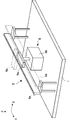
- the press-fitting jig 60 is used when there is no suitable surface (press-fitting receiving surface) on which the contact surface 321a of the reaction force receiving member 321 is in contact with the workpiece in the press-fitting work onto the workpiece by the press-fitting cylinder 31.
- it is used when a press-fitting operation is performed on a work that does not have a surface orthogonal to the press-fitting direction line on the press-fitting direction line at the press-fitting location (hole WH) of the work.
- FIG. 8 and 9 are perspective views of the press-fitting jig 60.
- FIG. 8 and 9 are perspective views of the press-fitting jig 60.
- the press-fitting jig 60 includes a main body portion 61 attached to the workpiece W and an abutting portion 62 supported by an end portion of the main body portion 61.
- the main body 61 includes a plurality of positioning pins 61 a that determine the mounting position of the press-fitting jig 60 with respect to the workpiece W.
- the positioning pin 61a protrudes from the lower surface of the main body 61 and is inserted into a hole WH formed in the workpiece W, whereby the press-fitting jig 60 can be fixedly attached to the workpiece W, and The position of the press-fitting jig 60 is determined.
- the hole WH may be a hole originally provided in the workpiece W, or may be formed as a dedicated hole for inserting the positioning pin 61a.
- the positioning pin 61a and the hole WH are used to determine the mounting position of the press-fitting jig 60 on the workpiece W.
- the present invention is not limited to this, and various positioning structures can be used.
- the main body 61 has a rectangular plate shape, and a plurality of engaging portions 61b each having an opening are formed.
- the engaging portion 61b is for inserting claw members 75 and 76 (described later) of the mounting unit 70 to engage the front end portion of the claw member, and its inner wall has a stepped shape as indicated by a broken line. Yes.
- the contact portion 62 includes a first contact surface 62a with which the contact surface 321a of the reaction force receiving member 321 contacts, and a second contact surface 62b.
- the first contact surface 62a and the second contact surface 62b have mutually different surface angles.
- the first contact surface 62a is formed perpendicular to the press-fitting direction of the first press-fitting hole Wa provided in the workpiece W.
- the second contact surface 62b is formed orthogonal to the press-fitting direction of the second press-fitting hole Wb having a different press-fitting direction from the first press-fitting hole Wa.
- the contact portion 62 may be formed integrally with the main body portion 61 or may be attached so as to be separable. When it is configured to be separably attached, a plurality of types of contact portions 62 having different contact surface orientations depending on the press-fitting direction are selectively attached to the main body portion 61. Compatible with multiple types of press-fitting directions.
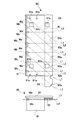
- FIG. 10 is a plan view and a front view of the press-fitting jig 60 attached to the workpiece W.
- the first press-fitting hole Wa is formed on one side surface of the workpiece W, and is a first target portion into which a part is press-fitted.
- Line L1 indicates the center line of the first press-fitting hole Wa, that is, the press-fitting direction.
- a plurality of first press-fit holes Wa whose lines L1 are parallel to each other are formed in a line.
- the other side surface is located on the line L1 and does not have a surface orthogonal to the line L1.
- the first contact surface 62a of the press-fitting jig 60 is used as a surface orthogonal to the line L1. Due to the positional relationship with respect to the positioning pin 61a, the first contact surface 62a is designed to be positioned on the line L1 and orthogonal to the line L1 when the press-fitting jig 60 is mounted on the workpiece W.
- the second press-fitting hole Wb is formed on one side surface of the workpiece W and is a second target portion into which a part is press-fitted.
- Line L2 indicates the center line of the second press-fitting hole Wb, that is, the press-fitting direction.
- the line L2 is not parallel to the line L1 (in the direction of about 45 degrees with respect to the line L1 in plan view), and the second press-fitting hole Wb is different from the first press-fitting hole Wa.
- a plurality of second press-fit holes Wb whose lines L2 are parallel to each other are formed in a row at a predetermined interval between the first press-fit holes Wa (or in the vicinity of the first press-fit holes Wa). .
- the other side surface may be uneven, and there may be no surface that is located on the line L2 and orthogonal to the line L2. Therefore, in this case, the second contact surface 62b of the press-fitting jig 60 is used as a surface orthogonal to the line L2.
- the second contact surface 62b is designed so as to be positioned on the line L2 and orthogonal to the line L2 when the press-fitting jig 60 is mounted on the workpiece W due to the positional relationship with the positioning pin 61a.
- the first contact surface 62a corresponds to each first press-fit hole Wa.
- the second contact surface 62b is provided corresponding to each second press-fitting hole Wb, and the first contact surface 62a and the second contact surface 62b as a whole are formed in a meandering shape. Yes.
- the press-fitting jig 60 having such a configuration is mounted on the upper surface side of the work W as shown in FIG. 10 with respect to the work W placed on the table 6a at the press-fitting work position. Then, the table 6a is rotated and moved up and down by the drive unit 6b shown in FIG. 2, and the press-fitting direction of the press-fitting cylinder 31 is parallel to the line L1 direction or the line L2 direction depending on the target press-fitting holes Wa and Wb.
- the posture of the table 6a is changed so that Then, the press-fitting unit 30 is moved to the respective press-fitting positions, and the press-fitting cylinder 31 and the reaction force receiving member 321 are aligned with any of the first press-fitting holes Wa and the first contact surfaces 62a, or either The second press-fitting hole Wb and the second contact surface 62b are aligned to perform press-fitting work.
- the reaction force receiving member 321 receives the press-fitting reaction force of the press-fitting cylinder 31 by the contact surface 321a coming into contact with the first contact surface 62a or the second contact surface 62b.
- the press-fitting reaction force of the press-fitting cylinder 31 can be stably received regardless of the shape of the workpiece W with a simpler configuration, and the press-fitting operation is performed. be able to.
- the mounting unit 70 includes a support member 71 fixed to the side plate member 33 e and an air cylinder 72 supported by the support member 71.
- the air cylinder 72 extends and contracts in the vertical direction (Z direction).
- the rod portion of the air cylinder 72 is connected to a lifting plate 73 that moves up and down by the expansion and contraction of the air cylinder 72.
- An air cylinder 74 and a claw member 76 are fixed to the elevating plate 73.
- the air cylinder 74 extends and contracts in the horizontal direction (X direction) opposite to the claw member 76.
- a claw member 75 is supported on the rod portion of the air cylinder 74.
- the claw member 75 is moved by the expansion / contraction operation of the air cylinder 74, and the distance between the claw member 75 and the claw member 76 is changed (the claw tip is opened and closed).
- claw members 75 and 76 have tips (claw tips) bent outward in the X direction and engaged with the opening 61b of the main body 61 of the press-fitting jig 60 shown in FIG. Then, by opening and closing the claw member 75 and the claw member 76, the opening 61b is engaged and disengaged.
- the mounting unit 70 is formed on each side plate member 33e, and a total of four claw members 75 and 76 are engaged with the four openings 61b of the main body 61 of the press-fitting jig 60, respectively.
- the press-fitting jig 60 is held.
- the press-fitting jig 60 is placed on the support base 9 shown in FIG. 1.
- the press-fitting unit 30 is moved onto the support base 9 and the press-fitting jig 70 is used.
- the press-fitting jig 60 is mounted on the workpiece W on the table 6a.
- the mounting unit 70 by attaching or removing the press-fitting jig 60 to or from the workpiece W by the mounting unit 70, the press-fitting work using the press-fitting jig 60 and the press-fitting work without using the press-fitting jig 60 can be performed continuously.
- the configuration of the mounting unit 70 is not limited to this, and any configuration may be used as long as the press-fitting jig 60 can be held.
- FIG. 11 shows a basic operation of performing a component press-fitting work on the workpiece W that has been conveyed.
- S1 shows a state in which the workpiece W has been transferred onto the transfer device 5 from the outside of the press-fitting device A.
- the workpiece W is transferred onto the table 6a at the press-fitting work standby position (S2).
- the conveyance position of the workpiece W can be detected by various sensors.
- the table 6a is raised toward the press-fitting work position, and the workpiece W is transferred onto the table 6a.
- the press-fit unit 30 is moved onto the component supply device 7, and the parts to be press-fitted into the work W are supplied to the press-fit unit 30.
- the movement position of the press-fit unit 30 can be detected by various sensors.
- the components When components are press-fitted onto the upper surface of the workpiece W, the components are mounted on the tip of the rod portion 34 b of the press-fitting cylinder 34 by the component supply device 7. When components are press-fitted into the side surface of the workpiece W, the components are mounted on the tip of the rod portion 31 b of the press-fitting cylinder 31 by the component supply device 7.
- the press-fitting unit 30 is moved onto the workpiece W (S4), and press-fitting work is performed by the press-fitting cylinder 31 or the press-fitting cylinder 34.
- the processes of S3 and S4 are repeated as many times as the number of press-fitting locations.
- the table 6a is lowered toward the press-fitting operation standby position, and the workpiece W on the table 6a is transferred to the transfer device 5.
- the conveying device 5 conveys the workpiece W to the outside of the press-fitting device A and waits for the arrival of the next workpiece W.
- the holding plate 52 is lowered to release the engagement between the rod member 82 and the hole 81 (S22).
- the press-fitting unit 30 is moved in the X direction (press-fitting direction: left direction in FIG. 3), and another hole 81 newly engaged with the rod member 82 is aligned with the rod member 82 (S23). ).
- the holding plate 52 of the release unit 50 is raised again, and the rod member 82 and the new hole 81 are engaged.
- the press-fitting unit 30 is moved, the holding portion 52a is detached from the knob 83, and the change of the position of the reaction force receiving member 321 is completed.
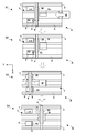
- FIG. 14 shows the operation when the press-fitting jig 60 is transported from the support base 9 onto the workpiece W and mounted on the workpiece W.
- the press-fitting jig 60 to be mounted on the work W is placed on the support base 9.
- the press-fitting unit 30 is moved onto the press-fitting jig 60, and the mounting unit 70 and the press-fitting jig 60 are aligned (S32). These alignments can be performed by detecting each other's position with various sensors. Thereafter, the claw members 75 and 76 are closed (released) by the air cylinder 74, and the elevating plate 73 is lowered by the air cylinder 72.
- the claw members 75 and 76 enter the opening 61 b of the press-fitting jig 60. Subsequently, the claw members 75 and 76 are opened (held) by the air cylinder 74, the claw members 75 and 76 are engaged with the opening 61b of the press-fitting jig 60, and the lifting plate 73 is raised by the air cylinder 72. Let As a result, the press-fitting jig 60 is held by the mounting unit 70 and lifted from the support base 9.
- the press-fitting unit 30 is moved onto the work W, and the work W and the press-fitting jig 60 are aligned (positioning of the hole WH and the positioning pin 61a) (S33). These alignments can be performed by detecting each other's position with various sensors. Thereafter, the lifting plate 73 is lowered by the air cylinder 72, and the press-fitting jig 60 is attached to the workpiece W. The claw members 75 and 76 are closed (released) by the air cylinder 74, and the elevating plate 73 is raised by the air cylinder 72. Thereby, the claw members 75 and 76 are detached from the opening 61 b of the press-fitting jig 60. Thereby, the mounting of the press-fitting jig 60 on the workpiece W is completed (S34).
Landscapes
- Engineering & Computer Science (AREA)
- Mechanical Engineering (AREA)
- Automatic Assembly (AREA)
Abstract
本発明は、部品をワークに圧入する圧入手段と、前記圧入手段と対向して配置され、圧入反力を受ける反力受け部材と、を備えた圧入装置に使用される圧入治具を提供する。この圧入治具は、前記ワークに装着され、かつ、前記ワークに対する装着位置を決める位置決め手段を有する本体部と、前記反力受け部材が当接する当接面を有し、前記本体部に支持された当接部と、を備える。前記当接面が、前記部品が圧入される、前記ワークに設けられた穴の圧入方向と直交して形成されている。
Description
本発明は、部品をワークに圧入する技術に関する。
圧入装置では、通常、圧入アクチュエータと、ワークに当接して圧入反力を受ける部材と、を備えている。例えば、特許文献1には、圧入シリンダと反力受け金具とを備え、部品をワークに水平方向に圧入する装置が開示されている。また、特許文献2には、圧入機と支持台本体とを備え、部品をワークに鉛直方向に圧入する装置が開示されている。
圧入反力を安定して受け止めるためには、圧入反力を受ける部材を当接する、適当な面がワークに圧入する側と反対側に存在している必要がある。しかし、ワークによってはそのような面(圧入反力を受ける部材を当接する適切な面)が存在しない場合がある。例えば、特許文献1の装置では、圧入方向に直交した面に反力受け金具を当接しているが、このような面がワークに存在しない場合もある。特許文献2には、支持台本体にチルト機構を設けて支持台本体の傾きを変化させることで、圧入箇所が鉛直方向を向くようにワークの姿勢を変化させる装置が開示されている。しかし、このようなワークの姿勢を変化させる機構を設けると、装置が複雑化する場合がある。また、特許文献1に記載の装置のように、圧入アクチュエータと、ワークに当接して圧入反力を受ける部材とをフレームで支持して移動可能とする構成には適用できない。
本発明の目的は、より簡易な構成で、ワークの形状に関わらず圧入反力を安定して受け止めることにある。
本発明によれば、部品をワークに圧入する圧入手段と、前記圧入手段と対向して配置され、圧入反力を受ける反力受け部材と、を備えた圧入装置に使用される圧入治具であって、前記ワークに装着され、かつ、前記ワークに対する装着位置を決める位置決め手段を有する本体部と、前記反力受け部材が当接する当接面を有し、前記本体部に支持された当接部と、を備え、前記当接面が、前記部品が圧入される、前記ワークに設けられた穴の圧入方向と直交して形成されていることを特徴とする圧入治具が提供される。
また、本発明によれば、部品をワークに圧入する圧入手段、及び、前記圧入手段と対向して配置され、圧入反力を受ける反力受け部材を備えた圧入ユニットと、ワークに装着される圧入治具と、を備え、前記圧入治具が、前記ワークに装着され、かつ、前記ワークに対する装着位置を決める位置決め手段を有する本体部と、前記反力受け部材が当接する当接面を有し、前記本体部に支持された当接部と、を備え、前記当接面が、前記部品が圧入される、前記ワークに設けられた穴の圧入方向と直交して形成されていることを特徴とする圧入装置が提供される。
また、本発明によれば、ワークに圧入治具を装着する装着工程と、部品を前記ワークに圧入する圧入手段と、前記圧入手段と対向して配置され、前記圧入治具を介して圧入反力を受ける反力受け部材と、を備えた圧入装置によって、前記部品を前記ワークに圧入する圧入工程と、を備え、前記圧入治具が、ワークに装着される本体部と、前記反力受け部材が当接する当接面を有し、前記本体部に支持された当接部と、前記本体部に設けられ、前記ワークに対して前記当接部を位置決めする位置決め手段と、を備え、前記当接面が、前記部品が圧入される、前記ワークに設けられた穴の圧入方向と直交して形成され、前記圧入工程では、前記反力受け部材を前記当接面に当接させることを特徴とする圧入方法が提供される。
本発明によれば、より簡易な構成で、ワークの形状に関わらず圧入反力を安定して受け止めることができる。
<圧入装置の全体の構成>
図1は、本発明の一実施形態に係る圧入装置Aの斜視図である。図1及び他の図において、図中の矢印Zは垂直方向を示し、矢印X、Yは互いに直交する水平方向を示す。圧入装置Aは、方形のベース盤1と、ベース盤1の4隅にそれぞれ立設された支柱2と、を備える。この支柱2には、圧入ユニット30を移動する移動装置が支持されている。この移動装置は、一対のガイドフレーム3、ガイドフレーム4、移動部材40及び駆動装置10及び20を備える。
図1は、本発明の一実施形態に係る圧入装置Aの斜視図である。図1及び他の図において、図中の矢印Zは垂直方向を示し、矢印X、Yは互いに直交する水平方向を示す。圧入装置Aは、方形のベース盤1と、ベース盤1の4隅にそれぞれ立設された支柱2と、を備える。この支柱2には、圧入ユニット30を移動する移動装置が支持されている。この移動装置は、一対のガイドフレーム3、ガイドフレーム4、移動部材40及び駆動装置10及び20を備える。
ガイドフレーム3の両端部は支柱2に支持されている。一対のガイドフレーム3は互いにX方向に離間して平行に設けられており、各ガイドフレーム3はY方向に延在している。各ガイドフレーム3は、その上面にY方向に延設された案内溝3aが形成されたレール部材である。なお、ガイドフレーム3は、案内溝3aの無い本体フレームに、案内溝3aを有するレール部材を固定して構成してもよい。ガイドフレーム4は一対のガイドフレーム3上に架設され、X方向に延在している。ガイドフレーム4の両端部には、案内溝3aを摺動するスライド部(不図示)が設けられており、ガイドフレーム4は、一対のガイドフレーム3の各案内溝3aに案内されて、ガイドフレーム3に沿ってY方向に移動可能である。
ガイドフレーム4は、その上面にはX方向に延設された案内溝4aが、また、その背面にはX方向に延設された案内溝4bが、それぞれ形成されたレール部材である。移動部材40は、後述するように、案内溝4a、4bに案内されて、ガイドフレーム4に沿ってY方向に移動可能であり、圧入ユニット30は移動部材40の下部に連結されて固定されている。
ガイドフレーム4は、その上面にはX方向に延設された案内溝4aが、また、その背面にはX方向に延設された案内溝4bが、それぞれ形成されたレール部材である。なお、ガイドフレーム4は、案内溝4a、4bの無い本体フレームに、案内溝4aを有するレール部材、案内溝4bを有するレール部材をそれぞれ固定して構成してもよい。移動部材40は、後述するように、案内溝4a、4bに案内されて、ガイドフレーム4に沿ってX方向に移動可能であり、圧入ユニット30は移動部材40の下部に連結されて固定されている。
駆動装置10は、モータ11と、モータ11に回転駆動されるボールネジ12と、を備える。ボールネジ12は、支持部材13を介してガイドフレーム3に回転自在に支持されている。ガイドフレーム4の端部には、ボールネジ12に螺合するボールナット14が設けられている。モータ11の駆動によりボールネジ12が回転駆動されると、ガイドフレーム4がY方向に移動する。本実施形態では、一対のガイドフレーム3のうちの一方に駆動装置10を設けているが、双方に駆動装置10を設けてこれらを同期的に駆動してもよい。
駆動装置20は、モータ21と、モータ21に回転駆動されるボールネジ22と、を備える。ボールネジ22は、支持部材23を介してガイドフレーム4に回転自在に支持されている。移動部材40には、ボールネジ22に螺合するボールナット24が設けられている。モータ21の駆動によりボールネジ22が回転駆動されると、移動部材40がX方向に移動する。
こうして本実施形態では、駆動装置10によりガイドフレーム4をY方向に、駆動装置20により移動部材40をX方向に、それぞれ移動することで、移動部材40に固定された圧入ユニット30をX-Y平面上で移動することができる。圧入ユニット30を移動する移動装置としては、例えば、多関節ロボット等も採用できる。しかし、本実施形態の構成の場合、圧入ユニット30の移動範囲を、より大きくとれると共に、圧入ユニット30下の作業スペースをより大きくとることができる。
なお、本実施形態では、圧入ユニット30をX-Y平面上で移動させる構成としたが、更にZ方向に移動させる構成としてもよい。また、駆動装置10及び20として、ボールネジ機構を採用したが、同様の作用効果を奏する公知の他の直動駆動形式を採用してもよい。
次に、圧入装置Aはワークを搬送する搬送装置5を備える。搬送装置5は、一対の搬送部5aを備える。一対の搬送部5aは、互いにX方向に離間して平行に設けられており、各搬送部5aはY方向のローラ列を有するローラコンベアユニットである。ワークは一対の搬送部5a上に跨って載置され、ローラ列のローラを回転駆動することにより搬送される。本実施形態ではローラコンベアを採用したが、同様の作用効果を奏する公知の他の搬送機構を採用してもよい。
搬送装置5は、ベース盤1をY方向に横断するよう配置されており、圧入装置Aへワークを搬送し、また、圧入装置Aからワークを搬送する別の搬送装置5'と連続して配置されている。搬送装置5'及び搬送装置5によって複数のワークを連続的に搬送することで、複数のワークに対する部品の圧入作業を順次行うことができる。
搬送部5a間には、図2に示すようにテーブルユニットが配置されている。図2はテーブルユニット6の説明図である。テーブルユニット6は、ワークが載置されるテーブル6aと、駆動部6bと、を備える。駆動部6bは本実施形態の場合、テーブル6aを昇降する昇降機構と、テーブル6aをZ軸回りに回転する回転機構とを備える。これらの機構はいずれも公知の機構が採用できる。
テーブル6aは、駆動部6bの昇降機能により、搬送部5aの搬送面よりも下方の圧入作業待機位置と、搬送部5aの搬送面よりも上方の圧入作業位置との間で昇降する。テーブル6aは、始めに、圧入作業待機位置に位置しており、搬送装置5によりワークがその上方まで搬送される。その後、駆動部6bによりテーブル6aを上昇してワークがテーブル6a上に載置、移載され、テーブル6aは圧入作業位置まで上昇される。圧入ユニット30は、圧入作業位置にあるテーブル6a上のワークに対して圧入作業を行う。圧入作業の終了後には、駆動部6bによりテーブル6aを圧入作業待機位置に降下させ、降下途中でワークをテーブル6aから搬送装置5に移載する。これにより、搬送装置5により搬送される複数のワークに対して順次圧入作業を行うことができる。
テーブル6aを圧入作業位置に位置させている間、必要に応じてテーブル6aを回転(Z軸周りに回転)させて、水平方向における姿勢を変化させることができる。これにより、ワークの向きを変更することで水平方向の複数の圧入作業ができる。図2において、実線で示すテーブル6aは、圧入作業待機位置に位置したテーブル6aを示している。また、破線で示すテーブル6aは、圧入作業位置に位置し、かつ、実線で示したテーブル6aと異なる姿勢(90度回転)を示している。
図1に戻り、ベース盤1上には支持台8が設けられている。支持台8上には、後述する解除ユニット50が搭載されている。支持台8上には、また、支持台9が搭載されている。支持台9上には、後述する圧入治具60が載置されている。支持台9上には、ワークの種類に応じた複数種類の圧入治具60を載置可能である。ベース盤1上には、また、部品供給装置7が設けられている。部品供給装置7は、供給部7aを有し、ワークに圧入する部品を1つずつ、圧入ユニット30に供給する。この部品供給装置7は、公知の装置が適用可能である。
<圧入ユニット>
次に、圧入ユニット30について図3及び図4を参照して説明する。また、移動部材40について図3を参照して説明する。図3は、圧入ユニット30及び移動部材40の分解斜視図、図4は圧入ユニット30(特に反力受けユニット32)の分解斜視図である。
次に、圧入ユニット30について図3及び図4を参照して説明する。また、移動部材40について図3を参照して説明する。図3は、圧入ユニット30及び移動部材40の分解斜視図、図4は圧入ユニット30(特に反力受けユニット32)の分解斜視図である。
圧入ユニット30は、圧入シリンダ31と、反力受けユニット32と、これらを支持するフレーム33と、を備える。圧入シリンダ31は、フレーム33(後述する側板部材33e、33e)の一方端部に固定されたシリンダ部31aと、シリンダ部31aから出没自在に進退するロッド部31bと、を備え、ロッド部31bのシリンダ部31aに対する進退により、圧入シリンダ31の全長が伸縮する。ロッド部31bの先端にはワークに圧入する部品が装着され、ロッド部31bがシリンダ部31aから前進することでワークに部品が圧入される。ロッド部31bの進退方向、つまり、圧入方向は、本実施形態の場合、水平方向(X方向)である。圧入シリンダ31は、油圧式、空気圧式、電動式のいずれでもよく、また、圧入シリンダ以外の圧入アクチュエータも採用可能である。
反力受けユニット32は、圧入ユニット30のロッド部31b先端と対向して配置され、圧入反力を受ける反力受け部材321を備える。反力受け部材321は、フレーム33の他方端部に、圧入シリンダ31による圧入方向に移動可能に支持されている。その移動構造については後述する。
反力受け部材321は、ロッド部31bと対向して配置され、ワークに当接する当接面321aを有している。この当接面321aは、ロッド部31bの軸線(つまり圧入方向線)に直交した面である。ワークは、ロッド部31bの先端と、当接面321aと、の間に配置され、圧入シリンダ31の圧入動作の際、当接面321aがワークに当接し、反力受け部材321が圧入シリンダ31の圧入反力を受け止めることになる。
フレーム33は、互いに対向する一対の側板部材33e、33eと、側板部材33e、33e間に配置される上板部材33d,33d及び下板部材33bと、を有する。上板部材33d,33dは圧入方向に離間して設けられ、それらの間に圧入シリンダ34のロッド部34bが通過可能な開口部33aが形成される。圧入シリンダ34は、圧入シリンダ31と同様の構成のものであり、シリンダ部34aと、シリンダ部34aから出没自在に進退するロッド部34bと、を備える。但し、圧入シリンダ34は、ロッド部34bの進退方向、つまり、圧入方向は、垂直方向(Z方向)となっており、テーブル6aを反力受け部材として、ロッド部34bの先端に部品を装着して、該部品をワークに圧入する。
圧入シリンダ31と同様、圧入シリンダ34は、油圧式、空気圧式、電動式のいずれでもよく、また、圧入シリンダ以外の圧入アクチュエータも採用可能である。本実施形態の場合、圧入シリンダ34は、そのシリンダ部34aが、支持部材40の本体部41の背面側(図3中では-Y方向)に固定されて支持されるが、フレーム33に固定されて支持される構成としてもよい。
本実施形態では、このように、圧入シリンダ31、34を備えたことで、水平方向の圧入と、垂直方向の圧入との双方を行うことができる。図5は、圧入シリンダ34による垂直方向の圧入動作の説明図である。同図に示すように、ロッド部34bの先端に部品Pを装着した状態で、ロッド部34bを下方へ前進させることで、テーブル6a上のワークWの上面に形成された不図示の圧入穴に部品Pを圧入できる。その際、テーブル6a(テーブルユニット6)が圧入シリンダ34の圧入反力を受け止める。図6は、圧入シリンダ31による水平方向の圧入動作の説明図である。同図に示すように、ロッド部31bの先端に部品Pを装着した状態で、ロッド部31bをX方向へ前進させることで、テーブル6a上のワークWの側面に形成された不図示の圧入穴に部品Pを圧入できる。その際、反力受け部材321が圧入反力を受け止める。こうして、本実施形態では、ワークの側面、上面に対して連続して圧入作業を行える。
図3及び図4に戻り、移動部材40は、断面がU字型の本体部41を備え、その正面側(U字状に突出する側と反対側)には、案内溝4aと係合するスライド部42aが下方に突出した屋根部42と、案内溝4bと係合するスライド部43と、ボールネジ22に螺合するボールナット24と、が設けられている。移動部材40は、スライド部42aと、スライド部43とによりガイドフレーム4に支持される。
フレーム33は、その上面が、移動部材40(本体部41)の底面に固定される。固定手段としては、溶接、或いは、ボルト締結等、いずれでもよい。フレーム33の各側板部材33eには、それぞれ、圧入治具60を保持してワークに装着する装着ユニット70が取り付けられている。詳細は後述する。
次に、反力受け部材321の移動構造について説明する。フレーム33は、その他方端部の底側に下板部材33bを備え、圧入シリンダ31の圧入方向に延設された一対のレール部33cが、この下板部材33bの下面に間隔を空けて固定されている。各レール部33cにはそれぞれスライド部323が係合され、両スライド部323には支持板322が固定されている。この支持板322に、前述した反力受け部材321が固定される。これらの構成により、反力受け部材321は、レール部33cに沿ってスライド移動することができ、つまり、圧入シリンダ31の圧入方向に移動可能である。また、図4に示すように、圧入ユニット30には、反力受け部材321の移動を、規制解除可能に規制する規制機構80が設けられている。
本実施形態の場合、規制機構80は、レール部33cの長手方向に沿って下板部材33bに設けられた複数の被係合部81と、支持板322に取り付けられ、いずれかの被係合部81と係合する係合部82と、を備える。本実施形態の場合、被係合部81は下板部材33bを貫通した穴である。また、係合部82は、その先端部がレール部33c,33c間に臨むロッド部材である。ロッド部材82の他端部は、支持板322を貫通する穴322aに挿通され、支持板322の下面側でノブ(つまみ部材)83に固定される。ロッド部材82の中途部には、鍔部82aが形成されており、鍔部82aと支持板322との間には付勢部材84が装着されている。本実施形態の場合、付勢部材84はコイルスプリングであり、付勢部材84によりロッド部材82は穴81に挿入される方向、つまり、上方向に常時付勢される。
係る構成からなる規制機構80は、ロッド部材82の上端を穴81に挿入することで下板部材33bと係合され、反力受け部材321の移動を規制する。また、ノブ83を引き下げて、ロッド部材82の上端を穴81から脱出させて係合を解除することで、反力受け部材321の移動規制が解除される。反力受け部材321を移動して、ロッド部材82を別の穴81と係合させることで、圧入シリンダ31のロッド部31bと反力受け部材321との間隔を変えられる(調整することができる)。このため、ロッド部31bと反力受け部材321との間に挟むことが可能なワークの大きさの自由度が向上し、大きさが異なるワークに対して、より広範囲に対応することができる。
本実施形態では、このように規制機構80として、複数の穴81とロッド部材82とを採用したが、互いに係合するこのような被係合部、係合部の構成は種々の構造のものが採用可能である。また、本実施形態では、穴81(被係合部)に向かってロッド部材82(係合部)を付勢部材84で付勢する構成としたが、これに限られるものではなく、係合部に向かって被係合部を付勢部材84で付勢するようにしても良い。すなわち、被係合部と係合部とのいずれか一方/又は両方を、両者が係合する方向に付勢部材84にて付勢する構成とすればよい。
<解除ユニット>
次に、解除ユニット50について図7を参照して説明する。図7は解除ユニット50の斜視図である。解除ユニット50は、規制機構80のノブ83を保持してロッド部材82を引き下げ、ロッド部材82と穴81との係合を解除するものである。
次に、解除ユニット50について図7を参照して説明する。図7は解除ユニット50の斜視図である。解除ユニット50は、規制機構80のノブ83を保持してロッド部材82を引き下げ、ロッド部材82と穴81との係合を解除するものである。
解除ユニット50は、L字型の支持部材51と、エアシリンダ53と、保持板52と、レール部材54と、ガイド部材55と、を備える。エアシリンダ53は、支持部材51に固定されたシリンダ部53aと、シリンダ部53aから出没自在に進退するロッド部53bと、を備える。ロッド部53bのシリンダ部53aに対する進退方向は垂直方向(Z方向)である。ロッド部53bの上端は、保持板52の一方端部が固定されており、ロッド部53bのシリンダ部53aに対する進退により、保持板52を上下に移動する。本実施形態の場合、保持板52を移動する装置として、エアシリンダを採用したが、他のアクチュエータを採用してもよい。
保持板52はC字型の保持部52aを備える。ノブ83はその中程が相対的に小径となっており(図4参照)、保持部52aのC字開口がこの小径部分に差し込まれて、保持板52とノブ83とが係合される。支持部材51には、シリンダ部53aに隣接してガイド部材55が設けられる。ガイド部材55は、少なくとも1つ、好ましくは上下に2つ以上配置される。ガイド部材55には、レール部材54が垂直方向に移動自在に係合して設けられる。このレール部材54に保持板52が連結、固定されている。しかして、ロッド部53bのシリンダ部53aに対する進退により、保持板52が上下に移動すると共に、レール部材54とガイド部材55とが保持板52の上下移動をガイドする。
<圧入治具>
圧入治具60は、圧入シリンダ31によるワークへの圧入作業において、ワークに、反力受け部材321の当接面321aが当接される適当な面(圧入受け面)が存在しない場合に用いる。例えば、ワークの圧入箇所(穴WH)における圧入方向線上に、該圧入方向線と直交する面がないワークに圧入作業を行う場合に用いる。より具体的には、例えば、平面視矩形状のワークの一側面に対して斜め(該一側面の法線方向から傾斜した方向)に穿設された穴に部品を圧入する場合、該一側面と反対側の他側面(該一側面と平行)は、圧入方向線と直交せず、圧入受け面として利用できない。このような場合に圧入治具60を用いる。図8及び図9は圧入治具60の斜視図である。
圧入治具60は、圧入シリンダ31によるワークへの圧入作業において、ワークに、反力受け部材321の当接面321aが当接される適当な面(圧入受け面)が存在しない場合に用いる。例えば、ワークの圧入箇所(穴WH)における圧入方向線上に、該圧入方向線と直交する面がないワークに圧入作業を行う場合に用いる。より具体的には、例えば、平面視矩形状のワークの一側面に対して斜め(該一側面の法線方向から傾斜した方向)に穿設された穴に部品を圧入する場合、該一側面と反対側の他側面(該一側面と平行)は、圧入方向線と直交せず、圧入受け面として利用できない。このような場合に圧入治具60を用いる。図8及び図9は圧入治具60の斜視図である。
圧入治具60は、ワークWに装着される本体部61と、本体部61の端部に支持された当接部62と、を備える。本体部61は、ワークWに対する圧入治具60の装着位置を決める位置決めピン61aを複数備える。位置決めピン61aは、本体部61の下面から突出し、ワークWに形成されている穴WHに挿入され、これにより圧入治具60をワークWに対して不動に装着することができると共に、ワークWに対する圧入治具60の位置が決まる。穴WHは、ワークWに元々備わっている穴を利用してもよいし、位置決めピン61aを挿入するために、専用の穴として形成してもよい。なお、本実施形態では、ワークWに対する圧入治具60の装着位置を決めるために、位置決めピン61aと、穴WHを採用したが、これに限られず、種々の位置決め構造を採用できる。
本実施形態の場合、本体部61は、矩形の板状をなし、開口が形成された係合部61bが複数形成されている。係合部61bは、装着ユニット70の爪部材75、76(後述)を挿入させ、爪部材の先端部を係合させるためのものであり、破線で示すようにその内壁は階段状をなしている。
当接部62は、反力受け部材321の当接面321aが当接する第1当接面62aと、第2当接面62bと、を有する。第1当接面62aと第2当接面62bとは、互いに面の角度が異なっている。後述するように、第1当接面62aはワークWに設けられた第1圧入穴Waの圧入方向と直交して形成されている。また、第2当接面62bは、第1圧入穴Waと圧入方向が異なる第2圧入穴Wbの圧入方向と直交して形成されている。当接部62は本体部61と一体的に形成してもよいし、分離可能に取り付けてもよい。分離可能に取り付ける構成とした場合、圧入方向に応じて当接面の向きが異なる複数種類の当接部62を選択的に本体部61に取り付けることで、共通の本体部61を利用して、複数種類の圧入方向に対応できる。
図10は、ワークWに装着した圧入治具60の平面図及び正面図である。第1圧入穴Waは、ワークWの一方側面に形成されており、部品を圧入する第1の対象部位である。線L1は第1圧入穴Waの穴の中心線、つまり、圧入方向を示している。ワークWでは、線L1が互いに平行である複数の第1圧入穴Waが一列に並んで形成されている。ワークWには、その他方側面に、線L1上に位置し、かつ、線L1と直交する面が存在しない場合がある。そこで、その場合、線L1と直交させる面として、圧入治具60の第1当接面62aを利用する。第1当接面62aは、位置決めピン61aに対する位置関係により、圧入治具60をワークWに装着した場合に、線L1上に位置し、かつ、線L1と直交するように設計されている。
また、第2圧入穴Wbは、ワークWの一方側面に形成されており、部品を圧入する第2の対象部位である。線L2は第2圧入穴Wbの穴の中心線、つまり、圧入方向を示している。線L2は、線L1と平行ではなく(平面視で線L1に対して約45度の方向)、第2圧入穴Wbは第1圧入穴Waと圧入方向が異なっている。ワークWでは、線L2が互いに平行である複数の第2圧入穴Wbが第1圧入穴Waの間(又は第1圧入穴Waの近傍)に所定間隔を置いて一列に並んで形成されている。例えば、ワークWには、その他方側面が凸凹になっており、線L2上に位置し、かつ、線L2と直交する面が存在しない場合がある。そこで、その場合、線L2と直交させる面として、圧入治具60の第2当接面62bを利用する。第2当接面62bは、位置決めピン61aに対する位置関係により、圧入治具60をワークWに装着した場合に、線L2上に位置し、かつ、線L2と直交するように設計されている。
本実施形態の場合、複数の第1圧入穴Waと複数の第2圧入穴Wbとが交互に一列に並んで形成されているので、第1当接面62aは各第1圧入穴Waに対応してそれぞれ設けられ、第2当接面62bは各第2圧入穴Wbに対応してそれぞれ設けられ、第1当接面62aおよび第2当接面62b全体としては、雁行状に形成されている。
係る構成からなる圧入治具60は、圧入作業位置にあるテーブル6a上に載置されたワークWに対して図10に示すようにワークW上面側に装着される。そして、図2に示した駆動部6bによりテーブル6aを回転および昇降させ、圧入シリンダ31の圧入方向を、対象とする圧入穴Wa、Wbに応じて、線L1方向または線L2方向とが平行になるようにテーブル6aの姿勢を変化させる。そして、圧入ユニット30をそれぞれの圧入位置へ移動させて、圧入シリンダ31及び反力受け部材321と、いずれかの第1圧入穴Wa及び第1当接面62aとの位置合わせ、または、いずれかの第2圧入穴Wb及び第2当接面62bとの位置合わせ、を行い、圧入作業を行う。その際、反力受け部材321は、その当接面321aが第1当接面62aまたは第2当接面62bに当接することで、圧入シリンダ31の圧入反力を受け止める。このように本実施形態では、圧入治具60を用いることで、より簡易な構成で、ワークWの形状に関わらず圧入シリンダ31の圧入反力を安定して受け止めることができ、圧入作業をおこなうことができる。
<装着ユニット>
図3を参照して、装着ユニット70は、側板部材33eに固定される支持部材71と、支持部材71に支持されたエアシリンダ72と、を備える。エアシリンダ72は垂直方向(Z方向)に伸縮する。エアシリンダ72のロッド部には、エアシリンダ72の伸縮動作により昇降する昇降板73が連結されている。昇降板73には、エアシリンダ74と爪部材76とが固定されている。エアシリンダ74は、爪部材76とは反対側の水平方向(X方向)に伸縮する。エアシリンダ74のロッド部には、爪部材75が支持されている。そして、エアシリンダ74の伸縮動作により、爪部材75が移動し、爪部材75と爪部材76の爪先間の距離が変わる(爪先が開閉する)。
図3を参照して、装着ユニット70は、側板部材33eに固定される支持部材71と、支持部材71に支持されたエアシリンダ72と、を備える。エアシリンダ72は垂直方向(Z方向)に伸縮する。エアシリンダ72のロッド部には、エアシリンダ72の伸縮動作により昇降する昇降板73が連結されている。昇降板73には、エアシリンダ74と爪部材76とが固定されている。エアシリンダ74は、爪部材76とは反対側の水平方向(X方向)に伸縮する。エアシリンダ74のロッド部には、爪部材75が支持されている。そして、エアシリンダ74の伸縮動作により、爪部材75が移動し、爪部材75と爪部材76の爪先間の距離が変わる(爪先が開閉する)。
これらの爪部材75及び76は、その先端(爪先)がX方向外側に曲折されており、図8に示した圧入治具60の本体部61の開口部61bと係合する。そして、爪部材75と爪部材76との開閉により、開口部61bとの係合及び係合解除がなされる。
上記の通り、装着ユニット70は、両側板部材33eにそれぞれ形成されており、合計4つの爪部材75及び76が、圧入治具60の本体部61の4つの開口部61bにそれぞれ係合して、圧入治具60を保持する。圧入治具60は、図1に示した支持台9上に載置されており、これが必要となった場合、圧入ユニット30を支持台9の上に移動させ、装着ユニット70にて圧入治具60を保持して、テーブル6a上のワークWに圧入治具60が装着される。装着ユニット70を圧入ユニット30に設けたことで、圧入ユニット30の平面内の移動を行う移動装置を、装着ユニット70の移動装置としても兼用できる。また、装着ユニット70でワークWに対して圧入治具60を装着或いは取り外すことで、圧入治具60を用いた圧入作業と圧入治具60を用いない圧入作業とを連続的に行える。なお、装着ユニット70の構成はこれに限られず、圧入治具60を保持できるものであればどのような構成でもよい。
<圧入装置Aの動作例>
図11乃至図14を参照して圧入装置Aの動作の例を説明する。圧入装置Aは不図示の制御装置によりその動作が制御される。図11は、搬送されてきたワークWに部品の圧入作業を行う基本動作を示している。
図11乃至図14を参照して圧入装置Aの動作の例を説明する。圧入装置Aは不図示の制御装置によりその動作が制御される。図11は、搬送されてきたワークWに部品の圧入作業を行う基本動作を示している。
S1は、圧入装置Aの外部からワークWが搬送装置5上に搬送されてきた状態を示す。搬送装置5の駆動により、ワークWは圧入作業待機位置にあるテーブル6a上に搬送される(S2)。ワークWの搬送位置は、各種センサで検出できる。その後、テーブル6aを圧入作業位置に向けて上昇させてテーブル6a上にワークWを移載させる。次に、圧入ユニット30を部品供給装置7上に移動させて、圧入ユニット30にワークWに圧入する部品が供給される。圧入ユニット30の移動位置は各種センサで検出できる。ワークWの上面に部品を圧入する場合は、圧入シリンダ34のロッド部34bの先端部に、部品供給装置7によって部品が装着される。ワークWの側面に部品を圧入する場合は、圧入シリンダ31のロッド部31bの先端部に、部品供給装置7によって部品が装着される。
次に、圧入ユニット30をワークW上に移動させて(S4)、圧入シリンダ31又は圧入シリンダ34により圧入作業を行う。圧入箇所に応じた回数だけ、S3及びS4の処理を繰り返す。全ての圧入作業が終了すると、テーブル6aを圧入作業待機位置に向けて降下させてテーブル6a上のワークWを搬送装置5に移載させる。搬送装置5は、ワークWを圧入装置Aの外部に搬送し、次のワークWの到来を待つことになる。
図12及び図13は、反力受け部材321の位置を変更する場合の動作を示している。まず、解除ユニット50の保持板52を、ノブ83と同じ高さまで上昇させる。そして、図12のS11及びS12に示すように、圧入ユニット30を移動させ、保持板52の保持部52aに、ノブ83の中程の小径部を入り込ませる。図13のS21はノブ83の中程の小径部に保持部52aが入り込んで両者が係合した状態を示す。
この状態から、保持板52を降下させてロッド部材82と、穴81との係合を解除する(S22)。その後、圧入ユニット30をX方向(圧入方向:図3中では左方向)に移動させて、ロッド部材82と新たに係合させる別の穴81と、ロッド部材82との位置合わせを行う(S23)。次に、解除ユニット50の保持板52を再び上昇させ、ロッド部材82と、新たな穴81とを係合させる。その後、圧入ユニット30を移動させて、保持部52aをノブ83から離脱させて反力受け部材321の位置の変更が完了する。
図14は、圧入治具60を支持台9からワークW上へ搬送し、ワークWへ装着する場合の動作を示している。S31では支持台9上にはワークWに装着する圧入治具60が載置されている。圧入ユニット30を圧入治具60上に移動させ、装着ユニット70と圧入治具60との位置合わせを行う(S32)。これらの位置合わせは各種のセンサで互いの位置を検出して行うことができる。その後、エアシリンダ74により爪部材75及び76を閉状態(解除状態)として、エアシリンダ72により昇降板73を降下させる。これにより、爪部材75及び76が圧入治具60の開口部61bに進入される。続いてエアシリンダ74により爪部材75及び76を開状態(保持状態)として、爪部材75及び76と、圧入治具60の開口部61bとを係合させ、エアシリンダ72により昇降板73を上昇させる。これにより、圧入治具60が装着ユニット70に保持されて、支持台9から持ち上げられる。
続いて、圧入ユニット30をワークW上に移動させ、ワークWと圧入治具60との位置合わせ(穴WHと位置決めピン61aの位置合わせ)を行う(S33)。これらの位置合わせは各種のセンサで互いの位置を検出して行うことができる。その後、エアシリンダ72により昇降板73を降下させ、ワークWに圧入治具60が装着される。エアシリンダ74により爪部材75及び76を閉状態(解除状態)として、エアシリンダ72により昇降板73を上昇させる。これにより、爪部材75及び76が圧入治具60の開口部61bから離脱される。これにより、ワークWに対する圧入治具60の装着が完了する(S34)。
Claims (9)
- 部品をワークに圧入する圧入手段と、
前記圧入手段と対向して配置され、圧入反力を受ける反力受け部材と、
を備えた圧入装置に使用される圧入治具であって、
前記ワークに装着され、かつ、前記ワークに対する装着位置を決める位置決め手段を有する本体部と、
前記反力受け部材が当接する当接面を有し、前記本体部に支持された当接部と、
を備え、
前記当接面が、前記部品が圧入される、前記ワークに設けられた穴の圧入方向と直交して形成されていることを特徴とする圧入治具。 - 前記ワークが複数の前記穴を有し、
前記当接面が、各々の前記穴毎に雁行状に形成されていることを特徴とする請求項1に記載の圧入治具。 - 前記ワークの前記穴が、
第1の穴と、
前記第1の穴と圧入方向が異なる第2の穴と、を含み、
前記当接面が、
前記第1の穴の圧入方向と直交して形成された第1の当接面と、
前記第2の穴の圧入方向と直交して形成された第2の当接面と、
を含むことを特徴とする請求項1に記載の圧入治具。 - 前記本体部が矩形の板状をなし、
前記当接部が、前記本体部の端部に分離可能に取り付けられたことを特徴とする請求項1に記載の圧入治具。 - 部品をワークに圧入する圧入手段、及び、前記圧入手段と対向して配置され、圧入反力を受ける反力受け部材を備えた圧入ユニットと、
ワークに装着される圧入治具と、を備え、
前記圧入治具が、
前記ワークに装着され、かつ、前記ワークに対する装着位置を決める位置決め手段を有する本体部と、
前記反力受け部材が当接する当接面を有し、前記本体部に支持された当接部と、
を備え、
前記当接面が、前記部品が圧入される、前記ワークに設けられた穴の圧入方向と直交して形成されていることを特徴とする圧入装置。 - 前記ワークの前記穴が、
第1の穴と、
前記第1の穴と圧入方向が異なる第2の穴と、を含み、
前記当接面が、
前記第1の穴の圧入方向と直交して形成された第1の当接面と、
前記第2の穴の圧入方向と直交して形成された第2の当接面と、
を含み、
前記ワークが載置されるテーブルと、
前記テーブルに載置された前記ワークの前記穴の圧入方向に応じて、前記テーブルの姿勢を変えるテーブル姿勢駆動手段と、
を備えたことを特徴とする請求項5に記載の圧入装置。 - 前記圧入ユニットに設けられ、前記圧入治具をワークに装着する装着手段と、
前記圧入ユニットを移動する移動手段と、
を備えたことを特徴とする請求項5に記載の圧入装置。 - 前記圧入装置とは別に設けられた搬送装置と連続して配置され、前記ワークを搬送する、一対の搬送部を有する搬送手段を更に備え、
前記テーブルを、前記一対の搬送部の間に配置したことを特徴とする請求項6に記載の圧入装置。 - ワークに圧入治具を装着する装着工程と、
部品を前記ワークに圧入する圧入手段と、前記圧入手段と対向して配置され、前記圧入治具を介して圧入反力を受ける反力受け部材と、を備えた圧入装置によって、前記部品を前記ワークに圧入する圧入工程と、を備え、
前記圧入治具が、
ワークに装着される本体部と、
前記反力受け部材が当接する当接面を有し、前記本体部に支持された当接部と、
前記本体部に設けられ、前記ワークに対して前記当接部を位置決めする位置決め手段と、を備え、
前記当接面が、前記部品が圧入される、前記ワークに設けられた穴の圧入方向と直交して形成され、
前記圧入工程では、前記反力受け部材を前記当接面に当接させることを特徴とする圧入方法。
Priority Applications (2)
| Application Number | Priority Date | Filing Date | Title |
|---|---|---|---|
| PCT/JP2009/002850 WO2010150306A1 (ja) | 2009-06-23 | 2009-06-23 | 圧入治具、圧入装置及び圧入方法 |
| JP2011519308A JP5330514B2 (ja) | 2009-06-23 | 2009-06-23 | 圧入治具、圧入装置及び圧入方法 |
Applications Claiming Priority (1)
| Application Number | Priority Date | Filing Date | Title |
|---|---|---|---|
| PCT/JP2009/002850 WO2010150306A1 (ja) | 2009-06-23 | 2009-06-23 | 圧入治具、圧入装置及び圧入方法 |
Publications (1)
| Publication Number | Publication Date |
|---|---|
| WO2010150306A1 true WO2010150306A1 (ja) | 2010-12-29 |
Family
ID=43386106
Family Applications (1)
| Application Number | Title | Priority Date | Filing Date |
|---|---|---|---|
| PCT/JP2009/002850 Ceased WO2010150306A1 (ja) | 2009-06-23 | 2009-06-23 | 圧入治具、圧入装置及び圧入方法 |
Country Status (2)
| Country | Link |
|---|---|
| JP (1) | JP5330514B2 (ja) |
| WO (1) | WO2010150306A1 (ja) |
Citations (6)
| Publication number | Priority date | Publication date | Assignee | Title |
|---|---|---|---|---|
| JPS6119521A (ja) * | 1984-07-04 | 1986-01-28 | Mazda Motor Corp | 治具角度変更装置 |
| JPH0655372A (ja) * | 1992-08-07 | 1994-03-01 | Mitsuba Electric Mfg Co Ltd | 軸受圧入方法および装置 |
| JPH071256A (ja) * | 1993-06-14 | 1995-01-06 | Koshin Giken:Kk | 長尺軸用圧入装置 |
| JP2005095999A (ja) * | 2003-09-22 | 2005-04-14 | Hirata Corp | 組立加工装置およびそれを用いた組立加工システム |
| JP2007229842A (ja) * | 2006-02-28 | 2007-09-13 | Fuji Techno:Kk | シリンダヘッドにおけるバルブガイド並びにバルブシートの圧入装置 |
| JP2008080439A (ja) * | 2006-09-27 | 2008-04-10 | Ishizuka Glass Co Ltd | 多面体の加工保持装置及び加工方法 |
-
2009
- 2009-06-23 JP JP2011519308A patent/JP5330514B2/ja not_active Expired - Fee Related
- 2009-06-23 WO PCT/JP2009/002850 patent/WO2010150306A1/ja not_active Ceased
Patent Citations (6)
| Publication number | Priority date | Publication date | Assignee | Title |
|---|---|---|---|---|
| JPS6119521A (ja) * | 1984-07-04 | 1986-01-28 | Mazda Motor Corp | 治具角度変更装置 |
| JPH0655372A (ja) * | 1992-08-07 | 1994-03-01 | Mitsuba Electric Mfg Co Ltd | 軸受圧入方法および装置 |
| JPH071256A (ja) * | 1993-06-14 | 1995-01-06 | Koshin Giken:Kk | 長尺軸用圧入装置 |
| JP2005095999A (ja) * | 2003-09-22 | 2005-04-14 | Hirata Corp | 組立加工装置およびそれを用いた組立加工システム |
| JP2007229842A (ja) * | 2006-02-28 | 2007-09-13 | Fuji Techno:Kk | シリンダヘッドにおけるバルブガイド並びにバルブシートの圧入装置 |
| JP2008080439A (ja) * | 2006-09-27 | 2008-04-10 | Ishizuka Glass Co Ltd | 多面体の加工保持装置及び加工方法 |
Also Published As
| Publication number | Publication date |
|---|---|
| JP5330514B2 (ja) | 2013-10-30 |
| JPWO2010150306A1 (ja) | 2012-12-06 |
Similar Documents
| Publication | Publication Date | Title |
|---|---|---|
| US12528206B2 (en) | Tool stocker, interchangeable tool, robot apparatus, robot system, control method of robot system, and storage medium | |
| US7469473B2 (en) | Assembly line vehicle body positioning | |
| CN101172324B (zh) | 用于装配机动车辆车身结构或其子配件的系统和方法 | |
| TWI758477B (zh) | 工件夾持裝置 | |
| US9592611B2 (en) | Workpiece mounting system, workpiece mounting method, sunroof unit holding device, and sunroof unit holding method | |
| CN101890629B (zh) | 压配合方法和压配合设备 | |
| JP2017042900A (ja) | 自動組立方法及び自動組立装置 | |
| JP5746440B2 (ja) | 作業装置及び制御方法 | |
| JP7261957B2 (ja) | 電子機器組み立て装置および電子機器組み立て方法 | |
| JP2014193499A (ja) | 組付装置及び制御方法 | |
| JP2008290149A (ja) | 自動スポット溶接装置 | |
| EP3296067A1 (en) | Part support apparatus, control method, and manufacturing method | |
| TWI787860B (zh) | 螺絲供給治具、使用螺絲供給治具之雙臂機器人以及螺絲供給方法 | |
| JP2008221438A (ja) | ロボットハンド、及びロボット | |
| TW201919831A (zh) | 機器人手部、機器人裝置、及電子機器的製造方法 | |
| JP5330514B2 (ja) | 圧入治具、圧入装置及び圧入方法 | |
| WO2010150305A1 (ja) | 圧入装置 | |
| JP2017178280A (ja) | シートフレーム組付ユニット及びシートフレーム製造方法 | |
| JP2020069620A (ja) | 溶接装置及び溶接方法 | |
| JP4887693B2 (ja) | ワーク位置決め装置およびワーク位置決め方法 | |
| JP6661367B2 (ja) | 生産装置モジュール、生産装置ライン、および物品の製造方法 | |
| JP4839829B2 (ja) | ワーク位置決め装置 | |
| JP6327118B2 (ja) | 情報処理装置の組み立て方法及びネジ止め装置 | |
| KR102918397B1 (ko) | 취부 장치 및 이를 포함하는 부재 취부 시스템 | |
| JP2008036785A (ja) | 組立装置、及び組立製造方法、並びに組立ライン |
Legal Events
| Date | Code | Title | Description |
|---|---|---|---|
| 121 | Ep: the epo has been informed by wipo that ep was designated in this application |
Ref document number: 09846443 Country of ref document: EP Kind code of ref document: A1 |
|
| WWE | Wipo information: entry into national phase |
Ref document number: 2011519308 Country of ref document: JP |
|
| NENP | Non-entry into the national phase |
Ref country code: DE |
|
| 122 | Ep: pct application non-entry in european phase |
Ref document number: 09846443 Country of ref document: EP Kind code of ref document: A1 |