WO2010147124A1 - Al合金反射膜、反射膜積層体、及び、自動車用灯具、照明具、ならびに、Al合金スパッタリングターゲット - Google Patents
Al合金反射膜、反射膜積層体、及び、自動車用灯具、照明具、ならびに、Al合金スパッタリングターゲット Download PDFInfo
- Publication number
- WO2010147124A1 WO2010147124A1 PCT/JP2010/060146 JP2010060146W WO2010147124A1 WO 2010147124 A1 WO2010147124 A1 WO 2010147124A1 JP 2010060146 W JP2010060146 W JP 2010060146W WO 2010147124 A1 WO2010147124 A1 WO 2010147124A1
- Authority
- WO
- WIPO (PCT)
- Prior art keywords
- film
- alloy
- reflective film
- sputtering target
- reflectance
- Prior art date
- Legal status (The legal status is an assumption and is not a legal conclusion. Google has not performed a legal analysis and makes no representation as to the accuracy of the status listed.)
- Ceased
Links
Images


Classifications
-
- C—CHEMISTRY; METALLURGY
- C22—METALLURGY; FERROUS OR NON-FERROUS ALLOYS; TREATMENT OF ALLOYS OR NON-FERROUS METALS
- C22C—ALLOYS
- C22C21/00—Alloys based on aluminium
-
- C—CHEMISTRY; METALLURGY
- C23—COATING METALLIC MATERIAL; COATING MATERIAL WITH METALLIC MATERIAL; CHEMICAL SURFACE TREATMENT; DIFFUSION TREATMENT OF METALLIC MATERIAL; COATING BY VACUUM EVAPORATION, BY SPUTTERING, BY ION IMPLANTATION OR BY CHEMICAL VAPOUR DEPOSITION, IN GENERAL; INHIBITING CORROSION OF METALLIC MATERIAL OR INCRUSTATION IN GENERAL
- C23C—COATING METALLIC MATERIAL; COATING MATERIAL WITH METALLIC MATERIAL; SURFACE TREATMENT OF METALLIC MATERIAL BY DIFFUSION INTO THE SURFACE, BY CHEMICAL CONVERSION OR SUBSTITUTION; COATING BY VACUUM EVAPORATION, BY SPUTTERING, BY ION IMPLANTATION OR BY CHEMICAL VAPOUR DEPOSITION, IN GENERAL
- C23C14/00—Coating by vacuum evaporation, by sputtering or by ion implantation of the coating forming material
- C23C14/06—Coating by vacuum evaporation, by sputtering or by ion implantation of the coating forming material characterised by the coating material
- C23C14/14—Metallic material, boron or silicon
- C23C14/18—Metallic material, boron or silicon on other inorganic substrates
- C23C14/185—Metallic material, boron or silicon on other inorganic substrates by cathodic sputtering
-
- C—CHEMISTRY; METALLURGY
- C23—COATING METALLIC MATERIAL; COATING MATERIAL WITH METALLIC MATERIAL; CHEMICAL SURFACE TREATMENT; DIFFUSION TREATMENT OF METALLIC MATERIAL; COATING BY VACUUM EVAPORATION, BY SPUTTERING, BY ION IMPLANTATION OR BY CHEMICAL VAPOUR DEPOSITION, IN GENERAL; INHIBITING CORROSION OF METALLIC MATERIAL OR INCRUSTATION IN GENERAL
- C23C—COATING METALLIC MATERIAL; COATING MATERIAL WITH METALLIC MATERIAL; SURFACE TREATMENT OF METALLIC MATERIAL BY DIFFUSION INTO THE SURFACE, BY CHEMICAL CONVERSION OR SUBSTITUTION; COATING BY VACUUM EVAPORATION, BY SPUTTERING, BY ION IMPLANTATION OR BY CHEMICAL VAPOUR DEPOSITION, IN GENERAL
- C23C14/00—Coating by vacuum evaporation, by sputtering or by ion implantation of the coating forming material
- C23C14/22—Coating by vacuum evaporation, by sputtering or by ion implantation of the coating forming material characterised by the process of coating
- C23C14/34—Sputtering
- C23C14/3407—Cathode assembly for sputtering apparatus, e.g. Target
- C23C14/3414—Metallurgical or chemical aspects of target preparation, e.g. casting, powder metallurgy
-
- G—PHYSICS
- G02—OPTICS
- G02B—OPTICAL ELEMENTS, SYSTEMS OR APPARATUS
- G02B5/00—Optical elements other than lenses
- G02B5/08—Mirrors
- G02B5/0808—Mirrors having a single reflecting layer
-
- Y—GENERAL TAGGING OF NEW TECHNOLOGICAL DEVELOPMENTS; GENERAL TAGGING OF CROSS-SECTIONAL TECHNOLOGIES SPANNING OVER SEVERAL SECTIONS OF THE IPC; TECHNICAL SUBJECTS COVERED BY FORMER USPC CROSS-REFERENCE ART COLLECTIONS [XRACs] AND DIGESTS
- Y10—TECHNICAL SUBJECTS COVERED BY FORMER USPC
- Y10T—TECHNICAL SUBJECTS COVERED BY FORMER US CLASSIFICATION
- Y10T428/00—Stock material or miscellaneous articles
- Y10T428/12—All metal or with adjacent metals
- Y10T428/12993—Surface feature [e.g., rough, mirror]
-
- Y—GENERAL TAGGING OF NEW TECHNOLOGICAL DEVELOPMENTS; GENERAL TAGGING OF CROSS-SECTIONAL TECHNOLOGIES SPANNING OVER SEVERAL SECTIONS OF THE IPC; TECHNICAL SUBJECTS COVERED BY FORMER USPC CROSS-REFERENCE ART COLLECTIONS [XRACs] AND DIGESTS
- Y10—TECHNICAL SUBJECTS COVERED BY FORMER USPC
- Y10T—TECHNICAL SUBJECTS COVERED BY FORMER US CLASSIFICATION
- Y10T428/00—Stock material or miscellaneous articles
- Y10T428/24—Structurally defined web or sheet [e.g., overall dimension, etc.]
- Y10T428/24355—Continuous and nonuniform or irregular surface on layer or component [e.g., roofing, etc.]
Definitions
- the present invention belongs to a technical field relating to an Al alloy reflective film, a reflective film laminate, an automotive lamp, a lighting tool, and an Al alloy sputtering target.
- the pure Al film is used as a reflective film for automobile lamps, lighting fixtures, etc., and has a reflectance of 88% to 90%, which is higher than other metal materials.
- a pure Al film may have a rough film surface depending on the deposition method and conditions, and the reflectance may be lowered.
- a pure Al film is formed by a sputtering method, which is the mainstream in the field of forming a thin film because the film thickness can be controlled relatively easily in nanometer units, Al atoms popping out from a pure Al sputtering target. Therefore, Al atoms adsorbed on the substrate easily diffuse into the surface. For this reason, the number of Al nuclei generation, which is the initial stage of film formation, decreases, and when the Al nuclei grow and become Al crystal grains, they become coarse, so when the crystal grains are connected to form a continuous film In addition, the surface of the pure Al film becomes rough. Since the reflectance decreases as the film surface roughness increases, the reflectance of a pure Al film formed by sputtering is often about 85%, although it depends on the film forming conditions.
- pure Al is an amphoteric metal and therefore has low corrosion resistance against acids and alkalis. In particular, durability against alkalis is required for automotive lamp applications.
- the pure Al film itself has insufficient alkali resistance, so it cannot be used as a reflective film as it is in this application, and it improves the alkali resistance by forming a coating such as paint having alkali resistance on the pure Al film. Used.
- the reflectance of the pure Al film may be lowered.
- a defect such as a pinhole
- the pure Al film is corroded from the defective portion and the reflectance is gradually lowered.
- This pinhole problem can be improved by increasing the thickness of the protective coating, but this is not a very effective means because it causes a further decrease in reflectivity, productivity and cost.
- Al alloy thin film with excellent corrosion resistance and high reflectivity, with addition of IIIa, IVa, Va, VIa, VIIa, VIII group transition metal elements of the periodic table See Patent Document 1).
- This Al alloy is said to exhibit excellent corrosion resistance because it forms a chemically stable passive state in the acidic to neutral range.
- Patent Document 2 An Al alloy reflecting film in which Mg is added to Al (Mg: 0.1 to 15 mass%) to improve corrosion resistance has been proposed (see Patent Document 2). Since Mg forms a transparent oxide film on the surface, the corrosion resistance against alkali is also improved, but the sufficient effect of improving alkali resistance cannot be obtained with the amount of Mg added. Further, when Mg is exposed to a high temperature and high humidity environment, oxidation gradually proceeds, and the Al alloy reflective film becomes transparent. Therefore, when there is a defect or the like in the protective film in a high-temperature and high-humidity environment, Al corrosion or oxidation occurs from the defective portion, and the reflectivity may decrease.
- Al alloy reflective film (Mg: 0.1 to 15 mass% + rare earth element: 0.1 to 5 mass%) improved in environmental resistance against high temperature and high humidity by adding rare earth elements to the alloy system described in Patent Document 2 ) Has been proposed (see Patent Document 3).
- This Al alloy reflective film improves the corrosion resistance in a hot and humid environment by the addition of rare earth elements, but has not been improved in the alkali resistance because the alloy was not designed from the viewpoint of improving the corrosion resistance against alkali.
- the protective film has a defect or the like, the Al film may be corroded from the defective part or the Al film may be discolored due to the concentration of the added rare earth element, which may reduce the reflectance.
- the present invention has been made in view of such circumstances, and the object thereof is to have a higher reflectance than a pure Al film when formed by a sputtering method and to have excellent alkali resistance (corrosion resistance against alkali). Because it has acid resistance (corrosion resistance to acids) and moisture resistance (resistance in high temperature and high humidity environment), it is difficult for the reflectance to decrease for a long time even without a protective film. If the protective film is formed, the protective film is defective.
- Al alloy reflective film which hardly causes a decrease in reflectance even when there is a reflective film, a reflective film laminate having such an Al alloy reflective film, an automotive lamp, a lighting fixture, and such an Al alloy reflective film It is an object of the present invention to provide an Al alloy sputtering target that can be used.
- the present inventors have completed the present invention. According to the present invention, the above object can be achieved.
- the present invention thus completed and capable of achieving the above object relates to an Al alloy reflecting film, a reflecting film laminate, an automotive lamp, a lighting tool, and an Al alloy sputtering target.
- the Al alloy reflective film according to claim 1 Al alloy reflective film according to the first invention
- the automotive lamp comprising the Al alloy reflective film according to claim 2 (the automotive lamp according to the second invention)
- the illumination tool third invention
- Lighting device a reflective film laminate according to claim 4 (reflective film laminate according to the fourth invention)
- an automotive lamp comprising the reflective film laminate according to claim 5 (for an automobile according to the fifth invention).
- a lamp) and an illuminator (illuminator according to the sixth invention), and an Al alloy sputtering target according to claims 7 to 8 (Al alloy sputtering target according to the seventh to eighth inventions), which has the following configuration: What That.
- the Al alloy reflective film according to claim 1 contains 0.4 to 2.5 at% in total of one or more elements selected from Sc, Y, La, Gd, Tb and Lu, with the balance being Al and An Al alloy reflective film comprising an inevitable impurity and having an average roughness Ra of the film surface measured by an atomic force microscope of 4 nm or less [first invention].
- the automotive lamp according to claim 2 is the automotive lamp characterized by having the Al alloy reflective film according to claim 1 as a reflective film [second invention].
- the illuminator according to claim 3 is the illuminator characterized by having the Al alloy reflective film according to claim 1 as a reflective film [third invention].
- the reflective film laminate according to claim 4 is a reflective film laminate in which a plasma polymerization film is formed on the Al alloy reflective film according to claim 1 [fourth invention].
- the automotive lamp according to claim 5 is the automotive lamp characterized by having the reflective film laminate according to claim 4 as the reflective film laminate [fifth invention].
- the illuminating device according to claim 6 is the illuminating device having the reflective film laminate according to claim 4 as a reflective film laminate [sixth invention].
- the Al alloy sputtering target according to claim 7 is an Al alloy sputtering target for forming the Al alloy reflective film according to claim 1, and is one or more selected from Sc, Y, La, Gd, Tb, and Lu.
- This is an Al alloy sputtering target characterized by containing a total of 0.4 to 4.5 at% of these elements, with the balance being Al and inevitable impurities [seventh invention].
- the Al alloy sputtering target according to claim 8 is the Al alloy sputtering target according to claim 7 manufactured by a spray forming method [eighth invention].
- the Al alloy reflective film according to the present invention has a higher reflectance than a pure Al film when formed by sputtering, and has excellent alkali resistance (corrosion resistance to alkali), acid resistance (corrosion resistance to acid) and moisture resistance. (Resistance in hot and humid environment). Therefore, when used as a reflective film without forming a protective film, it is expected that a higher reflectance than that of a pure Al film formed by sputtering is maintained for a long period of time. In particular, it can be suitably used as a reflective film in an automotive lamp application requiring durability against alkali, and is useful.
- such an Al alloy reflective film according to the present invention can be formed.
- a plasma polymerized film is formed as a protective film on the Al alloy reflective film. Since the durability of the alloy reflective film itself is high, even if this plasma polymerized film has some defects, the reflectance is hardly lowered. Therefore, since the reflective film laminate according to the present invention has such an Al alloy reflective film, it has high reflectance and is difficult to cause a decrease in reflectance, which is useful. In addition, since the plasma polymerized film does not have to be perfect as described above, it is expected to improve productivity and reduce costs by reducing the time and labor required for forming the plasma polymerized film.
- the automotive lamp and lighting device according to the present invention have such an Al alloy reflective film or reflective film laminate according to the present invention, it has high reflectivity and is difficult to cause a decrease in reflectivity. It is.
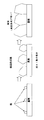
- FIG. 3 is a diagram schematically showing an outline of nucleus and crystal grain growth when an Al alloy film containing a rare earth element such as Sc to Lu is formed by sputtering.
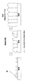
- FIG. 6 is a diagram showing the relationship between the Sc to Lu content and the surface average roughness. It is a figure which shows the relationship between Sc-Lu content rate and initial stage visible light reflectance. It is a figure which shows the outline
- the Al alloy reflective film according to the present invention contains at least one element selected from Sc, Y, La, Gd, Tb and Lu in a total amount of 0.4 to 2.5 at%, with the balance being Al.
- the film surface has an average roughness Ra of 4 nm or less as measured by an atomic force microscope [first invention]. Since the Al alloy reflective film according to the present invention is specified in such a component composition, even when it is formed by sputtering, the average roughness Ra of the film surface is smoothed to 4 nm or less, and the decrease in reflectance is suppressed.
- the Al alloy reflective film according to the present invention by selecting a rare earth element that is alloyed with Al from the viewpoint of improving the alkali resistance of Al, the reflectance of the film in the moisture resistance test, the alkali resistance test, and the acid resistance test is reduced. Discoloration of the film can be suppressed.
- the rare earth element content by setting the rare earth element content to 0.4 to 2.5 at%, it is possible to form an Al alloy film exhibiting a higher reflectance than a pure Al film formed by sputtering. To do.
- the immersion potential becomes a lower potential than that of pure Al, so that it becomes difficult for Al to dissolve and acid resistance. Improve the acidity and secure a sufficiently excellent acid resistance.
- the rare earth element has a low immersion potential, and during dissolution, precipitates on the surface of an Al-rare earth element alloy (hereinafter also referred to as an Al-REM alloy) and concentrates. It becomes a protective film and the dissolution rate is reduced.
- the rare earth elements effective for reducing the dissolution rate are Sc, Y, La, Ce, Nd, Pr, Gd, Dy, Tb, Ho, Er, Tm, and Lu. Further, among these elements, Sc, Y, La, Gd, Tb, and Lu (hereinafter also referred to as Sc to Lu) are preferable.
- Sc to Lu are elements that are difficult to be colored even if they are precipitated as hydroxides on the surface of the Al-REM alloy, they are hardly discolored even after being immersed in an alkaline aqueous solution.
- the hydroxides of rare earth elements such as Ce other than Sc to Lu have a color such as yellow or brown, and thus cause discoloration when precipitated and concentrated on the surface of the Al-REM alloy. Such discoloration is not preferable because it deteriorates the appearance of the reflective film.
- the element alloyed with Al is preferably Y, La, Gd, Tb, Lu, more preferably La, Gd.
- the reflectance is improved. That is, even when a film is formed by sputtering, a decrease in reflectance is suppressed and a high reflectance can be obtained.
- the nucleation density of Al is lowered and the reflectance is impaired.
- increasing the power at the time of film formation or reducing the distance between the substrate and the target leads to an increase in the energy of the sputtered particles, increasing the surface roughness and reducing the reflectance. Therefore, it is necessary to appropriately change the film forming conditions according to the apparatus to be used.
- the content of rare earth elements such as Sc to Lu is preferably 0.4 to 2.5 at%. This is because if the amount is less than 0.4 at%, the crystal grains are not refined and the reflectance is not improved. More preferably, it is 0.5 at% or more. On the other hand, if it exceeds 2.5 at%, the reflectance will be lower than 88%. Therefore, the content of rare earth elements to be alloyed with Al is preferably 2.5 at% or less, more preferably 1 at. % Or less.
- the Al alloy reflective film according to the present invention contains Sc to Lu (Sc, Y, La, Gd, Tb, Lu) in a total amount of 0.4 to 2.5 at%, with the balance being Al and inevitable.
- the Al alloy reflective film according to the present invention has a high reflectance by suppressing a decrease in reflectance even when formed by a sputtering method, and has excellent alkali resistance (corrosion resistance to alkali), It has acid resistance (corrosion resistance to acid) and moisture resistance (resistance in a high temperature and high humidity environment), and even when the protective coating has a defect, the reflectance is hardly lowered. Therefore, it can be suitably used as a reflective film and is useful.
- the Al alloy reflective film according to the present invention has a small surface roughness even when it is formed by sputtering.
- the average roughness Ra of the film surface measured with an atomic force microscope is 4 nm or less [first invention].
- the thickness of the plasma polymerized film is desirably 10 to 1000 nm.
- the film may not be a continuous film, and the meaning of laminating the plasma polymerized film is lost.
- the plasma polymerization film exceeds 1000 nm, the plasma polymerization film causes a decrease in reflectance, which is not preferable.
- the plasma polymerized film is preferably formed using organic silicon as a raw material. Examples of the organic silicon include hexamethyldisiloxane, hexamethyldisilazane, and triethoxysilane.
- the automotive lamp and the lighting device according to the present invention have the Al alloy reflective film according to the present invention as the reflective film (second and third inventions), Further, the present invention is characterized in that the reflective film laminate includes the reflective film laminate according to the fourth invention of the present invention (having the Al alloy reflective film according to the present invention) [Fifth, Sixth] invention ⁇ .
- these have high reflectivity by suppressing the decrease in reflectivity even when the constituent Al alloy reflective film is formed by sputtering, and have excellent alkali resistance (corrosion resistance to alkali) and acid resistance ( Even if the protective coating has defects such as corrosion resistance to acid) and moisture resistance (resistance in a high-temperature and high-humidity environment), the reflectance is hardly lowered, which is useful.
- the Al alloy sputtering target according to the present invention contains at least one element selected from Sc, Y, La, Gd, Tb, and Lu in a total amount of 0.4 to 4.5 at%, with the balance being the remainder. It is characterized by comprising Al and inevitable impurities [seventh invention].
- the Al alloy reflective film according to the present invention as described above can be formed.
- the reason for the difference between the sputtering target composition and the film composition is unclear, but it is thought that the rare earth element once taken into the film is re-sputtered by newly sputtered particles. .
- the yields are in the order of Y> Gd> La, and this is correlated with the order of atomic radii. If the atomic radius is large, the area is large and the probability of resputtering is considered to be high.
- the production method of the Al alloy sputtering target is not particularly limited, and various methods can be applied, but it is desirable to apply the spray forming method. This is because the Al alloy sputtering target manufactured by the spray forming method is excellent in the uniformity of the component structure, and as a result, an Al alloy reflective film having a uniform component structure can be formed [8th invention].
- Example 1 Comparative Example 1
- An Al alloy film having the composition shown in Table 1 was formed on a glass substrate (Corning # 1737) using a DC magnetron sputtering apparatus. Details of this film forming method will be described below.
- a sputtering target for forming an Al alloy film As a sputtering target for forming an Al alloy film, a sputtering target obtained by attaching a chip of a desired metal element (a metal element to be added) on a pure Al sputtering target having a diameter of 100 mm and a thickness of 5 mm is attached to an electrode in a chamber of a sputtering apparatus. After that, the pressure in the chamber was evacuated to 1.3 ⁇ 10 ⁇ 3 Pa or less. When forming a pure Al film, only a pure Al sputtering target was used as a sputtering target.
- the composition of the Al alloy film was changed by changing the metal element type and the number of chips attached on the pure Al sputtering target, and the film formation time was adjusted to 150 nm.
- the Al alloy film specimen obtained by such film formation is subjected to composition analysis, reflectance measurement, and roughness measurement by the following methods, and durability evaluation is performed by moisture resistance test and alkali resistance test-1. Went.
- composition of the Al alloy film was examined by ICP (Inductively Coupled Plasma) emission analysis. That is, the test specimen is dissolved using an acid capable of dissolving the Al alloy film, and the amounts of Al and additive elements in the resulting solution are measured by ICP emission analysis, normalized to 100%, and Al alloy is obtained.
- the composition of the film (unit: at%) was used.
- ⁇ Visible light reflectance measurement> The reflectance in the wavelength range of 250 nm to 800 nm was measured for the specimen formed on the glass substrate, and the visible light reflectance was calculated according to JIS 3106.
- Roughness was measured using a test specimen formed on a glass substrate. The roughness was calculated as an average roughness Ra by observing the roughness shape of the surface of the specimen using an atomic force microscope.
- ⁇ Moisture resistance test> The specimen was held in a furnace maintained at 55 ° C. and 95 RH% for 240 hours, and then removed from the furnace. Thereafter, a light transmission test was performed in which the reflection film of the reflection film laminate was held facing the fluorescent lamp in an environment with an indoor illuminance of 320 lux under a fluorescent lamp, and the presence or absence of light transmission was observed visually. A sample in which light transmission was not observed after the moisture resistance test was “ ⁇ ”, a sample in which light transmission was recognized was “x”, and “ ⁇ ” was determined to be acceptable.
- ⁇ Alkali resistance test-1> The test specimen is immersed in a 1% by mass KOH aqueous solution for 10 minutes, then washed with water and dried, and then the reflective film of the reflective film laminate is directed toward the fluorescent lamp in an environment with an indoor illumination of 320 lux under the fluorescent lamp. Then, the presence or absence of light transmission was visually observed. Moreover, the presence or absence of the discoloration of a film
- those that did not transmit light were marked with “ ⁇ ”, those that partly transmitted light were “ ⁇ ”, and those that were almost transparent were marked “x”. Further, “ ⁇ ” indicates that the film was not discolored, and “ ⁇ ” indicates that the discoloration was observed. Both the transmission of light and the discoloration of the film were judged as “good”.
- Table 1 shows the film composition, the rare earth element content, the initial visible light reflectance, the average roughness, the moisture resistance test and the alkali resistance test result of the reflective film of each reflective film laminate.
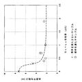
- FIG. 3 shows the relationship between the content of Sc to Lu and the average roughness measured with an atomic force microscope. Furthermore, the relationship between the Sc to Lu content and the initial visible light reflectance is shown in FIG. In FIGS. 3 and 4, the crosses indicate data that does not satisfy the requirements of the first invention of the present invention, and the circles indicate data that satisfy the requirements of the first invention of the present invention.
- those that do not satisfy the requirements of the first invention of the present invention have an average roughness of the film surface measured by an atomic force microscope of more than 4 nm and an initial visible light reflectance of less than 88%.
- the film satisfying the requirements of the first invention of the present invention has an average roughness of the film surface measured by an atomic force microscope of 4 nm or less and an initial visible light reflectance of 88 or more. Indicates.
- Comparative Example 1-1 is a pure Al film, and since the film formed by sputtering has a rough surface, the reflectance is smaller than 88% of the theoretical reflectance. Further, after the alkali resistance test-1, almost the entire surface of the film was dissolved, and the film was transparent.
- Comparative Example 1-3 shows that the reflectance of the Al alloy film is less than 88% because the amount of addition is more than 2.5 at% even if the alloy metal is one of Sc to Lu.
- Comparative Example 1-4 shows that the amount of Sc to Lu is within the claimed range, but the average roughness is over 4 nm and the initial reflectance is less than 88%. This is because the power is 500 W and the substrate-target distance is 45 mm, so that the energy of sputtered particles increases and the nucleation density decreases.
- Comparative Example 1-5 does not satisfy the requirements of the first invention of the present invention, and a rare earth element that discolors the Al film in the alkali resistance test is selected as the alloy element. Although no permeation was observed, discoloration was observed on almost the entire surface of the film.
- Comparative Example 1-6 Mg was added as an alloying element.
- the film became transparent in the moisture resistance test, and light transmission was observed after the moisture resistance test. Almost the entire surface was dissolved, and transparency of the film was observed.
- Comparative Example 1-7 since the rare earth element which does not satisfy the requirements of the first invention of the present invention and has no effect on the alkali resistance is selected as the alloy element, almost the entire surface of the film is included in the alkali resistance test-1. Was dissolved and the film became transparent.
- the Al alloy film satisfies the requirements of the first invention of the present invention, has high durability, and according to the moisture resistance test and the alkali resistance test-1. However, no film transparency or discoloration was observed.
- Example 2 comparative example 2
- Test specimens on which various Al alloy films similar to those in Example 1 were formed were produced, and a reflective film laminate was produced using these specimens. Details of the manufacturing method will be described below.
- the test body obtained by the film formation was placed in a chamber of a plasma CVD apparatus as shown in FIG. 5, and the inside of the chamber was evacuated to 1.3 ⁇ 10 ⁇ 3 Pa or less. Thereafter, the needle valve between the bubbler and the chamber in the apparatus is opened, the vapor of the organic silicon in the bubbler is introduced into the chamber, and the open / close degree of the needle valve is adjusted, so that the pressure in the chamber is 1.3 Pa. .
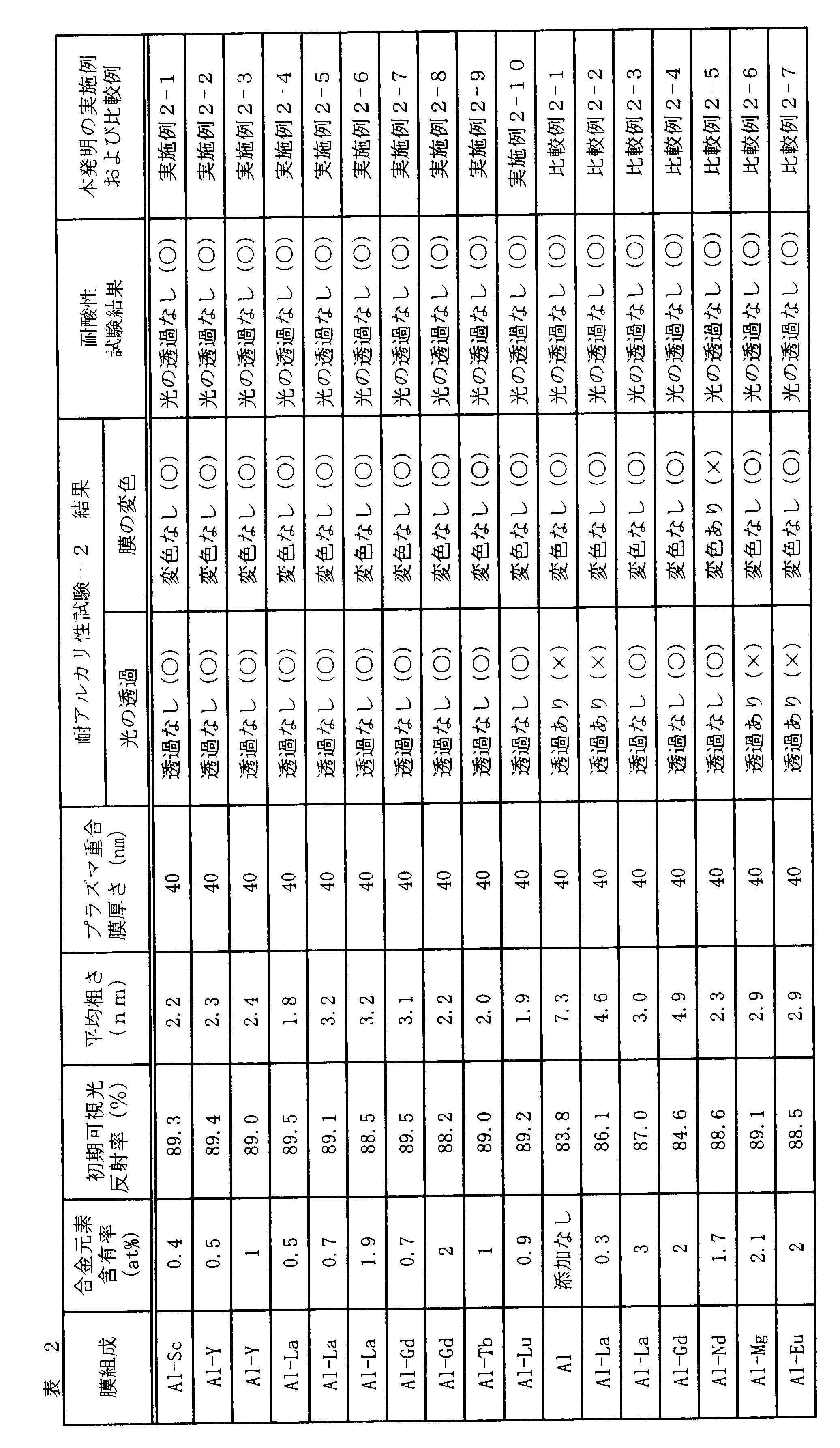
- RF was applied to the upper electrode in the chamber to generate plasma with a power of 200 W, and a plasma polymerization film having a thickness of 40 nm was formed on the test body to obtain a reflection film laminate.
- hexamethyldisiloxane was used as the organic silicon.
- the thus obtained reflective film laminate was subjected to alkali resistance test-2 and acid resistance test. These tests were performed by the following method.
- ⁇ Alkali resistance test-2> The reflective film laminate is immersed in a 1% by mass aqueous KOH solution for 60 minutes, then washed with water, dried, and then the reflective film of the reflective film laminate is placed on the fluorescent lamp side in an environment with an indoor illuminance of 320 lux under a fluorescent lamp. And visually observed the presence or absence of light transmission. Moreover, the presence or absence of the discoloration of a film
- a sample in which no light transmission was observed after the alkali resistance test-2 was indicated as “ ⁇ ”, and a sample in which light transmission was recognized was indicated as “x”.
- “ ⁇ ” indicates that the film was not discolored, and “ ⁇ ” indicates that the discoloration was observed. Both the transmission of light and the discoloration of the film were judged as “good”.
- ⁇ Acid resistance test> The reflective film laminate is immersed in a 1% by mass H 2 SO 4 aqueous solution for 30 minutes, then washed with water and dried, and then the reflective film of the reflective film laminate is subjected to an indoor illumination of 320 lux under a fluorescent lamp. It was held over the fluorescent lamp side and the presence or absence of light transmission was observed visually. Moreover, the presence or absence of the discoloration of a film
- the Al alloy film itself has high durability, and a protective film is formed on the Al alloy film itself, and even after a very severe alkali resistance test-2. No light transmission or discoloration of the film was observed. Also, no light transmission was observed after the acid resistance test. Therefore, even when there is a pinhole in the protective film, it is possible to suppress deterioration of the film and a decrease in reflectance, so that it can be suitably used as a reflective film.
- Example 3 Comparative Example 3
- Examples of the sputtering target for forming an Al alloy film will be described below.
- Al—Y alloy, Al—La alloy and Al—Gd alloy sputtering target (diameter: 100 mm, thickness: 5 mm) of various compositions were prepared by spray forming method, and glass substrate by the same apparatus and method as in Examples 1 and 2.
- An Al alloy film having a thickness of 150 nm was formed thereon to obtain a test specimen.
- the composition analysis is performed on the Al alloy film specimen obtained in this way to measure the alloy composition of the film, and the visible light reflectance of the Al alloy film specimen is determined by the visible light reflectance measurement method. Asked.
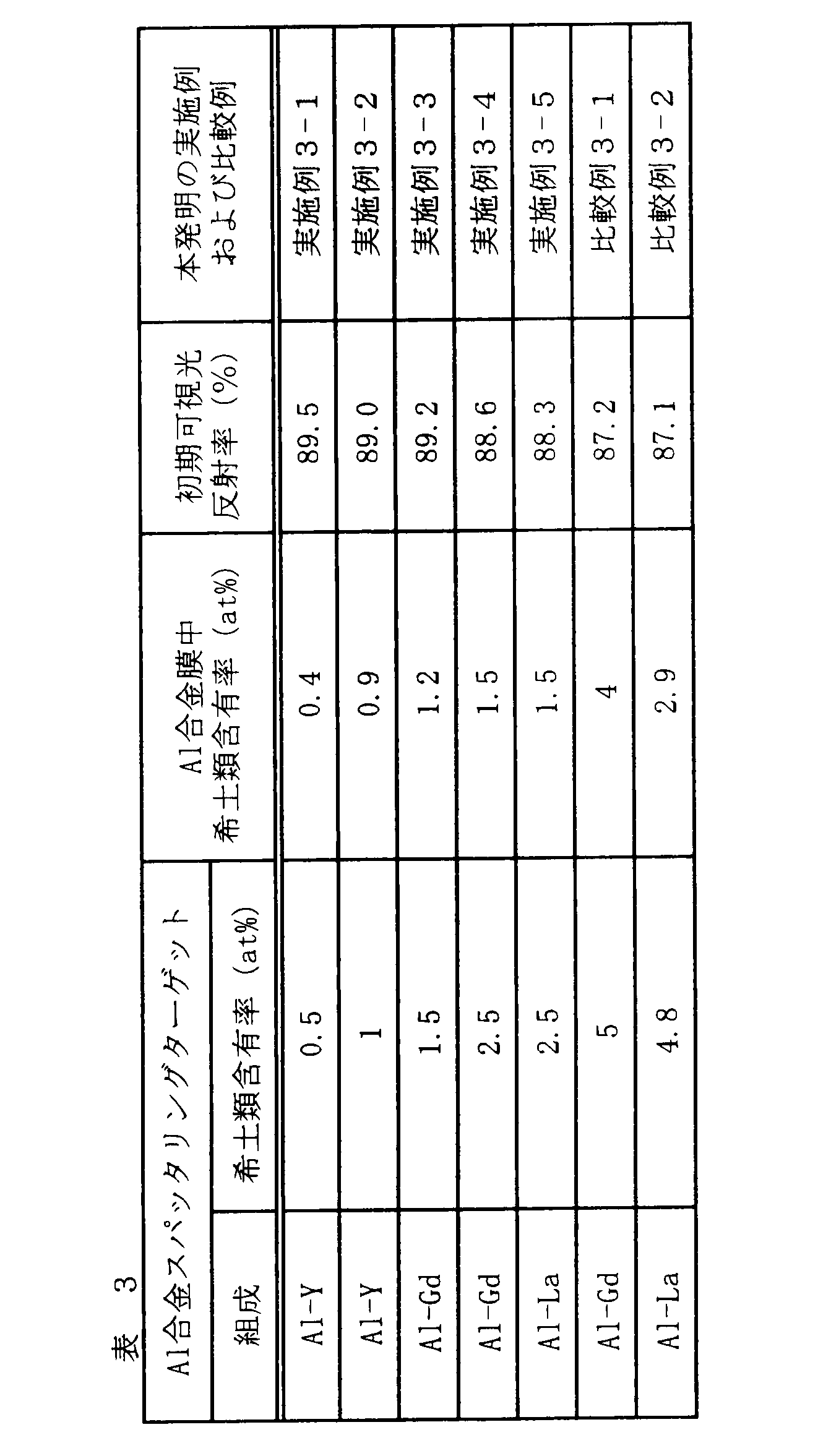
- Table 3 shows the Al alloy target composition, Al alloy film composition measurement results, and visible light reflectance measurement results used.
- Comparative Examples 3-1 and 2 since the composition of the Al alloy sputtering target is higher than the specified range of the present invention, the concentration of rare earth elements in the Al alloy film is high, and the initial visible light reflectance is 88%. Smaller than.
- Examples 3-1 to 5 which are examples of the present invention
- the composition of the Al alloy film formed using the Al alloy sputtering target is also the present invention. Therefore, the visible light reflectance of the Al alloy film is a high value of 88% or more. Therefore, by adjusting the composition of the Al alloy sputtering target within the specified range of the present invention, an Al alloy film having a high visible light reflectance of 88% or more can be formed.
- the Al alloy reflective film according to the present invention has a high reflectivity by suppressing a decrease in reflectivity even when formed by sputtering, and has excellent alkali resistance (corrosion resistance against alkali) and acid resistance (corrosion resistance against acid).
- alkali resistance corrosion resistance against alkali
- acid resistance corrosion resistance against acid
Landscapes
- Chemical & Material Sciences (AREA)
- Engineering & Computer Science (AREA)
- Materials Engineering (AREA)
- Mechanical Engineering (AREA)
- Metallurgy (AREA)
- Organic Chemistry (AREA)
- Chemical Kinetics & Catalysis (AREA)
- Physics & Mathematics (AREA)
- Inorganic Chemistry (AREA)
- General Physics & Mathematics (AREA)
- Optics & Photonics (AREA)
- Physical Vapour Deposition (AREA)
- Optical Elements Other Than Lenses (AREA)
- Non-Portable Lighting Devices Or Systems Thereof (AREA)
- Powder Metallurgy (AREA)
Abstract
Description
DCマグネトロンスパッタリング装置を用いて、表1に示す組成のAl合金膜をガラス基板(コーニング#1737)上にそれぞれ成膜した。この成膜の方法の詳細を以下説明する。
Al合金膜の組成は、ICP(Inductively Coupled Plasma:誘導結合プラズマ)発光分析法によって調べた。即ち、Al合金膜を溶解できる酸を用いて試験体を溶解し、得られた溶解液中のAlと添加元素の量をICP発光分析法により測定し、それを100%に規格化してAl合金膜の組成(単位はat%)とした。
ガラス基板に成膜した試験体に対して、波長が250nm~800nmの範囲の反射率を測定し、JIS 3106に従って可視光反射率を算出した。
ガラス基板に成膜した試験体を用いて粗さ測定を行なった。粗さは、原子間力顕微鏡を用いて試験体表面の粗さ形状を観察し、その平均粗さRaとして算出した。
試験体を55℃・95RH%に保持した炉内に240時間保持した後、炉内から取り出した。その後、蛍光灯下における室内照度320ルックスの環境にて反射膜積層体の反射膜を蛍光灯側に向けるようにかざし、光の透過の有無を目視にて観察する光透過試験を行なった。耐湿性試験後に光の透過が認められなかったものを「○」、光の透過が認められたものを「×」とし、「○」を合格と判断した。
試験体を1質量%KOH水溶液中に10分間浸漬させ、その後、水洗し、乾燥させた後、蛍光灯下における室内照度320ルックスの環境にて反射膜積層体の反射膜を蛍光灯側に向けるようにかざし、光の透過の有無を目視にて観察した。また、前記条件下で、膜の変色の有無を目視にて観察した。耐アルカリ性試験-1後に光の透過が認められなかったものを「○」、一部で光の透過が認められたものを「△」、ほぼ全面が透明化したものを「×」とした。また、膜の変色が認めらなかったものを「○」、変色が認められたものを「×」とした。光の透過および膜の変色のいずれもが「○」を合格と判断した。
実施例1と同様の各種Al合金膜を形成した試験体を作製し、これらを用いて反射膜積層体を作製した。この作製の方法の詳細を以下説明する。前記成膜で得られた試験体を図5に示すようなプラズマCVD装置のチャンバー内に設置し、チャンバー内を1.3×10⁻³Pa以下となるように真空に引いた。その後、前記装置中のバブラーとチャンバー間のニードルバルブを開いてバブラー内の有機シリコンの蒸気をチャンバー内に導入し、ニードルバルブの開閉度を調整することにより、チャンバー内圧力を1.3Paとした。その後、チャンバー内の上部電極にRFを印加し、200Wのパワーでプラズマを発生させ、試験体上に厚さ40nmのプラズマ重合膜を形成して反射膜積層体を得た。なお、上記有機シリコンとしては、ヘキサメチルジシロキサンを用いた。
反射膜積層体を1質量%KOH水溶液中に60分間浸漬させ、その後、水洗し、乾燥させた後、蛍光灯下における室内照度320ルックスの環境にて反射膜積層体の反射膜を蛍光灯側に向けるようにかざし、光の透過の有無を目視にて観察した。また、前記条件下で、膜の変色の有無を目視にて観察した。耐アルカリ性試験-2の後に光の透過が認められなかったものを「○」、光の透過が認められたものを「×」とした。また、膜の変色が認められなったものを「○」、変色が認められたものを「×」とした。光の透過および膜の変色のいずれもが「○」を合格と判断した。
反射膜積層体を1質量%H2SO4水溶液中に30分間浸積し、その後、水洗、乾燥させた後、蛍光灯下における室内照度320ルックスの環境にて反射膜積層体の反射膜を蛍光灯側に向けるようにかざし、光の透過の有無を目視にて観察した。また、前記条件下で、膜の変色の有無を目視にて観察した。耐酸性試験後に光の透過が認められなかったもの「○」、光の透過が認められたものを「×」とし、「○」を合格と判断した。
Al合金膜形成用のスパッタリングターゲットの実施例を以下説明する。

Claims (8)
- Sc、Y、La、Gd、Tb及びLuから選ばれる1種以上の元素を合計で0.4~2.5at%含有し、残部がAlおよび不可避的不純物からなり、原子間力顕微鏡で測定した膜表面の平均粗さRaが4nm以下であることを特徴とするAl合金反射膜。
- 反射膜として請求項1記載のAl合金反射膜を有していることを特徴とする自動車用灯具。
- 反射膜として請求項1記載のAl合金反射膜を有していることを特徴とする照明具。
- 請求項1記載のAl合金反射膜の上にプラズマ重合膜が形成されていることを特徴とする反射膜積層体。
- 反射膜積層体として請求項4記載の反射膜積層体を有していることを特徴とする自動車用灯具。
- 反射膜積層体として請求項4記載の反射膜積層体を有していることを特徴とする照明具。
- 請求項1記載のAl合金反射膜を形成するためのAl合金スパッタリングターゲットであって、Sc、Y、La、Gd、Tb及びLuから選ばれる1種以上の元素を合計で0.4~4.5at%含有し、残部がAlおよび不可避的不純物からなることを特徴とするAl合金スパッタリングターゲット。
- スプレイフォーミング法により製造された請求項7記載のAl合金スパッタリングターゲット。
Priority Applications (2)
| Application Number | Priority Date | Filing Date | Title |
|---|---|---|---|
| CN201080024297.5A CN102460233B (zh) | 2009-06-15 | 2010-06-15 | 铝合金反射膜、反射膜层叠体及汽车用灯具、照明设备以及铝合金溅射靶 |
| US13/320,673 US20120064370A1 (en) | 2009-06-15 | 2010-06-15 | Aluminum alloy reflective film, reflective film laminate, automotive lighting device, illumination device, and aluminum alloy sputtering target |
Applications Claiming Priority (2)
| Application Number | Priority Date | Filing Date | Title |
|---|---|---|---|
| JP2009-142389 | 2009-06-15 | ||
| JP2009142389 | 2009-06-15 |
Publications (1)
| Publication Number | Publication Date |
|---|---|
| WO2010147124A1 true WO2010147124A1 (ja) | 2010-12-23 |
Family
ID=43356441
Family Applications (1)
| Application Number | Title | Priority Date | Filing Date |
|---|---|---|---|
| PCT/JP2010/060146 Ceased WO2010147124A1 (ja) | 2009-06-15 | 2010-06-15 | Al合金反射膜、反射膜積層体、及び、自動車用灯具、照明具、ならびに、Al合金スパッタリングターゲット |
Country Status (4)
| Country | Link |
|---|---|
| US (1) | US20120064370A1 (ja) |
| JP (1) | JP2011021275A (ja) |
| CN (1) | CN102460233B (ja) |
| WO (1) | WO2010147124A1 (ja) |
Families Citing this family (7)
| Publication number | Priority date | Publication date | Assignee | Title |
|---|---|---|---|---|
| JP4611417B2 (ja) * | 2007-12-26 | 2011-01-12 | 株式会社神戸製鋼所 | 反射電極、表示デバイス、および表示デバイスの製造方法 |
| JP5890256B2 (ja) * | 2012-06-06 | 2016-03-22 | ジオマテック株式会社 | アルミニウム合金膜 |
| US9874328B2 (en) | 2014-09-24 | 2018-01-23 | Truck-Lite Co., Llc | Headlamp with lens reflector subassembly |
| JP6647898B2 (ja) | 2016-02-05 | 2020-02-14 | 株式会社コベルコ科研 | 紫外線反射膜およびスパッタリングターゲット |
| JP7424854B2 (ja) * | 2020-02-14 | 2024-01-30 | アルバックテクノ株式会社 | 成膜処理用部品及び成膜装置 |
| KR20220033650A (ko) * | 2020-09-09 | 2022-03-17 | 삼성디스플레이 주식회사 | 반사 전극 및 이를 포함하는 표시 장치 |
| JP7832832B2 (ja) * | 2022-03-31 | 2026-03-18 | 本田技研工業株式会社 | アルミニウム合金からなる積層造形用の粉体金属材料、及び積層造形方法 |
Citations (4)
| Publication number | Priority date | Publication date | Assignee | Title |
|---|---|---|---|---|
| JPH07301705A (ja) * | 1994-05-10 | 1995-11-14 | Kobe Steel Ltd | Al合金薄膜およびAl合金薄膜形成用スパッタリングターゲット |
| JP2003279715A (ja) * | 2002-03-25 | 2003-10-02 | Hitachi Metals Ltd | 平面表示装置用Ag合金系反射膜、Ag合金系反射膜形成用スパッタリングターゲット材および平面表示装置 |
| JP2006091698A (ja) * | 2004-09-27 | 2006-04-06 | Pentax Corp | 耐熱性高反射ミラー |
| WO2007083655A1 (ja) * | 2006-01-17 | 2007-07-26 | Mitsubishi Rayon Co., Ltd. | 熱可塑性樹脂組成物および光反射体 |
Family Cites Families (12)
| Publication number | Priority date | Publication date | Assignee | Title |
|---|---|---|---|---|
| JPH0637695B2 (ja) * | 1988-03-17 | 1994-05-18 | 健 増本 | 耐食性アルミニウム基合金 |
| WO1992013360A1 (fr) * | 1991-01-17 | 1992-08-06 | Mitsubishi Kasei Corporation | Couche de cablage a base d'alliage d'aluminium, son procede de fabrication et cible de depot d'alliage d'aluminium par pulverisation |
| JPH05198026A (ja) * | 1991-09-09 | 1993-08-06 | Shin Etsu Chem Co Ltd | 光磁気記録媒体 |
| EP0531808B1 (en) * | 1991-09-09 | 1997-02-05 | Shin-Etsu Chemical Co., Ltd. | Magneto-optical recording medium |
| JP3773320B2 (ja) * | 1997-01-09 | 2006-05-10 | 新明和工業株式会社 | 成膜装置及び成膜方法 |
| JP3365978B2 (ja) * | 1999-07-15 | 2003-01-14 | 株式会社神戸製鋼所 | 半導体デバイス電極用Al合金薄膜及び半導体デバイス電極用Al合金薄膜形成用のスパッタリングターゲット |
| JP3836657B2 (ja) * | 2000-03-31 | 2006-10-25 | 株式会社小糸製作所 | ライン式膜形成方法 |
| JP2001312840A (ja) * | 2000-04-28 | 2001-11-09 | Tosoh Corp | 表面読み出し型光記録媒体 |
| KR100506474B1 (ko) * | 2002-03-25 | 2005-08-03 | 히타치 긴조쿠 가부시키가이샤 | Ag 합금막 및 Ag 합금막 형성용 스퍼터링 타겟재 |
| US20050112019A1 (en) * | 2003-10-30 | 2005-05-26 | Kabushiki Kaisha Kobe Seiko Sho(Kobe Steel, Ltd.) | Aluminum-alloy reflection film for optical information-recording, optical information-recording medium, and aluminum-alloy sputtering target for formation of the aluminum-alloy reflection film for optical information-recording |
| JP4621989B2 (ja) * | 2005-03-10 | 2011-02-02 | 三菱マテリアル株式会社 | 耐腐食性に優れた反射板用反射膜およびこの耐腐食性に優れた反射板用反射膜を形成するためのスパッタリングターゲット |
| US20090004464A1 (en) * | 2007-06-26 | 2009-01-01 | Diehl David A | Light-Reflective Articles and Methods for Making Them |
-
2010
- 2010-06-14 JP JP2010134874A patent/JP2011021275A/ja active Pending
- 2010-06-15 US US13/320,673 patent/US20120064370A1/en not_active Abandoned
- 2010-06-15 CN CN201080024297.5A patent/CN102460233B/zh not_active Expired - Fee Related
- 2010-06-15 WO PCT/JP2010/060146 patent/WO2010147124A1/ja not_active Ceased
Patent Citations (4)
| Publication number | Priority date | Publication date | Assignee | Title |
|---|---|---|---|---|
| JPH07301705A (ja) * | 1994-05-10 | 1995-11-14 | Kobe Steel Ltd | Al合金薄膜およびAl合金薄膜形成用スパッタリングターゲット |
| JP2003279715A (ja) * | 2002-03-25 | 2003-10-02 | Hitachi Metals Ltd | 平面表示装置用Ag合金系反射膜、Ag合金系反射膜形成用スパッタリングターゲット材および平面表示装置 |
| JP2006091698A (ja) * | 2004-09-27 | 2006-04-06 | Pentax Corp | 耐熱性高反射ミラー |
| WO2007083655A1 (ja) * | 2006-01-17 | 2007-07-26 | Mitsubishi Rayon Co., Ltd. | 熱可塑性樹脂組成物および光反射体 |
Also Published As
| Publication number | Publication date |
|---|---|
| CN102460233B (zh) | 2014-09-03 |
| JP2011021275A (ja) | 2011-02-03 |
| US20120064370A1 (en) | 2012-03-15 |
| CN102460233A (zh) | 2012-05-16 |
Similar Documents
| Publication | Publication Date | Title |
|---|---|---|
| US7452604B2 (en) | Reflective Ag alloy film for reflectors and reflector provided with the same | |
| WO2010147124A1 (ja) | Al合金反射膜、反射膜積層体、及び、自動車用灯具、照明具、ならびに、Al合金スパッタリングターゲット | |
| KR100491931B1 (ko) | 반사 필름, 반사형 액정 표시소자 및 상기 반사 필름을형성하기 위한 스퍼터링 타겟 | |
| WO2010101160A1 (ja) | Al合金反射膜、及び、自動車用灯具、照明具、装飾部品、ならびに、Al合金スパッタリングターゲット | |
| JP2010204291A (ja) | Al合金反射膜、及び、自動車用灯具、照明具、装飾部品、ならびに、Al合金スパッタリングターゲット | |
| JP4009564B2 (ja) | リフレクター用Ag合金反射膜、及び、このAg合金反射膜を用いたリフレクター、並びに、このAg合金反射膜のAg合金薄膜の形成用のAg合金スパッタリングターゲット | |
| US8399100B2 (en) | Reflection film, reflection film laminate, LED, organic EL display, and organic EL illuminating instrument | |
| WO2011090207A1 (ja) | 反射膜積層体 | |
| US8603648B2 (en) | Reflective film laminate | |
| JP2012032551A (ja) | 反射積層膜 | |
| JP5097031B2 (ja) | 反射膜、led、有機elディスプレイ及び有機el照明器具 | |
| JP2008191528A (ja) | 反射膜およびその作製方法および照明装置 | |
| JP5260452B2 (ja) | 耐温水性に優れるAl合金反射膜、およびスパッタリングターゲット | |
| TWI621716B (zh) | UV reflective film and sputtering target | |
| JP2008190036A (ja) | 耐凝集性および耐硫化性に優れた反射膜 | |
| WO2006132417A1 (ja) | 反射率・透過率維持特性に優れた銀合金 | |
| WO2006132416A1 (ja) | 反射率・透過率維持特性に優れた銀合金 | |
| JP5144302B2 (ja) | 反射膜積層体 | |
| Chao et al. | Amorphous NTTO optical composite films were deposited by N2-Ar flow ratio gradient RF magnetron sputtering | |
| KR20150086566A (ko) | Ag 합금막 형성용 스퍼터링 타깃 및 Ag 합금막, Ag 합금 반사막, Ag 합금 도전막, Ag 합금 반투과막 | |
| JP2012248461A (ja) | 反射鏡および照明装置 | |
| Lin et al. | Effect of annealing on morphology, optical reflectivity, and stress state of Al–(0.19–0.53) wt.% Sc thin films prepared by magnetron sputtering | |
| CN117930407A (zh) | 一种高性能反射镜及其制备方法与应用 | |
| JP2008046149A (ja) | リフレクター用Ag合金反射膜、リフレクター、および、リフレクター用Ag合金反射膜の形成用のAg合金スパッタリングターゲット | |
| JP2011032533A (ja) | 反射膜積層体 |
Legal Events
| Date | Code | Title | Description |
|---|---|---|---|
| WWE | Wipo information: entry into national phase |
Ref document number: 201080024297.5 Country of ref document: CN |
|
| 121 | Ep: the epo has been informed by wipo that ep was designated in this application |
Ref document number: 10789499 Country of ref document: EP Kind code of ref document: A1 |
|
| WWE | Wipo information: entry into national phase |
Ref document number: 13320673 Country of ref document: US |
|
| NENP | Non-entry into the national phase |
Ref country code: DE |
|
| 122 | Ep: pct application non-entry in european phase |
Ref document number: 10789499 Country of ref document: EP Kind code of ref document: A1 |