WO2010146947A1 - レベリングバルブ - Google Patents
レベリングバルブ Download PDFInfo
- Publication number
- WO2010146947A1 WO2010146947A1 PCT/JP2010/057922 JP2010057922W WO2010146947A1 WO 2010146947 A1 WO2010146947 A1 WO 2010146947A1 JP 2010057922 W JP2010057922 W JP 2010057922W WO 2010146947 A1 WO2010146947 A1 WO 2010146947A1
- Authority
- WO
- WIPO (PCT)
- Prior art keywords
- spool
- diameter portion
- air spring
- air
- annular gap
- Prior art date
- Legal status (The legal status is an assumption and is not a legal conclusion. Google has not performed a legal analysis and makes no representation as to the accuracy of the status listed.)
- Ceased
Links
Images




Classifications
-
- F—MECHANICAL ENGINEERING; LIGHTING; HEATING; WEAPONS; BLASTING
- F16—ENGINEERING ELEMENTS AND UNITS; GENERAL MEASURES FOR PRODUCING AND MAINTAINING EFFECTIVE FUNCTIONING OF MACHINES OR INSTALLATIONS; THERMAL INSULATION IN GENERAL
- F16K—VALVES; TAPS; COCKS; ACTUATING-FLOATS; DEVICES FOR VENTING OR AERATING
- F16K3/00—Gate valves or sliding valves, i.e. cut-off apparatus with closing members having a sliding movement along the seat for opening and closing
- F16K3/30—Details
- F16K3/32—Means for additional adjustment of the rate of flow
-
- B—PERFORMING OPERATIONS; TRANSPORTING
- B60—VEHICLES IN GENERAL
- B60G—VEHICLE SUSPENSION ARRANGEMENTS
- B60G17/00—Resilient suspensions having means for adjusting the spring or vibration-damper characteristics, for regulating the distance between a supporting surface and a sprung part of vehicle or for locking suspension during use to meet varying vehicular or surface conditions, e.g. due to speed or load
- B60G17/02—Spring characteristics, e.g. mechanical springs and mechanical adjusting means
- B60G17/04—Spring characteristics, e.g. mechanical springs and mechanical adjusting means fluid spring characteristics
- B60G17/056—Regulating distributors or valves for hydropneumatic systems
- B60G17/0565—Height adjusting valves
-
- F—MECHANICAL ENGINEERING; LIGHTING; HEATING; WEAPONS; BLASTING
- F16—ENGINEERING ELEMENTS AND UNITS; GENERAL MEASURES FOR PRODUCING AND MAINTAINING EFFECTIVE FUNCTIONING OF MACHINES OR INSTALLATIONS; THERMAL INSULATION IN GENERAL
- F16K—VALVES; TAPS; COCKS; ACTUATING-FLOATS; DEVICES FOR VENTING OR AERATING
- F16K17/00—Safety valves; Equalising valves, e.g. pressure relief valves
- F16K17/02—Safety valves; Equalising valves, e.g. pressure relief valves opening on surplus pressure on one side; closing on insufficient pressure on one side
- F16K17/04—Safety valves; Equalising valves, e.g. pressure relief valves opening on surplus pressure on one side; closing on insufficient pressure on one side spring-loaded
- F16K17/10—Safety valves; Equalising valves, e.g. pressure relief valves opening on surplus pressure on one side; closing on insufficient pressure on one side spring-loaded with auxiliary valve for fluid operation of the main valve
- F16K17/105—Safety valves; Equalising valves, e.g. pressure relief valves opening on surplus pressure on one side; closing on insufficient pressure on one side spring-loaded with auxiliary valve for fluid operation of the main valve using choking or throttling means to control the fluid operation of the main valve
-
- F—MECHANICAL ENGINEERING; LIGHTING; HEATING; WEAPONS; BLASTING
- F16—ENGINEERING ELEMENTS AND UNITS; GENERAL MEASURES FOR PRODUCING AND MAINTAINING EFFECTIVE FUNCTIONING OF MACHINES OR INSTALLATIONS; THERMAL INSULATION IN GENERAL
- F16K—VALVES; TAPS; COCKS; ACTUATING-FLOATS; DEVICES FOR VENTING OR AERATING
- F16K17/00—Safety valves; Equalising valves, e.g. pressure relief valves
- F16K17/18—Safety valves; Equalising valves, e.g. pressure relief valves opening on surplus pressure on either side
-
- B—PERFORMING OPERATIONS; TRANSPORTING
- B60—VEHICLES IN GENERAL
- B60G—VEHICLE SUSPENSION ARRANGEMENTS
- B60G2300/00—Indexing codes relating to the type of vehicle
- B60G2300/10—Railway vehicles
-
- B—PERFORMING OPERATIONS; TRANSPORTING
- B60—VEHICLES IN GENERAL
- B60G—VEHICLE SUSPENSION ARRANGEMENTS
- B60G2500/00—Indexing codes relating to the regulated action or device
- B60G2500/20—Spring action or springs
- B60G2500/202—Height or leveling valve for air-springs
-
- F—MECHANICAL ENGINEERING; LIGHTING; HEATING; WEAPONS; BLASTING
- F15—FLUID-PRESSURE ACTUATORS; HYDRAULICS OR PNEUMATICS IN GENERAL
- F15B—SYSTEMS ACTING BY MEANS OF FLUIDS IN GENERAL; FLUID-PRESSURE ACTUATORS, e.g. SERVOMOTORS; DETAILS OF FLUID-PRESSURE SYSTEMS, NOT OTHERWISE PROVIDED FOR
- F15B13/00—Details of servomotor systems ; Valves for servomotor systems
- F15B13/02—Fluid distribution or supply devices characterised by their adaptation to the control of servomotors
- F15B13/04—Fluid distribution or supply devices characterised by their adaptation to the control of servomotors for use with a single servomotor
- F15B13/0401—Valve members; Fluid interconnections therefor
- F15B13/0405—Valve members; Fluid interconnections therefor for seat valves, i.e. poppet valves
-
- Y—GENERAL TAGGING OF NEW TECHNOLOGICAL DEVELOPMENTS; GENERAL TAGGING OF CROSS-SECTIONAL TECHNOLOGIES SPANNING OVER SEVERAL SECTIONS OF THE IPC; TECHNICAL SUBJECTS COVERED BY FORMER USPC CROSS-REFERENCE ART COLLECTIONS [XRACs] AND DIGESTS
- Y10—TECHNICAL SUBJECTS COVERED BY FORMER USPC
- Y10T—TECHNICAL SUBJECTS COVERED BY FORMER US CLASSIFICATION
- Y10T137/00—Fluid handling
- Y10T137/8593—Systems
- Y10T137/86919—Sequentially closing and opening alternately seating flow controllers
Definitions
- This invention relates to a leveling valve that supplies compressed air to an air spring of a railway vehicle and releases air from the air spring.
- JP2004-52889A and JP2001-315516A issued by the Japan Patent Office in 2004 supply compressed air to the air springs of the railway vehicle or release air from the air springs.
- These leveling valves raise the support position of the vehicle body by supplying compressed air to the air spring from the compressor when the load of the vehicle body increases and the vehicle body sinks into the carriage.
- the air spring air is drained into the atmosphere to lower the support position of the vehicle body.
- the railway vehicle includes a lever that rotates according to a support position of the vehicle body with respect to the carriage.
- the leveling valve selectively connects the air spring passage leading to the air spring to the compressor and the drain according to the rotational position of the lever.
- the leveling valve has a hollow spool with an open end, an enlarged diameter portion formed at the tip of the spool, a spool hole for housing the spool, and the spool hole closed relative to the spool from the axial direction.
- a valve body. The spool is connected to the lever, and is displaced in the axial direction in the spool hole in accordance with the rotation position of the lever.
- the valve body is biased by the spring and is seated in the opening of the spool hole. Compressed air from the compressor is guided around the valve body.
- the hollow portion of the spool communicates with the drain.
- the drain is open to the atmosphere.
- the port of the air spring passage opens into the spool hole facing the outer periphery of the spool on the opposite side of the valve body across the enlarged diameter portion.
- the lever drives the spool in a direction in which the lever moves backward.
- the valve body holds the spool hole in a closed state, but the tip of the spool and the valve body are separated from each other, so that the hollow portion of the spool and the air spring passage facing the outer periphery of the spool are connected to the spool hole and the enlarged diameter portion. And is connected through an annular gap.
- air from the air spring is discharged from the air spring passage into the atmosphere through the annular gap and the hollow portion of the spool.
- the spool When the vehicle body is further lifted with respect to the carriage, the spool is largely retracted to the vicinity of the opening portion of the air spring passage, and as a result, the air in the air spring does not pass through the annular gap between the spool hole and the enlarged diameter portion. Directly into the hollow part of the spool. As a result, the flow cross-sectional area of the flow path extending from the air spring passage to the hollow portion of the spool rapidly increases, and a large amount of air is released into the atmosphere via the air spring passage.
- FIG. 4 shows the above flow characteristics of the leveling valve. That is, when the lever that drives the spool rotates near the neutral position, the leveling valve is used for both the supply of compressed air to the air spring and the release of air from the air spring due to the flow resistance of the annular gap. The air flow rate is small. When the lever rotates beyond a certain angle, the annular gap disappears and the leveling valve circulates a large amount of air.
- FIG. 4 the leveling valve exhibits the same characteristics when compressed air is supplied to the air spring and when air is released from the air spring. That is, the curve of the flow characteristic is FIG. 4 is symmetrical about the vertical axis.
- an object of the present invention is to provide a leveling valve capable of changing a flow rate characteristic when compressed air is supplied to an air spring and when air is discharged from the air spring.
- a leveling valve according to the present invention is a leveling valve that selectively connects a pneumatic supply source and a drain to an air spring, and includes a spool hole having a reduced diameter portion at an opening, and an air spring.
- a spool that is displaced in the axial direction in the spool hole in accordance with a load, and an air spring passage that communicates with the air spring and faces the outer periphery of the spool.
- the spool includes a diameter-enlarged portion and a hollow portion formed on the outer periphery facing the reduced-diameter portion.
- the enlarged diameter portion is formed to have a larger diameter than other portions of the spool, and an annular gap is formed between the enlarged diameter portion and the reduced diameter portion.
- the axial length of the enlarged diameter portion is different from the axial length of the reduced diameter portion.
- the leveling valve further includes a valve body that sits in the opening of the spool hole relative to the spool, a spring that elastically supports the valve body in the seating position, and a lift from the opening of the spool hole of the valve body that is pressed by the spool.
- the first passage connecting one of the air pressure supply source and the drain to the air spring passage through the annular gap, and the other of the air pressure supply source and the drain depending on the displacement of the spool in the backward direction from the valve body.
- a second passage that connects one side to the air spring passage through the annular gap and the hollow portion.
- FIG. 1 is a longitudinal sectional view of a leveling valve according to the present invention.
- FIG. FIG. 2 is an enlarged side view of the main part of the leveling valve for explaining an example regarding the dimension setting of the enlarged diameter part and the reduced diameter part of the leveling valve.
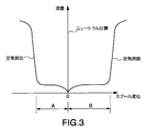
- FIG. 3 is FIG. 2 is a diagram showing the flow characteristics of the leveling valve according to the dimension setting of 2.
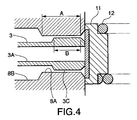
- FIG. 4 is an enlarged side view of the main part of the leveling valve for explaining another example relating to the dimension setting of the enlarged diameter part and the reduced diameter part of the leveling valve.
- FIG. 5 is FIG. 4 is a diagram illustrating a flow characteristic of a leveling valve according to a dimension setting of 4;
- FIG. 6 is a diagram showing the flow characteristics of a leveling valve according to the prior art.
- a leveling valve 1 is interposed between a railway vehicle carriage and a vehicle body supported by the carriage via an air spring, and maintains a constant support height of the vehicle body relative to the carriage.
- the leveling valve 1 is mounted on the vehicle body and is connected to the carriage via a lever 2 and a link.
- the tip of the lever 2 is connected to the spool 3 of the leveling valve 1.
- the leveling valve 1 In response to the displacement of the spool 3, the leveling valve 1 includes an air spring passage 4 connected to an air spring, a first passage 5 connected to a compressor as a pneumatic supply source, and a second passage connected to a drain. 6 is selectively connected. The drain is released to the atmosphere.
- the leveling valve 1 includes a valve housing 7 fixed to the vehicle body.
- a spool hole 8 for accommodating the spool 3 is formed in the valve housing 7. Both ends of the spool hole 8 open into spaces 9 and 10 in the valve housing 7, respectively.
- One space 9 accommodates the connecting portion of the spool 3 and the lever 2.
- a second passage 6 is connected to the space 9.
- a valve body 11 is housed in the space 10.
- the valve body 11 is urged toward the opening portion of the spool hole 8 from the opposite side of the spool 3 by a spring 12 disposed in the space 10, and the opening portion is seated on the valve seat formed in the opening portion. Close against space 10.
- a first passage 5 is connected to the space 10.
- the air spring passage 4 faces the outer periphery of the spool 3 and opens inside the spool hole 8.
- the spool 3 is formed with a hollow portion 3A.
- the hollow portion 3 ⁇ / b> A opens at the end face of the spool 3 facing the valve body 11.
- the hollow portion 3A also communicates with the space 9 at all times via a drain port 3B formed in the radial direction at the opposite end of the spool 3.
- an enlarged diameter portion 3 ⁇ / b> C is formed at the end of the spool 3 facing the valve body 11.
- the spool hole 8 is formed with a reduced diameter portion 8A.
- the spool hole 8 is formed with a sufficiently large diameter with respect to the spool 3. This portion of the spool hole 8 is referred to as an enlarged diameter portion 8B.
- FIG. 1 the spool hole 8 is formed to have a diameter in sliding contact with the spool 3 on the space 9 side from the enlarged diameter portion 8B.
- a ring seal 13 is disposed in the spool hole 8 at this portion.
- the space between the enlarged diameter portion 8B and the spool 3 has a sufficient cross-sectional area that does not give any particular resistance to the air flow.
- the annular gap formed by the reduced diameter portion 8A and the enlarged diameter portion 3C is significantly narrower than this, and generates an apparent resistance against the passage of air.
- the axial length of the reduced diameter portion 8A is A
- the axial length of the expanded diameter portion 3C is B.
- the axial length A of the reduced diameter portion 8A and the axial length B of the enlarged diameter portion 3C are set so as to satisfy the relationship of A ⁇ B.
- the position where the center line of the lever 2 and the center axis of the spool 3 form a right angle is set as the neutral position of the spool 3.
- the spool 3 In the neutral position, the spool 3 abuts the valve body 11 in the closed position. However, the spool 3 does not exert any lift force on the valve body 11 in the neutral position.
- the relationship between the position of the spool 3 and the swing angle of the lever 2 is adjusted in advance.
- the valve element 11 closes the opening of the spool hole 8 and the tip of the spool 3 is in contact with the valve element 11. Therefore, the communication between the space 10 and the air spring passage 4 via the annular gap is blocked.
- the air spring passage 4 is substantially closed, and air is not supplied to or discharged from the air spring.
- the air spring holds the vehicle body at a preset support position.
- This support position corresponds to the neutral position of the vehicle body.
- the leveling valve 1 automatically adjusts the pressure of the air spring to keep the vehicle body in the neutral position against such load fluctuations.
- the spool 3 When the support position of the vehicle body is slightly raised from the neutral position, the spool 3 is driven to the left in the figure via the lever 2. Due to this displacement of the spool 3, the tip of the spool 3 is separated from the valve body 11, and the inside and outside of the spool 3 communicate with each other through a gap formed between the tip of the spool 3 and the valve body 11. More specifically, the hollow portion 3A of the spool 3 and the air spring passage 4 communicate with each other through an annular gap between the reduced diameter portion 8A and the enlarged diameter portion 3C.
- the air in the air spring passes through the air spring passage 4, the annular gap between the reduced diameter portion 8A and the enlarged diameter portion 3C, the gap between the spool 3 and the valve body 11, the hollow portion 3A of the spool 3, and the drain port 3B. Released into the atmosphere. At this time, flow resistance is generated for the air passing through the annular gap between the reduced diameter portion 8A and the enlarged diameter portion 3C. Therefore, the vehicle body descends slowly and reaches the neutral position. When the support position of the vehicle body is significantly raised, the spool 3 is greatly displaced to the left side in the figure.
- the enlarged diameter portion 3C of the spool 3 slips out from the reduced diameter portion 8A to the left side of the drawing, and no annular gap exists.
- the air flowing out from the air spring toward the atmosphere flows out without receiving the flow resistance of the annular gap, so a large amount of air is released from the air spring and the vehicle body descends quickly.
- the leveling valve 1 releases air from the air spring little by little under the resistance of the annular gap, and slowly lowers the support position of the vehicle body.
- the leveling valve 1 releases air from the air spring without the resistance of the annular gap, and quickly lowers the support position of the vehicle body.
- the spool 3 interlocked with the lever 2 is displaced in a direction approaching the valve body 11, and the enlarged diameter portion 3C enters the reduced diameter portion 8A.
- An annular gap is formed between the enlarged diameter portion 3C and the reduced diameter portion 8A.
- the spool 3 comes into contact with the valve body 11 at the tip. Thereafter, the connection between the air spring passage 4 and the drain is cut off, and the release of air from the air spring is also cut off.
- the vehicle body is held in the neutral position until a new change in the load condition occurs.
- the lever 2 drives the spool to the right in the figure. Due to this displacement of the spool 3, the valve body 11 is lifted from the opening of the spool hole 8, and the space 10 and the air spring passage 4 communicate with each other via an annular gap formed by the enlarged diameter portion 3 C and the reduced diameter portion 8 A.
- the tip of the spool 3 Since the tip of the spool 3 is in contact with the valve body 11, the communication between the air spring passage 4 and the drain is blocked. In this state, the compressed air from the compressor flows into the air spring passage 4 through an annular gap formed by the enlarged diameter portion 3C and the reduced diameter portion 8A, and the air spring expands when the compressed air is supplied. At this time, flow resistance is generated for the air passing through the annular gap between the reduced diameter portion 8A and the enlarged diameter portion 3C. Therefore, the vehicle body slowly rises to the neutral position. When the support position of the vehicle body is significantly lowered from the neutral position, the spool 3 is greatly displaced to the right side in the figure.
- the diameter-enlarged portion 3C of the spool 3 protrudes to the outside of the spool hole 8 while pressing the valve body 11, and no annular gap exists.
- the compressed air flowing from the space 10 into the air spring flows through the space between the spool hole 8 and the spool 3 into the air spring passage 4 without resistance. Therefore, a large amount of compressed air is supplied to the air spring, and the air spring quickly raises the support position of the vehicle body.
- the leveling valve 1 supplies compressed air to the air spring from the space 10 through the air spring passage 4 little by little under the resistance of the annular gap. Raise slowly.
- the leveling valve 1 supplies a large amount of compressed air to the air spring without the resistance of the annular gap, and quickly raises the support position of the vehicle body.
- the spool 3 interlocked with the lever 2 is displaced to the left in the figure, and the enlarged diameter portion 3C enters the reduced diameter portion 8A again, and the enlarged diameter portion.
- An annular gap is formed between 3C and the reduced diameter portion 8A.
- FIG. 2 shows the case where the axial length B of the enlarged diameter portion 3C exceeds the axial length A of the reduced diameter portion 8A.
- the annular gap disappears when the displacement distance of the spool 3 reaches A, whereas the spool 3 is displaced in the right direction in the figure. The annular gap does not disappear until the displacement distance of the spool 3 reaches B.
- the flow characteristic of the leveling valve 1 is FIG. As shown in FIG.
- FIG. 4 shows the case where the axial length A of the reduced diameter portion 8A exceeds the axial length B of the enlarged diameter portion 3C. Also in this case, when the spool 3 is displaced in the left direction in the figure, the annular gap disappears when the displacement distance of the spool 3 reaches A, and when the spool is displaced in the right direction in the figure, the displacement of the spool 3 When the distance reaches B, the annular gap disappears.
- the flow rate characteristic of the leveling valve 1 is FIG.
- different flow rate characteristics are shown when air is supplied to the air spring and when air is released from the air spring. That is, a large amount of air is released from the air spring into the atmosphere relatively quickly when the vehicle body is lifted from the neutral position, and the vehicle body descending operation is performed quickly, whereas the vehicle body is moved from the neutral position.
- the flow rate of the compressed air supplied from the space 10 to the air spring is kept small until the vehicle body is lowered significantly. In other words, regarding the raising / lowering of the vehicle body exceeding a certain range, the descending operation of the raised vehicle body is performed more quickly than the ascending operation of the lowered vehicle body.
- the range of the micro flow region by the annular gap is different between the air supply side and the air discharge side in both cases of A> B and B> A.
- the characteristics of the actual air spring are optimally matched according to the rigidity required for the air spring that supports the vehicle body. It becomes possible to make it.
- A> B or B> A should be determined in consideration of the support condition of the vehicle body by the air spring.
- the setting flexibility can be increased by using the leveling valve 1.
- the leveling valve 1 since the leveling valve 1 has an asymmetric flow characteristic, the leveling valve 1 has a preferable characteristic that hunting is unlikely to occur near the neutral position while maintaining high response.
- the contents of Japanese Patent Application No. 2009-145354 in Japan with an application date of June 18, 2009 are incorporated herein by reference.
- the present invention has been described through several specific embodiments, the present invention is not limited to the above embodiments. Those skilled in the art can make various modifications or changes to these embodiments within the scope of the claims.
- the first passage 5 is connected to a compressor as an air pressure supply source
- the second passage 6 is connected to a drain.
- the leveling valve according to the present invention is suitable for automatic adjustment of a support position using an air spring of a railway vehicle body.
Landscapes
- Engineering & Computer Science (AREA)
- General Engineering & Computer Science (AREA)
- Mechanical Engineering (AREA)
- Vehicle Body Suspensions (AREA)
- Fluid-Damping Devices (AREA)
- Multiple-Way Valves (AREA)
- Flow Control (AREA)
Abstract
Description
これらのレベリングバルブは、車体の荷重が増加して車体が台車に対して沈み込むと、コンプレッサから空気ばねに圧縮空気を供給して車体の支持位置を上昇させる。車体の荷重が減少して車体が台車から浮き上がると、空気ばねの空気を大気中にドレーンすることで、車体の支持位置を下降させる。
鉄道車両は台車に対する車体の支持位置に応じて回動するレバーを備えている。レベリングバルブは空気ばねに至る空気ばね通路を、レバーの回動位置に応じて、コンプレッサとドレーンに選択的に接続する。
JP2004−52889Aによれば、レベリングバルブは先端を開口した中空のスプールと、スプール先端に形成した拡径部と、スプールを収装するスプール孔と、スプールに軸方向から相対してスプール孔を閉鎖する弁体とを備える。
スプールはレバーに連結され、レバーの回動位置に応じてスプール孔内を軸方向に変位する。弁体はスプリングに付勢されてスプール孔の開口部に着座する。弁体の周囲にはコンプレッサからの圧縮空気が導かれる。スプールの中空部はドレーンに連通する。ドレーンは大気に解放されている。拡径部を挟んで弁体と反対側のスプールの外周に臨んで空気ばね通路のポートがスプール孔に開口する。
レバーがニュートラル位置にある場合には、弁体は弁座に着座し、スプールは先端を弁体に当接している。この状態では空気ばね通路はコンプレッサからもドレーンからも遮断される。レバーがニュートラル位置にある時の車体の支持位置を車体のニュートラル位置と称する。
ニュートラル位置の車体が台車に対して沈み込むと、回動するレバーが弁体をリフトさせる方向にスプールを駆動する。弁体がリフトすると弁体の周囲にコンプレッサから導かれた圧縮空気が、スプール孔とスプールの拡径部とがなす環状隙間を介して空気ばね通路に流入する。
車体が台車に対してさらに沈み込むと、スプールは弁体をより大きくリフトさせるとともに、拡径部がスプール孔の外側へ突出することで、拡径部とスプール孔との間に形成されていた環状隙間が消滅する。その結果、空気ばね通路に流入する圧縮空気の流通断面積が急激に増大し、大量の圧縮空気が空気ばね通路に供給される。
一方、ニュートラル位置から車体が台車に対して浮き上がると、レバーは弁体から後退する方向にスプールを駆動する。その結果、弁体はスプール孔を閉鎖状態に保持するが、スプールの先端と弁体とが離間するので、スプールの中空部とスプールの外周に臨む空気ばね通路とが、スプール孔と拡径部との環状隙間を介して接続される。その結果、空気ばねの空気が空気ばね通路から環状隙間とスプールの中空部を介して大気中に放出される。
車体が台車に対してさらに浮き上がると、スプールは空気ばね通路の開口部付近まで大きく後退し、結果として空気ばねの空気は、スプール孔と拡径部との環状隙間を介さずに、空気ばね通路から直接スプールの中空部へ流出する。これにより、空気ばね通路からスプールの中空部に至る流路の流通断面積が急激に拡大し、大量の空気が空気ばね通路を介して大気中に放出される。
このようにして、台車に対する車体の支持位置がニュートラル位置の近くにある場合には、空気ばねへの圧縮空気の供給と、レベリングバルブは空気ばねからの空気の放出のいずれについても、環状隙間の流通抵抗のもとで微少流量の空気を流通させ、空気ばねによる車体の支持位置をニュートラル位置へと修正する。一方、台車に対する車体の支持位置がニュートラル位置から大きくはずれた場合には、空気ばねへの空気の供給と空気ばねからの空気の放出のいずれについても、レベリングバルブは環状隙間に規制されない大きな流通断面積のもとで空気を移動させる。大量の空気の移動により空気ばねによる車体の支持位置は速やかにニュートラル位置付近へと修正される。
FIG.4から分かるように、レベリングバルブは空気ばねへの圧縮空気の供給時と、空気ばねからの空気の放出時とで同じ特性を発揮する。すなわち、流量特性の曲線はFIG.4の縦軸を中心に左右対称形をなしている。しかしながら、空気ばねの設計の自由度を確保し、あるいはニュートラル位置付近における空気の給排に関してハンチングが生じないようにするには、空気ばねへの圧縮空気の供給時と、空気ばねからの空気の放出時とで異なる流量特性の設定が必要になる場合がある。
この発明の目的は、したがって、空気ばねへの圧縮空気の供給時と、空気ばねからの空気の放出時とで流量特性を変更可能なレベリングバルブを提供することである。
以上の目的を達成するために、この発明によるレベリングバルブは、空気ばねに空気圧供給源とドレーンとを選択的に接続するレベリングバルブにおいて、開口部に縮径部を有するスプール孔と、空気ばねの負荷に応じてスプール孔内を軸方向に変位するスプールと、空気ばねに連通し、スプールの外周に臨む空気ばね通路と、を備える。スプールは縮径部に面して外周に形成した拡径部と中空部とを備える。拡径部はスプールの他の部位より大径に形成され、拡径部と縮径部との間に環状隙間が形成される。拡径部の軸方向長さと縮径部の軸方向長さは異なる。
レベリングバルブは、さらにスプールに相対してスプール孔の開口部に着座する弁体と、弁体を着座位置に弾性支持するスプリングと、スプールに押圧された弁体のスプール孔の開口部からのリフトに応じて、空気圧供給源及びドレーンの一方を環状隙間を介して空気ばね通路に接続する第1の通路と、スプールの弁体からの後退方向の変位に応じて、空気圧供給源及びドレーンのもう一方を環状隙間と中空部とを介して空気ばね通路に接続する第2の通路と、とを備える。
この発明の詳細並びに他の特徴や利点は、明細書の以下の記載の中で説明されるとともに、添付された図面に示される。
FIG.2はレベリングバルブの拡径部と縮径部の寸法設定に関する一例を説明するレベリングバルブ要部の拡大側面図である。
FIG.3はFIG.2の寸法設定によるはレベリングバルブの流量特性を示すダイアグラムである。
FIG.4はレベリングバルブの拡径部と縮径部の寸法設定に関する他の一例を説明するレベリングバルブ要部の拡大側面図である。
FIG.5はFIG.4の寸法設定によるレベリングバルブの流量特性を示すダイアグラムである。
FIG.6は従来技術によるレベリングバルブの流量特性を示すダイアグラムである。
レベリングバルブ1は車体に装着され、レバー2とリンクとを介して台車に連結される。レバー2の先端はレベリングバルブ1のスプール3に連結される。車体の荷重変化により空気ばねによる車体の支持高さが変化すると、この変化がリンクを介してレバー2を揺動させ、レバー2の先端に連結したスプール3を軸方向に駆動する。レベリングバルブ1はスプール3の変位に応じて、空気ばねに接続された空気ばね通路4に、空気圧供給源としてのコンプレッサに接続された第1の通路5と、ドレーンに接続された第2の通路6を選択的に接続する。なお、ドレーンは大気に解放される。
レベリングバルブ1は車体に固定されるバルブハウジング7を備える。バルブハウジング7にはスプール3を収装するスプール孔8が形成される。スプール孔8の両端はそれぞれバルブハウジング7内のスペース9、10に開口する。一方のスペース9にはスプール3とレバー2の連結部が収装される。スペース9には第2の通路6が接続される。
スペース10には弁体11が収装される。弁体11はスペース10内に配置されたスプリング12により、スプール3と反対側からスプール孔8の開口部に向けて付勢され、開口部に形成された弁座に着座することで開口部をスペース10に対して閉鎖する。スペース10には第1の通路5が接続される。
空気ばね通路4はスプール3の外周に臨んでスプール孔8の内側に開口する。スプール3には中空部3Aが形成される。中空部3Aはスプール3の弁体11に向いた端面に開口する。中空部3Aはまた、スプール3の反対側の端部にラジアル方向に形成したドレーンポート3Bを介してスペース9に常時連通する。
FIG.2を参照すると、スプール3の弁体11に向いた端部には拡径部3Cが形成される。これに対して、スプール孔8には縮径部8Aが形成される。縮径部8Aから空気ばね通路4の開口部に至る区間においてスプール孔8はスプール3に対して十分な大径に形成される。スプール孔8のこの部分を拡径部8Bと称する。
再びFIG.1を参照すると、スプール孔8は拡径部8Bよりスペース9側においては、スプール3に摺接する径に形成される。この部位のスプール孔8にはリングシール13が配置される。
再びFIG.2を参照すると、拡径部8Bとスプール3との間のスペースは空気の流通に格別の抵抗を与えない程度に十分な断面積を備える。一方、縮径部8Aと拡径部3Cとがなす環状隙間はこれより大幅に狭く、空気の通過に対して明らかな抵抗を発生させる。
縮径部8Aの軸方向長さをA、拡径部3Cの軸方向長さをBとする。このレベリングバルブ1においてはA≠Bの関係を満足するように、縮径部8Aの軸方向長さAと拡径部3Cの軸方向長さBを設定する。
再びFIG.1を参照すると、このレベリングバルブ1においてはレバー2の中心線とスプール3の中心軸とが直角をなす位置が、スプール3のニュートラル位置に設定される。スプール3はニュートラル位置において先端を閉鎖位置の弁体11に当接する。ただし、ニュートラル位置ではスプール3は弁体11にいかなるリフト力をも及ぼさない。この状態が得られるように、スプール3の位置とレバー2の揺動角との関係をあらかじめ調整する。
ニュートラル位置のレベリングバルブ1においては、弁体11がスプール孔8の開口部を閉鎖し、スプール3の先端が弁体11に当接している。したがって、環状隙間を介したスペース10と空気ばね通路4との連通は遮断されている。環状隙間を介したスプール3の中空部3Aと空気ばね通路4との連通も遮断されている。そのため、空気ばね通路4は実質的に閉鎖され、空気ばねへの空気の給排は行われない。この状態で、空気ばねは車体をあらかじめ設定された支持位置に保持する。この支持位置が車体のニュートラル位置に相当する。
例えば車両の乗客の乗降により、車体が空気ばねに及ぼす負荷が変動すると、空気ばねが負荷の増減に応じて伸縮し、空気ばねによる車体の支持位置に変化が生じる。レベリングバルブ1はこうした負荷変動に対して車体をニュートラル位置に保つべく空気ばねの圧力を自動調整する。
車体の支持位置がニュートラル位置から僅かに上昇した場合には、レバー2を介してスプール3は図の左側へ駆動される。スプール3のこの変位により、スプール3の先端が弁体11から離間し、スプール3の先端と弁体11の間に生じる隙間を介してスプール3の内側と外側とが連通する。より詳しくは、縮径部8Aと拡径部3Cの間の環状隙間を介してスプール3の中空部3Aと空気ばね通路4とが連通する。その結果、空気ばねの空気が空気ばね通路4、縮径部8Aと拡径部3Cの間の環状隙間、スプール3と弁体11の隙間,スプール3の中空部3A、及びドレーンポート3Bを介して大気に放出される。この時、縮径部8Aと拡径部3Cの環状隙間が通過する空気に対して流通抵抗を発生させる。したがって、車体はゆっくりと降下してニュートラル位置に至る。
車体の支持位置が大幅に上昇した場合には、スプール3は図の左側へ大きく変位する。その結果、スプール3の拡径部3Cは縮径部8Aから図の左側へと抜け出し、環状隙間は存在しなくなる。この状態で空気ばねから大気中に向けて流出する空気は、環状隙間の流通抵抗を受けずに流出するので、大量の空気が空気ばねから放出され、車体は速やかに降下する。
このように、車体の上昇位置がニュートラル位置に近い場合には、レベリングバルブ1は環状隙間の抵抗のもとで少量ずつ空気ばねから空気を放出して、車体の支持位置をゆっくりと降下させる。車体の上昇位置がニュートラル位置から大きく隔たっている場合には、レベリングバルブ1は環状隙間の抵抗なしに、空気ばねから空気を放出し、車体の支持位置を速やか降下させる。
なお、この場合も車体の支持位置がニュートラル位置に近づくと、レバー2に連動するスプール3は弁体11に接近する方向へと変位し、拡径部3Cが縮径部8Aに侵入して、拡径部3Cと縮径部8Aの間に環状隙間を形成する。以後、車体の支持位置は環状隙間の流通抵抗により、ゆっくりと降下し、最終的にニュートラル位置に戻る。
車体の支持位置がニュートラル位置に戻ると同時にスプール3は先端を弁体11に当接する。以後、空気ばね通路4とドレーンの接続は遮断され、空気ばねからの空気の放出も遮断される。車体は荷重条件に新たな変動が生じるまで、ニュートラル位置に保持される。
一方、車体の支持位置がニュートラル位置から僅かに下降した場合には、レバー2はスプールを図の右方向へと駆動する。スプール3のこの変位により弁体11がスプール孔8の開口部からリフトし、スペース10と空気ばね通路4とが拡径部3Cと縮径部8Aによる環状隙間を介して連通する。スプール3の先端が弁体11に当接しているため、空気ばね通路4とドレーンとの連通は遮断される。
この状態では,コンプレッサからの圧縮空気が、拡径部3Cと縮径部8Aによる環状隙間を介して空気ばね通路4に流入し、空気ばねは圧縮空気の供給により膨張する。この時、縮径部8Aと拡径部3Cの環状隙間が通過する空気に対して流通抵抗を発生させる。したがって、車体はゆっくりと上昇してニュートラル位置に至る。
車体の支持位置がニュートラル位置から大幅に下降した場合には、スプール3は図の右側へ大きく変位する。スプール3の拡径部3Cは弁体11を押圧しつつスプール孔8の外側へ突出し、環状隙間は存在しなくなる。この状態でスペース10から空気ばねへと流入する圧縮空気はスプール孔8とスプール3の間のスペースを通って空気ばね通路4に抵抗なく流入する。したがって、大量の圧縮空気が空気ばねに供給され、空気ばねは速やかに車体の支持位置を上昇させる。
このように車体の下降位置がニュートラル位置に近い場合には、レベリングバルブ1は環状隙間の抵抗のもとで少量ずつスペース10から空気ばね通路4を介して空気ばねに圧縮空気を供給し、車体をゆっくりと上昇させる。車体の下降位置がニュートラル位置から大きく隔たっている場合には、レベリングバルブ1は環状隙間の抵抗なしに、空気ばねに大量の圧縮空気を供給し、車体の支持位置を速やかに上昇させる。
なお、この場合も車体の支持位置がニュートラル位置に近づくと、レバー2に連動するスプール3は図の左側へと変位し、拡径部3Cが再び縮径部8Aに侵入して、拡径部3Cと縮径部8Aの間に環状隙間を形成する。以後、車体の支持位置は環状隙間の流通抵抗により、ゆっくりと上昇し、最終的にニュートラル位置に戻る。
このレベリングバルブ1においては、前述のように、スプール孔8の縮径部8Aの軸方向長さAとスプール3の拡径部3Cの軸方向長さBは異なる値に設定される。
FIG.2は拡径部3Cの軸方向長さBが縮径部8Aの軸方向長さAを上回る場合を示す。この場合には、スプール3が図の左方向に変位する場合には、スプール3の変位距離がAに達すると環状隙間が消滅するのに対して、スプール3が図の右方向に変位する場合は、スプール3の変位距離がBに達するまで環状隙間は消滅しない。
その結果、レベリングバルブ1の流量特性はFIG.3に示すように、空気ばねへの空気供給時と空気ばねからの空気放出時とで異なる流量特性を示す。すなわち、スプール3がFIG.2の左方向へ作動する空気放出時においては、スプール3の変位距離がAに達すると流通抵抗が急減して流量が急増するのに対して、スプール3がFIG.2の右方向へ作動する空気供給時においては、同様の減少はスプール3の変位距離がBに達するまで生じない。つまり、車体のニュートラル位置からの下降に対しては、比較的早期に大量の空気が空気ばねに供給され、早期に車体の本格的な上昇操作が実行されるのに対して、車体のニュートラル位置からの上昇に対しては、車体が大幅に上昇するまで、空気ばねから大気に放出する空気の流量が小さく抑えられる。言い換えれば、一定範囲を超えた車体の昇降に関して、降下した車体の上昇操作は、上昇した車体の降下操作より迅速に行われることになる。
FIG.4は縮径部8Aの軸方向長さAが拡径部3Cの軸方向長さBを上回る場合を示す。この場合も、スプール3が図の左方向に変位する場合には、スプール3の変位距離がAに達すると環状隙間が消滅し、スプールが図の右方向に変位する場合は、スプール3の変位距離がBに達すると環状隙間が消滅する。しかしながら、FIG.2のケースと逆にA>Bの関係があるので、レベリングバルブ1の流量特性はFIG.5に示すように、空気ばねへの空気供給時と空気ばねからの空気放出時とで異なる流量特性を示す。すなわち、車体のニュートラル位置からの上昇に対しては比較的早期に空気ばねから大量の空気が大気中に放出され、速やかに車体の降下操作が実行されるのに対して、車体のニュートラル位置からの下降に対しては、車体が大幅に下降するまで、スペース10から空気ばねへ供給される圧縮空気の流量が小さく抑えられる。言い換えれば、一定範囲を超えた車体の昇降に関して、上昇した車体の降下操作は、下降した車体の上昇操作より迅速に行われることになる。
以上のように、このレベリングバルブ1においては、A>Bの場合も、B>Aの場合も、環状隙間による微小流領域の範囲が、空気の供給側と空気の放出側とで互いに異なる。このレベリングバルブ1においては、AとBの値の設定により流量特性の違いを任意に実現なため、車体を支持する空気ばねに求められる剛性に応じて、実際の空気ばねの特性を最適にマッチングさせることが可能になる。なお、A>Bの設定とB>Aの設定のいずれかを選択するかは、空気ばねによる車体の支持条件を考慮して決定すれば良い。
また、車両の好ましい安定度や好ましい乗り心地を実現するための空気ばねの特性の設定に関して、このレベリングバルブ1を用いることで設定の自由度を増加させることができる。
さらに、FIG.3やFIG.5に示すように、このレベリングバルブ1は非対称形の流量特性を備えるため、レベリングバルブ1は高い応答性を維持しつつ、ニュートラル位置付近でハンチングを起こしにくいという好ましい特性をもつ。
以上の説明に関して2009年6月18日を出願日とする日本国における特願2009−145354号、の内容をここに引用により合体する。
以上、この発明をいくつかの特定の実施例を通じて説明してきたが、この発明は上記の各実施例に限定されるものではない。当業者にとっては、クレームの技術範囲でこれらの実施例にさまざまな修正あるいは変更を加えることが可能である。
例えば、上記の実施例では、第1の通路5を空気圧供給源としてのコンプレッサに接続し、第2の通路6をドレーンに接続している。しかしながら、第1の通路5をドレーンに接続し、第2の通路を空気圧供給源としてのコンプレッサに接続することも可能である。
この発明の実施例が包含する排他的性質あるいは特長は以下のようにクレームされる。
Claims (5)
- 空気ぱねに空気圧供給源とドレーンとを選択的に接続するレベリングバルブ(1)において:
開口部に縮径部(8A)を有するスプール孔(8)と;
空気ばねの負荷に応じてスプール孔(8)内を軸方向に変位するスプール(3)、スプール(3)は縮径部(8A)に面して外周に形成した拡径部(3C)と中空部(3A)、拡径部(3C)はスプール(3)の他の部位より大径に形成され、拡径部(3C)と縮径部(8A)との間に環状隙間が形成されるとともに拡径部(3C)の軸方向長さ(B)と縮径部(8A)の軸方向長さ(A)は異なる、とを備える、と;
空気ばねに連通し、スプール(3)の外周に臨む空気ばね通路(4)と;
スプール(3)に相対してスプール孔(8)の開口部に着座する弁体(11)と;
弁体(11)を着座位置に弾性支持するスプリング(12)と;
スプール(3)に押圧された弁体(11)のスプール孔(8)の開口部からのリフトに応じて、空気圧供給源及びドレーンの一方を環状隙間を介して空気ばね通路(4)に接続する第1の通路(5)と;
スプール(3)の弁体(11)からの後退方向の変位に応じて、空気圧供給源及びドレーンのもう一方を環状隙間と中空部(3A)とを介して空気ばね通路(4)に接続する第2の通路(6)と;
を備える。 - クレーム1に記載のレベリングバルブにおいて、拡径部(3C)の軸方向長さ(B)は縮径部(8A)の軸方向長さ(A)より長く設定される。
- クレーム1に記載のレベリングバルブにおいて、縮径部(8A)の軸方向長さ(A)は拡径部(3C)の軸方向長さ(B)より長く設定される。
- クレーム1から3のいずれかに記載のレベリングバルブにおいて、空気ばね通路(4)は環状隙間に常時連通し、第1の通路(5)は空気圧供給源に接続され、第2の通路(6)はドレーンに接続され、弁体(11)はスプール孔(8)の開口部に着座することで第1の通路(5)と環状隙間とを遮断し、スプール孔(8)の開口部からリフトすることで第1の通路(5)と環状隙間とを連通するよう構成され、スプール(3)は弁体(11)に当接することで中空部(3A)と環状隙間とを遮断し、弁体(11)から後退方向に変位することで、中空部(3A)と環状隙間とを連通するよう構成される。
- クレーム1から3のいずれかに記載のレベリングバルブにおいて、スプール(3)は空気ばねの負荷が増大するのに応じて弁体(11)をスプール孔(8)の開口部からリフトさせ、空気ばねの負荷が減少するのに応じて弁体(11)から後退する方向にスプール孔(8)内を軸方向に変位するよう構成される。
Priority Applications (2)
| Application Number | Priority Date | Filing Date | Title |
|---|---|---|---|
| CN201080023307.3A CN102449345B (zh) | 2009-06-18 | 2010-04-28 | 高度调整阀 |
| US13/322,310 US20120067444A1 (en) | 2009-06-18 | 2010-04-28 | Leveling valve |
Applications Claiming Priority (2)
| Application Number | Priority Date | Filing Date | Title |
|---|---|---|---|
| JP2009145354A JP5501669B2 (ja) | 2009-06-18 | 2009-06-18 | レベリングバルブ |
| JP2009-145354 | 2009-06-18 |
Publications (1)
| Publication Number | Publication Date |
|---|---|
| WO2010146947A1 true WO2010146947A1 (ja) | 2010-12-23 |
Family
ID=43356270
Family Applications (1)
| Application Number | Title | Priority Date | Filing Date |
|---|---|---|---|
| PCT/JP2010/057922 Ceased WO2010146947A1 (ja) | 2009-06-18 | 2010-04-28 | レベリングバルブ |
Country Status (6)
| Country | Link |
|---|---|
| US (1) | US20120067444A1 (ja) |
| JP (1) | JP5501669B2 (ja) |
| KR (1) | KR101579642B1 (ja) |
| CN (1) | CN102449345B (ja) |
| TW (1) | TW201102537A (ja) |
| WO (1) | WO2010146947A1 (ja) |
Cited By (1)
| Publication number | Priority date | Publication date | Assignee | Title |
|---|---|---|---|---|
| WO2016027977A1 (ko) * | 2014-08-18 | 2016-02-25 | 정관호 | 360도 공간영상 재생방법 및 그 시스템 |
Families Citing this family (9)
| Publication number | Priority date | Publication date | Assignee | Title |
|---|---|---|---|---|
| JP5296142B2 (ja) * | 2011-05-09 | 2013-09-25 | ピー・エス・シー株式会社 | 車両用自動高さ調整弁 |
| JP4850978B1 (ja) | 2011-05-09 | 2012-01-11 | ピー・エス・シー株式会社 | 車体傾斜装置及び車体傾斜装置に用いられる二層三方弁 |
| JP5988606B2 (ja) * | 2012-02-21 | 2016-09-07 | ピー・エス・シー株式会社 | 車両用高さ調整装置 |
| DE112014000101B4 (de) | 2014-05-29 | 2020-09-10 | Komatsu Ltd. | Hydraulische Antriebsvorrichtung |
| KR20160067237A (ko) | 2014-12-03 | 2016-06-14 | 이창용 | 레이저를 이용한 적외선 불꽃감지기용 장거리 시험기 |
| EP3088782B1 (de) * | 2015-04-29 | 2019-09-18 | HAWE Hydraulik SE | Hydraulisches steuerventil in schieberbauweise und mobilhydraulik mit entsprechendem steuerventil |
| JP6709101B2 (ja) * | 2016-04-13 | 2020-06-10 | Kyb株式会社 | レベリングバルブ |
| JP7210234B2 (ja) * | 2018-11-14 | 2023-01-23 | 株式会社ミツトヨ | エアベアリング |
| CN110630668A (zh) * | 2019-10-08 | 2019-12-31 | 浙江雨辰机械有限公司 | 一种气弹簧悬停锁止结构 |
Citations (2)
| Publication number | Priority date | Publication date | Assignee | Title |
|---|---|---|---|---|
| JP2001315516A (ja) * | 2000-05-11 | 2001-11-13 | Kayaba Ind Co Ltd | レベリングバルブ |
| JP2004052889A (ja) * | 2002-07-19 | 2004-02-19 | Kayaba Ind Co Ltd | レベリングバルブ |
Family Cites Families (18)
| Publication number | Priority date | Publication date | Assignee | Title |
|---|---|---|---|---|
| US2967065A (en) * | 1957-12-09 | 1961-01-03 | Ford Motor Co | Vehicle air suspension system control valve means |
| US2985490A (en) * | 1959-10-05 | 1961-05-23 | Bendix Westinghouse Automotive | Fluid pressure valve |
| US3227495A (en) * | 1964-03-19 | 1966-01-04 | Wagner Electric Corp | Dual self-lapping control valve |
| FR1457063A (fr) * | 1965-04-30 | 1966-10-28 | Westinghouse Bremsen Apparate | Régulateur de la force de freinage en fonction de la charge, notamment pour véhicule |
| US3837361A (en) * | 1971-10-26 | 1974-09-24 | Eaton Corp | Emergency control valve |
| DE7701987U1 (de) * | 1977-01-25 | 1978-07-20 | Robert Bosch Gmbh, 7000 Stuttgart | Relaisventil fuer druckluftbremsanlagen von kraftfahrzeugen |
| US4106819A (en) * | 1977-08-18 | 1978-08-15 | Westinghouse Air Brake Company | Emergency portion for a brake control valve |
| US4638837A (en) * | 1984-11-13 | 1987-01-27 | Allied Corporation | Electro/pneumatic proportional valve |
| FR2595770B1 (fr) * | 1986-03-13 | 1989-12-08 | Brev Ind Marine Exploit | Dispositif d'alimentation en fluide d'une installation hydraulique, pneumatique ou hydro-pneumatique |
| FR2647855B2 (fr) * | 1988-11-10 | 1991-08-23 | Bendix France | Dispositif de commande d'un servomoteur d'assistance, notamment pour systeme de freinage de vehicule automobile |
| DE4012251C1 (ja) * | 1990-04-14 | 1991-07-11 | Grau Gmbh, 6900 Heidelberg, De | |
| JP2854725B2 (ja) * | 1991-04-19 | 1999-02-03 | 日野自動車工業株式会社 | ニーリング装置 |
| DE19504296C1 (de) * | 1995-02-09 | 1996-06-27 | Grau Gmbh | Luftfederventil mit Feineinstellung |
| US5560591A (en) * | 1995-05-02 | 1996-10-01 | Hadley Products | Leveling valve for air springs |
| JPH10181329A (ja) * | 1996-12-25 | 1998-07-07 | Hino Motors Ltd | 車高調節装置 |
| US6769744B2 (en) * | 2000-05-25 | 2004-08-03 | Bendix Commercial Vehicle Systems Llc | Spring brake modulating relay valve |
| KR100471811B1 (ko) * | 2001-12-14 | 2005-03-08 | 현대자동차주식회사 | 자동차의 가변형 레벨링 밸브 장치 |
| JP3826822B2 (ja) * | 2002-03-20 | 2006-09-27 | 株式会社デンソー | 車両用発電制御装置 |
-
2009
- 2009-06-18 JP JP2009145354A patent/JP5501669B2/ja active Active
-
2010
- 2010-04-28 KR KR1020127001269A patent/KR101579642B1/ko not_active Expired - Fee Related
- 2010-04-28 WO PCT/JP2010/057922 patent/WO2010146947A1/ja not_active Ceased
- 2010-04-28 CN CN201080023307.3A patent/CN102449345B/zh not_active Expired - Fee Related
- 2010-04-28 US US13/322,310 patent/US20120067444A1/en not_active Abandoned
- 2010-04-30 TW TW99113782A patent/TW201102537A/zh not_active IP Right Cessation
Patent Citations (2)
| Publication number | Priority date | Publication date | Assignee | Title |
|---|---|---|---|---|
| JP2001315516A (ja) * | 2000-05-11 | 2001-11-13 | Kayaba Ind Co Ltd | レベリングバルブ |
| JP2004052889A (ja) * | 2002-07-19 | 2004-02-19 | Kayaba Ind Co Ltd | レベリングバルブ |
Cited By (1)
| Publication number | Priority date | Publication date | Assignee | Title |
|---|---|---|---|---|
| WO2016027977A1 (ko) * | 2014-08-18 | 2016-02-25 | 정관호 | 360도 공간영상 재생방법 및 그 시스템 |
Also Published As
| Publication number | Publication date |
|---|---|
| KR20120031072A (ko) | 2012-03-29 |
| TW201102537A (en) | 2011-01-16 |
| KR101579642B1 (ko) | 2015-12-22 |
| US20120067444A1 (en) | 2012-03-22 |
| JP2011000949A (ja) | 2011-01-06 |
| TWI374226B (ja) | 2012-10-11 |
| JP5501669B2 (ja) | 2014-05-28 |
| CN102449345B (zh) | 2014-09-03 |
| CN102449345A (zh) | 2012-05-09 |
Similar Documents
| Publication | Publication Date | Title |
|---|---|---|
| JP5501669B2 (ja) | レベリングバルブ | |
| EP3351837B1 (en) | Damping valve and shock absorber | |
| CN101925768B (zh) | 先导控制的阀 | |
| EP1564460A1 (en) | Relief valve | |
| CN109844325B (zh) | 排出压力补偿阀和具有这种排出压力补偿阀的升降设备 | |
| US4224993A (en) | Dewaxing valve for use in oil wells | |
| JPH05131831A (ja) | 車両用のレベル調整装置 | |
| WO2019138609A1 (ja) | 流体圧制御装置 | |
| US7159610B2 (en) | Relief valve | |
| JP2013060991A (ja) | 流体圧シリンダー | |
| CN112805115B (zh) | 工件支架 | |
| JP2001248744A (ja) | リリーフ弁 | |
| JP6709101B2 (ja) | レベリングバルブ | |
| WO2021145277A1 (ja) | 高さ調整装置 | |
| JP5192244B2 (ja) | キャブチルト装置 | |
| JP2018009595A (ja) | 作業機の油圧駆動装置 | |
| JP6607022B2 (ja) | 減衰力調整機構 | |
| JP4901298B2 (ja) | キャブチルト装置 | |
| JP2010076478A (ja) | キャブチルト装置 | |
| JP5249970B2 (ja) | 圧力補償付流量制御弁 | |
| JP2006071051A (ja) | 方向制御弁 | |
| JP2009143256A (ja) | キャブチルト装置 | |
| JP2018052277A (ja) | レベリングバルブ | |
| JP5679878B2 (ja) | 差圧弁及び空気バネ式懸架装置 | |
| JPS6233124Y2 (ja) |
Legal Events
| Date | Code | Title | Description |
|---|---|---|---|
| WWE | Wipo information: entry into national phase |
Ref document number: 201080023307.3 Country of ref document: CN |
|
| 121 | Ep: the epo has been informed by wipo that ep was designated in this application |
Ref document number: 10789324 Country of ref document: EP Kind code of ref document: A1 |
|
| WWE | Wipo information: entry into national phase |
Ref document number: 13322310 Country of ref document: US |
|
| NENP | Non-entry into the national phase |
Ref country code: DE |
|
| ENP | Entry into the national phase |
Ref document number: 20127001269 Country of ref document: KR Kind code of ref document: A |
|
| 122 | Ep: pct application non-entry in european phase |
Ref document number: 10789324 Country of ref document: EP Kind code of ref document: A1 |