WO2010143660A1 - 車両用ブレーキ装置 - Google Patents
車両用ブレーキ装置 Download PDFInfo
- Publication number
- WO2010143660A1 WO2010143660A1 PCT/JP2010/059769 JP2010059769W WO2010143660A1 WO 2010143660 A1 WO2010143660 A1 WO 2010143660A1 JP 2010059769 W JP2010059769 W JP 2010059769W WO 2010143660 A1 WO2010143660 A1 WO 2010143660A1
- Authority
- WO
- WIPO (PCT)
- Prior art keywords
- brake fluid
- fluid pressure
- brake
- wheel
- generating means
- Prior art date
- Legal status (The legal status is an assumption and is not a legal conclusion. Google has not performed a legal analysis and makes no representation as to the accuracy of the status listed.)
- Ceased
Links
Images

Classifications
-
- B—PERFORMING OPERATIONS; TRANSPORTING
- B60—VEHICLES IN GENERAL
- B60T—VEHICLE BRAKE CONTROL SYSTEMS OR PARTS THEREOF; BRAKE CONTROL SYSTEMS OR PARTS THEREOF, IN GENERAL; ARRANGEMENT OF BRAKING ELEMENTS ON VEHICLES IN GENERAL; PORTABLE DEVICES FOR PREVENTING UNWANTED MOVEMENT OF VEHICLES; VEHICLE MODIFICATIONS TO FACILITATE COOLING OF BRAKES
- B60T8/00—Arrangements for adjusting wheel-braking force to meet varying vehicular or ground-surface conditions, e.g. limiting or varying distribution of braking force
- B60T8/32—Arrangements for adjusting wheel-braking force to meet varying vehicular or ground-surface conditions, e.g. limiting or varying distribution of braking force responsive to a speed condition, e.g. acceleration or deceleration
- B60T8/34—Arrangements for adjusting wheel-braking force to meet varying vehicular or ground-surface conditions, e.g. limiting or varying distribution of braking force responsive to a speed condition, e.g. acceleration or deceleration having a fluid pressure regulator responsive to a speed condition
- B60T8/40—Arrangements for adjusting wheel-braking force to meet varying vehicular or ground-surface conditions, e.g. limiting or varying distribution of braking force responsive to a speed condition, e.g. acceleration or deceleration having a fluid pressure regulator responsive to a speed condition comprising an additional fluid circuit including fluid pressurising means for modifying the pressure of the braking fluid, e.g. including wheel driven pumps for detecting a speed condition, or pumps which are controlled by means independent of the braking system
- B60T8/4072—Systems in which a driver input signal is used as a control signal for the additional fluid circuit which is normally used for braking
- B60T8/4081—Systems with stroke simulating devices for driver input
-
- B—PERFORMING OPERATIONS; TRANSPORTING
- B60—VEHICLES IN GENERAL
- B60T—VEHICLE BRAKE CONTROL SYSTEMS OR PARTS THEREOF; BRAKE CONTROL SYSTEMS OR PARTS THEREOF, IN GENERAL; ARRANGEMENT OF BRAKING ELEMENTS ON VEHICLES IN GENERAL; PORTABLE DEVICES FOR PREVENTING UNWANTED MOVEMENT OF VEHICLES; VEHICLE MODIFICATIONS TO FACILITATE COOLING OF BRAKES
- B60T8/00—Arrangements for adjusting wheel-braking force to meet varying vehicular or ground-surface conditions, e.g. limiting or varying distribution of braking force
- B60T8/32—Arrangements for adjusting wheel-braking force to meet varying vehicular or ground-surface conditions, e.g. limiting or varying distribution of braking force responsive to a speed condition, e.g. acceleration or deceleration
- B60T8/34—Arrangements for adjusting wheel-braking force to meet varying vehicular or ground-surface conditions, e.g. limiting or varying distribution of braking force responsive to a speed condition, e.g. acceleration or deceleration having a fluid pressure regulator responsive to a speed condition
- B60T8/42—Arrangements for adjusting wheel-braking force to meet varying vehicular or ground-surface conditions, e.g. limiting or varying distribution of braking force responsive to a speed condition, e.g. acceleration or deceleration having a fluid pressure regulator responsive to a speed condition having expanding chambers for controlling pressure, i.e. closed systems
Definitions
- the present invention includes a wheel cylinder that is provided for each wheel and generates a braking force by a brake fluid pressure, and an electric brake fluid pressure generating means that operates by an electric motor to generate a brake fluid pressure that is supplied to the wheel cylinder. And a brake fluid pressure control means that is disposed between the electric brake fluid pressure generating means and the wheel cylinder and controls the vehicle behavior by individually controlling the brake fluid pressure supplied to the wheel cylinder. Relates to the device.
- Patent Document 1 Such a vehicle brake device is known from Patent Document 1 below.
- This vehicle brake device is provided with an ABS (anti-lock brake system) device between the slave cylinder and the wheel cylinder for suppressing the lock of the wheel and shortening the braking distance.
- An in-valve that controls the supply of brake fluid to the wheel cylinder
- an out-valve that controls the discharge of brake fluid from the wheel cylinder
- an accumulator that temporarily stores brake fluid discharged from the wheel cylinder
- an accumulator A pump for discharging the brake fluid.
- the present invention has been made in view of the above-described circumstances, and an object thereof is to allow the brake fluid to be discharged from the accumulator of the brake fluid pressure control means of the vehicle brake device without requiring a pump.
- a wheel cylinder that is provided for each wheel and generates a braking force by a brake fluid pressure, and a brake fluid pressure that is operated by an electric motor and is supplied to the wheel cylinder are provided.
- Electric brake fluid pressure generating means that generates, and a brake that is disposed between the electric brake fluid pressure generating means and the wheel cylinder, and controls the vehicle behavior by individually controlling the brake fluid pressure supplied to the wheel cylinder.
- the brake hydraulic pressure control means includes an accumulator capable of communicating with the wheel cylinder and the electric brake hydraulic pressure generating means, and a fluid that connects the wheel cylinder to the accumulator.
- a check valve that allows only the brake fluid to flow to the mechanical brake fluid pressure generating means, and discharging the brake fluid from the accumulator to the electric brake fluid pressure generating means A vehicular brake device having a first feature of performing by reducing the driving force of the electric motor is proposed.
- the second solenoid valve for switching a communication state of a fluid path connecting the wheel and the check brake and the electric brake fluid pressure generating means to the wheel cylinder
- the brake fluid pressure control means keeps the brake fluid pressure constant during opening and closing of the first solenoid valve and the second solenoid valve.
- the electric brake fluid pressure generating means comprises a slave cylinder that generates a brake fluid pressure by driving a piston with the electric motor, and the position of the piston
- a vehicular brake device having a third feature of controlling the brake fluid pressure by changing the pressure is proposed.
- the brake fluid pressure control means includes an in-valve disposed between the electric brake fluid pressure generating means and the wheel cylinder, the wheel cylinder and the accumulator.
- a vehicle brake device is proposed.
- the electric brake fluid pressure generating means is connected to the plurality of wheel cylinders, and when the driving force of the electric motor is reduced, the plurality of wheel cylinders and the A vehicular brake device having a fifth characteristic is provided, which includes a second electromagnetic valve that cuts off the connection with the electric brake fluid pressure generating means.
- the vehicle brake device in addition to the first feature, further comprises determination means for judging discharge of brake fluid pressure to the electric brake fluid pressure generating means. Is proposed.
- the slave cylinder 23 of the embodiment corresponds to the electric brake fluid pressure generating means of the present invention
- the VSA device 24 of the embodiment corresponds to the brake fluid pressure control means of the present invention
- 54 and in valves 56 and 58 correspond to the second solenoid valve of the present invention
- the out valves 60 and 61 of the embodiment correspond to the first solenoid valve of the present invention
- the motor current sensor Sd of the embodiment corresponds to the present invention.
- the discriminating means corresponds to the discriminating means.
- the brake hydraulic pressure control means for controlling the vehicle behavior by individually controlling the brake hydraulic pressure supplied from the electric brake hydraulic pressure generating means to the wheel cylinder includes the wheel cylinder and the electric An accumulator capable of communicating with the mechanical brake fluid pressure generating means, a first solenoid valve for switching the communication state of the fluid path connecting the wheel cylinder to the accumulator, and only the flow of the brake fluid from the accumulator to the electrical brake fluid pressure generating means And a check valve that allows the brake fluid to be discharged from the accumulator to the electric brake fluid pressure generating means by reducing the driving force of the electric motor of the electric brake fluid pressure generating means. The number of parts, weight and cost can be reduced.
- the brake fluid pressure control means includes a second solenoid valve that switches a communication state of a fluid path that connects the check valve and the electric brake fluid pressure generating means to the wheel cylinder. Since the brake fluid pressure is kept constant during opening and closing of the first solenoid valve and the second solenoid valve, it is possible to accurately perform the pressure increase, pressure reduction and holding actions in the VSA control or ABS control.
- the electric brake fluid pressure generating means comprises a slave cylinder that generates a brake fluid pressure by driving a piston with an electric motor, and the brake fluid is changed by changing the position of the piston. Since the pressure is controlled, a desired brake fluid pressure can be generated with high accuracy without pulsation.
- the brake hydraulic pressure control means includes an in-valve arranged between the electric brake hydraulic pressure generating means and the wheel cylinder, and an out valve arranged between the wheel cylinder and the accumulator. Therefore, the brake fluid pressure of each wheel cylinder can be individually controlled to exhibit the VSA function and the ABS function. Further, the electric brake fluid pressure generating means reduces the driving force of the electric motor when both the in-valve and the out-valve are closed, so that the accumulator can be decompressed without affecting the brake fluid pressure of the wheel cylinder. .
- the electric brake fluid pressure generating means is connected to the plurality of wheel cylinders, and when the driving force of the electric motor is reduced, the plurality of wheel cylinders and the electric brake fluid pressure generating means are Since the connection is interrupted by the second electromagnetic valve, the accumulator can be decompressed by reliably applying the negative pressure generated by the electric brake fluid pressure generating means to the accumulator.
- the determination means for determining the discharge of the brake fluid pressure to the electric brake fluid pressure generating means since the determination means for determining the discharge of the brake fluid pressure to the electric brake fluid pressure generating means is provided, it is possible to reliably determine that the accumulator has been depressurized. it can.
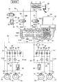
- FIG. 1 is a hydraulic circuit diagram of the vehicle brake device when it is normal.
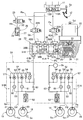
- FIG. 2 is a hydraulic circuit diagram at the time of abnormality corresponding to FIG.
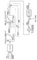
- FIG. 3 is a block diagram of the control system of the electric motor of the slave cylinder.
- FIG. 4 is a diagram for explaining the operation of the accumulator when the brake fluid is discharged.
- the tandem master cylinder 11 includes rear and front hydraulic chambers 13 ⁇ / b> A and 13 ⁇ / b> B that output brake hydraulic pressure in accordance with the pedaling force of the driver stepping on the brake pedal 12.
- the pressure chamber 13A is connected to the wheel cylinders 16 and 17 of the disc brake devices 14 and 15 of the left front wheel and the right rear wheel, for example, via the fluid paths Pa, Pb, Pc, Pd, and Pe (first system).
- the partial hydraulic chamber 13B is connected to the wheel cylinders 20 and 21 of the disc brake devices 18 and 19 of the right front wheel and the left rear wheel, for example, via the fluid paths Qa, Qb, Qc, Qd, and Qe (second system).
- a shutoff valve 22A which is a normally open solenoid valve, is disposed between the fluid paths Pa, Pb, and a shutoff valve 22B, which is a normally open solenoid valve, is disposed between the fluid paths Qa, Qb, and the fluid paths Pb, Qb and the fluid path.
- a slave cylinder 23 is disposed between Pc and Qc, and a VSA (vehicle) that also functions as an ABS (anti-lock brake system) device between the liquid paths Pc and Qc and the liquid paths Pd and Pe; Qd and Qe.
- a stability assist device 24 is arranged.
- a stroke simulator 26 is connected to the liquid paths Ra and Rb branched from the liquid path Pa via a reaction force permission valve 25 which is a normally closed solenoid valve.
- the stroke simulator 26 is a cylinder 27 slidably fitted with a piston 29 urged by a spring 28, and a hydraulic chamber 30 formed on the side opposite to the spring 28 of the piston 29 communicates with a liquid path Rb. To do.
- the actuator 31 of the slave cylinder 23 includes an electric motor 32, a drive bevel gear 33 provided on the output shaft thereof, a driven bevel gear 34 meshing with the drive bevel gear 33, and a ball screw mechanism 35 operated by the driven bevel gear 34.
- a rear piston 38A and a front piston 38B which are urged in a backward direction by return springs 37A and 37B, are slidably disposed on the rear and front portions of the cylinder body 36 of the slave cylinder 23, respectively.
- a rear hydraulic chamber 39A and a front hydraulic chamber 39B are defined on the front surface of the front piston 38B.
- the rear hydraulic chamber 39A communicates with the fluid path Pb via the rear input port 40A, communicates with the fluid path Pc via the rear output port 41A, and the front hydraulic chamber 39B communicates with the front input port 40B.
- the fluid channel Qb communicates with the fluid channel Qc via the front output port 41B.
- the structure of the VSA device 24 is well known.
- the first brake actuator 51A for controlling the first system of the disc brake devices 14 and 15 for the left front wheel and the right rear wheel, the disc brake device 18 for the right front wheel and the left rear wheel, A second brake actuator 51B that controls the 19 second system is provided with the same structure.
- first brake actuator 51A of the first system of the disc brake devices 14 and 15 for the left front wheel and the right rear wheel will be described as a representative example.
- the first brake actuator 51A includes a fluid path Pc that communicates with the rear output port 41A of the slave cylinder 23 located on the upstream side, and a fluid path Pd that communicates with the left front wheel and right rear wheel wheel cylinders 16 and 17 located on the downstream side. , Pe.
- the first brake actuator 51A has a common fluid path 52 and a fluid path 53 for the left front wheel and right rear wheel wheel cylinders 16 and 17, and a variable opening disposed between the fluid path Pc and the fluid path 52.
- a regulator valve 54 composed of a normally open solenoid valve, a check valve 55 arranged in parallel to the regulator valve 54 and allowing the brake fluid to flow from the liquid path Pc side to the liquid path 52 side, and a liquid path
- An in-valve 56 formed of a normally-open electromagnetic valve disposed between the liquid passage Pe and the fluid passage Pe, and arranged in parallel to the in-valve 56, allows the brake fluid to flow from the fluid passage Pe side to the fluid passage 52 side.
- a check valve 59 that allows the brake fluid to flow from the liquid passage 52 to the liquid passage 52 side
- an out valve 60 that is a normally closed electromagnetic valve disposed between the liquid passage Pe and the liquid passage 53, and the liquid passage Pd and the liquid passage 53.
- An out valve 61 composed of a normally closed electromagnetic valve disposed between the accumulator 62 connected to the liquid path 53, and disposed between the liquid path 53 and the liquid path 52, and the liquid path 52 and the slave from the liquid path 53 side.
- a check valve 63 that allows the brake fluid to flow to the cylinder 23 side.
- the VSA device 24 of the present embodiment does not include a pump that returns the brake fluid stored in the accumulator 62 to the slave cylinder 23 side, and the accumulator 62 communicates with the slave cylinder 23 via the check valve 63.
- the brake pedal 12 is provided with a stroke sensor Sa that detects the stroke, and a hydraulic pressure sensor Sb that detects a brake hydraulic pressure generated by the slave cylinder 23 in a liquid passage Pc on one inlet side of the VSA device 24.
- a stroke sensor Sa that detects the stroke
- a hydraulic pressure sensor Sb that detects a brake hydraulic pressure generated by the slave cylinder 23 in a liquid passage Pc on one inlet side of the VSA device 24.
- Each of the four wheels is provided with a wheel speed sensor Sc, and the electric motor 32 is provided with a rotation angle sensor Sd for detecting the rotation angle.
- the shut-off valves 22A and 22B made up of normally-open solenoid valves are excited and closed, and the reaction force permission valve 25 made up of normally-closed solenoid valves is excited. Open the valve.
- the stroke sensor Sa detects the depression of the brake pedal 12 by the driver in this state, the electric motor 32 of the slave cylinder 23 is operated and the rear and front pistons 38A and 38B move forward, so that the rear and front hydraulic pressures are increased.
- Brake fluid pressure is generated in the chambers 39A and 39B. This brake hydraulic pressure is transmitted to the wheel cylinders 16, 17; 20, 21 of the disc brake devices 14, 15; 18, 19 via the opened in valves 56, 56; Braking.
- shutoff valves 22A and 22B are closed and the communication between the master cylinder 11 and the slave cylinder 23 is shut off, so that the brake hydraulic pressure generated by the master cylinder 11 is transferred to the disc brake devices 14, 15; It is never transmitted. Therefore, the brake fluid pressure generated in the fluid pressure chamber 13A of the master cylinder 11 is transmitted to the fluid pressure chamber 30 of the stroke simulator 26 through the opened reaction force permission valve 25, and the piston 29 resists the spring 28.
- the stroke of the brake pedal 12 can be allowed and a pseudo pedal reaction force can be generated to eliminate the driver's uncomfortable feeling.
- the target hydraulic pressure is searched using the pedal stroke-hydraulic pressure map from the smaller one of the stroke of the brake pedal 12 and the VSA (ABS) indicated value detected by the stroke sensor Sa. Further, the target stroke of the slave cylinder 23 is retrieved from the target hydraulic pressure using the hydraulic pressure-slave cylinder stroke map, and this target stroke is converted into the target rotation angle of the electric motor 32 of the slave cylinder 23. Then, by controlling the rotation angle of the electric motor 32 so that the deviation between the actual rotation angle of the electric motor 32 and the target rotation angle converges to zero, the hydraulic pressure corresponding to the stroke of the brake pedal 12 is applied to the slave cylinder 23. It can be generated and supplied to the wheel cylinders 16, 17;
- the target stroke of the slave cylinder 23 is corrected by using the deviation between the target hydraulic pressure and the actual hydraulic pressure, so that the actual hydraulic pressure can be accurately followed by the target hydraulic pressure to increase / decrease the VSA control or ABS control.
- the holding action can be performed with high accuracy.
- the brake fluid pressure that operates the VSA device 24 is generated by a pump that is operated by an electric motor.
- the brake fluid pressure that causes the slave cylinder 23 to operate the VSA device 24 is set. appear.
- the regulator valves 54, 54 are demagnetized and opened, the in valves 56, 56; 58, 58 are demagnetized, and the out valves 60, 60; 61, 61 are opened. Demagnetize and close. Therefore, when the driver depresses the brake pedal 12 to perform braking and the slave cylinder 23 operates, the brake hydraulic pressure output from the rear and front output ports 41A and 41B of the slave cylinder 23 is supplied from the regulator valves 54 and 54. The four wheels can be braked by being transmitted to the wheel cylinders 16, 17; 20, 21 via the in-valves 56, 56; 58, 58 in the valve open state.
- the slave cylinder 23 When the VSA device 24 is operated, the slave cylinder 23 is operated in a state where the regulator valves 54 and 54 are demagnetized and opened, and the brake fluid pressure supplied from the slave cylinder 23 is supplied to the in valves 56 and 56 via the regulator valves 54 and 54. To 58, 58. Accordingly, the brake fluid pressure from the slave cylinder 23 is selectively transmitted to the predetermined wheel cylinders 16, 17; 20, 21 via the predetermined in valves 56, 56; Even when the person does not step on the brake pedal 12, the braking force of the four wheels can be individually controlled.
- the in-valves 56, 56; 58 corresponding to the wheel cylinders 16, 17; , 58 are closed and the out valves 60, 60; 61, 61 are opened, so that the brake fluid pressure in the wheel cylinders 16, 17; 20, 21 is released to the accumulators 62, 62.
- the braking force of the four wheels is individually controlled by the first and second brake actuators 51A and 51B, and the turning performance is improved by increasing the braking force of the turning inner wheel, or the braking force of the turning outer wheel is increased.
- Stability performance (direction stability performance) can be improved.
- ABS anti-lock brake system
- the brake fluid pressure from the rear output port 41A of the slave cylinder 23 is opened by demagnetizing the in-valve 58, so that the wheel cylinder 16 of the left front wheel And the braking force is increased by increasing the pressure to a predetermined pressure.
- the ABS control can be performed to minimize the braking distance while suppressing the lock on the left front wheel by repeating the pressure reduction ⁇ hold ⁇ pressure increase. it can.
- ABS control when the left front wheel wheel cylinder 16 tends to lock has been described above. However, the right rear wheel wheel cylinder 17, the right front wheel wheel cylinder 20, and the left rear wheel wheel cylinder 21 tend to lock.
- the ABS control can be performed in the same manner.
- the brake fluid discharged from the decompressed wheel cylinders 16, 17; 20, 21 is stored in the accumulators 62, 62, and the accumulator Since the pressure reducing capability when the out valves 60, 60; 61, 61 are opened may be reduced because the valves 62, 62 are full, it is necessary to return the brake fluid of the accumulators 62, 62 to the slave cylinder 23 side. . Therefore, the conventional VSA device 24 pumps up the brake fluid of the accumulators 62 and 62 with a pump. However, in this embodiment, since the VSA device 24 does not include a pump, the slave cylinder 23 is caused to exhibit the function of the pump so that the brake fluid in the accumulators 62 and 62 is returned to the slave cylinder 23.
- the brake fluid pressure in the accumulators 62, 62 is transmitted to the rear hydraulic chamber 39A and the front hydraulic chamber 39B of the slave cylinder 23 through the check valves 63, 63, and the return springs 37A, 37B and the electric motor
- the brake fluid in the accumulators 62 and 62 is discharged to the slave cylinder 23.
- a pump is not required to discharge the brake fluid stored in the accumulators 62 and 62, and therefore, the number of parts, weight, and cost can be reduced.
- the slave cylinder 23 is controlled based on a map of “pressure” ⁇ “stroke” so that a piston stroke corresponding to a predetermined brake fluid pressure is generated.
- pressure fluctuation occurs when the in valves 56, 56; 58, 58 are opened after the out valves 60, 60; 61, 61 are opened, the target stroke of the slave cylinder 23 is set in accordance with the pressure fluctuation. If the control is performed so that the target brake fluid pressure is output again after correction, the brake fluid pressure can be maintained without using the regulator valves 54 and 54 and the check valves 55 and 55 (see the chain line frame in FIG. 3). .
- the slave cylinder 23 is operated for a short period of time and the brake fluid of the accumulators 62 and 62 is required. It may be configured to discharge only a minimum amount and then return to ABS control.
- the shutoff valves 22A and 22B made of normally open solenoid valves are automatically opened, and the reaction force permission valve 25 made of normally closed solenoid valves is automatically turned on. Close the valve.
- the brake hydraulic pressure generated in the rear and front hydraulic chambers 13A and 13B of the master cylinder 11 is not absorbed by the stroke simulator 26, and the rear hydraulic chamber 39A and the front hydraulic pressure of the slave cylinder 23 are not absorbed. Passing through the chamber 39B, the wheel cylinders 16, 17; 20, 21 of the disc brake devices 14, 15; 18, 19 of each wheel can be operated to generate a braking force without any trouble.
- the electric brake fluid pressure generating means of the present invention is not limited to the slave cylinder 23 of the embodiment.
- the brake fluid pressure control means of the present invention is not limited to the VSA device 24 of the embodiment, but may be an ABS device that eliminates the regulator valves 54 and 54 from the VSA device 24 and exhibits only the ABS function.
- the in-valve-in valves 56, 56; 58, 58 instead of the regulator valves 54, 54 correspond to the second electromagnetic valve of the present invention.
Landscapes
- Engineering & Computer Science (AREA)
- Physics & Mathematics (AREA)
- Fluid Mechanics (AREA)
- Transportation (AREA)
- Mechanical Engineering (AREA)
- Regulating Braking Force (AREA)
Abstract
Description
17 ホイールシリンダ
20 ホイールシリンダ
21 ホイールシリンダ
23 スレーブシリンダ(電気的ブレーキ液圧発生手段)
24 VSA装置(ブレーキ液圧制御手段)
32 電動モータ
38A ピストン
38B ピストン
54 レギュレータバルブ(第2電磁弁)
56 インバルブ(第2電磁弁)
58 インバルブ(第2電磁弁)
60 アウトバルブ(第1電磁弁)
61 アウトバルブ(第1電磁弁)
62 アキュムレータ
63 チェックバルブ
Sd モータ回転角センサ(判別手段)
Claims (6)
- 各車輪毎に設けられてブレーキ液圧により制動力を発生するホイールシリンダ(16,17;20,21)と、
電動モータ(32)により作動して前記ホイールシリンダ(16,17;20,21)に供給するブレーキ液圧を発生する電気的ブレーキ液圧発生手段(23)と、
前記電気的ブレーキ液圧発生手段(23)および前記ホイールシリンダ(16,17;20,21)間に配置され、前記ホイールシリンダ(16,17;20,21)に供給するブレーキ液圧を個別に制御することで車両挙動を制御するブレーキ液圧制御手段(24)とを備える車両用ブレーキ装置において、
前記ブレーキ液圧制御手段(24)は、
前記ホイールシリンダ(16,17;20,21)および前記電気的ブレーキ液圧発生手段(23)に連通可能なアキュムレータ(62)と、
前記ホイールシリンダ(16,17;20,21)を前記アキュムレータ(62)に接続する液路の連通状態を切り替える第1電磁弁(60,61)と、
前記アキュムレータ(62)から前記電気的ブレーキ液圧発生手段(23)へのブレーキ液の流通のみを許容するチェックバルブ(63)とを備え、
前記アキュムレータ(62)から前記電気的ブレーキ液圧発生手段(23)へのブレーキ液の排出を、前記電気的ブレーキ液圧発生手段(23)の電動モータ(32)の駆動力を低減することで行うことを特徴とする車両用ブレーキ装置。 - 前記チェックバルブ(63)および前記電気的ブレーキ液圧発生手段(23)間を前記ホイールシリンダ(16,17;20,21)に接続する液路の連通状態を切り替える第2電磁弁(54)を備え、
前記ブレーキ液圧制御手段(24)は、前記第1電磁弁(60,61)および前記第2電磁弁(54)の開閉中においてブレーキ液圧を一定に保持することを特徴とする、請求項1に記載の車両用ブレーキ装置。 - 前記電気的ブレーキ液圧発生手段(23)は、前記電動モータ(52)でピストン(38A,38B)を駆動してブレーキ液圧を発生するスレーブシリンダよりなり、前記ピストン(38A,38B)の位置を変化させることでブレーキ液圧を制御することを特徴とする、請求項1に記載の車両用ブレーキ装置。
- 前記ブレーキ液圧制御手段(24)は、前記電気的ブレーキ液圧発生手段(23)および前記ホイールシリンダ(16,17;20,21)間に配置されたインバルブ(56,58)と、前記ホイールシリンダ(16,17;20,21)および前記アキュムレータ(62)間に配置されたアウトバルブ(60,61)とを備え、前記電気的ブレーキ液圧発生手段(23)は、前記インバルブ(56,58)および前記アウトバルブ(60,61)が共に閉弁したときに前記電動モータ(32)の駆動力を低減することを特徴とする、請求項1に記載の車両用ブレーキ装置。
- 前記電気的ブレーキ液圧発生手段(23)は複数の前記ホイールシリンダ(16,17;20,21)に接続され、前記電動モータ(32)の駆動力の低減時には前記複数のホイールシリンダ(16,17;20,21)と前記電気的ブレーキ液圧発生手段(23)との接続を遮断する2電磁弁(54,56,58)を備えることを特徴とする、請求項1に記載の車両用ブレーキ装置。
- 前記電気的ブレーキ液圧発生手段(23)へのブレーキ液圧の排出を判定する判定手段を備えることを特徴とする、請求項1に記載の車両用ブレーキ装置。
Priority Applications (4)
| Application Number | Priority Date | Filing Date | Title |
|---|---|---|---|
| JP2011518560A JP5352669B2 (ja) | 2009-06-12 | 2010-06-09 | 車両用ブレーキ装置 |
| EP10786191.6A EP2441630B1 (en) | 2009-06-12 | 2010-06-09 | Vehicle brake device |
| CN2010800236940A CN102448782A (zh) | 2009-06-12 | 2010-06-09 | 车辆用制动装置 |
| US13/376,207 US8579386B2 (en) | 2009-06-12 | 2010-06-09 | Vehicle brake device |
Applications Claiming Priority (2)
| Application Number | Priority Date | Filing Date | Title |
|---|---|---|---|
| JP2009141605 | 2009-06-12 | ||
| JP2009-141605 | 2009-06-12 |
Publications (1)
| Publication Number | Publication Date |
|---|---|
| WO2010143660A1 true WO2010143660A1 (ja) | 2010-12-16 |
Family
ID=43308915
Family Applications (1)
| Application Number | Title | Priority Date | Filing Date |
|---|---|---|---|
| PCT/JP2010/059769 Ceased WO2010143660A1 (ja) | 2009-06-12 | 2010-06-09 | 車両用ブレーキ装置 |
Country Status (5)
| Country | Link |
|---|---|
| US (1) | US8579386B2 (ja) |
| EP (1) | EP2441630B1 (ja) |
| JP (1) | JP5352669B2 (ja) |
| CN (1) | CN102448782A (ja) |
| WO (1) | WO2010143660A1 (ja) |
Cited By (7)
| Publication number | Priority date | Publication date | Assignee | Title |
|---|---|---|---|---|
| US20120151914A1 (en) * | 2010-12-20 | 2012-06-21 | Honda Motor Co., Ltd. | Vehicle brake system |
| WO2012105526A1 (ja) * | 2011-01-31 | 2012-08-09 | 本田技研工業株式会社 | 車両用ブレーキ装置 |
| JP2016088507A (ja) * | 2014-11-05 | 2016-05-23 | ヒュンダイ・モービス・カンパニー・リミテッド | 車両用回生制動システムの制御方法 |
| WO2016121527A1 (ja) * | 2015-01-30 | 2016-08-04 | 株式会社アドヴィックス | 車両用制動装置 |
| CN106467101A (zh) * | 2015-08-20 | 2017-03-01 | 株式会社万都 | 车辆中的电动控制制动系统及其方法 |
| DE102012025961B4 (de) * | 2012-02-15 | 2025-10-02 | Ipgate Ag | Bremssystem zur Diagnose von Ausfällen |
| DE102012025970B4 (de) * | 2012-02-15 | 2025-10-02 | Ipgate Ag | Bremsbetätigungsvorrichtung |
Families Citing this family (8)
| Publication number | Priority date | Publication date | Assignee | Title |
|---|---|---|---|---|
| DE102011077329A1 (de) * | 2010-07-23 | 2012-01-26 | Continental Teves Ag & Co. Ohg | Verfahren zur Regelung eines elektrohydraulischen Bremssystems sowie elektrohydraulisches Bremssystem |
| WO2012086162A1 (ja) * | 2010-12-23 | 2012-06-28 | 本田技研工業株式会社 | 車両用ブレーキ装置 |
| KR101392840B1 (ko) | 2012-10-31 | 2014-05-09 | 주식회사 만도 | 차량용 전자식 브레이크 시스템 |
| JP6088372B2 (ja) * | 2013-07-04 | 2017-03-01 | 本田技研工業株式会社 | 車両用ブレーキシステム |
| KR101764401B1 (ko) * | 2013-12-27 | 2017-08-14 | 주식회사 만도 | 드래그 저감 기능을 갖는 브레이크 시스템 및 그의 제어방법 |
| JP5892706B2 (ja) | 2013-12-27 | 2016-03-23 | 日信工業株式会社 | ブレーキ液圧発生装置 |
| JP6394562B2 (ja) * | 2015-10-20 | 2018-09-26 | 株式会社アドヴィックス | 車両の制動制御装置 |
| JP6432483B2 (ja) * | 2015-10-20 | 2018-12-05 | 株式会社アドヴィックス | 車両の制動制御装置 |
Citations (2)
| Publication number | Priority date | Publication date | Assignee | Title |
|---|---|---|---|---|
| JP2002255021A (ja) * | 2000-12-28 | 2002-09-11 | Toyota Motor Corp | ブレーキ装置 |
| JP2008110633A (ja) | 2006-10-30 | 2008-05-15 | Honda Motor Co Ltd | ブレーキ装置 |
Family Cites Families (18)
| Publication number | Priority date | Publication date | Assignee | Title |
|---|---|---|---|---|
| US5026126A (en) * | 1989-09-29 | 1991-06-25 | General Motors Corporation | Cam actuated traction control system apparatus and method |
| JPH03279062A (ja) * | 1990-03-28 | 1991-12-10 | Nissan Motor Co Ltd | 流体圧作動系の作動圧制御アクチュエータ |
| DE19538794A1 (de) * | 1995-10-18 | 1997-04-24 | Teves Gmbh Alfred | Elektronisch regelbares Bremsbetätigungssystem |
| US6604795B2 (en) * | 2000-12-28 | 2003-08-12 | Toyota Jidosha Kabushiki Kaisha | Braking system including high-pressure source between master cylinder and brake cylinder |
| JP3969169B2 (ja) | 2002-04-24 | 2007-09-05 | 株式会社アドヴィックス | 車両用電動ブレーキ装置 |
| US8328297B2 (en) * | 2006-06-06 | 2012-12-11 | Honda Motor Co., Ltd. | Brake system |
| JP4999416B2 (ja) * | 2006-10-02 | 2012-08-15 | 本田技研工業株式会社 | ブレーキ装置 |
| JP4503007B2 (ja) * | 2006-12-12 | 2010-07-14 | 本田技研工業株式会社 | ブレーキ装置 |
| JP4792416B2 (ja) * | 2007-03-12 | 2011-10-12 | 本田技研工業株式会社 | ブレーキ装置 |
| JP5123543B2 (ja) * | 2007-03-27 | 2013-01-23 | 本田技研工業株式会社 | ブレーキ装置 |
| DE102007016862A1 (de) * | 2007-04-10 | 2008-10-16 | Robert Bosch Gmbh | Bremssystem für ein Fahrzeug |
| JP2009090932A (ja) * | 2007-10-11 | 2009-04-30 | Honda Motor Co Ltd | 制動装置 |
| JP2009090933A (ja) * | 2007-10-11 | 2009-04-30 | Honda Motor Co Ltd | 制動装置 |
| US8231181B2 (en) * | 2008-01-10 | 2012-07-31 | Honda Motor Co., Ltd. | Brake system |
| JP2010013069A (ja) * | 2008-07-07 | 2010-01-21 | Honda Motor Co Ltd | ブレーキ装置 |
| JP4733754B2 (ja) * | 2008-10-08 | 2011-07-27 | 本田技研工業株式会社 | 車両用ブレーキ装置における引きずり防止方法 |
| JP5484359B2 (ja) * | 2009-02-13 | 2014-05-07 | 本田技研工業株式会社 | 車両用ブレーキ装置の制御方法 |
| WO2010107067A1 (ja) * | 2009-03-19 | 2010-09-23 | 本田技研工業株式会社 | ブレーキ装置 |
-
2010
- 2010-06-09 JP JP2011518560A patent/JP5352669B2/ja not_active Expired - Fee Related
- 2010-06-09 EP EP10786191.6A patent/EP2441630B1/en not_active Not-in-force
- 2010-06-09 CN CN2010800236940A patent/CN102448782A/zh active Pending
- 2010-06-09 WO PCT/JP2010/059769 patent/WO2010143660A1/ja not_active Ceased
- 2010-06-09 US US13/376,207 patent/US8579386B2/en not_active Expired - Fee Related
Patent Citations (2)
| Publication number | Priority date | Publication date | Assignee | Title |
|---|---|---|---|---|
| JP2002255021A (ja) * | 2000-12-28 | 2002-09-11 | Toyota Motor Corp | ブレーキ装置 |
| JP2008110633A (ja) | 2006-10-30 | 2008-05-15 | Honda Motor Co Ltd | ブレーキ装置 |
Non-Patent Citations (1)
| Title |
|---|
| See also references of EP2441630A4 * |
Cited By (17)
| Publication number | Priority date | Publication date | Assignee | Title |
|---|---|---|---|---|
| US8959909B2 (en) | 2010-12-20 | 2015-02-24 | Honda Motor Co., Ltd. | Vehicle brake system |
| CN102529932A (zh) * | 2010-12-20 | 2012-07-04 | 本田技研工业株式会社 | 车辆制动系统 |
| US20120151914A1 (en) * | 2010-12-20 | 2012-06-21 | Honda Motor Co., Ltd. | Vehicle brake system |
| US9358964B2 (en) | 2011-01-31 | 2016-06-07 | Honda Motor Co., Ltd. | Brake device for vehicle |
| JP5734319B2 (ja) * | 2011-01-31 | 2015-06-17 | 本田技研工業株式会社 | 車両用ブレーキ装置 |
| CN103328286B (zh) * | 2011-01-31 | 2016-01-20 | 本田技研工业株式会社 | 车辆用制动装置 |
| WO2012105526A1 (ja) * | 2011-01-31 | 2012-08-09 | 本田技研工業株式会社 | 車両用ブレーキ装置 |
| CN103328286A (zh) * | 2011-01-31 | 2013-09-25 | 本田技研工业株式会社 | 车辆用制动装置 |
| DE102012025970B4 (de) * | 2012-02-15 | 2025-10-02 | Ipgate Ag | Bremsbetätigungsvorrichtung |
| DE102012025961B4 (de) * | 2012-02-15 | 2025-10-02 | Ipgate Ag | Bremssystem zur Diagnose von Ausfällen |
| US10076961B2 (en) | 2014-11-05 | 2018-09-18 | Hyundai Mobis Co., Ltd. | Method for controlling regenerative brake system for vehicle |
| JP2016088507A (ja) * | 2014-11-05 | 2016-05-23 | ヒュンダイ・モービス・カンパニー・リミテッド | 車両用回生制動システムの制御方法 |
| JP2016141184A (ja) * | 2015-01-30 | 2016-08-08 | 株式会社アドヴィックス | 車両用制動装置 |
| US10407036B2 (en) | 2015-01-30 | 2019-09-10 | Advics Co., Ltd. | Vehicle brake device |
| WO2016121527A1 (ja) * | 2015-01-30 | 2016-08-04 | 株式会社アドヴィックス | 車両用制動装置 |
| CN106467101B (zh) * | 2015-08-20 | 2019-04-12 | 株式会社万都 | 车辆中的电动控制制动系统及其方法 |
| CN106467101A (zh) * | 2015-08-20 | 2017-03-01 | 株式会社万都 | 车辆中的电动控制制动系统及其方法 |
Also Published As
| Publication number | Publication date |
|---|---|
| EP2441630B1 (en) | 2014-05-07 |
| US20120145494A1 (en) | 2012-06-14 |
| EP2441630A4 (en) | 2012-10-31 |
| EP2441630A1 (en) | 2012-04-18 |
| JP5352669B2 (ja) | 2013-11-27 |
| US8579386B2 (en) | 2013-11-12 |
| CN102448782A (zh) | 2012-05-09 |
| JPWO2010143660A1 (ja) | 2012-11-29 |
Similar Documents
| Publication | Publication Date | Title |
|---|---|---|
| JP5352669B2 (ja) | 車両用ブレーキ装置 | |
| JP5220827B2 (ja) | 車両用ブレーキ装置 | |
| JP5352602B2 (ja) | 車両用ブレーキ装置 | |
| JP5123972B2 (ja) | 車両用ブレーキ装置および車両用ブレーキ装置の制御方法 | |
| JP4832460B2 (ja) | ブレーキ装置 | |
| JP5204250B2 (ja) | 車両用ブレーキ装置 | |
| JP5484359B2 (ja) | 車両用ブレーキ装置の制御方法 | |
| JP5892706B2 (ja) | ブレーキ液圧発生装置 | |
| JP4801823B2 (ja) | 液圧発生用電動シリンダにおける初期位置設定方法 | |
| JP5389900B2 (ja) | ブレーキ装置におけるスレーブシリンダの固着解消方法 | |
| JP4950149B2 (ja) | ブレーキ装置 | |
| JP6245696B2 (ja) | ブレーキ液圧発生装置 | |
| JP5107857B2 (ja) | 車両用ブレーキ装置 | |
| JP5049939B2 (ja) | 車両用ブレーキ装置 | |
| JP4717779B2 (ja) | ブレーキ装置 | |
| JP2012086687A (ja) | 車両用ブレーキ装置および車両用ブレーキ装置のエア抜き方法 | |
| JP2012176745A (ja) | 車両用ブレーキ装置 | |
| JP6029281B2 (ja) | 車両用ブレーキ装置 | |
| JP5236961B2 (ja) | ブレーキ装置 |
Legal Events
| Date | Code | Title | Description |
|---|---|---|---|
| WWE | Wipo information: entry into national phase |
Ref document number: 201080023694.0 Country of ref document: CN |
|
| 121 | Ep: the epo has been informed by wipo that ep was designated in this application |
Ref document number: 10786191 Country of ref document: EP Kind code of ref document: A1 |
|
| ENP | Entry into the national phase |
Ref document number: 2011518560 Country of ref document: JP Kind code of ref document: A |
|
| WWE | Wipo information: entry into national phase |
Ref document number: 2010786191 Country of ref document: EP |
|
| NENP | Non-entry into the national phase |
Ref country code: DE |
|
| WWE | Wipo information: entry into national phase |
Ref document number: 13376207 Country of ref document: US |