車両用ブレーキ装置Brake device for vehicle
本発明は、各車輪毎に設けられてブレーキ液圧により制動力を発生するホイールシリンダと、電動モータにより作動して前記ホイールシリンダに供給するブレーキ液圧を発生する電気的ブレーキ液圧発生手段と、前記電気的ブレーキ液圧発生手段および前記ホイールシリンダ間に配置され、前記ホイールシリンダに供給するブレーキ液圧を個別に制御することで車両挙動を制御するブレーキ液圧制御手段とを備える車両用ブレーキ装置に関する。
The present invention includes a wheel cylinder that is provided for each wheel and generates a braking force by a brake fluid pressure, and an electric brake fluid pressure generating means that operates by an electric motor to generate a brake fluid pressure that is supplied to the wheel cylinder. And a brake fluid pressure control means that is disposed between the electric brake fluid pressure generating means and the wheel cylinder and controls the vehicle behavior by individually controlling the brake fluid pressure supplied to the wheel cylinder. Relates to the device.
かかる車両用ブレーキ装置は、下記特許文献1により公知である。
Such a vehicle brake device is known from Patent Document 1 below.
この車両用ブレーキ装置は、スレーブシリンダとホイールシリンダとの間に、車輪のロックを抑制して制動距離を短縮するためのABS(アンチロック・ブレーキ・システム)装置を備えており、このABS装置は、ホイールシリンダへのブレーキ液の供給を制御するインバルブと、ホイールシリンダからのブレーキ液の排出を制御するアウトバルブと、ホイールシリンダから排出されたブレーキ液を一時的に貯留するアキュムレータと、アキュムレータに貯留されたブレーキ液を排出するためのポンプ等で構成される。
日本特開2008-110633号公報
This vehicle brake device is provided with an ABS (anti-lock brake system) device between the slave cylinder and the wheel cylinder for suppressing the lock of the wheel and shortening the braking distance. , An in-valve that controls the supply of brake fluid to the wheel cylinder, an out-valve that controls the discharge of brake fluid from the wheel cylinder, an accumulator that temporarily stores brake fluid discharged from the wheel cylinder, and an accumulator A pump for discharging the brake fluid.
Japanese Unexamined Patent Publication No. 2008-110633
ところで、上記従来のものは、アキュムレータに貯留されたブレーキ液を排出するためのポンプを必要とするため、そのポンプの分だけ部品点数、重量、コストが増加する問題があった。
By the way, since the above conventional one requires a pump for discharging the brake fluid stored in the accumulator, there is a problem that the number of parts, weight, and cost increase by the amount of the pump.
本発明は前述の事情に鑑みてなされたもので、車両用ブレーキ装置のブレーキ液圧制御手段のアキュムレータからのブレーキ液の排出を、ポンプを必要とせずに行えるようにすることを目的とする。
The present invention has been made in view of the above-described circumstances, and an object thereof is to allow the brake fluid to be discharged from the accumulator of the brake fluid pressure control means of the vehicle brake device without requiring a pump.
上記目的を達成するために、本発明によれば、各車輪毎に設けられてブレーキ液圧により制動力を発生するホイールシリンダと、電動モータにより作動して前記ホイールシリンダに供給するブレーキ液圧を発生する電気的ブレーキ液圧発生手段と、前記電気的ブレーキ液圧発生手段および前記ホイールシリンダ間に配置され、前記ホイールシリンダに供給するブレーキ液圧を個別に制御することで車両挙動を制御するブレーキ液圧制御手段とを備える車両用ブレーキ装置において、前記ブレーキ液圧制御手段は、前記ホイールシリンダおよび前記電気的ブレーキ液圧発生手段に連通可能なアキュムレータと、前記ホイールシリンダを前記アキュムレータに接続する液路の連通状態を切り替える第1電磁弁と、前記アキュムレータから前記電気的ブレーキ液圧発生手段へのブレーキ液の流通のみを許容するチェックバルブとを備え、前記アキュムレータから前記電気的ブレーキ液圧発生手段へのブレーキ液の排出を、前記電気的ブレーキ液圧発生手段の電動モータの駆動力を低減することで行うことを第1の特徴とする車両用ブレーキ装置が提案される。
In order to achieve the above object, according to the present invention, a wheel cylinder that is provided for each wheel and generates a braking force by a brake fluid pressure, and a brake fluid pressure that is operated by an electric motor and is supplied to the wheel cylinder are provided. Electric brake fluid pressure generating means that generates, and a brake that is disposed between the electric brake fluid pressure generating means and the wheel cylinder, and controls the vehicle behavior by individually controlling the brake fluid pressure supplied to the wheel cylinder. In the vehicular brake device including hydraulic pressure control means, the brake hydraulic pressure control means includes an accumulator capable of communicating with the wheel cylinder and the electric brake hydraulic pressure generating means, and a fluid that connects the wheel cylinder to the accumulator. A first solenoid valve for switching a communication state of the road, and the electric power from the accumulator. A check valve that allows only the brake fluid to flow to the mechanical brake fluid pressure generating means, and discharging the brake fluid from the accumulator to the electric brake fluid pressure generating means A vehicular brake device having a first feature of performing by reducing the driving force of the electric motor is proposed.
また本発明によれば、前記第1の特徴に加えて、前記チェックバルブおよび前記電気的ブレーキ液圧発生手段間を前記ホイールシリンダに接続する液路の連通状態を切り替える第2電磁弁を備え、前記ブレーキ液圧制御手段は、前記第1電磁弁および前記第2電磁弁の開閉中においてブレーキ液圧を一定に保持することを第2の特徴とする車両用ブレーキ装置が提案される。
According to the invention, in addition to the first feature, the second solenoid valve for switching a communication state of a fluid path connecting the wheel and the check brake and the electric brake fluid pressure generating means to the wheel cylinder, There is proposed a vehicle brake device characterized in that the brake fluid pressure control means keeps the brake fluid pressure constant during opening and closing of the first solenoid valve and the second solenoid valve.
また本発明によれば、前記第1の特徴に加えて、前記電気的ブレーキ液圧発生手段は、前記電動モータでピストンを駆動してブレーキ液圧を発生するスレーブシリンダよりなり、前記ピストンの位置を変化させることでブレーキ液圧を制御することを第3の特徴とする車両用ブレーキ装置が提案される。
According to the invention, in addition to the first feature, the electric brake fluid pressure generating means comprises a slave cylinder that generates a brake fluid pressure by driving a piston with the electric motor, and the position of the piston A vehicular brake device having a third feature of controlling the brake fluid pressure by changing the pressure is proposed.
また本発明によれば、前記第1の特徴に加えて、前記ブレーキ液圧制御手段は、前記電気的ブレーキ液圧発生手段および前記ホイールシリンダ間に配置されたインバルブと、前記ホイールシリンダおよび前記アキュムレータ間に配置されたアウトバルブとを備え、前記電気的ブレーキ液圧発生手段は、前記インバルブおよび前記アウトバルブが共に閉弁したときに前記電動モータの駆動力を低減することを第4の特徴とする車両用ブレーキ装置が提案される。
According to the invention, in addition to the first feature, the brake fluid pressure control means includes an in-valve disposed between the electric brake fluid pressure generating means and the wheel cylinder, the wheel cylinder and the accumulator. A fourth feature in that the electric brake fluid pressure generating means reduces the driving force of the electric motor when both the in-valve and the out-valve are closed. A vehicle brake device is proposed.
また本発明によれば、前記第1の特徴に加えて、前記電気的ブレーキ液圧発生手段は複数の前記ホイールシリンダに接続され、前記電動モータの駆動力の低減時には前記複数のホイールシリンダと前記電気的ブレーキ液圧発生手段との接続を遮断する第2電磁弁を備えることを第5の特徴とする車両用ブレーキ装置が提案される。
According to the invention, in addition to the first feature, the electric brake fluid pressure generating means is connected to the plurality of wheel cylinders, and when the driving force of the electric motor is reduced, the plurality of wheel cylinders and the A vehicular brake device having a fifth characteristic is provided, which includes a second electromagnetic valve that cuts off the connection with the electric brake fluid pressure generating means.
また本発明によれば、前記第1の特徴に加えて、前記電気的ブレーキ液圧発生手段へのブレーキ液圧の排出を判定する判定手段を備えることを第6の特徴とする車両用ブレーキ装置が提案される。
According to the present invention, in addition to the first feature, the vehicle brake device according to the sixth feature further comprises determination means for judging discharge of brake fluid pressure to the electric brake fluid pressure generating means. Is proposed.
尚、実施の形態のスレーブシリンダ23は本発明の電気的ブレーキ液圧発生手段に対応し、実施の形態のVSA装置24は本発明のブレーキ液圧制御手段に対応し、実施の形態のレギュレータバルブ54およびインバルブ56,58は本発明の第2電磁弁に対応し、実施の形態のアウトバルブ60,61は本発明の第1電磁弁に対応し、実施の形態のモータ電流センサSdは本発明の判別手段に対応する。
The slave cylinder 23 of the embodiment corresponds to the electric brake fluid pressure generating means of the present invention, and the VSA device 24 of the embodiment corresponds to the brake fluid pressure control means of the present invention, and the regulator valve of the embodiment. 54 and in valves 56 and 58 correspond to the second solenoid valve of the present invention, the out valves 60 and 61 of the embodiment correspond to the first solenoid valve of the present invention, and the motor current sensor Sd of the embodiment corresponds to the present invention. Corresponds to the discriminating means.
本発明の第1の特徴によれば、電気的ブレーキ液圧発生手段からホイールシリンダに供給するブレーキ液圧を個別に制御することで車両挙動を制御するブレーキ液圧制御手段が、ホイールシリンダおよび電気的ブレーキ液圧発生手段に連通可能なアキュムレータと、ホイールシリンダをアキュムレータに接続する液路の連通状態を切り替える第1電磁弁と、アキュムレータから電気的ブレーキ液圧発生手段へのブレーキ液の流通のみを許容するチェックバルブとを備えており、電気的ブレーキ液圧発生手段の電動モータの駆動力を低減することでアキュムレータから電気的ブレーキ液圧発生手段へのブレーキ液の排出を行うので、特別のポンプが不要になって部品点数、重量およびコストを削減することができる。
According to the first aspect of the present invention, the brake hydraulic pressure control means for controlling the vehicle behavior by individually controlling the brake hydraulic pressure supplied from the electric brake hydraulic pressure generating means to the wheel cylinder includes the wheel cylinder and the electric An accumulator capable of communicating with the mechanical brake fluid pressure generating means, a first solenoid valve for switching the communication state of the fluid path connecting the wheel cylinder to the accumulator, and only the flow of the brake fluid from the accumulator to the electrical brake fluid pressure generating means And a check valve that allows the brake fluid to be discharged from the accumulator to the electric brake fluid pressure generating means by reducing the driving force of the electric motor of the electric brake fluid pressure generating means. The number of parts, weight and cost can be reduced.
また本発明の第2の特徴によれば、チェックバルブおよび電気的ブレーキ液圧発生手段間をホイールシリンダに接続する液路の連通状態を切り替える第2電磁弁を備え、ブレーキ液圧制御手段は、第1電磁弁および第2電磁弁の開閉中においてブレーキ液圧を一定に保持するので、VSA制御あるいはABS制御における増圧、減圧および保持作用を精度良く行うことができる。
According to the second aspect of the present invention, the brake fluid pressure control means includes a second solenoid valve that switches a communication state of a fluid path that connects the check valve and the electric brake fluid pressure generating means to the wheel cylinder. Since the brake fluid pressure is kept constant during opening and closing of the first solenoid valve and the second solenoid valve, it is possible to accurately perform the pressure increase, pressure reduction and holding actions in the VSA control or ABS control.
また本発明の第3の特徴によれば、電気的ブレーキ液圧発生手段は、電動モータでピストンを駆動してブレーキ液圧を発生するスレーブシリンダよりなり、ピストンの位置を変化させることでブレーキ液圧を制御するので、所望のブレーキ液圧を脈動なく高い精度で発生させることができる。
According to a third aspect of the present invention, the electric brake fluid pressure generating means comprises a slave cylinder that generates a brake fluid pressure by driving a piston with an electric motor, and the brake fluid is changed by changing the position of the piston. Since the pressure is controlled, a desired brake fluid pressure can be generated with high accuracy without pulsation.
また本発明の第4の特徴によれば、ブレーキ液圧制御手段は、電気的ブレーキ液圧発生手段およびホイールシリンダ間に配置されたインバルブと、ホイールシリンダおよびアキュムレータ間に配置されたアウトバルブとを備えるので、各ホイールシリンダのブレーキ液圧を個別に制御してVSA機能やABS機能を発揮させることができる。また電気的ブレーキ液圧発生手段は、インバルブおよびアウトバルブが共に閉弁したときに電動モータの駆動力を低減するので、ホイールシリンダのブレーキ液圧に影響を及ぼすことなくアキュムレータを減圧することができる。
According to a fourth aspect of the present invention, the brake hydraulic pressure control means includes an in-valve arranged between the electric brake hydraulic pressure generating means and the wheel cylinder, and an out valve arranged between the wheel cylinder and the accumulator. Therefore, the brake fluid pressure of each wheel cylinder can be individually controlled to exhibit the VSA function and the ABS function. Further, the electric brake fluid pressure generating means reduces the driving force of the electric motor when both the in-valve and the out-valve are closed, so that the accumulator can be decompressed without affecting the brake fluid pressure of the wheel cylinder. .
また本発明の第5の特徴によれば、電気的ブレーキ液圧発生手段は複数のホイールシリンダに接続され、電動モータの駆動力の低減時には複数のホイールシリンダと電気的ブレーキ液圧発生手段との接続を第2電磁弁で遮断するので、電気的ブレーキ液圧発生手段が発生する負圧をアキュムレータに確実に作用させて該アキュムレータを減圧することができる。
According to the fifth aspect of the present invention, the electric brake fluid pressure generating means is connected to the plurality of wheel cylinders, and when the driving force of the electric motor is reduced, the plurality of wheel cylinders and the electric brake fluid pressure generating means are Since the connection is interrupted by the second electromagnetic valve, the accumulator can be decompressed by reliably applying the negative pressure generated by the electric brake fluid pressure generating means to the accumulator.
また本発明の第6の特徴によれば、電気的ブレーキ液圧発生手段へのブレーキ液圧の排出を判定する判定手段を備えるので、アキュムレータの減圧が行われたことを確実に判定することができる。
According to the sixth aspect of the present invention, since the determination means for determining the discharge of the brake fluid pressure to the electric brake fluid pressure generating means is provided, it is possible to reliably determine that the accumulator has been depressurized. it can.
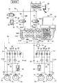
図1は車両用ブレーキ装置の正常時の液圧回路図である。(第1の実施の形態)FIG. 1 is a hydraulic circuit diagram of the vehicle brake device when it is normal. (First embodiment)
図2は図1に対応する異常時の液圧回路図である。(第1の実施の形態)FIG. 2 is a hydraulic circuit diagram at the time of abnormality corresponding to FIG. (First embodiment)
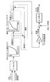
図3はスレーブシリンダの電動モータの制御系のブロック図である。(第1の実施の形態)FIG. 3 is a block diagram of the control system of the electric motor of the slave cylinder. (First embodiment)
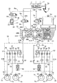
図4はアキュムレータのブレーキ液の排出時の作用説明図である。(第1の実施の形態)FIG. 4 is a diagram for explaining the operation of the accumulator when the brake fluid is discharged. (First embodiment)
16 ホイールシリンダ
17 ホイールシリンダ
20 ホイールシリンダ
21 ホイールシリンダ
23 スレーブシリンダ(電気的ブレーキ液圧発生手段)
24 VSA装置(ブレーキ液圧制御手段)
32 電動モータ
38A ピストン
38B ピストン
54 レギュレータバルブ(第2電磁弁)
56 インバルブ(第2電磁弁)
58 インバルブ(第2電磁弁)
60 アウトバルブ(第1電磁弁)
61 アウトバルブ(第1電磁弁)
62 アキュムレータ
63 チェックバルブ
Sd モータ回転角センサ(判別手段)
16 Wheel cylinder 17 Wheel cylinder 20 Wheel cylinder 21 Wheel cylinder 23 Slave cylinder (electric brake hydraulic pressure generating means)
24 VSA device (brake hydraulic pressure control means)
32 Electric motor 38A Piston 38B Piston 54 Regulator valve (second electromagnetic valve)
56 In-valve (second solenoid valve)
58 In-valve (second solenoid valve)
60 Out valve (first solenoid valve)
61 Out valve (first solenoid valve)
62 Accumulator 63 Check valve Sd Motor rotation angle sensor (discriminating means)
以下、図1~図4に基づいて本発明の実施の形態を説明する。
Hereinafter, embodiments of the present invention will be described with reference to FIGS.
第1の実施の形態First embodiment
図1に示すように、タンデム型のマスタシリンダ11は、運転者がブレーキペダル12を踏む踏力に応じたブレーキ液圧を出力する後部および前部液圧室13A,13Bを備えており、後部液圧室13Aは液路Pa,Pb,Pc,Pd,Pe(第1系統)を介して例えば左前輪および右後輪のディスクブレーキ装置14,15のホイールシリンダ16,17に接続されるとともに、前部液圧室13Bは液路Qa,Qb,Qc,Qd,Qe(第2系統)を介して例えば右前輪および左後輪のディスクブレーキ装置18,19のホイールシリンダ20,21に接続される。
As shown in FIG. 1, the tandem master cylinder 11 includes rear and front hydraulic chambers 13 </ b> A and 13 </ b> B that output brake hydraulic pressure in accordance with the pedaling force of the driver stepping on the brake pedal 12. The pressure chamber 13A is connected to the wheel cylinders 16 and 17 of the disc brake devices 14 and 15 of the left front wheel and the right rear wheel, for example, via the fluid paths Pa, Pb, Pc, Pd, and Pe (first system). The partial hydraulic chamber 13B is connected to the wheel cylinders 20 and 21 of the disc brake devices 18 and 19 of the right front wheel and the left rear wheel, for example, via the fluid paths Qa, Qb, Qc, Qd, and Qe (second system).
液路Pa,Pb間に常開型電磁弁である遮断弁22Aが配置され、液路Qa,Qb間に常開型電磁弁である遮断弁22Bが配置され、液路Pb,Qbと液路Pc,Qcとの間にスレーブシリンダ23が配置され、液路Pc,Qcと液路Pd,Pe;Qd,Qeとの間にABS(アンチロック・ブレーキ・システム)装置の機能を兼ねるVSA(ビークル・スタビリティ・アシスト)装置24が配置される。
A shutoff valve 22A, which is a normally open solenoid valve, is disposed between the fluid paths Pa, Pb, and a shutoff valve 22B, which is a normally open solenoid valve, is disposed between the fluid paths Qa, Qb, and the fluid paths Pb, Qb and the fluid path. A slave cylinder 23 is disposed between Pc and Qc, and a VSA (vehicle) that also functions as an ABS (anti-lock brake system) device between the liquid paths Pc and Qc and the liquid paths Pd and Pe; Qd and Qe. A stability assist device 24 is arranged.
液路Paから分岐する液路Ra,Rbには、常閉型電磁弁である反力許可弁25を介してストロークシミュレータ26が接続される。ストロークシミュレータ26は、シリンダ27にスプリング28で付勢されたピストン29を摺動自在に嵌合させたもので、ピストン29の反スプリング28側に形成された液圧室30が液路Rbに連通する。
A stroke simulator 26 is connected to the liquid paths Ra and Rb branched from the liquid path Pa via a reaction force permission valve 25 which is a normally closed solenoid valve. The stroke simulator 26 is a cylinder 27 slidably fitted with a piston 29 urged by a spring 28, and a hydraulic chamber 30 formed on the side opposite to the spring 28 of the piston 29 communicates with a liquid path Rb. To do.
スレーブシリンダ23のアクチュエータ31は、電動モータ32と、その出力軸に設けた駆動ベベルギヤ33と、駆動ベベルギヤ33に噛合する従動ベベルギヤ34と、従動ベベルギヤ34により作動するボールねじ機構35とを備える。
The actuator 31 of the slave cylinder 23 includes an electric motor 32, a drive bevel gear 33 provided on the output shaft thereof, a driven bevel gear 34 meshing with the drive bevel gear 33, and a ball screw mechanism 35 operated by the driven bevel gear 34.
スレーブシリンダ23のシリンダ本体36の後部および前部に、それぞれリターンスプリング37A,37Bで後退方向に付勢された後部ピストン38Aおよび前部ピストン38Bが摺動自在に配置されており、後部ピストン38Aおよび前部ピストン38Bの前面にそれぞれ後部液圧室39Aおよび前部液圧室39Bが区画される。
A rear piston 38A and a front piston 38B, which are urged in a backward direction by return springs 37A and 37B, are slidably disposed on the rear and front portions of the cylinder body 36 of the slave cylinder 23, respectively. A rear hydraulic chamber 39A and a front hydraulic chamber 39B are defined on the front surface of the front piston 38B.
後部液圧室39Aは後部入力ポート40Aを介して液路Pbに連通するとともに、後部出力ポート41Aを介して液路Pcに連通し、また前部液圧室39Bは前部入力ポート40Bを介して液路Qbに連通するとともに、前部出力ポート41Bを介して液路Qcに連通する。
The rear hydraulic chamber 39A communicates with the fluid path Pb via the rear input port 40A, communicates with the fluid path Pc via the rear output port 41A, and the front hydraulic chamber 39B communicates with the front input port 40B. The fluid channel Qb communicates with the fluid channel Qc via the front output port 41B.
しかして、図1において、電動モータ32を一方向に駆動すると、駆動ベベルギヤ33、従動ベベルギヤ34およびボールねじ機構35を介して後部および前部ピストン38A,38Bが前進して後部および前部液圧室39A,39Bにブレーキ液圧を発生させ、そのブレーキ液圧を後部および前部出力ポート41A,41Bを介して液路Pc,Qcに出力することができる。
1, when the electric motor 32 is driven in one direction, the rear and front pistons 38A and 38B move forward via the drive bevel gear 33, the driven bevel gear 34, and the ball screw mechanism 35, and the rear and front hydraulic pressures. Brake fluid pressure can be generated in the chambers 39A and 39B, and the brake fluid pressure can be output to the fluid paths Pc and Qc via the rear and front output ports 41A and 41B.
VSA装置24の構造は周知のもので、左前輪および右後輪のディスクブレーキ装置14,15の第1系統を制御する第1ブレーキアクチュエータ51Aと、右前輪および左後輪のディスクブレーキ装置18,19の第2系統を制御する第2ブレーキアクチュエータ51Bとに同じ構造のものが設けられる。
The structure of the VSA device 24 is well known. The first brake actuator 51A for controlling the first system of the disc brake devices 14 and 15 for the left front wheel and the right rear wheel, the disc brake device 18 for the right front wheel and the left rear wheel, A second brake actuator 51B that controls the 19 second system is provided with the same structure.
以下、その代表として左前輪および右後輪のディスクブレーキ装置14,15の第1系統の第1ブレーキアクチュエータ51Aについて説明する。
Hereinafter, the first brake actuator 51A of the first system of the disc brake devices 14 and 15 for the left front wheel and the right rear wheel will be described as a representative example.
第1ブレーキアクチュエータ51Aは、上流側に位置するスレーブシリンダ23の後部出力ポート41Aに連なる液路Pcと、下流側に位置する左前輪および右後輪のホイールシリンダ16,17にそれぞれ連なる液路Pd,Peとの間に配置される。
The first brake actuator 51A includes a fluid path Pc that communicates with the rear output port 41A of the slave cylinder 23 located on the upstream side, and a fluid path Pd that communicates with the left front wheel and right rear wheel wheel cylinders 16 and 17 located on the downstream side. , Pe.
第1ブレーキアクチュエータ51Aは左前輪および右後輪のホイールシリンダ16,17に対して共通の液路52および液路53を備えており、液路Pcおよび液路52間に配置された可変開度の常開型電磁弁よりなるレギュレータバルブ54と、このレギュレータバルブ54に対して並列に配置されて液路Pc側から液路52側へのブレーキ液の流通を許容するチェックバルブ55と、液路52および液路Pe間に配置された常開型電磁弁よりなるインバルブ56と、このインバルブ56に対して並列に配置されて液路Pe側から液路52側へのブレーキ液の流通を許容するチェックバルブ57と、液路52および液路Pd間に配置された常開型電磁弁よりなるインバルブ58と、このインバルブ58に対して並列に配置されて液路Pd側から液路52側へのブレーキ液の流通を許容するチェックバルブ59と、液路Peおよび液路53間に配置された常閉型電磁弁よりなるアウトバルブ60と、液路Pdおよび液路53間に配置された常閉型電磁弁よりなるアウトバルブ61と、液路53に接続されたアキュムレータ62と、液路53および液路52間に配置されて液路53側から液路52およびスレーブシリンダ23側へのブレーキ液の流通を許容するチェックバルブ63とを備える。
The first brake actuator 51A has a common fluid path 52 and a fluid path 53 for the left front wheel and right rear wheel wheel cylinders 16 and 17, and a variable opening disposed between the fluid path Pc and the fluid path 52. A regulator valve 54 composed of a normally open solenoid valve, a check valve 55 arranged in parallel to the regulator valve 54 and allowing the brake fluid to flow from the liquid path Pc side to the liquid path 52 side, and a liquid path An in-valve 56 formed of a normally-open electromagnetic valve disposed between the liquid passage Pe and the fluid passage Pe, and arranged in parallel to the in-valve 56, allows the brake fluid to flow from the fluid passage Pe side to the fluid passage 52 side. A check valve 57, an in-valve 58 composed of a normally-open electromagnetic valve disposed between the liquid passage 52 and the liquid passage Pd, and a liquid passage Pd arranged in parallel to the in-valve 58. A check valve 59 that allows the brake fluid to flow from the liquid passage 52 to the liquid passage 52 side, an out valve 60 that is a normally closed electromagnetic valve disposed between the liquid passage Pe and the liquid passage 53, and the liquid passage Pd and the liquid passage 53. An out valve 61 composed of a normally closed electromagnetic valve disposed between the accumulator 62 connected to the liquid path 53, and disposed between the liquid path 53 and the liquid path 52, and the liquid path 52 and the slave from the liquid path 53 side. And a check valve 63 that allows the brake fluid to flow to the cylinder 23 side.
即ち、本実施の形態のVSA装置24は、アキュムレータ62に貯留されたブレーキ液をスレーブシリンダ23側に戻すポンプを備えておらず、アキュムレータ62はチェックバルブ63を介してスレーブシリンダ23に連通する。
That is, the VSA device 24 of the present embodiment does not include a pump that returns the brake fluid stored in the accumulator 62 to the slave cylinder 23 side, and the accumulator 62 communicates with the slave cylinder 23 via the check valve 63.
ブレーキペダル12には、そのストロークを検出するストロークセンサSaが設けられ、VSA装置24の一方の入口側の液路Pcにスレーブシリンダ23が発生するブレーキ液圧を検出する液圧センサSbが設けられ、四輪のそれぞれに車輪速センサSc…が設けられ、電動モータ32には、その回転角を検出する回転角センサSdが設けられる。
The brake pedal 12 is provided with a stroke sensor Sa that detects the stroke, and a hydraulic pressure sensor Sb that detects a brake hydraulic pressure generated by the slave cylinder 23 in a liquid passage Pc on one inlet side of the VSA device 24. Each of the four wheels is provided with a wheel speed sensor Sc, and the electric motor 32 is provided with a rotation angle sensor Sd for detecting the rotation angle.
次に、上記構成を備えた本発明の実施の形態の作用を説明する。
Next, the operation of the embodiment of the present invention having the above configuration will be described.
システムが正常に機能する正常時には、図1に示すように常開型電磁弁よりなる遮断弁22A,22Bが励磁されて閉弁し、常閉型電磁弁よりなる反力許可弁25が励磁されて開弁する。この状態でストロークセンサSaが運転者によるブレーキペダル12の踏み込みを検出すると、スレーブシリンダ23の電動モータ32が作動して後部および前部ピストン38A,38Bが前進することで、後部および前部液圧室39A,39Bにブレーキ液圧が発生する。このブレーキ液圧はVSA装置24の開弁したインバルブ56,56;58,58を介してディスクブレーキ装置14,15;18,19のホイールシリンダ16,17;20,21に伝達され、各車輪を制動する。
When the system functions normally, as shown in FIG. 1, the shut-off valves 22A and 22B made up of normally-open solenoid valves are excited and closed, and the reaction force permission valve 25 made up of normally-closed solenoid valves is excited. Open the valve. When the stroke sensor Sa detects the depression of the brake pedal 12 by the driver in this state, the electric motor 32 of the slave cylinder 23 is operated and the rear and front pistons 38A and 38B move forward, so that the rear and front hydraulic pressures are increased. Brake fluid pressure is generated in the chambers 39A and 39B. This brake hydraulic pressure is transmitted to the wheel cylinders 16, 17; 20, 21 of the disc brake devices 14, 15; 18, 19 via the opened in valves 56, 56; Braking.
このとき、遮断弁22A,22Bが閉弁してマスタシリンダ11とスレーブシリンダ23との連通が遮断されるため、マスタシリンダ11が発生したブレーキ液圧はディスクブレーキ装置14,15;18,19に伝達されることはない。よって、マスタシリンダ11の液圧室13Aが発生したブレーキ液圧は開弁した反力許可弁25を介してストロークシミュレータ26の液圧室30に伝達され、そのピストン29をスプリング28に抗して移動させることで、ブレーキペダル12のストロークを許容するとともに擬似的なペダル反力を発生させて運転者の違和感を解消することができる。
At this time, the shutoff valves 22A and 22B are closed and the communication between the master cylinder 11 and the slave cylinder 23 is shut off, so that the brake hydraulic pressure generated by the master cylinder 11 is transferred to the disc brake devices 14, 15; It is never transmitted. Therefore, the brake fluid pressure generated in the fluid pressure chamber 13A of the master cylinder 11 is transmitted to the fluid pressure chamber 30 of the stroke simulator 26 through the opened reaction force permission valve 25, and the piston 29 resists the spring 28. By moving the brake pedal 12, the stroke of the brake pedal 12 can be allowed and a pseudo pedal reaction force can be generated to eliminate the driver's uncomfortable feeling.
このとき、図3に示すように、ストロークセンサSaで検出したブレーキペダル12のストロークおよびVSA(ABS)指示値の何れか小さい方から、ペダルストローク-液圧マップを用いて目標液圧を検索し、更に目標液圧から、液圧-スレーブシリンダストロークマップを用いてスレーブシリンダ23の目標ストロークを検索し、この目標ストロークをスレーブシリンダ23の電動モータ32の目標回転角に変換する。そして電動モータ32の実回転角と前記目標回転角との偏差がゼロに収束するように電動モータ32の回転角を制御することで、ブレーキペダル12のストロークに応じた液圧をスレーブシリンダ23に発生させてホイールシリンダ16,17;20,21に供給することができる。
At this time, as shown in FIG. 3, the target hydraulic pressure is searched using the pedal stroke-hydraulic pressure map from the smaller one of the stroke of the brake pedal 12 and the VSA (ABS) indicated value detected by the stroke sensor Sa. Further, the target stroke of the slave cylinder 23 is retrieved from the target hydraulic pressure using the hydraulic pressure-slave cylinder stroke map, and this target stroke is converted into the target rotation angle of the electric motor 32 of the slave cylinder 23. Then, by controlling the rotation angle of the electric motor 32 so that the deviation between the actual rotation angle of the electric motor 32 and the target rotation angle converges to zero, the hydraulic pressure corresponding to the stroke of the brake pedal 12 is applied to the slave cylinder 23. It can be generated and supplied to the wheel cylinders 16, 17;
またスレーブシリンダ23の目標ストロークは、目標液圧および実液圧の偏差を用いて補正されるので、実液圧を目標液圧に精度良く追従させてVSA制御やABS制御の増圧、減圧および保持作用を精度良く行うことができる。
Further, the target stroke of the slave cylinder 23 is corrected by using the deviation between the target hydraulic pressure and the actual hydraulic pressure, so that the actual hydraulic pressure can be accurately followed by the target hydraulic pressure to increase / decrease the VSA control or ABS control. The holding action can be performed with high accuracy.
次に、図1に基づいてVSA装置24の作用を説明する。
Next, the operation of the VSA device 24 will be described with reference to FIG.
一般的に、VSA装置24を作動させるブレーキ液圧は電動モータで作動するポンプにより発生するが、本実施の形態はポンプを備えていないためスレーブシリンダ23がVSA装置24を作動させるブレーキ液圧を発生する。
In general, the brake fluid pressure that operates the VSA device 24 is generated by a pump that is operated by an electric motor. However, in this embodiment, since the pump is not provided, the brake fluid pressure that causes the slave cylinder 23 to operate the VSA device 24 is set. appear.
VSA装置24が作動していない状態では、レギュレータバルブ54,54が消磁して開弁し、インバルブ56,56;58,58が消磁して開弁し、アウトバルブ60,60;61,61が消磁して閉弁する。従って、運転者が制動を行うべくブレーキペダル12を踏んでスレーブシリンダ23が作動すると、スレーブシリンダ23の後部および前部出力ポート41A,41Bから出力されたブレーキ液圧は、レギュレータバルブ54,54から開弁状態にあるインバルブ56,56;58,58を経てホイールシリンダ16,17;20,21に伝達され、四輪を制動することができる。
When the VSA device 24 is not in operation, the regulator valves 54, 54 are demagnetized and opened, the in valves 56, 56; 58, 58 are demagnetized, and the out valves 60, 60; 61, 61 are opened. Demagnetize and close. Therefore, when the driver depresses the brake pedal 12 to perform braking and the slave cylinder 23 operates, the brake hydraulic pressure output from the rear and front output ports 41A and 41B of the slave cylinder 23 is supplied from the regulator valves 54 and 54. The four wheels can be braked by being transmitted to the wheel cylinders 16, 17; 20, 21 via the in- valves 56, 56; 58, 58 in the valve open state.
VSA装置24の作動時には、レギュレータバルブ54,54を消磁して開弁した状態でスレーブシリンダ23を作動させ、スレーブシリンダ23から供給されたブレーキ液圧をレギュレータバルブ54,54を経てインバルブ56,56;58,58に伝達する。従って、スレーブシリンダ23からのブレーキ液圧を励磁により開弁した所定のインバルブ56,56;58,58を介して所定のホイールシリンダ16,17;20,21に選択的に伝達することで、運転者がブレーキペダル12を踏んでいない状態でも、四輪の制動力を個別に制御することができる。
When the VSA device 24 is operated, the slave cylinder 23 is operated in a state where the regulator valves 54 and 54 are demagnetized and opened, and the brake fluid pressure supplied from the slave cylinder 23 is supplied to the in valves 56 and 56 via the regulator valves 54 and 54. To 58, 58. Accordingly, the brake fluid pressure from the slave cylinder 23 is selectively transmitted to the predetermined wheel cylinders 16, 17; 20, 21 via the predetermined in valves 56, 56; Even when the person does not step on the brake pedal 12, the braking force of the four wheels can be individually controlled.
また上述のようにして制動力を発生した所定のホイールシリンダ16,17;20,21の制動力を解除するには、そのホイールシリンダ16,17;20,21に対応するインバルブ56,56;58,58を閉弁してアウトバルブ60,60;61,61を開弁することで、ホイールシリンダ16,17;20,21のブレーキ液圧をアキュムレータ62,62に逃がせば良い。
In addition, in order to release the braking force of the predetermined wheel cylinders 16, 17; 20, 21 that generated the braking force as described above, the in- valves 56, 56; 58 corresponding to the wheel cylinders 16, 17; , 58 are closed and the out valves 60, 60; 61, 61 are opened, so that the brake fluid pressure in the wheel cylinders 16, 17; 20, 21 is released to the accumulators 62, 62.
これにより、第1、第2ブレーキアクチュエータ51A,51Bにより四輪の制動力を個別に制御し、旋回内輪の制動力を増加させて旋回性能を高めたり、旋回外輪の制動力を増加させて旋回安定性能(方向安定性能)を高めたりすることができる。
As a result, the braking force of the four wheels is individually controlled by the first and second brake actuators 51A and 51B, and the turning performance is improved by increasing the braking force of the turning inner wheel, or the braking force of the turning outer wheel is increased. Stability performance (direction stability performance) can be improved.
次に、VSA装置24を用いたABS(アンチロック・ブレーキ・システム)制御の作用を説明する。
Next, the operation of ABS (anti-lock brake system) control using the VSA device 24 will be described.
運転者がブレーキペダル12を踏んでの制動中に、例えば左前輪が低摩擦係数路を踏んでロック傾向になったことを車輪速センサSc…の出力に基づいて検出した場合には、第1ブレーキアクチュエータ51Aの一方のインバルブ58を励磁して閉弁するとともに、一方のアウトバルブ61を励磁して開弁することで、左前輪のホイールシリンダ16のブレーキ液圧をアキュムレータ62に逃がして所定の圧力まで減圧した後、アウトバルブ61を消磁して閉弁することで、左前輪のホイールシリンダ16のブレーキ液圧を保持する。その結果、左前輪のホイールシリンダ16のロック傾向が解消に向かうと、インバルブ58を消磁して開弁することで、スレーブシリンダ23の後部出力ポート41Aからのブレーキ液圧を左前輪のホイールシリンダ16に供給して所定の圧力まで増圧することで、制動力を増加させる。
When the driver depresses the brake pedal 12 and detects, for example, that the left front wheel is in a locking tendency by stepping on the low friction coefficient road, based on the output of the wheel speed sensor Sc. Exciting one in-valve 58 of the brake actuator 51A and closing it, and exciting and opening one out-valve 61 allow the brake fluid pressure of the wheel cylinder 16 of the left front wheel to escape to the accumulator 62, and a predetermined After the pressure is reduced to the pressure, the brake fluid pressure of the wheel cylinder 16 of the left front wheel is maintained by demagnetizing and closing the out valve 61. As a result, when the locking tendency of the wheel cylinder 16 of the left front wheel is resolved, the brake fluid pressure from the rear output port 41A of the slave cylinder 23 is opened by demagnetizing the in-valve 58, so that the wheel cylinder 16 of the left front wheel And the braking force is increased by increasing the pressure to a predetermined pressure.
この増圧によって左前輪が再びロック傾向になった場合には、前記減圧→保持→増圧を繰り返すことにより、左前輪のロックを抑制しながら制動距離を最小限に抑えるABS制御を行うことができる。
When the left front wheel becomes locked again due to this pressure increase, the ABS control can be performed to minimize the braking distance while suppressing the lock on the left front wheel by repeating the pressure reduction → hold → pressure increase. it can.
以上、左前輪のホイールシリンダ16がロック傾向になったときのABS制御について説明したが、右後輪のホイールシリンダ17、右前輪のホイールシリンダ20、左後輪のホイールシリンダ21がロック傾向になったときのABS制御も同様にして行うことができる。
The ABS control when the left front wheel wheel cylinder 16 tends to lock has been described above. However, the right rear wheel wheel cylinder 17, the right front wheel wheel cylinder 20, and the left rear wheel wheel cylinder 21 tend to lock. The ABS control can be performed in the same manner.
以上のように、VSA装置24がVSA機能あるいはABS機能を発揮する時間が長いとき、減圧されたホイールシリンダ16,17;20,21から排出されたブレーキ液がアキュムレータ62,62に貯留され、アキュムレータ62,62が満杯になってアウトバルブ60,60;61,61の開弁時の減圧能力が低下する可能性があるため、アキュムレータ62,62のブレーキ液をスレーブシリンダ23側に戻す必要がある。そのため、従来のVSA装置24はポンプでアキュムレータ62,62のブレーキ液を汲み上げていた。しかしながら、本実施の形態ではVSA装置24がポンプを備えていないため、スレーブシリンダ23に前記ポンプの機能を発揮させてアキュムレータ62,62のブレーキ液をスレーブシリンダ23に戻すようになっている。
As described above, when the time for which the VSA device 24 performs the VSA function or the ABS function is long, the brake fluid discharged from the decompressed wheel cylinders 16, 17; 20, 21 is stored in the accumulators 62, 62, and the accumulator Since the pressure reducing capability when the out valves 60, 60; 61, 61 are opened may be reduced because the valves 62, 62 are full, it is necessary to return the brake fluid of the accumulators 62, 62 to the slave cylinder 23 side. . Therefore, the conventional VSA device 24 pumps up the brake fluid of the accumulators 62 and 62 with a pump. However, in this embodiment, since the VSA device 24 does not include a pump, the slave cylinder 23 is caused to exhibit the function of the pump so that the brake fluid in the accumulators 62 and 62 is returned to the slave cylinder 23.
即ち、図4に示すように、アウトバルブ60,60;61,61を消磁して閉弁し、レギュレータバルブ54,54を励磁して閉弁した状態で、スレーブシリンダ23の電動モータ32の出力を低下させると、アキュムレータ62,62内のブレーキ液の圧力がチェックバルブ63,63を経てスレーブシリンダ23の後部液圧室39Aおよび前部液圧室39Bに伝達され、リターンスプリング37A,37Bおよび電動モータ32の付勢力に抗して後部ピストン38Aおよび前部ピストン38Bを後退させることで、アキュムレータ62,62のブレーキ液はスレーブシリンダ23に排出される。
That is, as shown in FIG. 4, the output of the electric motor 32 of the slave cylinder 23 with the out valves 60, 60; 61, 61 demagnetized and closed, and the regulator valves 54, 54 excited and closed. Is reduced, the brake fluid pressure in the accumulators 62, 62 is transmitted to the rear hydraulic chamber 39A and the front hydraulic chamber 39B of the slave cylinder 23 through the check valves 63, 63, and the return springs 37A, 37B and the electric motor By retracting the rear piston 38 </ b> A and the front piston 38 </ b> B against the urging force of the motor 32, the brake fluid in the accumulators 62 and 62 is discharged to the slave cylinder 23.
このとき、制動中のホイールシリンダ16,17;20,21のブレーキ液圧は、チェックバルブ55,55および閉弁したレギュレータバルブ54,54に阻止されて減圧されることはない。
At this time, the brake fluid pressure of the wheel cylinders 16, 17; 20, 21 during braking is not blocked by the check valves 55, 55 and the closed regulator valves 54, 54 and is not reduced.
尚、スレーブシリンダ23が作動してアキュムレータ62,62のブレーキ液がスレーブシリンダ23に戻されたことは、スレーブシリンダ23の電動モータ32の回転角を回転角センサSdで監視することで判定することができる。
Note that it is determined by monitoring the rotation angle of the electric motor 32 of the slave cylinder 23 by the rotation angle sensor Sd that the slave cylinder 23 is activated and the brake fluid of the accumulators 62 and 62 is returned to the slave cylinder 23. Can do.
以上のように、本実施の形態によれば、アキュムレータ62,62に貯留されたブレーキ液を排出するためにポンプが不要になるため、部品点数、重量およびコストの削減を図ることができる。
As described above, according to the present embodiment, a pump is not required to discharge the brake fluid stored in the accumulators 62 and 62, and therefore, the number of parts, weight, and cost can be reduced.
ところで、レギュレータバルブ54,54およびチェックバルブ63,63を介さずにスレーブシリンダ23の後部および前部出力ポート41A,41Bが直接複数のホイールシリンダ16,17;20,21に接続されている場合には、一方のインバルブ56,56;58,58が開弁しているとホイールシリンダ16,17;20,21のブレーキ液圧に変動が生じるため、インバルブ56,56;58,58およびアウトバルブ60,60;61,61が全て閉弁してブレーキ液圧が保持されている状態(ABS制御の液圧保持状態)に同期して、スレーブシリンダ23を作動させてアキュムレータ62,62のブレーキ液を排出することが望ましい。
By the way, when the rear and front output ports 41A, 41B of the slave cylinder 23 are directly connected to the plurality of wheel cylinders 16, 17; 20, 21, without passing through the regulator valves 54, 54 and the check valves 63, 63. Since, when one of the in- valves 56, 56; 58, 58 is opened, the brake fluid pressure of the wheel cylinders 16, 17; 20, 21 changes, so the in- valves 56, 56; 58, 58 and the out- valve 60 , 60; 61, 61 are all closed to synchronize with the state in which the brake fluid pressure is retained (the fluid pressure retained state of the ABS control), and the slave cylinder 23 is operated to cause the brake fluid in the accumulators 62, 62 to flow. It is desirable to discharge.
このとき、スレーブシリンダ23は、所定のブレーキ液圧に対応するピストンストロークが生じるように、「圧力」-「ストローク」のマップに基づいて制御される。またアウトバルブ60,60;61,61を開弁した後にインバルブ56,56;58,58を開弁したときに圧力変動を生じる場合には、この圧力変動に応じてスレーブシリンダ23の目標ストロークを補正して再び目標ブレーキ液圧を出力するように制御すれば、レギュレータバルブ54,54およびチェックバルブ55,55を用いずともブレーキ液圧の保持が可能である(図3の鎖線枠内参照)。
At this time, the slave cylinder 23 is controlled based on a map of “pressure” − “stroke” so that a piston stroke corresponding to a predetermined brake fluid pressure is generated. When pressure fluctuation occurs when the in valves 56, 56; 58, 58 are opened after the out valves 60, 60; 61, 61 are opened, the target stroke of the slave cylinder 23 is set in accordance with the pressure fluctuation. If the control is performed so that the target brake fluid pressure is output again after correction, the brake fluid pressure can be maintained without using the regulator valves 54 and 54 and the check valves 55 and 55 (see the chain line frame in FIG. 3). .
またABS制御の減圧時に車輪速の回復量が減少したこと等からアキュムレータ62,62の満杯が判別された場合には、スレーブシリンダ23を短期間だけ作動させてアキュムレータ62,62のブレーキ液を必要最小限だけ排出し、その後にABS制御に復帰するように構成しても良い。
In addition, when it is determined that the accumulators 62 and 62 are full due to a decrease in the recovery speed of the wheel speed when the ABS control is depressurized, the slave cylinder 23 is operated for a short period of time and the brake fluid of the accumulators 62 and 62 is required. It may be configured to discharge only a minimum amount and then return to ABS control.
さて、電源の失陥等によりスレーブシリンダ23が作動不能になると、スレーブシリンダ23が発生するブレーキ液圧に代えて、マスタシリンダ11が発生するブレーキ液圧による制動が行われる。
When the slave cylinder 23 becomes inoperable due to a power failure or the like, braking is performed by the brake fluid pressure generated by the master cylinder 11 instead of the brake fluid pressure generated by the slave cylinder 23.
即ち、電源が失陥すると、図2に示すように、常開型電磁弁よりなる遮断弁22A,22Bは自動的に開弁し、常閉型電磁弁よりなる反力許可弁25は自動的に閉弁する。この状態では、マスタシリンダ11の後部および前部液圧室13A,13Bにおいて発生したブレーキ液圧は、ストロークシミュレータ26に吸収されることなく、スレーブシリンダ23の後部液圧室39Aおよび前部液圧室39Bを通過して各車輪のディスクブレーキ装置14,15;18,19のホイールシリンダ16,17;20,21を作動させ、支障なく制動力を発生させることができる。
That is, when the power supply fails, as shown in FIG. 2, the shutoff valves 22A and 22B made of normally open solenoid valves are automatically opened, and the reaction force permission valve 25 made of normally closed solenoid valves is automatically turned on. Close the valve. In this state, the brake hydraulic pressure generated in the rear and front hydraulic chambers 13A and 13B of the master cylinder 11 is not absorbed by the stroke simulator 26, and the rear hydraulic chamber 39A and the front hydraulic pressure of the slave cylinder 23 are not absorbed. Passing through the chamber 39B, the wheel cylinders 16, 17; 20, 21 of the disc brake devices 14, 15; 18, 19 of each wheel can be operated to generate a braking force without any trouble.
以上、本発明の実施の形態を説明したが、本発明はその要旨を逸脱しない範囲で種々の設計変更を行うことが可能である。
Although the embodiments of the present invention have been described above, various design changes can be made without departing from the scope of the present invention.
例えば、本発明の電気的ブレーキ液圧発生手段は実施の形態のスレーブシリンダ23に限定されるものではない。
For example, the electric brake fluid pressure generating means of the present invention is not limited to the slave cylinder 23 of the embodiment.
また本発明のブレーキ液圧制御手段は実施の形態のVSA装置24に限定されるものではなく、VSA装置24からレギュレータバルブ54,54を廃止してABS機能だけを発揮するABS装置としても良い。この場合、レギュレータバルブ54,54ではなくインバルブインバルブ56,56;58,58が本発明の第2電磁弁に相当する。
Further, the brake fluid pressure control means of the present invention is not limited to the VSA device 24 of the embodiment, but may be an ABS device that eliminates the regulator valves 54 and 54 from the VSA device 24 and exhibits only the ABS function. In this case, the in-valve-in valves 56, 56; 58, 58 instead of the regulator valves 54, 54 correspond to the second electromagnetic valve of the present invention.