WO2010143621A1 - 画像処理装置、画像処理方法及び記憶媒体 - Google Patents
画像処理装置、画像処理方法及び記憶媒体 Download PDFInfo
- Publication number
- WO2010143621A1 WO2010143621A1 PCT/JP2010/059673 JP2010059673W WO2010143621A1 WO 2010143621 A1 WO2010143621 A1 WO 2010143621A1 JP 2010059673 W JP2010059673 W JP 2010059673W WO 2010143621 A1 WO2010143621 A1 WO 2010143621A1
- Authority
- WO
- WIPO (PCT)
- Prior art keywords
- document
- pages
- page
- image processing
- processing apparatus
- Prior art date
- Legal status (The legal status is an assumption and is not a legal conclusion. Google has not performed a legal analysis and makes no representation as to the accuracy of the status listed.)
- Ceased
Links
Images





Classifications
-
- G—PHYSICS
- G06—COMPUTING OR CALCULATING; COUNTING
- G06F—ELECTRIC DIGITAL DATA PROCESSING
- G06F16/00—Information retrieval; Database structures therefor; File system structures therefor
- G06F16/90—Details of database functions independent of the retrieved data types
- G06F16/95—Retrieval from the web
- G06F16/957—Browsing optimisation, e.g. caching or content distillation
- G06F16/9577—Optimising the visualization of content, e.g. distillation of HTML documents
-
- G—PHYSICS
- G06—COMPUTING OR CALCULATING; COUNTING
- G06F—ELECTRIC DIGITAL DATA PROCESSING
- G06F16/00—Information retrieval; Database structures therefor; File system structures therefor
- G06F16/30—Information retrieval; Database structures therefor; File system structures therefor of unstructured textual data
- G06F16/34—Browsing; Visualisation therefor
-
- G—PHYSICS
- G06—COMPUTING OR CALCULATING; COUNTING
- G06F—ELECTRIC DIGITAL DATA PROCESSING
- G06F3/00—Input arrangements for transferring data to be processed into a form capable of being handled by the computer; Output arrangements for transferring data from processing unit to output unit, e.g. interface arrangements
- G06F3/01—Input arrangements or combined input and output arrangements for interaction between user and computer
- G06F3/048—Interaction techniques based on graphical user interfaces [GUI]
- G06F3/0484—Interaction techniques based on graphical user interfaces [GUI] for the control of specific functions or operations, e.g. selecting or manipulating an object, an image or a displayed text element, setting a parameter value or selecting a range
- G06F3/04842—Selection of displayed objects or displayed text elements
-
- G—PHYSICS
- G06—COMPUTING OR CALCULATING; COUNTING
- G06F—ELECTRIC DIGITAL DATA PROCESSING
- G06F3/00—Input arrangements for transferring data to be processed into a form capable of being handled by the computer; Output arrangements for transferring data from processing unit to output unit, e.g. interface arrangements
- G06F3/01—Input arrangements or combined input and output arrangements for interaction between user and computer
- G06F3/048—Interaction techniques based on graphical user interfaces [GUI]
- G06F3/0484—Interaction techniques based on graphical user interfaces [GUI] for the control of specific functions or operations, e.g. selecting or manipulating an object, an image or a displayed text element, setting a parameter value or selecting a range
- G06F3/04845—Interaction techniques based on graphical user interfaces [GUI] for the control of specific functions or operations, e.g. selecting or manipulating an object, an image or a displayed text element, setting a parameter value or selecting a range for image manipulation, e.g. dragging, rotation, expansion or change of colour
-
- G—PHYSICS
- G06—COMPUTING OR CALCULATING; COUNTING
- G06F—ELECTRIC DIGITAL DATA PROCESSING
- G06F40/00—Handling natural language data
- G06F40/10—Text processing
- G06F40/103—Formatting, i.e. changing of presentation of documents
- G06F40/114—Pagination
-
- G—PHYSICS
- G06—COMPUTING OR CALCULATING; COUNTING
- G06F—ELECTRIC DIGITAL DATA PROCESSING
- G06F40/00—Handling natural language data
- G06F40/10—Text processing
- G06F40/12—Use of codes for handling textual entities
- G06F40/14—Tree-structured documents
- G06F40/143—Markup, e.g. Standard Generalized Markup Language [SGML] or Document Type Definition [DTD]
-
- G—PHYSICS
- G06—COMPUTING OR CALCULATING; COUNTING
- G06F—ELECTRIC DIGITAL DATA PROCESSING
- G06F40/00—Handling natural language data
- G06F40/10—Text processing
- G06F40/166—Editing, e.g. inserting or deleting
-
- G—PHYSICS
- G06—COMPUTING OR CALCULATING; COUNTING
- G06T—IMAGE DATA PROCESSING OR GENERATION, IN GENERAL
- G06T11/00—Two-dimensional [2D] image generation
- G06T11/60—Creating or editing images; Combining images with text
-
- H—ELECTRICITY
- H04—ELECTRIC COMMUNICATION TECHNIQUE
- H04N—PICTORIAL COMMUNICATION, e.g. TELEVISION
- H04N1/00—Scanning, transmission or reproduction of documents or the like, e.g. facsimile transmission; Details thereof
- H04N1/387—Composing, repositioning or otherwise geometrically modifying originals
Definitions
- the present invention relates to an image processing apparatus that outputs an image corresponding to a document in which elements are arranged.
- a system for editing a print layout of an image in which text, images, graphics, etc. are mixed is known. Such a system is used in document editing software, drawing software, album software for creating an album with images taken by a digital camera, and the like.
- a user can move, enlarge, and reduce a graphic object in an image by operating a pointing device such as a mouse.
- a pointing device such as a mouse.
- the moved or enlarged object may cross the page boundary, and the drawing software that creates diagrams and graphics can also be moved across pages. Some can be edited.
- Patent Document 1 when an image is laid out in a layout frame set in advance on a spread page, an image of a person or the like is folded so that an area corresponding to the person or the like in the image does not overlap a fold of the page. A technique for shifting from the position is described.
- Patent Document 1 lays out an image in a layout frame that is predetermined for a spread page. Therefore, the user does not edit the image arbitrarily, such as enlargement or movement, and does not perform the layout of the image edited by the user.
- the object when a user edits an object in a page, the object may be arranged at a page break position as a result of the user's arbitrary editing. At this time, if the object is divided at the page break position, it may be difficult for the user to recognize the contents of the divided object.
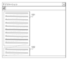
- FIGS. 12A and 12B In the document editing application, when the table is spread between pages, the line of the table is regarded as the same line as the text and a line break is made between pages.
- line breaks between pages in the document editing application will be described with reference to FIGS. 12A and 12B.
- FIG. 12A when characters are filled up to the rear end of the page 1201, a line feed is made on the front end line of the page 1202 which is the next page of the page 1201.
- FIG. 12B even in pages 1203 and 1204 where pages are not continuously arranged up and down, a line feed 1205 from the rear end row of the page 1203 to the front end of the page 1204 is performed.
- the table row is sent to the next page and the table is divided in the same manner as the line feed of the text shown in FIGS. 12A and 12B.
- the table is divided between pages, and thus it may be difficult for the user to recognize the contents of the table.
- the present invention provides an image processing apparatus capable of appropriately arranging and outputting elements in a document.
- the present invention is included in a moving unit that moves an object including at least one element on a document in which the object is arranged, and an object that is moved on the document by the moving unit in response to an instruction from a user.
- An acquisition unit that acquires information indicating a position of the element in the document, and the object based on the information acquired by the acquisition unit when the object is moved to a boundary between two pages by the moving unit.
- detecting means for detecting at least one element corresponding to a position of a break between the two pages, and at least one element detected by the detecting means is arranged on one of the two pages
- Determining means for determining a position where the element is arranged on the document; And having and an output means for elements determined position to output an image corresponding to the arrangement documents by serial determination means
- elements can be appropriately arranged and output in a document.
- FIG. 2 is a block diagram showing a software configuration on a PC 101.
- FIG. It is a figure which shows a GUI screen. It is a figure which shows a GUI screen. It is a figure which shows a print preview screen. It is a figure which shows a print preview screen. It is a figure which shows a print preview screen. It is a figure which shows a print preview screen. It is a figure which shows a print preview screen.
- 3 is a block diagram illustrating a configuration of a print layout unit 206.
- FIG. It is a figure which shows the process sequence of an object edit process.
- 5 is a diagram showing a page layout in a page break coordinate detection unit 503.
- FIG. It is a figure which shows the object 801.
- FIG. 1 is a block diagram showing the configuration of the layout editing apparatus.
- Reference numeral 101 denotes a PC (Personal Computer) as an example of a layout editing apparatus.
- the CPU 102 performs data operations and instructions according to a program, and controls each unit of the PC 101 and connected devices.
- a RAM 103 is a memory used as a temporary storage area, and a ROM 104 is a memory that stores various programs executed by the CPU 102.
- the hard disk 105 records an operating system (OS), a browser, other application software programs, data, and the like. That is, the CPU 102 reads out a program stored in the ROM 104 or the hard disk 105 to the RAM 103 and executes the program using the RAM 103 as a work memory, thereby performing various controls.
- OS operating system
- the USB interface 106 is an interface to which a USB cable is connected, and is an interface for performing data communication with a printer (not shown).
- the communication with the printer may be performed by other than the USB cable, for example, by SCSI or wireless.
- the display device 107 includes a CRT, a liquid crystal display, and a graphic controller, and various displays are performed by display control of the PC 101. For example, a Web page based on a structured document downloaded from a WWW server via the communication interface 110, a print preview image, a graphic user interface (GUI), or the like is displayed.
- GUI graphic user interface
- the mouse 108 and the keyboard 109 are input devices for the user to give various instructions to the PC 101.
- the system bus 111 exchanges data with the CPU 102, RAM 103, ROM 104, hard disk 105, and the like.
- the communication interface 110 is an interface to which a LAN cable is connected, and performs data communication with an external WWW server via a router (not shown) or the Internet. Note that this data communication may be performed wirelessly using, for example, a wireless interface.
- FIG. 2 is a block diagram showing a software configuration on the PC 101. A program that runs on the PC 101 and its data processing configuration will be described below with reference to FIG.
- the browser 201 is an application for displaying a Web page, and downloads a structured document file on a WWW server (not shown) to the hard disk 105 on the PC 101. Then, the Web page is displayed on the display device 107 based on the structured document file.
- the structured document file is described in a structured language such as HTML or XHTML. Specifically, elements constituting the structured document such as text and images are described using tags. Further, another file called Cascading Style Sheet (hereinafter abbreviated as CSS) that specifies the display style of these elements is specified in the structured document.
- CSS Cascading Style Sheet
- FIG. 2 is a block diagram showing a software configuration on the PC 101. Each block shown in FIG. 2 is obtained by classifying programs stored in the ROM 104 or the hard disk 105 by function, and these programs are executed by the CPU 102.
- the structured document printing module 202 is plug-in software called from the browser 201, and the structured document printing module 202 is executed when the user issues a print or print preview instruction to the browser 201.
- the document cutout unit 203 cuts out a part of the structured document.
- the intermediate file creation unit 204 creates an intermediate file of a format such as EMF (Enhanced Metafile) corresponding to the print area cut out by the document cutout unit 203 as a graphic object.
- This intermediate file is stored in the intermediate file storage unit 205.
- This intermediate file holds elements in the Web page as text and images as vector data. Accordingly, when editing such as enlargement is performed on an object displayed based on the intermediate file, deterioration in image quality can be suppressed compared to when editing is performed on image data such as a bitmap.
- the print layout unit 206 lays out the graphic object of the intermediate file to the paper size according to the print settings.
- This print setting includes information such as the paper size, resolution, and printable area, and is acquired from the printer driver 210 via the OS 209.
- the print preview unit 207 causes the display device 107 to display the graphic object laid out by the print layout unit 206 as a print preview.
- the print processing unit 208 executes a drawing process on the printer driver 210 via the OS 209 when the user receives a print start instruction. At this time, the drawing process is executed based on the intermediate file object arranged according to the information indicating the layout by the print layout unit 206.
- the OS 209 provides an API (Application Programming Interface) for the structured document printing module 202 to exchange print setting data from the printer driver 210 and an API for performing drawing processing.
- the OS 209 includes various control software such as a spooler system that manages print jobs and a port monitor that outputs printer commands to a port.
- the printer driver 210 generates print data according to the drawing process executed by the print processing unit 208. The generated print data is converted into a printer command, and the printer command is transmitted to the printer 211 via the OS 209 to cause the printer 211 to print an image on paper.
- 3A and 3B are diagrams showing GUI screens.
- a web page is displayed in the browser 301.
- the clip mode is entered as shown in FIG. 3B, and the web page is displayed with a gray window overlapped.
- a selection area 302 is cut out by the processing of the document cutout unit 203, and the selected area does not overlap with a gray window. The display changes to. In this state, the selection area 302 can be moved / enlarged / reduced.
- the user decides the area to be printed, the user presses the confirm button 303 to end the clip mode. Then, the selection area 302 in the Web page is converted into an EMF file by the intermediate file creation unit 204 and stored in the intermediate file storage unit 205.
- the print preview button 304 shown in FIG. 3B is pressed by the user, a print preview screen is displayed by the processing of the print preview unit 207.
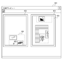
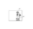
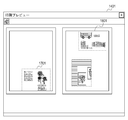
- FIGS. 4A, 4B, 4C, and 4D are diagrams showing a print preview screen.
- pages 402 and 403 are displayed side by side without being continuous.
- the object 404 is an intermediate file in the EMF file format created based on the web page selection area 302 and the object 405 based on the web page selection area 305.
- a plurality of areas may be selected from the same Web page, or a plurality of areas may be selected from a plurality of Web pages.
- FIG. 4B shows the moving object 404.
- the moving object 404 is displayed in, for example, a gray shaded state so that it can be identified that the object is moving.
- the gray shaded state returns to the normal state when the editing operation is confirmed by releasing the mouse button.
- the mouse pointer 406 When the mouse pointer 406 is further dragged downward and the object 404 protrudes from the rear end of the page 402, it is divided into a first page object 410 and a second page object 411 as shown in FIG. 4C. Further, when the mouse pointer 406 is dragged downward and the mouse pointer 406 exceeds the lower end of the page 402, a new page 412 is created as shown in FIG. 4D.
- the object 404 is divided into a first page object 413 and a second page object 414 and displayed on pages 403 and 412 respectively.
- the mouse pointer 409 shown in FIG. 4C exceeds the lower end of the page 402, the page on which the object is arranged does not have to be changed from the state shown in FIG. 4C. Further, when the mouse pointer 409 exceeds the lower end of the page 402, the mouse pointer may be moved to the upper end of the page 403. In other words, the user can move the mouse pointer 409 downward on the page 403 following the operation of moving the mouse pointer 409 downward on the page 402. Therefore, even if the mouse pointer 409 exceeds the lower end of the page 402, the object placed at the upper end of the page 403 can be specified, so that an operation for moving or enlarging the object can be performed continuously across the pages. Can do.
- FIG. 5 is a block diagram showing the configuration of the print layout unit 206.
- FIG. 6 is a diagram showing the processing procedure of the object editing process, and the process in which the print layout unit 206 moves the objects shown in FIGS. 4A to 4D will be described with reference to the flowchart of FIG.
- the editing mode is entered, and the editing instruction unit 501 initializes an event flag (S601) in order to accept an editing instruction from the user (S601). Enter instruction standby state. Then, by checking whether the print button 407 or the end button 408 has been pressed, it is determined whether to end the edit mode (S602). When it is confirmed that the print button 407 or the end button 408 is pressed, the editing mode is ended.
- the type of the mouse event is determined (S603).
- the mouse event detected here is one of button release, button click, and pointer movement.
- a button release event it means the end of editing of the object, so the event flag is initialized and the apparatus enters a state of waiting for an instruction from the user (S604).
- the object acquisition unit 502 acquires the coordinates on the clicked page, and determines whether or not an object is detected at the coordinates (S605). If no object is detected, the process returns to the instruction standby state. On the other hand, when an object is detected, the object acquisition unit 502 acquires the corresponding object from the intermediate file storage unit 205, stores the coordinates on the page of the object and the coordinates on the page of the mouse pointer, and clicks anywhere on the object Is detected (S606).
- the movement flag is set in the event flag (S607), and when the outer periphery of the object is clicked, the enlargement / reduction flag is set in the event flag (S608), and the instruction standby state is returned. .
- the object acquisition unit 502 when the object is moved or enlarged / reduced by the processing of the object acquisition unit 502, the coordinates and size of the object on the page are passed to the page break coordinate detection unit 503, and the process proceeds to the page break coordinate detection processing.
- a detailed description of the method for enlarging / reducing the object 404 is omitted.
- the object has been moved / enlarged / reduced, it returns to the instruction standby state.
- the page break coordinate detection unit 503 detects whether the object 404 overlaps the page break coordinates from the size / coordinates of the object 404 sent from the object acquisition unit 502 (S612).
- FIG. 7 is a diagram showing a page layout in the page break coordinate detection unit 503.
- a document is handled with a layout in which pages are continuous as shown in FIG. That is, pages 402 and 403 are mapped to pages 701 and 702.
- the divided coordinates of the object are calculated from the coordinates / size of the page of the object 404 and the coordinates of the page boundary 703.
- the divided coordinates indicate coordinates divided in the object 404, and the divided coordinates are sent to the object dividing unit 504.
- the object dividing unit 504 divides the object 404 into the first page object 410 and the second page object 411 according to the acquired object dividing coordinates (S613).
- the divided objects are sent to the object placement unit 505 together with their sizes and coordinates.
- the object placement unit 505 places the first page object 410 and the second page object 411 on the page 402 as shown in FIG. 4C (S614), and sends the images indicating the pages 701 and 702 to the print preview unit 207. Then, the print preview unit 207 performs GUI display on the print preview screen 401 (S615).
- FIG. 4D shows a GUI display when the mouse pointer 409 shown in FIG. 4C moves further down from the state of FIG. 4C and exceeds the lower end of the page 402.
- the page break coordinate detection unit 503 and the object division unit 504 divide the object in the same manner as in FIG. 4C, but the pages on which the divided objects are arranged are different.
- the object placement unit 505 places the object 413 serving as the first page object on the page 403 instead of the page 402. Then, the object 414 as the second page object is arranged not on the page 403 but on the page 412 added behind the object. In this way, the layout shown in FIG. 4D is displayed by arranging each page one page later.
- FIG. 9A is a diagram showing a GUI display of the print preview unit 207.
- printable areas 902 and 903 are added to the pages 402 and 403 in the print preview screen 401 described above.
- the printable area indicates an area where printing on a sheet printed by a printer is possible. That is, when printing with a printer, an area is set in which printing cannot be performed on the entire sheet due to factors such as a sheet conveyance error, and printing is possible within the sheet. This differs for each printer to be used and is obtained from the printer driver 210.
- dotted lines indicating the printable areas 902 and 903 are not actually printed, and are displayed on the print preview screen 901 in order to clarify the range.
- the case where the object 404 is moved downward using the mouse pointer 406 as in the above example will be described as an example.
- the editing instruction unit 501 instructs editing of an object in the same manner as in the above example.
- the object acquisition unit 502 performs processing for acquiring the coordinates and size of the object on the page, as in the above-described example.
- the coordinates of the mouse pointer 406 are mapped to the front and rear ends of the printable area 902.
- a case where the mouse pointer 406 exceeds the lower end of the printable area 902 is described as an example, but the same operation is performed at the upper end, the left end, and the right end.
- the pages are handled like the pages 701 and 702 shown in FIG.
- the size of the pages 701 and 702 handled inside is not the size of the pages 402 and 403 but the size of the printable areas 902 and 903.
- the object dividing unit 504 divides the object, and the object arrangement unit 505 arranges the divided object.
- the first page object 904 is arranged in the printable area 902
- the second page object 905 is arranged in the printable area 903.
- the printable area is set for the page size.
- a user-set margin is set for the page size, and a print preview is displayed to show the set margin. It doesn't matter.
- FIG. 10A, FIG. 10B, and FIG. 10C are diagrams showing the relationship between objects and page breaks.
- the area in FIG. 10A is extracted from the Web page displayed by the browser 201 by the document cutout unit 203 and extracted by the intermediate file creation unit 204 as an intermediate file in the EMF file format.
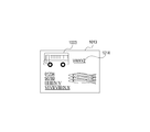
- the object 1001 includes elements 1002, 1003, 1004, 1005, and 1006 (elements 1002, 1003, and 1004 are image elements, and elements 1005 and 1006 are text elements). Then, the object acquisition unit 502 acquires the object 1001, and the page break coordinate detection unit 503 sets the first object division coordinates 1007 in the object 1001.
- the object dividing unit 504 first detects an element present at the first object dividing coordinate 1007 in the object 1001. If the detected element is an image element (element 1003 in FIG. 10A), it is confirmed whether there is a coordinate at which the element is divided, or a divided coordinate having no element within a predetermined range from the head position. Is the second object division coordinate 1008.
- FIGS. 10B and 10C are diagrams showing the first page object 1011 and the second page object 1013 after the object 1001 is divided by the object dividing unit 504, respectively.
- the object 1001 is divided, all the image elements 1003 existing at the first object division coordinates 1007 are arranged in the second page object 1013 and are not displayed on the first page object 1011.
- the text lines after the text line 1010 in the text element 1005 that existed at the first object division coordinate 1007 are arranged as elements 1014 in the second page object 1013.
- a text line before the text line 1010 in the text element 1005 is arranged as an element 1012 in the first page object 1011.
- whether the image element 1003 is arranged in the first page object 1011 or the second page object 1013 may be determined according to the relative position between the object division coordinates 1009 and the image element 1003, or a predetermined value. You may make it arrange
- FIG. 11 is a diagram showing a print preview screen.
- the object 1001 is divided into a first page object 1011 and a second page object 1013.
- the coordinates to be divided are shifted to a position that does not overlap the characters of the text element with respect to the first object division coordinates 1007 that should have divided the object 1001 first. If the image element overlaps the image element at that position, the image element is included in an object on any page. Therefore, when the element in the object overlaps the page break coordinates, the entire image element can be sent to the next page, and in the case of the text element, a part divided between the lines can be sent to the next page. Therefore, a page break can be performed at a position that is good for the user.
- an object can be divided and appropriately laid out on a page. Even in a page layout in which a plurality of pages are not continuously displayed, an object can be edited across pages. Furthermore, since the object is divided and laid out at the page break position, the layout of each page can be laid out by the same process as a normal object even if the object is a divided object. In this case, when the object corresponding to the page break position is changed according to the user's instruction, the object can be realized by updating the divided coordinates of the object and dividing the object according to the updated divided coordinates.
- page breaks corresponding to the top and bottom of the page on the display screen have been described.
- the object may be divided based on page breaks corresponding to the left and right of the page on the display screen. That is, the user can divide the object into two pages that are adjacent to each other on the display screen by moving or enlarging the object in the left-right direction of the display screen.
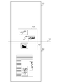
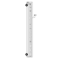
- FIG. 8A is a diagram showing the object 801.
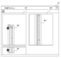
- FIG. 8B is a diagram illustrating a print preview screen in which an object is divided into three pages.
- a vertically long object 801 as shown in FIG. 8A it extends over a plurality of pages of two or more pages as shown in FIG. 8B.
- the objects 802, 803, and 804 obtained by dividing the object 801 can be displayed and edited on each page.
- an object may be arranged across three or more pages, and the object may be divided into three or more pages and laid out.
- a recording medium in which a program code of software that realizes the functions of the above-described embodiments is recorded may be supplied to the system or apparatus.
- the object of the present invention is achieved by the computer (or CPU or MPU) of the system or apparatus reading and executing the program code stored in the recording medium.
- the program code itself read from the storage medium realizes the functions of the above-described embodiment, and the program code itself and the storage medium storing the program code constitute the present invention.
- the present invention is not limited to the implementation of the functions of the above-described embodiments by executing the program code read by the computer.
- OS operating system
- the present invention can also be realized by a plurality of processors such as a CPU and an MPU executing processes in cooperation.
Landscapes
- Engineering & Computer Science (AREA)
- Theoretical Computer Science (AREA)
- General Engineering & Computer Science (AREA)
- General Physics & Mathematics (AREA)
- Physics & Mathematics (AREA)
- Artificial Intelligence (AREA)
- Health & Medical Sciences (AREA)
- Audiology, Speech & Language Pathology (AREA)
- Computational Linguistics (AREA)
- General Health & Medical Sciences (AREA)
- Databases & Information Systems (AREA)
- Data Mining & Analysis (AREA)
- Human Computer Interaction (AREA)
- Multimedia (AREA)
- Signal Processing (AREA)
- Editing Of Facsimile Originals (AREA)
- Processing Or Creating Images (AREA)
- Document Processing Apparatus (AREA)
- User Interface Of Digital Computer (AREA)
Abstract
ユーザによる指示に応じて、少なくとも1つの要素を含むオブジェクトを、前記オブジェクトが配置されるドキュメント上で移動させ、移動したオブジェクトに含まれる要素の、前記ドキュメントにおける位置を示す情報を取得する。 また、オブジェクトが2つのページの境界に移動された場合に、取得された情報に基づき、前記オブジェクトに含まれる、前記2つのページの区切りの位置に対応する少なくとも1つの要素を検出する。 そして、検出された少なくとも1つの要素が、前記2つのページのドキュメントのいずれかに配置されるようにドキュメント上で要素が配置される位置を決定して、ドキュメントに対応する画像を出力する。 これにより、要素を適切にドキュメントに配置して出力することができる。
Description
本発明は、要素が配置されたドキュメントに対応する画像を出力する画像処理装置に関する。
テキストや画像、グラフィック等が混在した画像の印刷レイアウトを編集するシステムが知られている。このようなシステムは、文書編集ソフトやドローソフト、デジタルカメラで撮影した画像でアルバムを作成するためのアルバムソフト等で用いられる。
こうしたシステムでは一般的に、ユーザがマウス等のポインティングデバイスを操作することで、画像内のグラフィックオブジェクトの移動・拡大・縮小を行うことができる。これらのオブジェクトをページに対してレイアウトした場合に、移動や拡大されたオブジェクトがページの境界を越える場合があり、図やグラフィックを作成するドローソフトの一部にも、ページ間をまたいでオブジェクトを編集できるものがある。
例えば見開きページに画像をレイアウトするアルバムソフトの場合、見開きページの折り目に画像が重なる場合がある。そこで特許文献1には、見開きページに予め設定されているレイアウト枠に画像をレイアウトするときに、画像のうち人物等に対応する領域がページの折り目に重ならないように、人物等の画像を折り目からずらして配置する技術が記載されている。
また他にも、表をページ間でまたがせる文書編集アプリケーションが知られている。
特許文献1に記載の技術は、見開きページに予め決められているレイアウト枠に画像をレイアウトしている。よって、ユーザが画像を任意に拡大、移動等の編集をするものではなく、またユーザが編集を行った画像のレイアウトを行うものではない。
即ち、ユーザは任意に画像を移動、拡大させることができない。
一方、ユーザがページ内のオブジェクトの編集を行う場合、ユーザの任意で編集を行った結果、オブジェクトがページの区切りの位置に配置される場合がある。このとき、オブジェクトをページの区切りの位置で分割した場合、分割されたオブジェクトの内容をユーザが認識し難くなる場合がある。
また、文書編集アプリケーションにおいて表をページ間でまたがせる場合、表の行をテキストと同じ行とみなしてページ間で改行を行っている。ここで、文書編集アプリケーションにおけるページ間の改行について図12A、図12Bを用いて説明する。図12Aに示すように、ページ1201のページ後端まで文字が埋まると、ページ1201の次ページであるページ1202の前端の行に改行される。同様に、図12Bに示すように、ページ間が連続して上下に配置されないページ1203、1204においても、ページ1203の後端の行からページ1204の前端への改行1205を行う。上述のように表をページ間でまたがせる場合、図12A、図12Bで示したテキストの改行と同様に、表の行が次ページに送られて表が分割される。
よって、ユーザが表の全体を把握したい場合であっても、表がページ間で分割されてしまうため、表の内容をユーザが認識し難くなる場合がある。
そこで本発明は、要素を適切にドキュメントに配置して出力することができる画像処理装置を提供する。
本発明は、ユーザによる指示に応じて、少なくとも1つの要素を含むオブジェクトを、前記オブジェクトが配置されるドキュメント上で移動させる移動手段と、前記移動手段により前記ドキュメント上で移動させたオブジェクトに含まれる要素の、前記ドキュメントにおける位置を示す情報を取得する取得手段と、前記移動手段により、前記オブジェクトが2つのページの境界に移動された場合に、前記取得手段により取得された情報に基づき、前記オブジェクトに含まれる、前記2つのページの区切りの位置に対応する少なくとも1つの要素を検出する検出手段と、前記検出手段により検出された少なくとも1つの要素が前記2つのページのいずれかに配置されるように、ドキュメント上で要素が配置される位置を決定する決定手段と、前記決定手段により決定された位置に要素が配置されたドキュメントに対応する画像を出力する出力手段と、を有することを特徴とする
本発明によれば、要素を適切にドキュメントに配置して出力することができる。
以下、添付図面を参照して本発明の好適な実施の形態を詳しく説明する。尚、以下の実施の形態は特許請求の範囲に係る本発明を限定するものでなく、また本実施の形態で説明されている特徴の組み合わせの全てが本発明の解決手段に必須のものとは限らない。
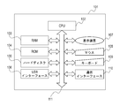
図1は、レイアウト編集装置の構成を示すブロック図である。101は、レイアウト編集装置の一例としてのPC(Personal Computer)である。
CPU102は、プログラムに従ってデータの演算や命令を行い、PC101の各部や接続された装置に対する制御を行う。RAM103は、一時記憶領域として使用されるメモリであり、ROM104は、CPU102により実行される各種のプログラムを保存するメモリである。ハードディスク105はオペレーティングシステム(OS)、ブラウザやその他のアプリケーションソフトのプログラムやデータ等を記録する。つまり、CPU102が、ROM104或いはハードディスク105に格納されたプログラムをRAM103に読出し、RAM103をワークメモリとしてプログラムを実行することで各種の制御が行われる。
CPU102は、プログラムに従ってデータの演算や命令を行い、PC101の各部や接続された装置に対する制御を行う。RAM103は、一時記憶領域として使用されるメモリであり、ROM104は、CPU102により実行される各種のプログラムを保存するメモリである。ハードディスク105はオペレーティングシステム(OS)、ブラウザやその他のアプリケーションソフトのプログラムやデータ等を記録する。つまり、CPU102が、ROM104或いはハードディスク105に格納されたプログラムをRAM103に読出し、RAM103をワークメモリとしてプログラムを実行することで各種の制御が行われる。
USBインターフェース106は、USBケーブルが接続されるインターフェースであり、不図示のプリンタとのデータ通信を行うためのインターフェースである。なおプリンタとの通信はUSBケーブル以外でも、例えばSCSIや無線により行われてもよい。
表示装置107はCRTや液晶ディスプレイとグラフィックコントローラとからなり、PC101の表示制御により種々の表示がされる。例えば通信インターフェース110を経由してWWWサーバーからダウンロードした構造化文書に基づくWebページや、印刷プレビュー画像、またグラフィックユーザインターフェース(GUI)等の表示が行われる。
マウス108やキーボード109はユーザがPC101に対して各種指示を与えるための入力装置である。システムバス111は、CPU102やRAM103、ROM104、ハードディスク105等との間のデータのやり取りを行う。
通信インターフェース110はLANケーブルが接続されるインターフェースであり、不図示のルータ、またインターネットを介して外部のWWWサーバーとのデータ通信が行われる。なおこのデータ通信は、例えば無線に対応したインターフェースにより、無線で行われてもよい。
図2はPC101上のソフトウェアの構成を示すブロック図である。以下にPC101上で動作するプログラムとそのデータ処理構成について図2を用いて説明する。
図2においてブラウザ201はWebページを表示するためのアプリケーションであり、不図示のWWWサーバー上の構造化文書ファイルをPC101上のハードディスク105へダウンロードする。そして、この構造化文書ファイルに基づき表示装置107にWebページを表示させる。構造化文書ファイルはHTMLやXHTML等の構造化言語で記述されており、具体的にはテキストや画像等の構造化文書を構成する要素がタグを用いて記述されている。またこれら要素の表示スタイルを指定するCascading Style Sheet(以下CSSと略す)と呼ばれる別ファイルが構造化文書内に指定されている。ブラウザ201はこれらの構造化文書ファイルを解析し表示装置107へWebページを表示させる。
図2はPC101上のソフトウェアの構成を示すブロック図である。この図2に示された各ブロックはROM104やハードディスク105に保存されているプログラムを機能ごとに分類したものであり、これらのプログラムはCPU102により実行される。図2において構造化文書印刷モジュール202はブラウザ201から呼び出されるプラグインソフトウェアであり、ユーザがブラウザ201に対して印刷もしくは印刷プレビュー指示を行ったときこの構造化文書印刷モジュール202が実行される。
文書切出し部203は、構造化文書の一部を切出す。ブラウザ201により表示されたWebページ上においてユーザがマウス等のポインティングデバイスを使用して印刷領域を決定させると、その領域を切出す。中間ファイル作成部204は、文書切出し部203により切出された印刷領域に対応した、例えばEMF(Enhanced Metafile)などの形式の中間ファイルを、グラフィックオブジェクトとして作成する。そしてこの中間ファイルは、中間ファイル記憶部205に記憶される。なお、この中間ファイルは、Webページにおける要素をテキストや画像をベクターデータとして保持する。従って、この中間ファイルに基づき表示されるオブジェクトに対して拡大等の編集を行った場合に、ビットマップ等の画像データに編集を行った場合に比べて、画質の低下を抑えることができる。
印刷レイアウト部206は、印刷設定に従って中間ファイルのグラフィックオブジェクトを用紙サイズにレイアウトする。この印刷設定は用紙サイズ、解像度、印刷可能領域等の情報を含み、OS209を介してプリンタドライバ210から取得する。
印刷プレビュー部207は印刷レイアウト部206でレイアウトしたグラフィックオブジェクトを印刷プレビューとして表示装置107に表示させる。印刷処理部208は、ユーザにより印刷開始指示をうけた場合に、OS209を介してプリンタドライバ210に対して描画処理を実行する。その際、印刷レイアウト部206によるレイアウトを示す情報に従って配置された中間ファイルのオブジェクトに基づき、描画処理が実行される。
OS209は構造化文書印刷モジュール202がプリンタドライバ210から印刷設定データのやり取りを行うためのAPI(Application Programing Interface)や描画処理を行うためのAPIを提供する。またOS209には印刷のジョブを管理するスプーラーシステム、プリンタコマンドをポートへ出力するポートモニター等の各種制御ソフトウェアが含まれるが詳細については省略する。プリンタドライバ210は印刷処理部208により実行された描画処理にしたがって印刷データを生成する。そして生成した印刷データをプリンタコマンドに変換して、OS209を介してプリンタコマンドをプリンタ211に送信して、プリンタ211に画像を用紙へ印刷させる。
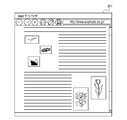
次に文書切出し部203の処理により表示されるGUI画面について説明する。図3A、図3BはGUI画面を示す図である。
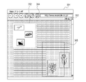
ブラウザ301内にはWebページが表示されている。ユーザがクリップボタンを押下すると図3Bのようにクリップモードに入り、Webページがグレーのウィンドウが重なって表示される。ユーザがその中で自分が印刷したい領域を指定するためにドラッグ操作を行うと、文書切出し部203の処理により選択領域302が切出されて、この選択した領域が、グレーのウィンドウが重ならない通常の表示に変わる。なお、この状態で選択領域302を移動・拡大・縮小することも可能である。
ユーザは、印刷したい領域が確定したら、確定ボタン303を押してクリップモードを終了させる。すると、Webページにおける選択領域302は、中間ファイル作成部204によりEMFファイル化されて中間ファイル記憶部205に記憶される。そして、図3Bに示す印刷プレビューボタン304がユーザにより押下されると、印刷プレビュー部207の処理により印刷プレビュー画面が表示される。
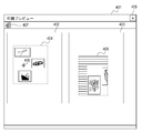
図4A,図4B,図4C、図4Dは、印刷プレビュー画面を示す図である。印刷プレビュー画面401内には、図12Bで示したように、ページ402、403が連続しないで横並びで表示されている。尚、オブジェクト404はWebページの選択領域302、オブジェクト405はWebページの選択領域305に基づき作成されたEMFファイル形式の中間ファイルである。このように同じWebページから複数の領域を選択しても、複数のWebページから複数の領域を選択しても構わない。
ここでは、印刷レイアウト部206の処理により、このようなオブジェクトをページ間で分割して表示することができる。ここでは、マウスポインタ406によってオブジェクト404を指定して、図4の下方に移動する場合を例にとって説明する。
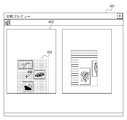
図4Bは移動中のオブジェクト404を示す図である。ここでは、オブジェクトが移動中であることを識別できるように例えばグレーの網掛けの状態で移動中のオブジェクト404を表示する。このグレーの網掛けの状態はマウスボタンをリリースすることで編集作業が確定した段階で通常の状態に戻る。
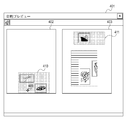
そして、マウスポインタ406を更に下方にドラッグして、オブジェクト404がページ402の後端からはみ出した場合、図4Cに示すように第1ページ用オブジェクト410、第2ページ用オブジェクト411に分割される。更に、マウスポインタ406を下方にドラッグし、マウスポインタ406がページ402の下端を超えた場合、図4Dのように新しいページ412を作成する。そして、オブジェクト404は第1ページ用オブジェクト413、第2ページ用オブジェクト414に分割され、それぞれページ403、412に表示される。
なお、図4Cに示すマウスポインタ409がページ402の下端を超えた場合に、オブジェクトを配置するページを図4Cの状態から変更させなくてもよい。また、マウスポインタ409がページ402の下端を超えた場合に、マウスポインタをページ403の上端に移動させても良い。即ち、ユーザはマウスポインタ409をページ402の下方向に移動させる操作に連続して、マウスポインタ409をページ403の下方向に移動させることができる。よって、マウスポインタ409がページ402の下端を超えても、ページ403の上端に配置されているオブジェクトを指定できるため、オブジェクトの移動や拡大のための操作を、ページをまたいで連続して行うことができる。
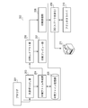
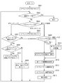
図5は印刷レイアウト部206の構成を示すブロック図である。また図6は、オブジェクト編集処理の処理手順を示す図であり、印刷レイアウト部206が、図4Aから図4Dに示したオブジェクトを移動させる処理を、図6のフローを用いて説明する。
まず、印刷プレビューボタン304を押下で印刷プレビュー画面401が表示されると編集モードに入り、編集指示部501はユーザからの編集指示を受け付けるため、イベントフラグを初期化して(S601)、ユーザからの指示待機状態に入る。そして、印刷ボタン407か終了ボタン408の押下されたか確認することにより、編集モードを終了するか判定する(S602)。印刷ボタン407か終了ボタン408が押下されたことが確認されると、編集モードを終了する。
印刷ボタン407か終了ボタン408の押下ではないユーザからのマウスイベントを検出すると、そのマウスイベントの種類を判断する(S603)。ここで検出されるマウスイベントは、ボタンリリース・ボタンクリック・ポインタ移動のいずれかである。まず、ボタンリリースイベントの場合は、オブジェクトの編集終了を意味するのでイベントフラグを初期化してユーザからの指示待機状態に入る(S604)。
一方、ボタンクリックイベントの場合は、オブジェクト取得部502がそのクリックされたページにおける座標を取得し、その座標でオブジェクトが検出されるか否かを判別する(S605)。オブジェクトが検出されなかった場合はそのまま指示待機状態に戻る。一方、オブジェクトが検出された場合は、オブジェクト取得部502が該当のオブジェクトを中間ファイル記憶部205から取得し、オブジェクトのページにおける座標・マウスポインタのページにおける座標を記憶すると共にオブジェクトのどこをクリックしたかを検出する(S606)。オブジェクトの内部をクリックされた場合はイベントフラグに移動フラグをセットし(S607)、オブジェクトの外周をクリックされた場合はイベントフラグに拡大・縮小フラグをセットして(S608)、指示待機状態に戻る。
また一方、S603でポインタ移動イベントが検出された場合、イベントフラグにいずれのフラグが設定されているかを調べる(S609)。イベントフラグが設定されていない場合は、単なるマウスポインタ406の移動であるので指示待機状態に戻る。移動フラグが設定されていた場合は、現在のマウスポインタの座標とクリック時のマウスポインタの座標からマウスの移動量を計算し、クリック時のオブジェクトの座標に加算する事で求めた座標にオブジェクトを移動する(S610)。拡大・縮小フラグが設定されていた場合は、移動時と同様にマウスの移動量を計算し、オブジェクトの拡大率・縮小率を計算し、オブジェクトの拡大・縮小を行う(S611)。このようにオブジェクト取得部502の処理によりオブジェクトの移動または拡大・縮小が行われると、改ページ座標検出部503にオブジェクトのページにおける座標やサイズが渡されて、改ページ座標検出処理に進む。尚、オブジェクト404の拡大・縮小方法についての詳細な説明は省略する。オブジェクトの移動・拡大・縮小が終わったら指示待機状態に戻る。
改ページ座標検出部503は、オブジェクト取得部502から送られたオブジェクト404のサイズ・座標からオブジェクト404が改ページ座標に重なっているかを検出する(S612)。
図7は、改ページ座標検出部503におけるページレイアウトを示す図であり、このとき改ページ座標検出部503内では図7のようにページ間が連続したレイアウトで原稿を扱う。つまり、ページ402、403がページ701、702にマッピングされる。ここでオブジェクト404が移動してページ701と702の境界である改ページ境界703に重なった場合、オブジェクト404のページにおける座標・サイズとページ境界703のページにおける座標からオブジェクトの分割座標を計算する。この分割座標とは、オブジェクト404において分割される座標を示し、この分割座標をオブジェクト分割部504へ送る。
オブジェクト分割部504は取得したオブジェクト分割座標に従って、オブジェクト404を第1ページ用オブジェクト410、第2ページ用オブジェクト411に分割する(S613)。分割したオブジェクトは、それぞれのサイズ・座標と共にオブジェクト配置部505に送られる。
オブジェクト配置部505は、図4Cに示すようにページ402に第1ページ用オブジェクト410、第2ページ用オブジェクト411を配置し(S614)、印刷プレビュー部207にページ701、702を示す画像を送る。すると、印刷プレビュー部207は、印刷プレビュー画面401にGUI表示を行う(S615)。
また図4Dは、図4Cに示すマウスポインタ409が、図4Cの状態から更に下に移動してページ402の下端を超えた場合のGUI表示を示す。このとき、改ページ座標検出部503・オブジェクト分割部504により図4Cと同様にオブジェクトを分割するが、分割されたオブジェクトが配置されるページが異なる。ここでオブジェクト配置部505は、第1ページ用オブジェクトとなるオブジェクト413をページ402ではなくページ403へ配置する。そして、第2ページ用オブジェクトであるオブジェクト414をページ403ではなく、その後ろに追加したページ412へ配置する。このように、それぞれ1ページずつ後のページに配置することにより、図4Dで示したレイアウトを表示する。
次に、上述した印刷プレビュー画面とは異なる別の例について説明する。尚、上記で説明した構成と同一の構成についてはその説明を省略する。
図9Aは印刷プレビュー部207のGUI表示を示す図である。上述した印刷プレビュー画面401に対して、印刷プレビュー画面901は、ページ402、403に対して、印刷可能領域902、903が追加されている。この印刷可能領域とは、プリンタで印刷される用紙における印刷が可能な領域を示す。つまり、プリンタで印刷する際に用紙の搬送誤差等の要因で用紙全体には印刷できず、用紙内で印刷可能とする領域が設定されている。これは使用するプリンタ毎に異なり、プリンタドライバ210から取得している。
尚、この印刷可能領域902、903を示す点線は実際には印刷されないものであり、印刷プレビュー画面901においても、その範囲を明らかにするために表示している。上述した例と同様にマウスポインタ406を用いてオブジェクト404を下方に移動する場合を例に説明する。
まず編集指示部501では上述した例と同様にオブジェクトの編集を指示する。またオブジェクト取得部502では、上述した例と同様にオブジェクトのページにおける座標やサイズを取得する処理を行う。ただし、マウスポインタ406が印刷可能領域902の後端からページ402の後端までの間にある場合は、マウスポインタ406の座標を印刷可能領域902の先後端にマッピングして扱う。尚、ここではマウスポインタ406が印刷可能領域902の下端を超える場合を例に説明するが、上端・左端・右端でも同様な動作をする。
改ページ座標検出部503では、上述した例と同様に、ページを図7で示したページ701、702のように扱う。ただし、上述した例と異なり、この内部で扱うページ701、702のサイズはページ402、403のサイズではなく、印刷可能領域902、903のサイズとなる。
そして、オブジェクト分割部504でオブジェクトを分割し、オブジェクト配置部505で分割したオブジェクトを配置する。その配置は図9Bのように、印刷可能領域902内に第1ページ用オブジェクト904、印刷可能領域903内に第2ページ用オブジェクト905が配置される。
なお、ここではページサイズに対して印刷可能領域を設定した場合で説明したが、ユーザが任意に設定した余白をページサイズに対して設定して、設定された余白を示すように印刷プレビューを表示しても構わない。
このように印刷を行うプリンタの印刷可能領域内にオブジェクトをレイアウトすることで、実際の印刷結果に即した印刷プレビュー上でオブジェクトを自由に編集することを可能とする。
次に、オブジェクトの区切り位置の決定について説明する。尚、上述した構成と同一の構成については、その説明を省略する。
図10A、図10B、図10Cは、オブジェクトとページ区切りとの関係を示す図である。図10Aにおけるオブジェクトは、ブラウザ201で表示したWebページから文書切出し部203で領域が切出され、中間ファイル作成部204でEMFファイル形式の中間ファイルとして抽出されている。なお、オブジェクト1001内には要素1002、1003、1004、1005、1006(要素1002、1003、1004は画像要素、要素1005、1006はテキスト要素)が存在する。そして、オブジェクト取得部502は、オブジェクト1001を取得し、改ページ座標検出部503はオブジェクト1001内に第1のオブジェクト分割座標1007を設定する。
オブジェクト分割部504は、まずオブジェクト1001内の第1のオブジェクト分割座標1007に存在する要素を検出する。検出された要素が画像要素であれば(図10Aでは要素1003)、その要素の先頭位置、または先頭位置より所定の範囲内に要素が無い分割座標となる座標があるか確認して、その座標を第2のオブジェクト分割座標1008とする。
さらに、第1のオブジェクト分割座標1007にテキスト要素が存在するか確認する。そして存在すれば(図10Aでは要素1005内の4行目であるテキスト行1010)、文字列のサイズに従い、そのテキスト行1010と上位(先頭に近い1つ前)のテキスト行との間を第3のオブジェクト分割座標1009とする。
図10B、図10Cはそれぞれ、オブジェクト分割部504によってオブジェクト1001が分割された後の第1ページ用オブジェクト1011、第2ページ用オブジェクト1013を示す図である。オブジェクト1001の分割時に、第1のオブジェクト分割座標1007に存在した画像要素1003は全て第2ページ用オブジェクト1013に配置され、第1ページ用オブジェクト1011には表示されない。また、第1のオブジェクト分割座標1007に存在した、テキスト要素1005内のテキスト行1010以降のテキスト行は、第2ページ用オブジェクト1013に要素1014として配置される。そして、テキスト要素1005内のテキスト行1010より前のテキスト行は第1ページ用オブジェクト1011に要素1012として配置される。尚、画像要素1003を第1ページ用オブジェクト1011、第2ページ用オブジェクト1013のどちらに配置するかは、オブジェクト分割座標1009と画像要素1003との相対位置に応じて決定してもよいし、所定の側に配置するようにしてもよい。
図11は、印刷プレビュー画面を示す図である。図11に示されるように、オブジェクト1001は第1ページ用オブジェクト1011と第2ページ用オブジェクト1013に分割されて配置される。このように、まずオブジェクト1001を分割すべきであった第1のオブジェクト分割座標1007に対して、分割する座標をテキスト要素の文字と重ならない位置にずらす。そして、その位置では画像要素と重なってしまう場合、その画像要素をいずれかのページのオブジェクトに含ませる。したがって、オブジェクト内の要素が改ページ座標に重なる場合、画像要素は全体を、またテキスト要素の場合は行間で分けられた一部を、それぞれ次ページに送ることができる。よって、ユーザにとって区切りのいい位置で改ページを行うことができる。
以上のように、本実施例によれば、オブジェクトを分割して、ページに適切にレイアウトすることができる。また、複数のページが連続して表示されないページレイアウトであっても、ページ間をまたいだオブジェクトの編集をすることができる。さらに、オブジェクトをページの区切りの位置で分割してレイアウトするので、各ページのレイアウトは、分割されたオブジェクトであったとしても、通常のオブジェクトと同様の処理でレイアウトすることができる。その場合、ユーザの指示によりページ区切りの位置に対応するオブジェクトの変更された場合に、オブジェクトの分割座標を更新して、更新された分割座標に応じてオブジェクトを分割することによって実現できる。
なお、以上の実施例では、表示画面においてページの上下に対応するページ区切りについて説明した。しかし、表示画面におけるページの左右に対応するページ区切りに基づき、オブジェクトを分割してもよい。即ち、ユーザはオブジェクトを表示画面の左右方向に移動や拡大させることにより、表示画面上で左右に隣接する2つのページでオブジェクトを分割することができる。
また上記の説明では、オブジェクト404が2ページにまたがる例で説明したが、これに限らず、3ページ以上にまたがってもよい。図8Aは、オブジェクト801を示す図である。図8Bは、オブジェクトを3ページに分割した印刷プレビュー画面を示す図である。図8Aのように縦長のオブジェクト801の場合は、図8Bに示すように2ページ以上の複数ページにまたがる。この場合、オブジェクト801が分割されたオブジェクト802、803、804を各ページに表示して編集することも可能である。
さらに、オブジェクトを3つ以上のページにまたがせて配置して、オブジェクトを3つ以上のページに分割してレイアウトしてもよい。
なお、本発明は、前述した実施例の機能を実現するソフトウェアのプログラムコードを記録した記録媒体をシステムあるいは装置に供給するものであってもよい。その場合、そのシステムあるいは装置のコンピュータ(またはCPUまたはMPU)が記録媒体に格納されたプログラムコードを読み出し実行することによって、本発明の目的が達成される。この場合、記憶媒体から読み出されたプログラムコード自体が前述した実施形態の機能を実現することとなり、そのプログラムコード自体、またそれを記憶した記憶媒体は本発明を構成することになる。
また本発明は、コンピュータが読み出したプログラムコードを実行することにより、前述した実施例の機能が実現されるだけに限らない。例えば、そのプログラムコードの指示に基づき、コンピュータ上で稼動しているOperating System(OS)などが実際の処理の一部または全部を行い、その処理によって前述した実施例の機能が実現される場合であってもよい。さらに、本発明は、CPUやMPU等の複数のプロセッサが連携して処理を実行することによっても実現される。
101 PC
102 CPU
103 RAM
104 ROM
105 ハードディスク
106 USBインターフェース
107 表示装置
108 マウス
109 キーボード
110 通信インターフェース
111 システムバス
102 CPU
103 RAM
104 ROM
105 ハードディスク
106 USBインターフェース
107 表示装置
108 マウス
109 キーボード
110 通信インターフェース
111 システムバス
Claims (11)
- ユーザによる指示に応じて、少なくとも1つの要素を含むオブジェクトを、前記オブジェクトが配置されるドキュメント上で移動させる移動手段と、
前記移動手段により前記ドキュメント上で移動させたオブジェクトに含まれる要素の、前記ドキュメントにおける位置を示す情報を取得する取得手段と、
前記移動手段により、前記オブジェクトが2つのページの境界に移動された場合に、前記取得手段により取得された情報に基づき、前記オブジェクトに含まれる、前記2つのページの区切りの位置に対応する少なくとも1つの要素を検出する検出手段と、
前記検出手段により検出された少なくとも1つの要素が前記2つのページのいずれかに配置されるように、ドキュメント上で要素が配置される位置を決定する決定手段と、
前記決定手段により決定された位置に要素が配置されたドキュメントに対応する画像を出力する出力手段と、
を有することを特徴とする画像処理装置。
- 前記オブジェクトは、構造化文書により定義された要素を含むことを特徴とする請求項1に記載の画像処理装置。
- 前記オブジェクトは、構造化文書に基づきWebブラウザにより表示されたWebページのうちユーザにより指定された領域に対応したオブジェクトであることを特徴とする請求項2に記載の画像処理装置。
- 構造化文書により定義された要素をベクタ形式とした中間ファイルを生成する生成手段を有し、
前記決定手段は、前記生成手段により生成された中間ファイルに含まれる要素の、ドキュメントにおける位置を決定することを特徴とする請求項2に記載の画像処理装置。
- 前記出力手段は、前記決定手段により決定された位置に要素が配置されたドキュメントに対応する画像を印刷装置に出力して印刷させることを特徴とする請求項1に記載の画像処理装置。
- 前記出力手段は、前記決定手段により決定された位置に要素が配置されたドキュメントに対応する画像を表示装置に出力して表示させることを特徴とする請求項1に記載の画像処理装置。
- 前記決定手段は、前記検出手段により検出された要素の内容に応じて、前記要素が分割可能な内容である場合には、前記要素が2つのページのドキュメントに分割されて配置されるように、ドキュメント上で要素が配置される位置を決定することを特徴とする請求項1に記載の画像処理装置。
- 前記取得手段は、前記移動手段により移動したオブジェクトの前記ドキュメントにおける位置を示す第1の情報と、前記オブジェクトにおける前記2つのページの区切りの位置に対応する位置を示す第2の情報とを取得し、前記検出手段は、前記取得手段により取得された前記第1の情報と前記第2の情報とに基づき、前記2つのページの区切りの位置に対応する要素を検出することを特徴とする請求項1に記載の画像処理装置。
- 前記移動手段は、ユーザによる指示に応じて、ページに配置されているオブジェクトを前記ドキュメント上で移動または拡大させることを特徴とする請求項1に記載の画像処理装置。
- ユーザによる指示に応じて、少なくとも1つの要素を含むオブジェクトを、前記オブジェクトが配置されるドキュメント上で移動させる移動工程と、
前記移動工程において前記ドキュメント上で移動させたオブジェクトに含まれる要素の、前記ドキュメントにおける位置を示す情報を取得する取得工程と、
前記移動工程により、前記オブジェクトが2つのページの境界に移動された場合に、前記取得工程において取得された情報に基づき、前記オブジェクトに含まれる、前記2つのページの区切りの位置に対応する少なくとも1つの要素を検出する検出工程と、
前記検出工程において検出された少なくとも1つの要素が前記2つのページのドキュメントのいずれかに配置されるように、ドキュメント上で要素が配置される位置を決定する決定工程と、
前記決定工程において決定された位置に要素が配置されたドキュメントに対応する画像を出力する出力工程と、
を有することを特徴とする画像処理方法。
- 請求項10に記載の画像処理方法をコンピュータに実行させるためのプログラムを記憶した記憶媒体。
Priority Applications (2)
| Application Number | Priority Date | Filing Date | Title |
|---|---|---|---|
| US12/903,170 US8819543B2 (en) | 2009-06-09 | 2010-10-12 | Image processing apparatus, image processing method, and storage medium |
| US14/460,213 US9659107B2 (en) | 2009-06-09 | 2014-08-14 | Image processing apparatus, image processing method, and storage medium |
Applications Claiming Priority (2)
| Application Number | Priority Date | Filing Date | Title |
|---|---|---|---|
| JP2009-138400 | 2009-06-09 | ||
| JP2009138400A JP5371560B2 (ja) | 2009-06-09 | 2009-06-09 | レイアウト編集装置、レイアウト編集方法及びプログラム |
Related Child Applications (1)
| Application Number | Title | Priority Date | Filing Date |
|---|---|---|---|
| US12/903,170 Continuation US8819543B2 (en) | 2009-06-09 | 2010-10-12 | Image processing apparatus, image processing method, and storage medium |
Publications (1)
| Publication Number | Publication Date |
|---|---|
| WO2010143621A1 true WO2010143621A1 (ja) | 2010-12-16 |
Family
ID=43308876
Family Applications (1)
| Application Number | Title | Priority Date | Filing Date |
|---|---|---|---|
| PCT/JP2010/059673 Ceased WO2010143621A1 (ja) | 2009-06-09 | 2010-06-08 | 画像処理装置、画像処理方法及び記憶媒体 |
Country Status (3)
| Country | Link |
|---|---|
| US (2) | US8819543B2 (ja) |
| JP (1) | JP5371560B2 (ja) |
| WO (1) | WO2010143621A1 (ja) |
Families Citing this family (14)
| Publication number | Priority date | Publication date | Assignee | Title |
|---|---|---|---|---|
| JP5371560B2 (ja) * | 2009-06-09 | 2013-12-18 | キヤノン株式会社 | レイアウト編集装置、レイアウト編集方法及びプログラム |
| JP5655347B2 (ja) * | 2010-03-31 | 2015-01-21 | ブラザー工業株式会社 | 画像処理制御プログラム、及び画像形成装置 |
| JP5801545B2 (ja) * | 2010-10-15 | 2015-10-28 | キヤノン株式会社 | 情報処理装置、その情報処理方法及びプログラム |
| RU2458396C1 (ru) * | 2011-07-19 | 2012-08-10 | Корпорация "САМСУНГ ЭЛЕКТРОНИКС Ко., Лтд." | Способ редактирования статических цифровых комбинированных изображений, включающих в себя изображения нескольких объектов |
| JP5539280B2 (ja) * | 2011-09-07 | 2014-07-02 | キヤノン株式会社 | データ処理装置、データ処理方法およびプログラム |
| JP5810049B2 (ja) * | 2011-12-08 | 2015-11-11 | 京セラドキュメントソリューションズ株式会社 | 画像形成装置及び画像形成システム |
| KR101596084B1 (ko) * | 2011-12-20 | 2016-02-19 | 캐논 가부시끼가이샤 | 화상 처리 장치, 화상 처리 장치 제어 방법 및 저장 매체 |
| JP5582151B2 (ja) | 2012-01-12 | 2014-09-03 | コニカミノルタ株式会社 | 画像形成装置及び同装置における文書データのプレビュー表示方法 |
| JP5949219B2 (ja) * | 2012-06-29 | 2016-07-06 | ブラザー工業株式会社 | 画像処理システム、画像処理装置、画像処理方法、および画像処理プログラム |
| CN106649348B (zh) * | 2015-10-30 | 2020-03-31 | 北京国双科技有限公司 | 页面表格布局方法及装置 |
| JP6742850B2 (ja) | 2016-07-29 | 2020-08-19 | キヤノン株式会社 | レイアウト編集装置、レイアウト編集方法、およびプログラム |
| JP7121363B2 (ja) * | 2019-03-28 | 2022-08-18 | ミールソリューションズ株式会社 | 大規模電子文書の版管理方法とその版管理システム |
| JP7318387B2 (ja) * | 2019-07-24 | 2023-08-01 | 富士フイルムビジネスイノベーション株式会社 | 画像処理装置、情報処理プログラム |
| KR102739722B1 (ko) * | 2019-08-22 | 2024-12-09 | 삼성전자주식회사 | 디스플레이장치와 그의 제어방법, 및 기록매체 |
Citations (6)
| Publication number | Priority date | Publication date | Assignee | Title |
|---|---|---|---|---|
| JPS60164874A (ja) * | 1984-02-08 | 1985-08-27 | Fujitsu Ltd | 図版組み込み処理方法 |
| JP2000316131A (ja) * | 1999-04-30 | 2000-11-14 | Matsushita Electric Ind Co Ltd | 画像撮像装置 |
| JP2006252122A (ja) * | 2005-03-10 | 2006-09-21 | Canon Inc | 情報処理装置及び方法、プログラム |
| JP2007012030A (ja) * | 2005-05-30 | 2007-01-18 | Fujifilm Holdings Corp | アルバム作成装置、アルバム作成方法、およびアルバム作成プログラム |
| JP2007017945A (ja) * | 2005-06-10 | 2007-01-25 | Canon Inc | 情報処理装置及びその方法 |
| JP2008269108A (ja) * | 2007-04-17 | 2008-11-06 | Canon Inc | 情報処理装置及びプログラム |
Family Cites Families (27)
| Publication number | Priority date | Publication date | Assignee | Title |
|---|---|---|---|---|
| JPS62119680A (ja) * | 1985-11-20 | 1987-05-30 | Fujitsu Ltd | 図形移動制御方式 |
| JPH08161517A (ja) * | 1994-12-06 | 1996-06-21 | Canon Inc | 文書処理装置 |
| US5956737A (en) * | 1996-09-09 | 1999-09-21 | Design Intelligence, Inc. | Design engine for fitting content to a medium |
| JPH1170712A (ja) * | 1997-08-28 | 1999-03-16 | Fujitsu Ltd | 改ページ指示方法,ページ管理方法,プリンタシステム及びプリンタ装置 |
| US7356760B2 (en) * | 2001-02-15 | 2008-04-08 | Nbor Corporation | System and method for editing an electronic document of text and graphic objects |
| JP3814585B2 (ja) * | 2002-03-20 | 2006-08-30 | キヤノン株式会社 | 画像処理装置、画像処理方法、プログラム及び記憶媒体 |
| US7246306B2 (en) * | 2002-06-21 | 2007-07-17 | Microsoft Corporation | Web information presentation structure for web page authoring |
| US7185278B1 (en) * | 2002-06-28 | 2007-02-27 | Microsoft Corporation | Separating and moving document objects using the movement of a wiper bar |
| US7188309B2 (en) * | 2002-06-28 | 2007-03-06 | Microsoft Corporation | Resolving document object collisions |
| JP2004175095A (ja) * | 2002-10-04 | 2004-06-24 | Fuji Xerox Co Ltd | 画像形成装置及び方法 |
| US7412646B2 (en) * | 2003-10-23 | 2008-08-12 | Microsoft Corporation | Systems and methods for pagination and co-pagination |
| JP2005158034A (ja) * | 2003-10-31 | 2005-06-16 | Canon Inc | 印刷方法、印刷制御装置、印刷装置及びそれらの制御方法 |
| US7791755B2 (en) * | 2003-11-05 | 2010-09-07 | Canon Kabushiki Kaisha | Document creation method and document creation apparatus for reflecting a document structure of a paper document in an electronic document |
| JP4510535B2 (ja) * | 2004-06-24 | 2010-07-28 | キヤノン株式会社 | 画像処理装置及びその制御方法、プログラム |
| JP2004288220A (ja) * | 2004-07-09 | 2004-10-14 | Sharp Corp | 文書作成装置 |
| JP4095592B2 (ja) * | 2004-08-06 | 2008-06-04 | キヤノン株式会社 | 情報処理装置、情報処理方法ならびにプログラム |
| JP4759378B2 (ja) * | 2004-12-17 | 2011-08-31 | キヤノン株式会社 | 情報処理装置、情報処理方法、制御プログラム |
| TWI274274B (en) * | 2004-12-30 | 2007-02-21 | Teco Image Sys Co Ltd | Method for dividing print document |
| JP4566772B2 (ja) * | 2005-02-14 | 2010-10-20 | キヤノン株式会社 | 画像処理装置、画像処理方法、及びプログラム |
| US20060218492A1 (en) * | 2005-03-22 | 2006-09-28 | Andrade Jose O | Copy and paste with citation attributes |
| EP1886484B1 (en) * | 2005-05-30 | 2020-01-01 | FUJIFILM Corporation | Album creating apparatus, album creating method and program |
| US9324168B2 (en) * | 2008-01-31 | 2016-04-26 | Microsoft Technology Licensing, Llc | Constraint-based correction of shape positions in a diagram |
| US7982749B2 (en) * | 2008-01-31 | 2011-07-19 | Microsoft Corporation | Server-based rasterization of vector graphics |
| US8489986B2 (en) * | 2008-01-31 | 2013-07-16 | Microsoft Corporation | Correcting positions of shapes in a diagram |
| US8127221B2 (en) * | 2008-02-29 | 2012-02-28 | Microsoft Corporation | Optimal sizes of objects in a document |
| JP5371560B2 (ja) * | 2009-06-09 | 2013-12-18 | キヤノン株式会社 | レイアウト編集装置、レイアウト編集方法及びプログラム |
| CA2668807A1 (en) * | 2009-06-12 | 2010-12-12 | Ibm Canada Limited - Ibm Canada Limitee | Resolving inter-page nodes and connectors in process diagrams |
-
2009
- 2009-06-09 JP JP2009138400A patent/JP5371560B2/ja not_active Expired - Fee Related
-
2010
- 2010-06-08 WO PCT/JP2010/059673 patent/WO2010143621A1/ja not_active Ceased
- 2010-10-12 US US12/903,170 patent/US8819543B2/en active Active
-
2014
- 2014-08-14 US US14/460,213 patent/US9659107B2/en not_active Expired - Fee Related
Patent Citations (6)
| Publication number | Priority date | Publication date | Assignee | Title |
|---|---|---|---|---|
| JPS60164874A (ja) * | 1984-02-08 | 1985-08-27 | Fujitsu Ltd | 図版組み込み処理方法 |
| JP2000316131A (ja) * | 1999-04-30 | 2000-11-14 | Matsushita Electric Ind Co Ltd | 画像撮像装置 |
| JP2006252122A (ja) * | 2005-03-10 | 2006-09-21 | Canon Inc | 情報処理装置及び方法、プログラム |
| JP2007012030A (ja) * | 2005-05-30 | 2007-01-18 | Fujifilm Holdings Corp | アルバム作成装置、アルバム作成方法、およびアルバム作成プログラム |
| JP2007017945A (ja) * | 2005-06-10 | 2007-01-25 | Canon Inc | 情報処理装置及びその方法 |
| JP2008269108A (ja) * | 2007-04-17 | 2008-11-06 | Canon Inc | 情報処理装置及びプログラム |
Also Published As
| Publication number | Publication date |
|---|---|
| US20110029859A1 (en) | 2011-02-03 |
| US9659107B2 (en) | 2017-05-23 |
| US20140359427A1 (en) | 2014-12-04 |
| JP5371560B2 (ja) | 2013-12-18 |
| JP2010286904A (ja) | 2010-12-24 |
| US8819543B2 (en) | 2014-08-26 |
Similar Documents
| Publication | Publication Date | Title |
|---|---|---|
| JP5371560B2 (ja) | レイアウト編集装置、レイアウト編集方法及びプログラム | |
| JP5539280B2 (ja) | データ処理装置、データ処理方法およびプログラム | |
| JP5629435B2 (ja) | 情報処理装置、情報処理方法、およびプログラム | |
| JP5455456B2 (ja) | 情報処理装置、情報処理方法、およびプログラム | |
| US8570569B2 (en) | Control device of image formation system and recording medium storing image formation control program | |
| US20090265626A1 (en) | Apparatus and method of controlling display | |
| JP5483934B2 (ja) | 情報処理装置、情報処理方法、およびプログラム | |
| US9389811B2 (en) | Image processing apparatus, image processing method, and recording medium | |
| US20130176597A1 (en) | Information processing apparatus, information processing method, and storage medium storing a program thereof | |
| KR101508075B1 (ko) | 정보 처리 장치, 웹브라우저 제어 방법 및 그 프로그램을 저장한 저장 매체 | |
| JP5947508B2 (ja) | 情報処理装置、情報処理方法およびプログラム | |
| JP5646019B2 (ja) | 画像処理装置、画像処理方法及びプログラム | |
| JP2004213305A (ja) | 印刷制御システムおよび情報処理装置および印刷制御方法およびプログラム | |
| JP5766257B2 (ja) | 情報処理装置、情報処理方法、およびプログラム | |
| JP2021063863A (ja) | 情報処理装置、プログラム及び情報処理方法 | |
| JP2012014282A (ja) | レイアウト編集方法、レイアウト編集装置、およびプログラム |
Legal Events
| Date | Code | Title | Description |
|---|---|---|---|
| 121 | Ep: the epo has been informed by wipo that ep was designated in this application |
Ref document number: 10786152 Country of ref document: EP Kind code of ref document: A1 |
|
| NENP | Non-entry into the national phase |
Ref country code: DE |
|
| 122 | Ep: pct application non-entry in european phase |
Ref document number: 10786152 Country of ref document: EP Kind code of ref document: A1 |